

Page 1

USER MANUAL
04/08/16 CHANNELS
DIGITAL VIDEO RECORDER
INSTRUCTION MANUAL
To obtain the best performance and ensure device function correctly, please read this instruction
manual carefully and completely.
Page 2
2
INSTRUCTION MANUAL
To obtain the best performance and ensure device function correctly, please read this instruction manual carefully and
completely.
FCC Compliance
USER-INSTALLER CAUTION: YOUR AUTHORITY TO OPERATE THIS FCC VERIFIED EQUIPMENT
COULD BE VOIDED IF YOU MAKE CHANGES OR MODIFICATIONS NOT EXPRESSLY APPROVED BY THE
PARTY RESPONSIBLE FOR COMPLIANCE TO PART 15 OF THE FCC RULES.
NOTE: THIS EQUIPMENT HAS BEEN TESTED AND FOUND TO COMPLY WITH THE LIMITS FOR A
CLASS A DIGITAL DEVICE, PURSUANT TO PART 15 OF THE FCC RULES. THESE LIMITS ARE
DESIGNED TO PROVIDE REASONABLE PROTECTION AGAINST HARMFUL INTERFERENCE WHEN THE
EQUIPMENT IS OPERATED IN A COMMERCIAL ENVIRONMENT. THIS EQUIPMENT GENERATES, USES,
AND CAN RADIATE RADIO FREQUENCY ENERGY AND IF NOT INSTALLED AND USED IN
ACCORDANCE WITH THE INSTRUCTION MANUAL, MAY CAUSE HARMFUL INTERFERENCE TO RADIO
COMMUNICATIONS.
OPERATION OF THIS EQUIPMENT IN A RESIDENTIAL AREA IS LIKELY TO CAUSE HARMFUL
INTERFERENCE IN WHICH CASE THE USER WILL BE REQUIRED TO CORRECT THE INTERFERENCE AT
HIS OWN EXPENSE.
THIS CLASS A DIGITAL APPARATUS MEETS ALL REQUIREMENTS OF THE CANADIAN
INTERFERENCE-CAUSING EQUIPMENT REGULATIONS.
WARNINGS, CAUTIONS & COPYRIGHT
WARINGS
TO REDUCE THE RISK OF FIRE OR ELECTRIC SHOCK, DO NOT EXPOSE THIS PRODUCT TO RAIN OR
MISTURE.
DO NOT INSERT ANY METALLIC OBJECT THROUGH VENTILATION GRILLS.
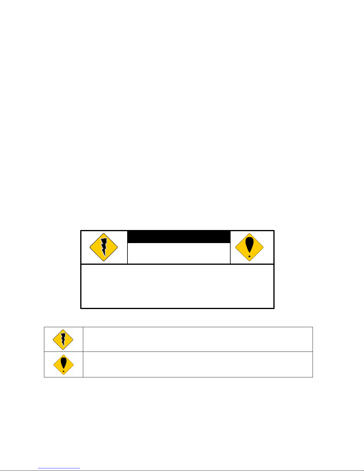
CAUTION
Explanation of Graphical Symbols
The lightning flash with arrowhead symbol, within an equilateral triangle, is intended to alert the
user to the presence of insinuated "dangerous voltage" within the products enclosure that may be of
sufficient magnitude to constitute a risk of electric shock to persons.
The exclamation point within an equilateral rhombus is intended to alert the user to the presence of
important operating and maintenance (servicing) instruction in the literature accompanying the
product.
USERS OF THE SYSTEM ARE RESPONSIBLE FOR CHECKING AND COMPLYING WITH ALL FEDERAL,
STATE, AND LOCAL LAWS AND STATUTES COIPCERNING THE MONITORING AND RECORDING OF
VIDEO AND AUDIO SIGNALS. ULTRAK SHALL NOT BE HELD RESPONSIBLE FOR THE USE OF THIS
SYSTEM IN VIOLATION OF CURRENT LAWS AND STATUTES.
COPYRIGHT
THE TRADEMARKS MENTIONED IN THE MANUAL ARE LEGALLY REGISTERED TO THEIR RESPECTIVE
COMPANIES.
CAUTION: TO REDUCE THE RISK OF ELECTRIC SHOCK.
DO NOT REMOVE COVER (OR BACK).
NO USER-SERVICEABLE PARTS INSIDE.
REFER SERVICING TO QUALIFIED SERVICE PERSONNEL.
RISK OF ELECTRIC SHOCK
DO NOT OPEN
CAUTION
Page 3

3
TABLE OF CONTENTS
1 INTRODUCTION......................................................................................................................5
1.1 FEATURE.......................................................................................................................5
1.2 SPECIFICATION..........................................................................................................5
2 HARDWARE OVERVIEW......................................................................................................8
2.1 FRONT PANEL.............................................................................................................8
2.2 BACK PANEL..............................................................................................................10
2.3 ADVANCED AUTO SWITCH, ZOOM, PTZ, COPY KEY CONTROL & USB
INFORMATION......................................................................................................................12
2.4 EXTERAL ALARM.....................................................................................................12
2.5 IR REMOTE CONTROL...........................................................................................14
3 SYSTEM SETUP .....................................................................................................................15
3.1 MENU SETUP INTERFACE(GUI)...........................................................................15
3.2 LIVE VIEWING AND POP-UP MENU....................................................................17
3.3 CAMERA SETUP........................................................................................................19
3.4 MOTION SETUP.........................................................................................................21
3.5 RECORD SETUP ........................................................................................................23
3.6 ALARM SETUP...........................................................................................................27
3.7 NETWORK SETUP ....................................................................................................27
3.8 SYSTEM SETUP .........................................................................................................30
3.9 HARD DISK SETUP...................................................................................................33
3.10 BACKUP SETUP.........................................................................................................34
4 DVR PLAYBACK....................................................................................................................36
4.1 TIME SEARCH ...........................................................................................................37
4.2 EVENT SEARCH........................................................................................................38
5 BACKUP PLAYBACK ...........................................................................................................39
5.1 MAIN SCREEN SETTING.........................................................................................39
5.2 CD/DVD BACKUP PLAYBACK ...............................................................................44
5.3 USB & LOCAL BACKUP FILE PLAYBACK .........................................................45
5.4 BACKUP FILE TO AVI ..............................................................................................47
6 NETWORK VIEWING & PLAYBACK...............................................................................48
6.1 IP ADDRESS SETUP ON PC SITE...........................................................................48
6.2 OPTIONAL MICROSOFT INTERNET EXPLORER SETUP..............................49
6.3 LOGIN ..........................................................................................................................52
6.4 REMOTE CONTROL.................................................................................................53
6.5 CONFIGURE...............................................................................................................58
7 3GPP APPLICATION & SETTING......................................................................................66
APPENDIX A: RECORDING TIME LAPSE (HOURS).............................................................68
FULL D1- 720x480...........................................................................................................................68
Page 4

4
HALF D1- 720x240 ..........................................................................................................................70
CIF-360x240 .....................................................................................................................................73
APPENDIX B: HDD COMPATIBLE TABLE ..............................................................................76
APPENDIX C: ERROR MESSAGE LIST....................................................................................77
Page 5

5
1 INTRODUCTION
1.1 FEATURE
H.264 video compression.
120 PPS
Recording quality/ rate adjustment per channel available.
Support CMS (Central Management System)/ 3GPP.
Audio Backup / Audio Streaming.
Graphic User Interface (GUI).
Support time-point backup function under Ethernet remote control mode. User can
select any time period to process backup from remote side.
Support time-search & event-search function under Ethernet remote control mode.
Up to four online clients for independent remote control; individual live-time, play-back
& time-search function available.
Support PPPoE/ Static/ DHCP IP & DDNS.
Real Triplex, recording/ live-time & playback operation at the same time available.
ID function supplied from IR remote controller. User can control different DVRs at the
same time by using one IR remote controller.
1.2 SPECIFICATION
VIDEO
MODEL NO.
DVR204 DVR208 DVR216
MODE
Triplex
LIVE-TIME RESOLUTION
NTSC: 720x480
PAL: 720×576
NTSC: 720x480
PAL: 720×576
NTSC: 720x480
PAL: 720×576
LIVE-TIME DISPLAY RATE
(ANALOG MODE)/ (Frame / Sec)
NTSC: 4 x 30
PAL: 4 × 25
NTSC: 4 x 30
PAL: 4 × 25
NTSC: 4 x 30
PAL: 4 × 25
SPLIT SCREEN 1, 4 1, 4, 9 1, 4, 9, 13, 16
VIDEO INPUT BNC × 4 BNC x 8 BNC x 16
VIDEO OUTPUT (BNC) BNC × 1 BNC x 2 BNC x 1
VIDEO OUTPUT (SPOT MONITOR) NO NO BNC x 1
VIDEO OUTPUT (S-VIDEO) NO 1 NO
VIDEO OUTPUT (VGA) Yes Yes Yes
AUDIO
AUDIO INPUT RCA × 1
AUDIO OUTPUT RCA × 1
AUDIO BACKUP Yes
Page 6
6
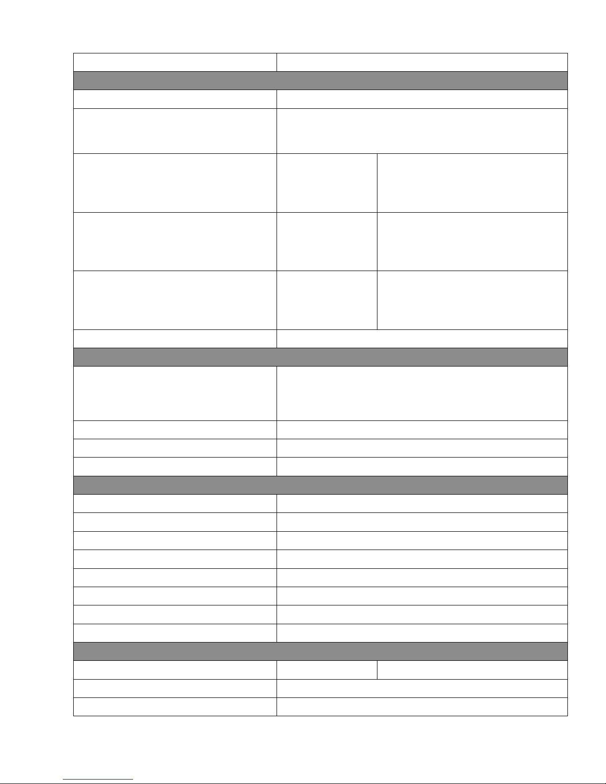
AUDIO STREAMING Yes
RECORDING
COMPRESSION TYPE H.264
RECORDING RESOLUTION
NTSC: 720 x 480/ PAL: 720 x 576
NTSC:720 x 240/ PAL: 720 x 288
NTSC: 360 x 240/ PAL: 360 x 288
RECORDING RATE (FULL D1)
NTSC: 720 x 480
up to 30 PPS
PAL: 720 x 576 up
to 25 PPS
NTSC: 720 x 480 up to 60 PPS
PAL: 720 x 576 up to 50 PPS
RECORDING RATE (HALF D1)
NTSC: 720 x 240
up to 60 PPS
PAL: 720 x 288 up
to 50 PPS
NTSC: 720 x 240 up to 120 PPS
PAL: 720 x 288 up to 100 PPS
RECORDING RATE (CIF)
NTSC: 360 x 240
up to 120 PPS
PAL: 360 x 288 up
to 100 PPS
NTSC: 360 x 240 up to 240 PPS
PAL: 360 x 288 up to 200 PPS
RECORDING MODE
Manual / Schedule / Alarm
PLAYBACK & SEARCH
PLAYBACK SPEED
Fast Forward X 2 X 4 X 8
Fast Backward X 2 X 4 X 8
field by field Playback
Pause
TIME SEARCH Yes
EVENT SEARCH Yes
EVENT LIST
3000 records per H.D.D (Maximum)
OSD & CONTROL INTERFACE
TITLE 8 Characters
ON SCREEN DISPLAY & SETUP Time / Date / Setup Menu
GRAPHIC USER INTERFACE (GUI) Yes
DVR CONTROL PANEL Yes
MOUSE Yes
IR REMOTE CONTROLLER Yes
IE BROWSER Yes
PLAYER Yes
STORAGE & BACKUP DEVICE
INTERNAL HDD SUPPORT SATA HDD x 1 SATA HDD x 2
USB PAN DRIVE BACKUP Yes
CD/ DVD RW BACKUP No
Page 7
7
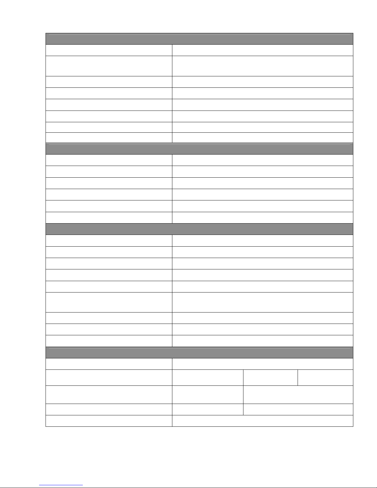
NETWORK
ETHERNET Yes
ETHERNET COMPRESSION
FORMAT
H.264
DDNS Yes
E-MAIL & FTP Yes
NETWORK IP Static/ Dynamic/ PPPoE
MULTI-REMOTE CLIENT Yes ( 4 Clients at the same time available)
PDA/ CELL PHONE SUPPORT Yes ( MPEG4 )
3GPP Yes ( MPEG4 )
ALARM
ALARM INPUT 4 In (NO/ NC)
ALARM OUTPUT 1 Out (NO/ NC)
MOTION DETECTION Yes
VIDEO LOSS DETECTION Yes
ALARM RECORDING Yes
BUZZER Yes
SETUP & OTHER FUNCTIONS
DAYLIGHT SAVING TIME Yes
PTZ CONTROL Yes
RS-232 No
RS-485 Yes
DIGITAL ZOOM Yes
PASSWORD CONTROL Two levels, one for system and the other for HDD format
KEY-LOCK Yes
MULTI-LANGUAGE Yes
FIRMWARE UPDATE USB Host & Update on line
OTHERS
POWER INPUT DC 12V
POWER CONSUMPTION 12W (without HDD)
16W (without
HDD)
22W (without
HDD)
DIMENSIONS (W x H x D)
230mm x 44mm x
215mm
360mm x 60mm x 308mm
WEIGHT (kg) 1.4(without HDD) 3.0(without HDD)
OPERATION TEMPERATURE
0 - 40 ℃
* SPECIFICATIONS ARE SUBJECT TO CHANGE WITHOUT NOTICE
Page 8
8
2 HARDWARE OVERVIEW
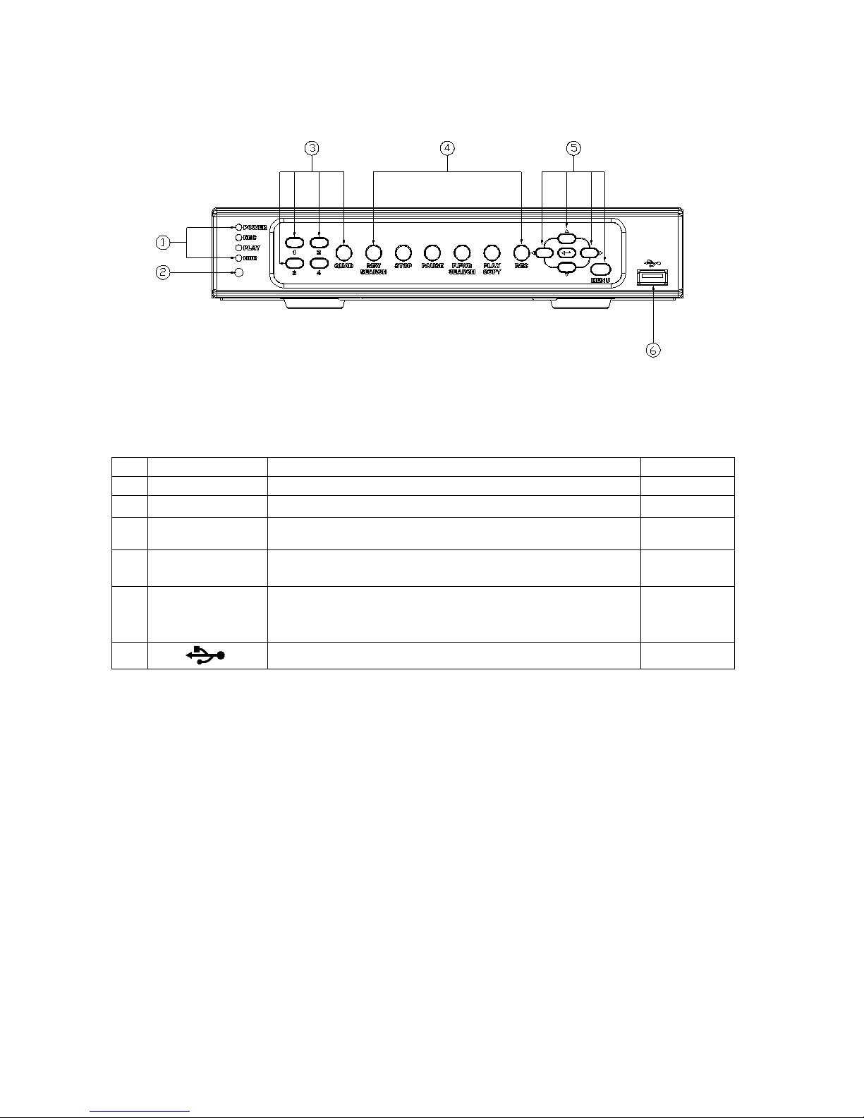
2.1 FRONT PANEL
DVR204
DVR OPERATION
NO.
LABEL OPERATION PTZ
1 LED REC
Led Indicator
2
○
○○
○ IR Sensor For Remote Control.
3 1-4 & Quad
Press The Button To Display No.1~No.4 Full Screen and
Quad Screen
4
CONTROL
PANEL
Record, Playback And other control buttons.
5
▲▼◄► &
MENU &
ENTER
Button Of Controller.
Button Of Menu Screen
Button Of Enter key
UP, DOWN,
LEFT &
RIGHT
6
USB Connector.
Page 9
9
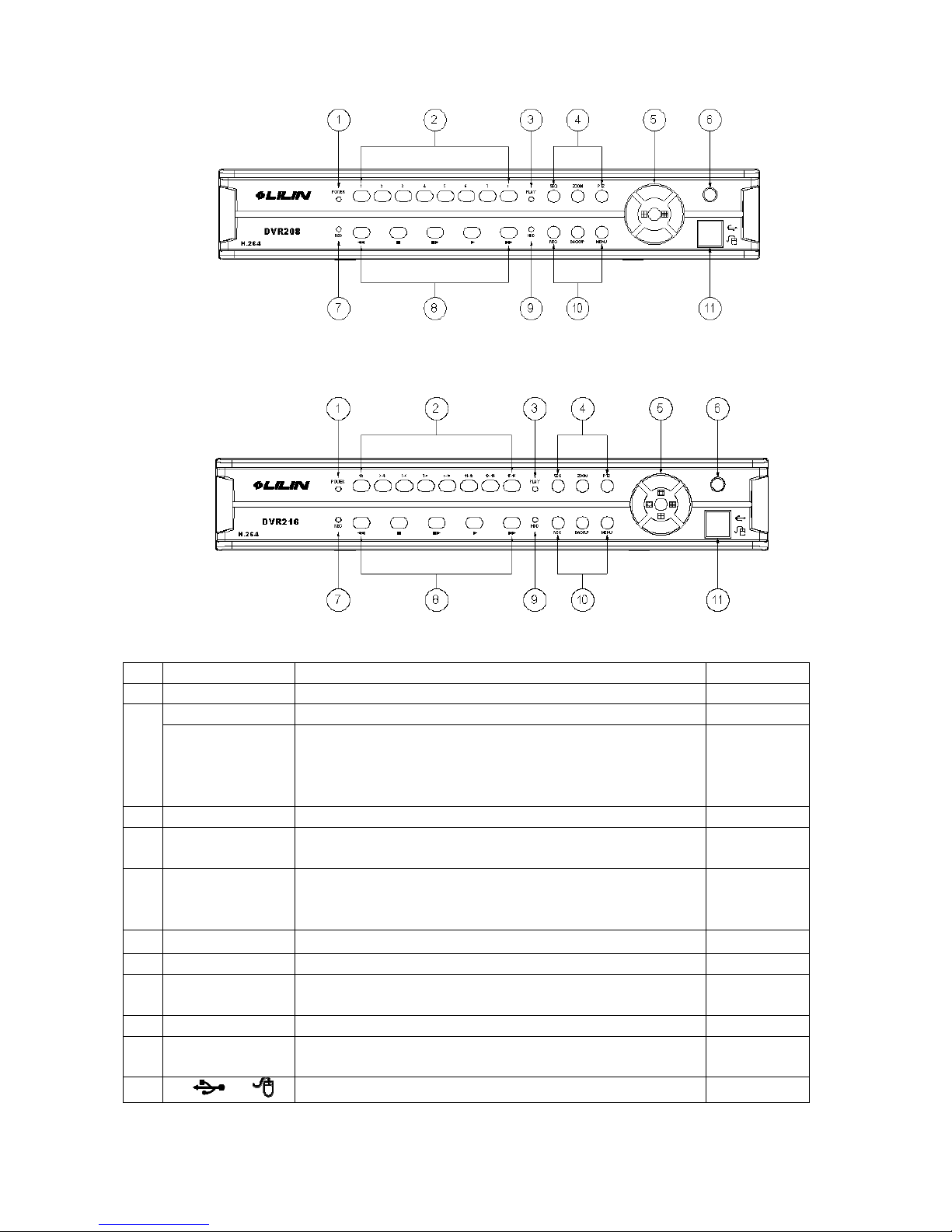
DVR208
DVR216
NO.
LABEL OPERATION PTZ
1 POWER LED
Power Led Indicator
1-8 (DVR208)
Press The Button To Display No.1~No.8
2
1-2, 3-4, 5-6,
7-8, 9-10, 11-
12,
13-14, 15-16
(DVR216)
Press The Button To Display No.1~No.16
3 PLAY LED
Play Led Indicator
4
FUNCTION
PANEL
SEQ, Zoom and PTZ buttons
5
▲▼◄► &
ENTER
Button Of Controller.
Button Of Enter key
UP, DOWN,
LEFT &
RIGHT
6
○
○○
○
IR Sensor For Remote Control
7 REC LED
Recording Led Indicator
8
CONTROL
PANEL
F.FWD, STOP, PLAY and FORWARD control buttons.
9 HDD LED
HDD Led Indicator
10
FUNCTION
PANEL
REC, BACKUP and MENU buttons
11
/
USB and Mouse (Only by supplied mouse) Connectors.
Page 10
10
2.2 BACK PANEL
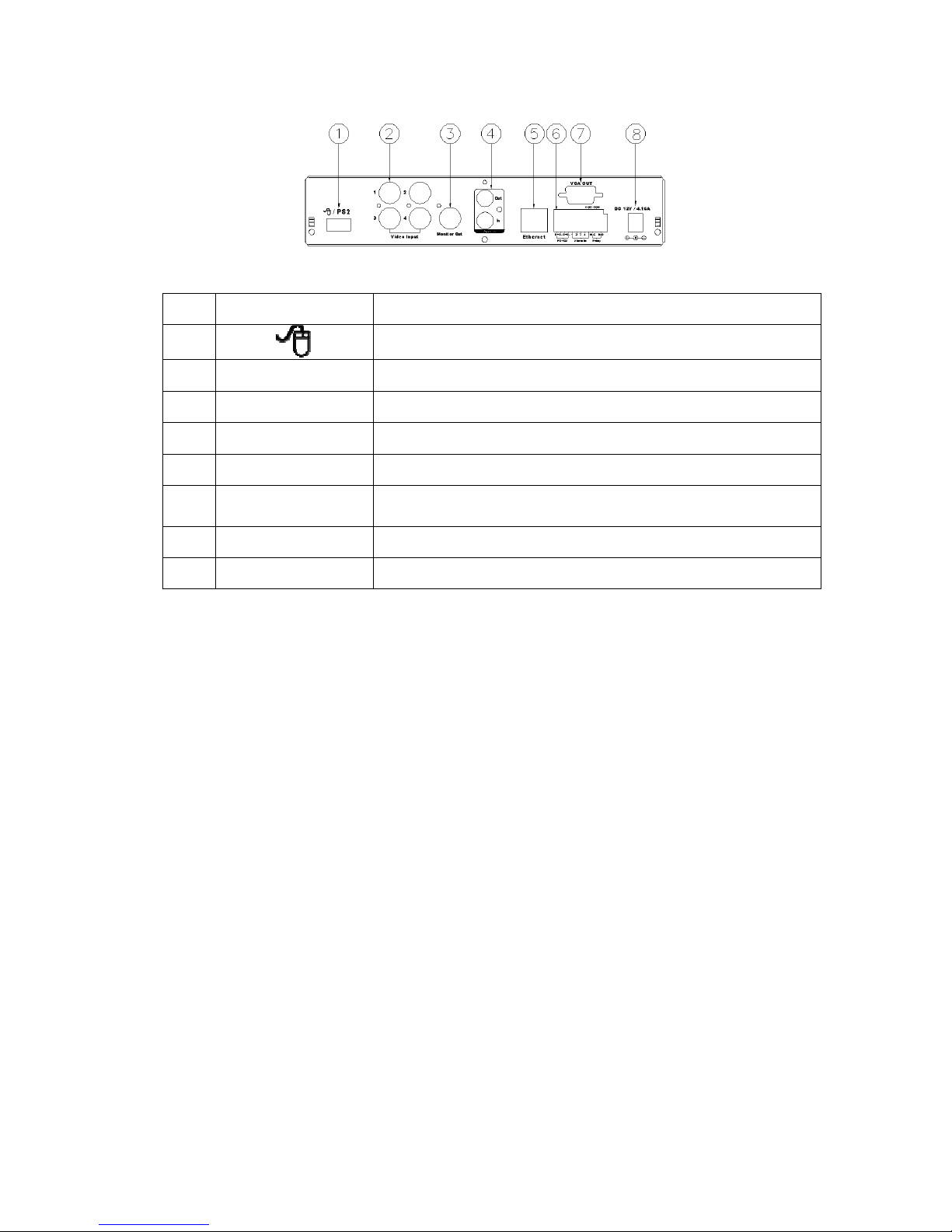
DVR204
NO.
LABEL OPERATION
1
USB Mouse Connector (Only by supplied mouse).
2 VIDEO INPUT
Video input with BNC connector.
3 MONITOR OUT
Video output with BNC connector.
4 AUDIO OUT/ IN
Audio output/ input.
5 ETHERNET
RJ-45 connector for network.
6
RS-485/ ALARM/
RELAY
4 pin connector for external control unit, 5 pin connector for
Alarm input and 3 pin connector for relay
7 VGA D-SUB OUT
Connect to CRT or LCD monitor.
8 POWER
Power switcher: DC 12V 5A / 50-60 Hz input.
NOTE: Please plug in the supplied mouse to DVR mouse connector before turn on the
DVR. DO NOT REMOVE and PLUG IN the supplied mouse while DVR is
operating.
Page 11
11
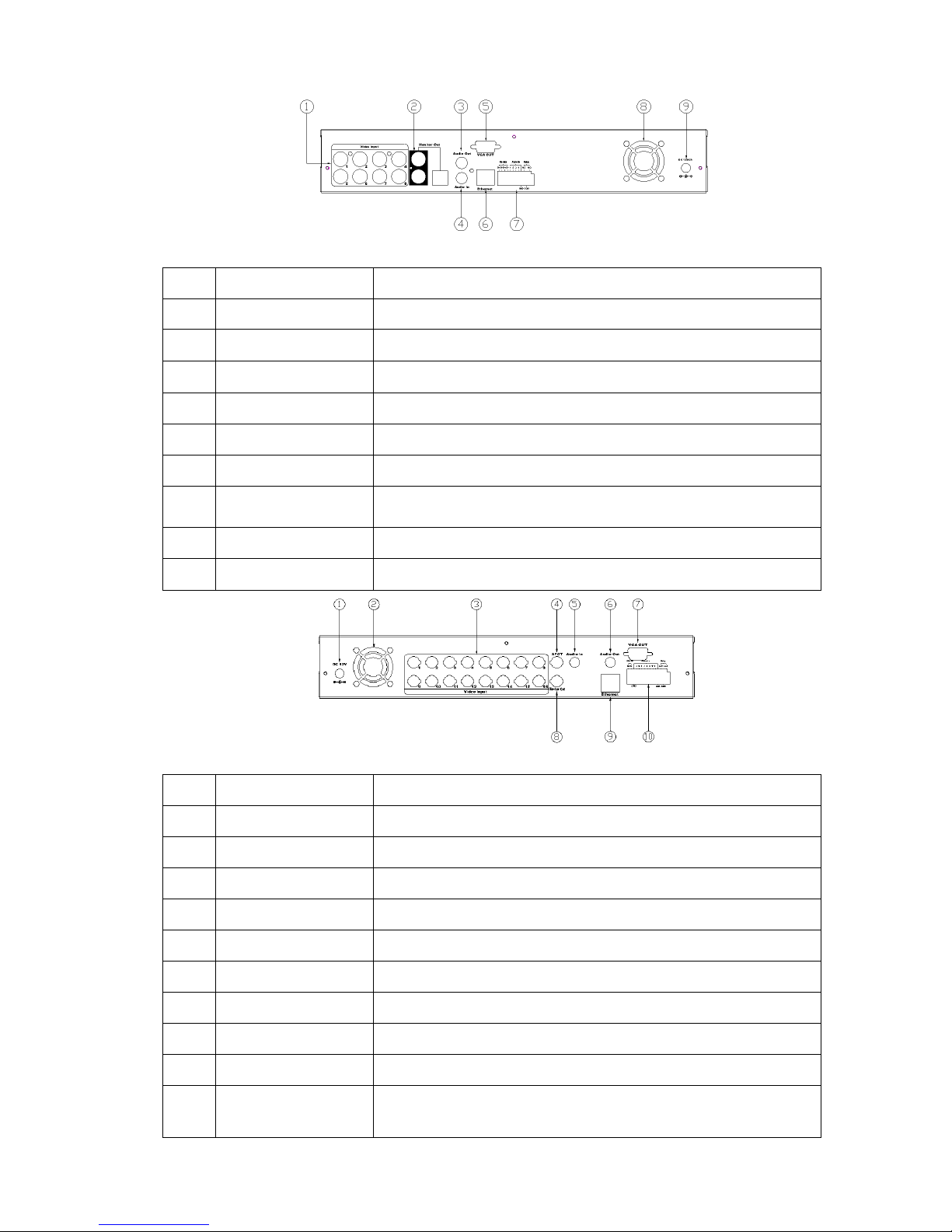
DVR208
NO.
LABEL OPERATION
1 VIDEO INPUT
Video input with BNC connector
2 MONITOR OUT
Video output with BNC connector
3 AUDIO OUT
Audio output
4 AUDIO IN
Audio input.
5 VGA D-SUB OUT
Connect to CRT or LCD monitor.
6 ETHERNET
RJ-45 connector for network.
7
RS-485/ ALARM/
RELAY
4 pin connector for external control unit, 5 pin connector for
Alarm input and 3 pin connector for relay
8 FAN
Fan
9 POWER
Power switcher: DC 12V 5A / 50-60 Hz input.
DVR216
NO.
LABEL OPERATION
1 POWER
Power switcher: DC 12V 5A input.
2 FAN
Fan
3 VIDEO INPUT
Video input with BNC connector
4 SPOT
SPOT video output.
5 AUDIO IN
Audio input.
6 AUDIO OUT
Audio output
7 VGA D-SUB OUT
Connect to CRT or LCD monitor.
8 MONITOR OUT
Video output with BNC connector
9 ETHERNET
RJ-45 connector for network.
10
RS-485/ ALARM/
RELAY
2 pin connector for external control unit, 10 pin connector
for Alarm input and 3 pin connector for relay
Page 12

12
2.3 ADVANCED AUTO SWITCH, ZOOM, PTZ, COPY KEY CONTROL & USB
INFORMATION
AUTO SWITCH : In the split screen mode, use the “F.FWD SEARCH” keys in the front
panel to enable auto switch function. Moreover, press “QUAD” key
again to disable it. (In DVR204 Module); moreover, use “SEQ”
button can also enable auto switch function. Press “SEQ” button again
can terminate auto switch function. (In DVR208/ DVR216 Module.)
PTZ : When camera supported PTZ function, user can use “F.FWD SEARCH” button on
the front panel to perform PTZ function. Press ▲▼◄► to select and change
setup value. Press “F.FWD SEARCH” again to disable PTZ function (In DVR204
Module). In DVR208/ DVR216 module, use “PTZ” button on the front panel can
enable PTZ function and then press “PTZ” button again to disable PTZ function.
COPY : Within the playback mode, press “ PLAY COPY ” button to start backup record
and press “ PLAY COPY ” again to end backup(DVR204 Module). The user
can see the backup image approx. 3 ~5 sec. In DVR208/DVR216 Module, press
“Backup” button to start backup and then press it again to end backup function.
2.4 EXTERAL ALARM
There are three types of alarms that the system can be configured to handle. They are
Motion detection Alarm, External Alarm and Video Loss Alarm.
A. Motion detection Alarm and External Alarm:
When motion detection or External Alarm was triggered, there are 5 possible actions
will be taken.
a. Changes recording speed as alarm recording speed.
b. Monitor will display corresponding full screen alarm channel, it will switch
automatic mode to manual mode if buttons pressing activity occurred in 5 seconds.
c. Relays can be activated by motion detection or external alarm when turning on.
d. The camera title will be transformed into color of yellow when motion is happening,
“ALARM” text will show up when external alarm is triggered.
B. Video Loss Alarm:
The default setting of Video Loss alarm is enabled.
Page 13
13
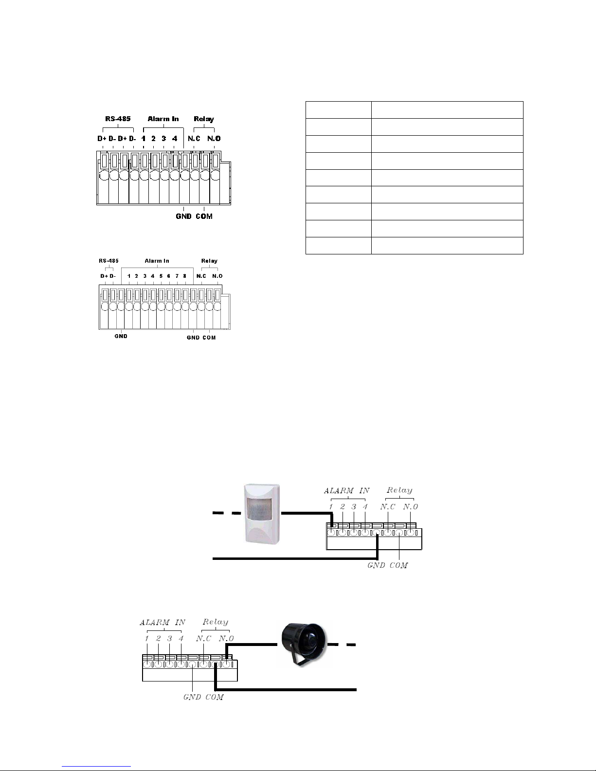
Terminal Connectors:
EXAMPLE 1:Connect Alarm In One with PIR (Passive Infrared).
EXAMPLE 2:Connect with Alarm Siren at Relay N.O.
D+ RS-485 sends +/ receives +
D - RS-485 sends -/ receives D+ RS-485 sends +/ receives +
D - RS-485 sends -/ receives ALARM1-4 Camera alarm input.
GND GND.
N.C Relay N.C.
COM
Relay COM
N.O Relay N.O.
(DVR204/ DVR208)
(DVR216)
Page 14
14
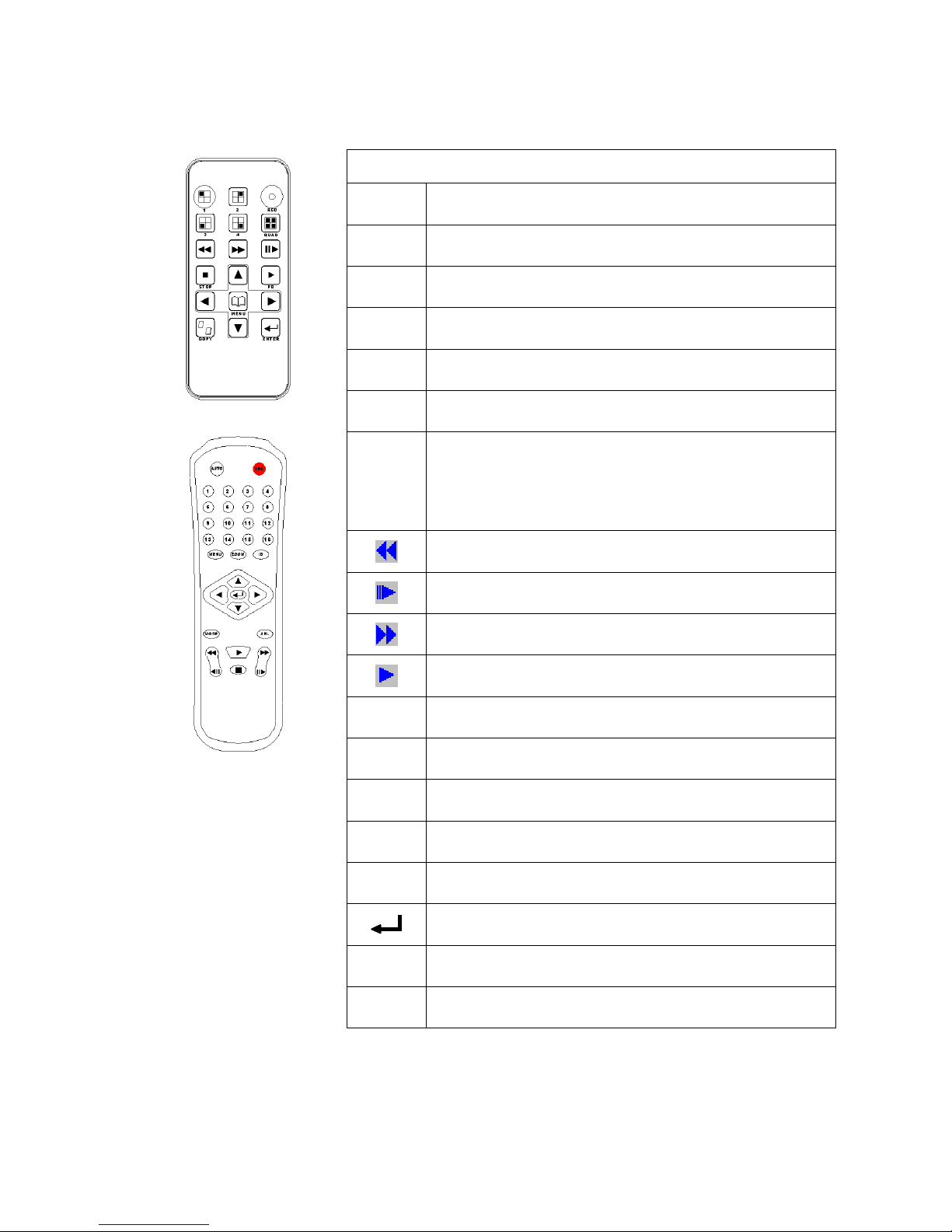
2.5 IR REMOTE CONTROL
ITEM
REC
Press REC to start recording and press twice to stop.
AUTO
Press AUTO to activate sequence display of channels
(DVR208/DVR216 USE ONLY)
1 - 4
Select channel 1-4 with full screen. (DVR204 USE
ONLY)
1-16
Select channel 1-16 with full screen. (DVR208/
DVR216 USE ONLY)
QUAD
Fast backward. (DVR204 USE ONLY)
MODE
Split Screen Switch (DVR208/ DVR216 USE ONLY)
SEL
Press this button to select the different assembled of
camera formats or perform PTZ functions. Moreover,
under the 16 split screen and full screen modes, press
this button for switching Audio ON/ OFF. (DVR208/
DVR216 USE ONLY)
Picture by picture backward.
Picture by picture forward.
Fast Forward.
Play video forward.
COPY
Switch channel format. (DVR204 USE ONLY)
▲
Move upward or increase the number.
►
Move rightward or increase the number.
▼
Move downward or decrease the number.
◄
Move leftward or decrease the number.
Enter selected items.
MENU
Enter or Exit Main Menu.
(DVR204)
(DVR208/DVR216)
STOP
Stop the playback.
Page 15
15
3 SYSTEM SETUP
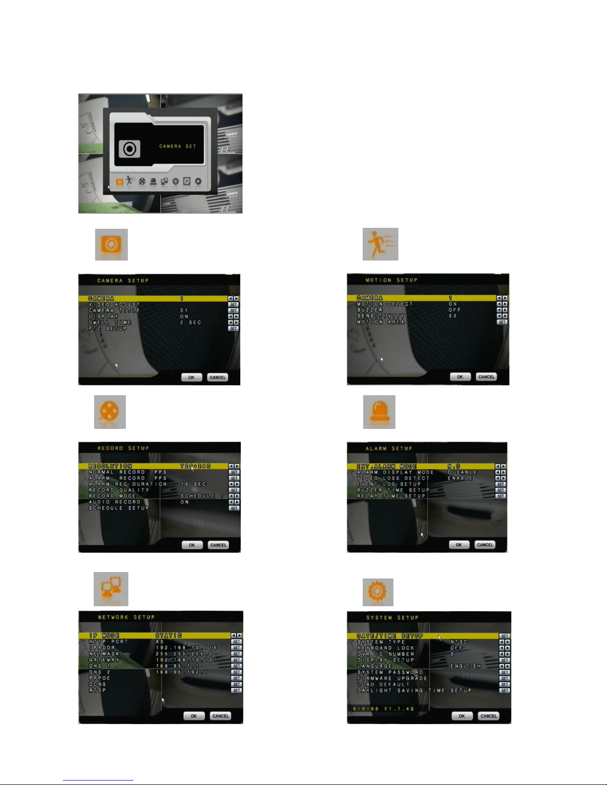
3.1 MENU SETUP INTERFACE(GUI)
A. CAMERA SET B. MOTION SETUP
C. RECORD SETUP D. ALARM SETUP
E. NETWORK SETUP F. SYSTEM SETUP
Page 16
16
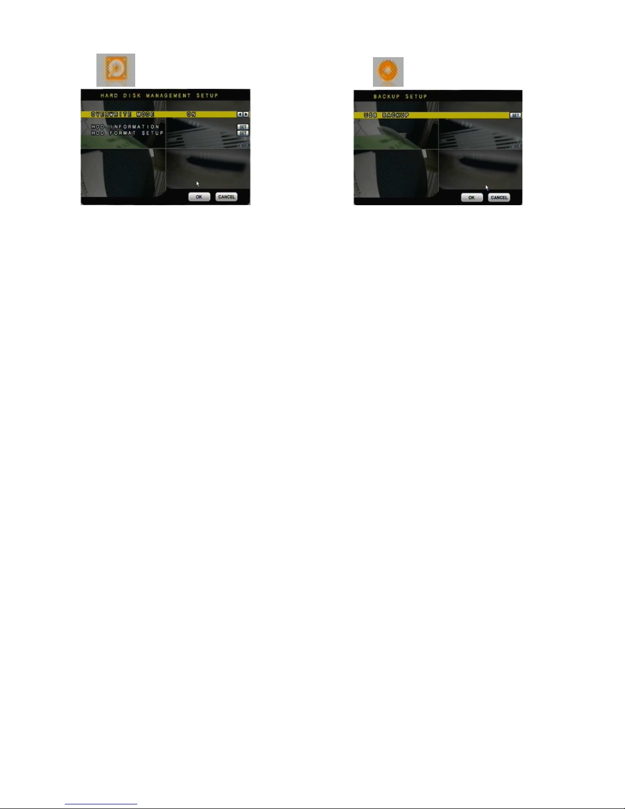
G. HARD DISK SETUP H. BACKUP SETUP
Page 17
17
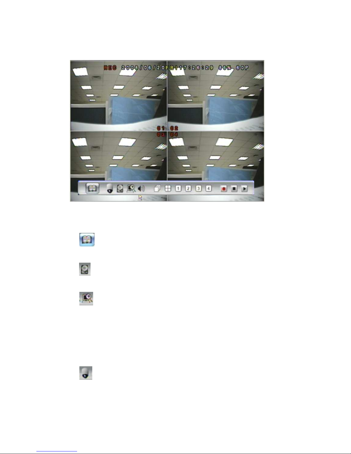
3.2 LIVE VIEWING AND POP-UP MENU
NOTE::::All of the images and icons are presented by DVR204 Module.
NOTE::::The pop-up menu can be activated by moving the mouse cruise to the bottom
of the live viewing screen.
A. GUI MENU BAR
With live viewing mode, press this button to get into the GUI menu.
B. DISK INFORMATION
With live viewing mode, press this button to display disk information.
C. DIGITAL ZOOM
In the full screen mode, left-click the button of the mouse to pull a range to zoom in or
zoom out the image. User can right-click the button of the mouse to disable this
function. (NOTE: Using the mouse to operate digital zoom can zoom in to max. 16
times.) Moreover, user can also use compound key on the front panel to perform this
function. (First, click ENTER/COPY Key and then click ▲▼◄► key to select zoom
in or zoom out position. Finally, click ENTER/COPY key again to complete the setting.
Moreover, click MENU Key to disable digital zoom function. Using the panel key to
perform zoom in function is fixed at 2 times.)
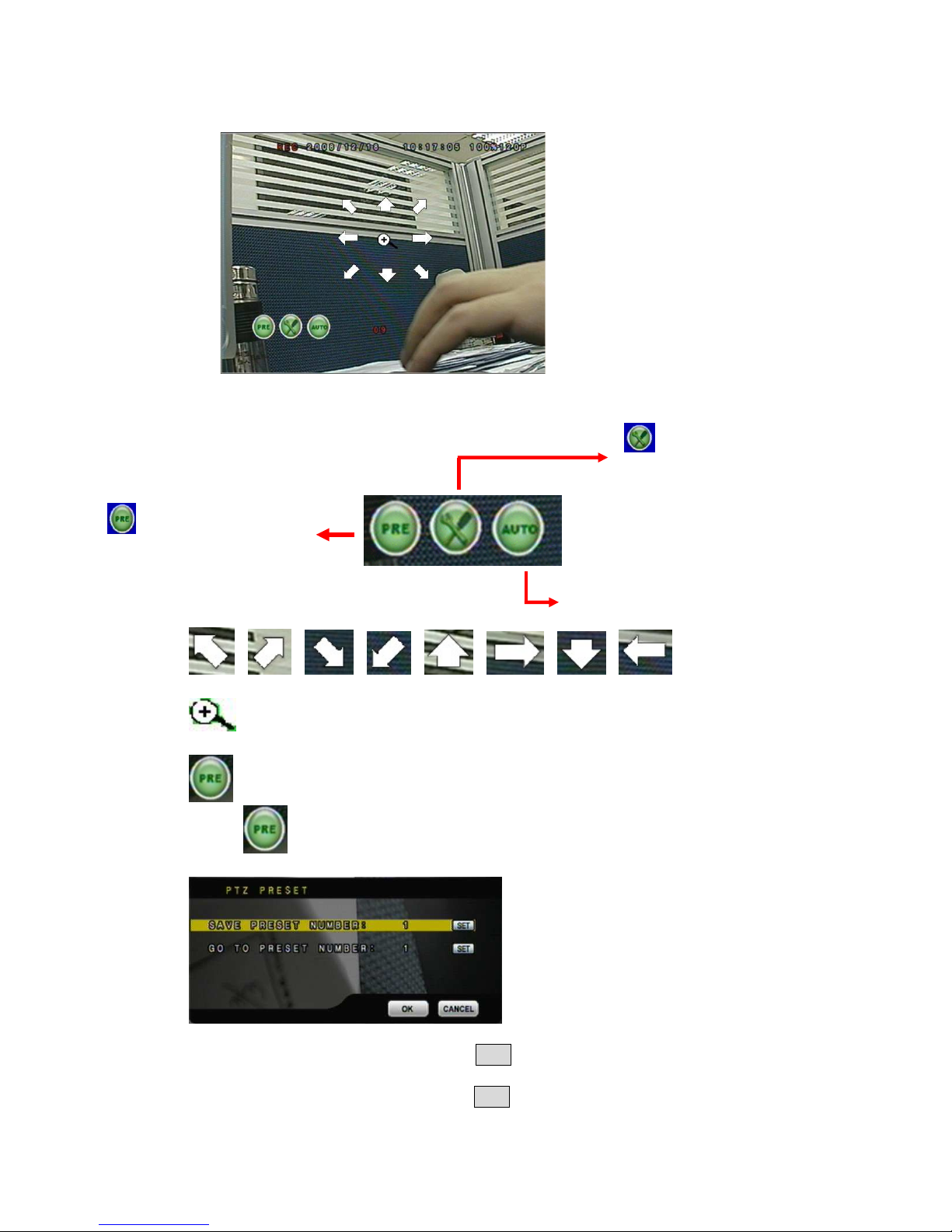
D. PTZ CONTROLLER
Within live-viewing mode, Clicks this button to get into the PTZ setup menu. User
can also use PTZ key on the front panel to perform this function. Moreover, user can
right-click the button of the mouse or press the PTZ key on the front panel again to
exit PTZ Setup.
NOTE
:
::
: Only for the camera supported PTZ function.
Page 18
18
PTZ CONTROL
/ / / / / / / Direction key
Zoom In/ Zoom Out
PTZ Preset
Press button to entry PTZ preset point menu.
SAVE PRESET NUMBER: Press SET to save preset point number and its
position.
GO TO PRESET NUMBER: Press SET to go to the setup preset point number
position.
Under PTZ control mode, press
into PTZ setup menu.
User can also press the “MENU”
key on the DVR front panel to get
into PTZ setup menu.
Press to process Preset Point
setup and press “■■■■” to exit setup
To process AUTO function.
Page 19
19
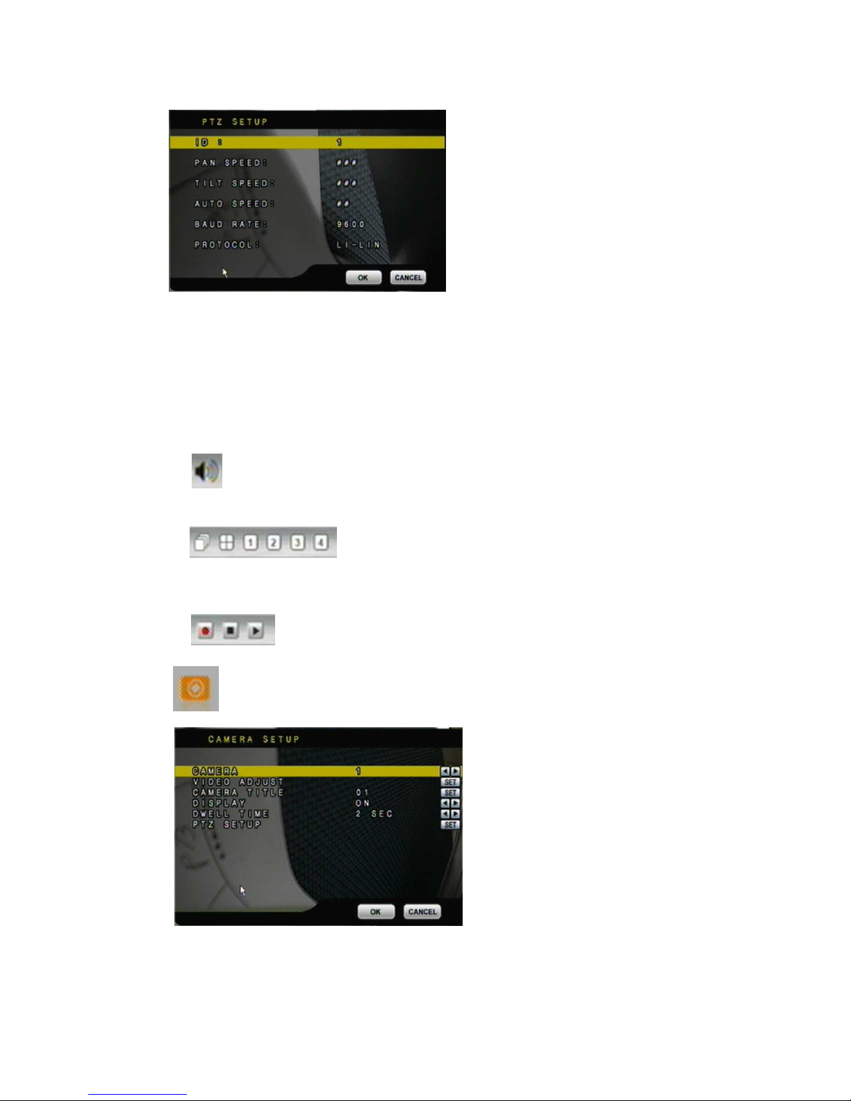
PTZ SETUP MENU
ID : Use the mouse wheel to setup the PTZ camera ID number.
PAN SPEED: Use the mouse wheel to change the left-right speed.
TILT SPEED: Use the mouse wheel to change the up-down speed.
AUTO SPEED: Use the mouse wheel to change the auto patrol speed.
BAUD RATE: Use the mouse wheel to change the BAUD rate.
PROTOCOL: Use the mouse wheel to change the connection protocol.
E. AUDIO CONTROL
Press this button to turn the audio on or off.
F. DISPLAY CONTROL
Within live-viewing or playback mode, use display control to switch the camera
channel.
G. RECORD AND PLAYBACK CONTROL
Same as front panel controller and remote controller.
3.3 CAMERA SETUP
Press ▲ or ▼ to select items.
Press ◄ or ► to change values.
Press SET to see more options.
A. CAMERA
Press ◄ or ►/ mouse wheel to switch channels.
Page 20
20
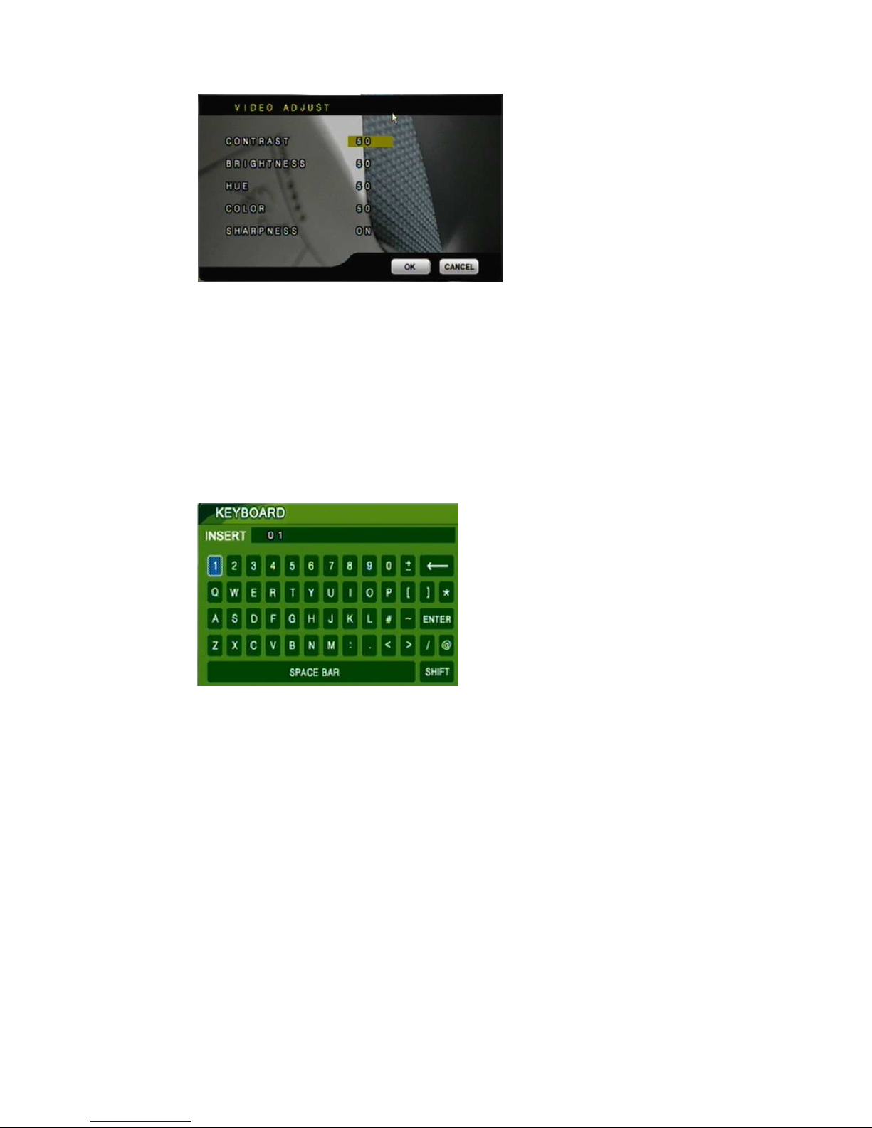
B. VIDEO ADJUST
B-1. CONTRAST
Press ◄ or ►/ mouse wheel to change contrast level.
B-2. BRIGHTNESS
Press ◄ or ►/ mouse wheel to change brightness level.
B-3. HUE
Press ◄ or ►/ mouse wheel to change HUE level.
B-4. COLOR
Press ◄ or ►/ mouse wheel to change color level.
B-5. SHAPRNESS
Press ◄ or ►/ mouse wheel to change sharpness level.
C. CAMERA TITLE
Use mouse to select and change character.
D. DISPLAY
Press ◄ or ► to/ mouse wheel change value for the corresponding camera would be
displayed on the screen or not.
E. DWELL TIME
Press ◄ or ►/ mouse wheel to ON/OFF auto switch and the switch sec..
Page 21
21
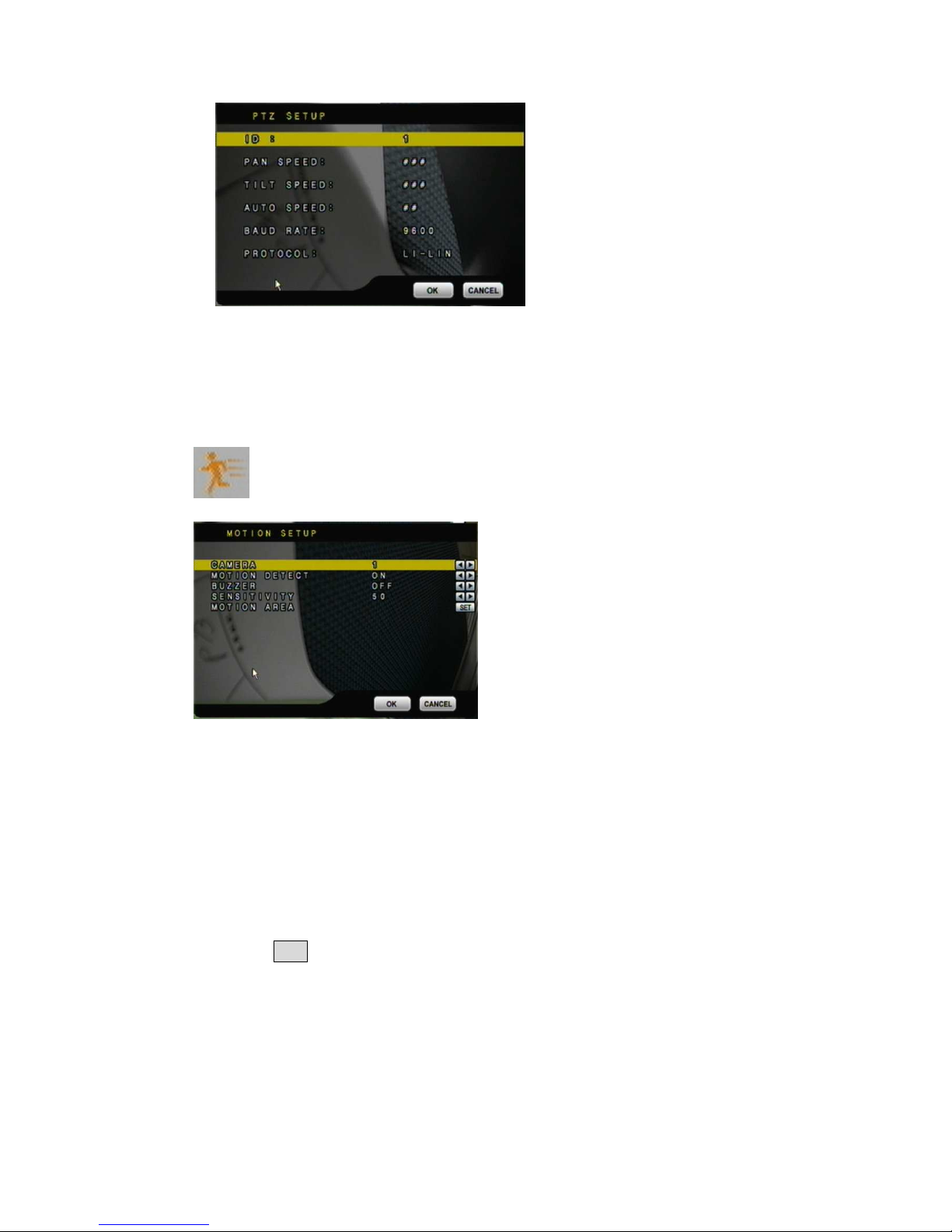
F. PTZ SETUP
ID : Use the mouse wheel to setup the PTZ camera ID number.
PAN SPEED: Use the mouse wheel to change the left-right speed.
TILT SPEED: Use the mouse wheel to change the up-down speed.
AUTO SPEED: Use the mouse wheel to change the auto patrol speed.
BAUD RATE: Use the mouse wheel to change the BAUD rate.
PROTOCOL: Use the mouse wheel to change the connection protocol.
3.4 MOTION SETUP
A. CAMERA
Press ◄ or ►/ mouse wheel to switch channels.
B. MOTION DETECT
Press ◄ or ►/ mouse wheel to change value for motion detect function.
C. BUZZER
Press ◄ or ►/ mouse wheel to change value for buzzer while motion detected.
D. SENSITIVITY
Press ◄ or ►/ mouse wheel to change sensitivity value from 001 (minimum) to 100
(maximum).
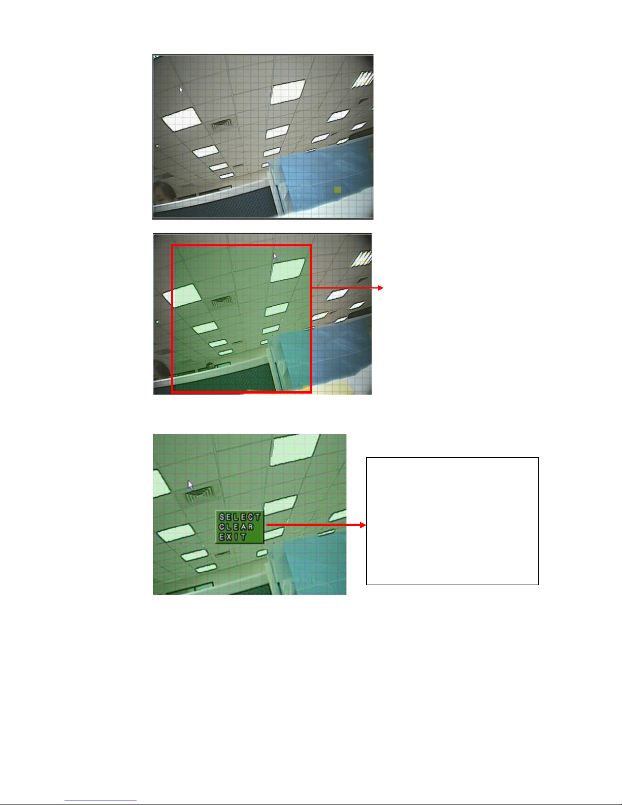
E. MOTION AREA SETUP
1. Press SET to enter Motion Area Setting. (Note: The default setting of all area is
“MOTION ON”.)
Press ▲ or ▼ to select items.
Press ◄ or ► to change values.
Press SET to see more options.
Page 22
22
2. Use the mouse to select which block is needed.
3. Left-Click the mouse to see more options or exit the setup.
The green area shows the area
without motion detection.
SELECT: Cancel the selected
area.
CLEAR: Select the area without
motion detection.
EXIT: Exit the motion detection
setup.
Page 23
23
3.5 RECORD SETUP
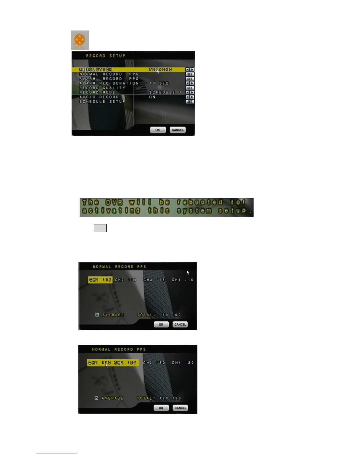
A. RESOULTION
Press ◄ or ►/ mouse wheel to switch record resolution.
FULL D1: 720 x 480 (NTSC)/ 720 x 576 (PAL)
HALF D1: 720 x 240 (NTSC)/ 720 x 288 (PAL).
CIF: 360 x 240 (NTSC)/ 360 x 288 (PAL).
NOTE: If record resolution is altered in here, DVR will reboot automatically.
B. NORMAL RECORD PPS
Press SET to change the PPS in normal recording. User can click “AVERAGE” to set
PPS automatically by system or change the PPS for each channel manually.
Record Resolution: FULL D1: 720 x 480 (NTSC)/ 720 x 576 (PAL)
HALF D1: 720 × 240 ( NTSC ) / 720 × 288 ( PAL )
Record Resolution: CIF: 360 × 240 ( NTSC ) / 360 × 288 ( PAL )
Press ▲ or ▼ to select items.
Press ◄ or ► to change
values.
Press SET to see more options.
Page 24
24
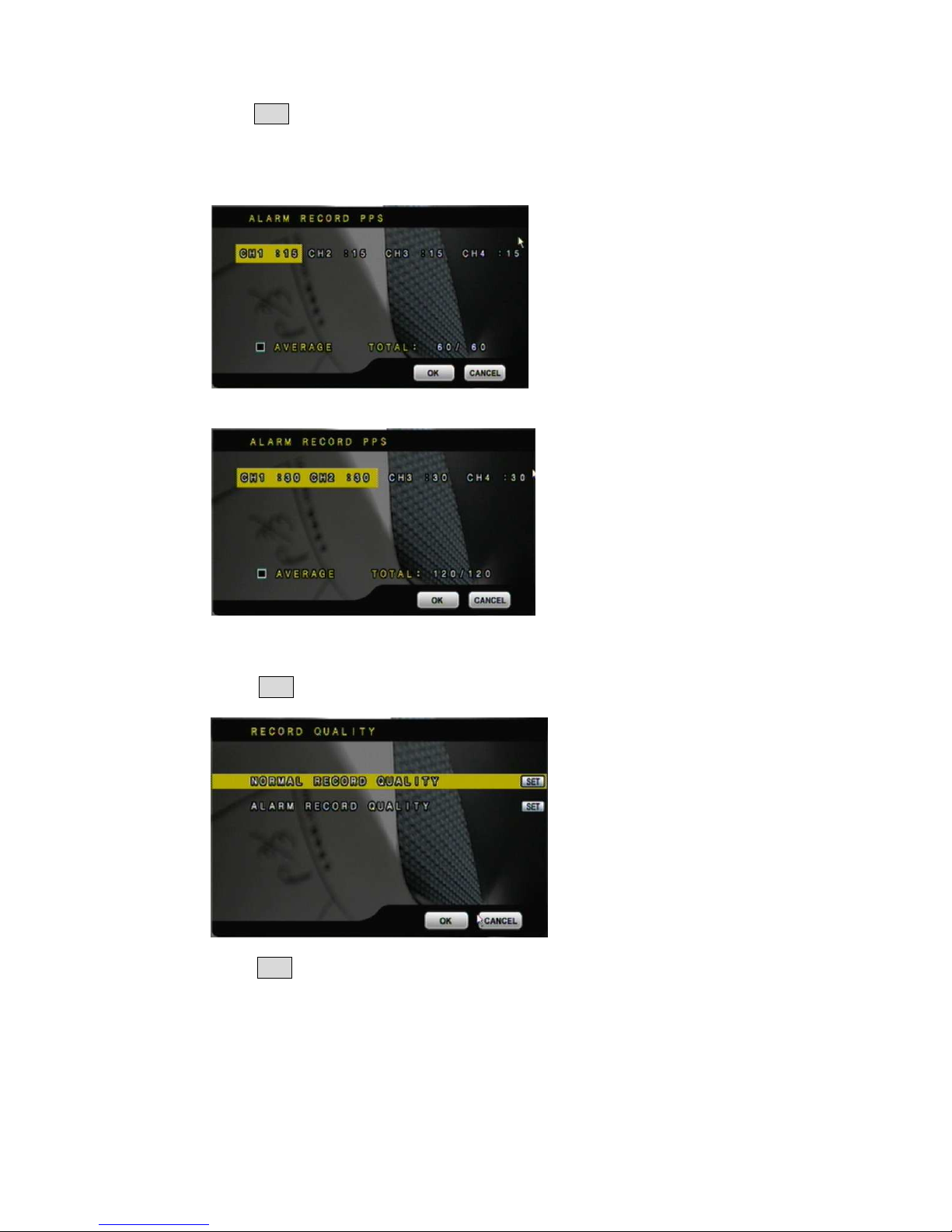
C. ALARM RECORD PPS
Press SET to change the PPS in alarm recording. User can click “AVERAGE” to set
PPS automatically by system or change the PPS for each channel manually.
Record Resolution: FULL D1: 720 x 480 (NTSC)/ 720 x 576 (PAL)
HALF D1: 720 × 240 ( NTSC ) / 720 × 288 ( PAL )
Record Resolution: CIF: 360 × 240 ( NTSC ) / 360 × 288 ( PAL )
D. ALARM RECORD DURATION
Press ◄ or ► to set dwell time of alarm recording.
E. RECORD QUALITY
Press SET to entry to the record quality setup. There are NORMAL RECORD
QUALITY and ALARM RECORD QUALITY two items can be set.
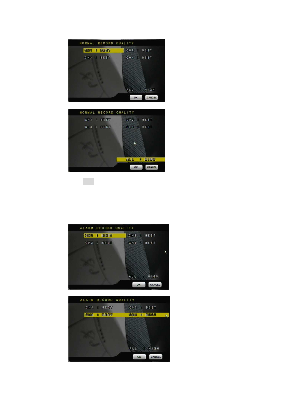
E-1. NORMAL RECORD QUALITY
Press SET to switch normal record quality of each channel (FULL D1: 720 × 480
( NTSC ) / 720 × 576 ( PAL ), HALF D1: 720 × 240 ( NTSC ) / 720 × 288 ( PAL )) or
each two channels (360 × 240 ( NTSC ) / 360 × 288 ( PAL )). User can use mouse
wheel to change the image quality of each single channel: LOW/ MEDIUM/ HIGH/
BEST, or use “ALL” to switch the image quality of all channels at once.
Page 25
25
Record Resolution: FULL D1: 720 x 480 (NTSC)/ 720 x 576 (PAL)
HALF D1: 720 × 240 ( NTSC ) / 720 × 288 ( PAL )
Record Resolution: CIF: 360 × 240 ( NTSC ) / 360 × 288 ( PAL )
E-2. ALARM RECORD QUALITY
Press SET to switch alarm record quality of each channel (FULL D1: 720 × 480
( NTSC ) / 720 × 576 ( PAL ), 720 × 240 ( NTSC ) / 720 × 288 ( PAL )) or each two
channels (360 × 240 ( NTSC ) / 360 × 288 ( PAL )). User can use mouse wheel to
change the image quality of each single channel: LOW/ MEDIUM/ HIGH/ BEST, or
use “ALL” to switch the image quality of all channels at once.
Record Resolution: FULL D1: 720 x 480 (NTSC)/ 720 x 576 (PAL)
HALF D1: 720 × 240 ( NTSC ) / 720 × 288 ( PAL )
Record Resolution: CIF: 360 × 240 ( NTSC ) / 360 × 288 ( PAL )
Page 26
26
F. RECORD MODE
Press ◄ or ► to switch record mode to MANUAL/ SCHEDULE 1 / SCHEDULE 2/
SCHEDULE 3/ SCHEDULE 4/ SCHEDULE 5
G. AUDIO RECORD
Press ◄ or ► to switch AUDIO RECORD ON or OFF.
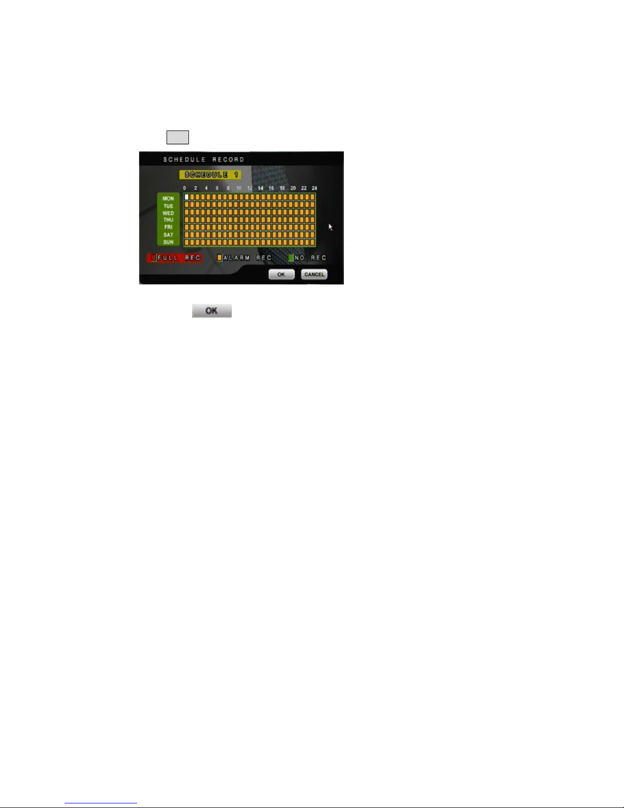
H. SCHEDULE SETUP
Press SET to get into schedule setup menu。
1. Use mouse to select schedule day/ time/ mode.
2. Click to save change and exit.
Page 27
27
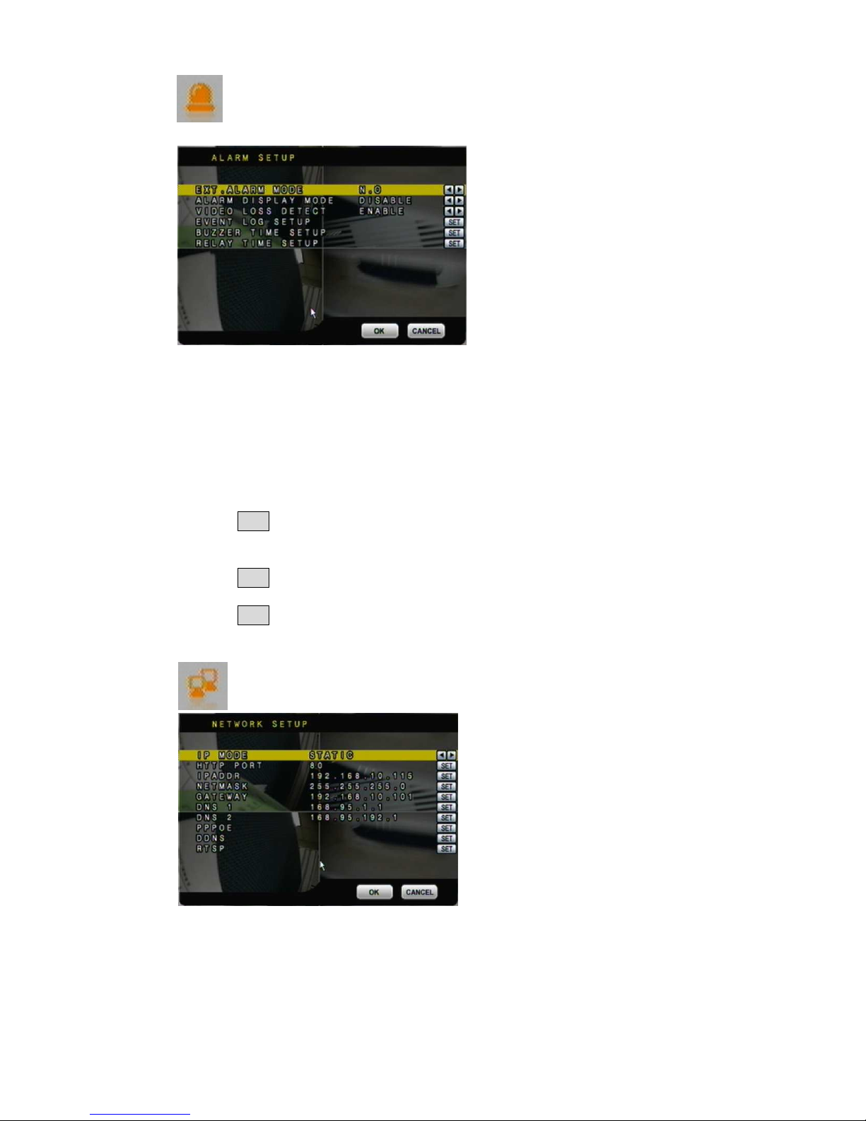
3.6 ALARM SETUP
Press ▲ or ▼ to select items.
Press ◄ or ► to change values.
Press SET to see more options.
A. EXT. ALARM MODE
Select N.C for “normal close” alarm input, or select N.O for “normal open” alarm
input.
B. ALARM DISPLAY MODE
Press ◄ or ►/ mouse wheel to change value for ALARM DISPLAY MODE with full
screen.
C. VIDEO LOSS DETECT
Press ◄ or ►/ mouse wheel to switch VIDEO LOSS ALARM ON or OFF.
D. EVENT LOG SETUP
Press SET to change value for MOTION EVENT / VIDEO LOSS EVENT to ON /
OFF.
E. BUZZER TIME SETUP
Press SET to set dwell time of BUZZER/ ALARM.
F. RELAY TIME SETUP
Press SET to set dwell time of RELAY.
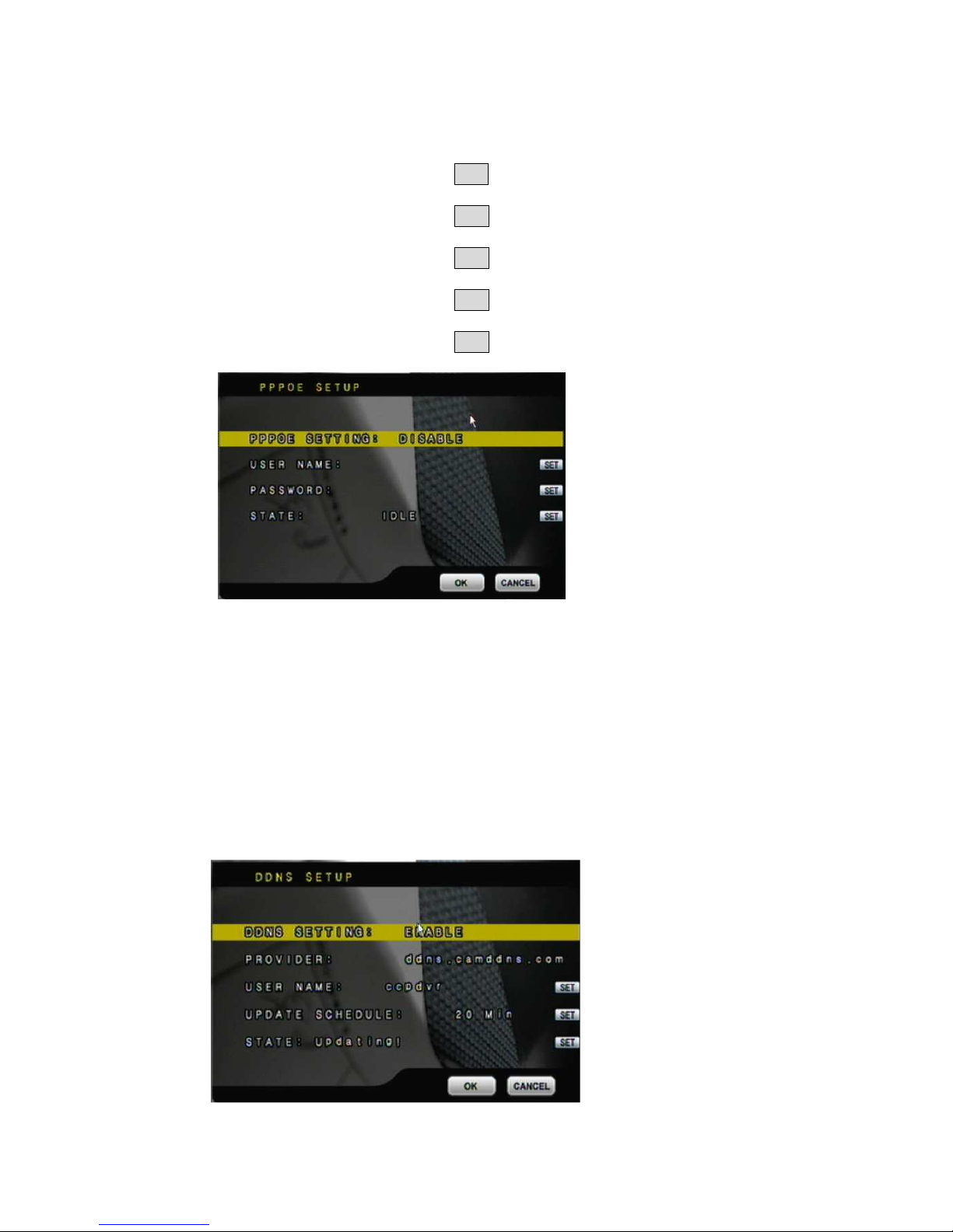
3.7 NETWORK SETUP
A. IP MODE
Press ▲ or ▼ to select items and ◄ or ►/ mouse wheel to change to STATIC IP or
DHCP.
Press ▲ or ▼ to select items.
Press ◄ or ► to change values.
Press SET to see more options.
Page 28
28
B. HTTP PORT
Press ▲ or ▼ to select items and ◄ or ►/ mouse wheel to change WEB PAGE
PORT.
C. IP ADDR
Press ▲ or ▼ to select items and SET to change IP ADDRESS.
D. NETMASK
Press ▲ or ▼ to select items and SET to change SUBNET MASK.
E. GATEWAY
Press ▲ or ▼ to select items and SET to change Default GATEWAY.
F. DNS1
Press ▲ or ▼ to select items and SET to change DNS.
G. DNS2
Press ▲ or ▼ to select items and SET to change OTHER DNS.
H. PPPoE
H-1. PPPoE SETTING
Press◄ or ►/ mouse wheel to ENABLE / DISABLE PPPoE.
H-2. USER NAME
Use mouse to setup user name for ADSL account.
H-3. PASSWORD
Use mouse to setup password for ADSL account.
H-4. STATE
Press SET to display status of PPPoE。
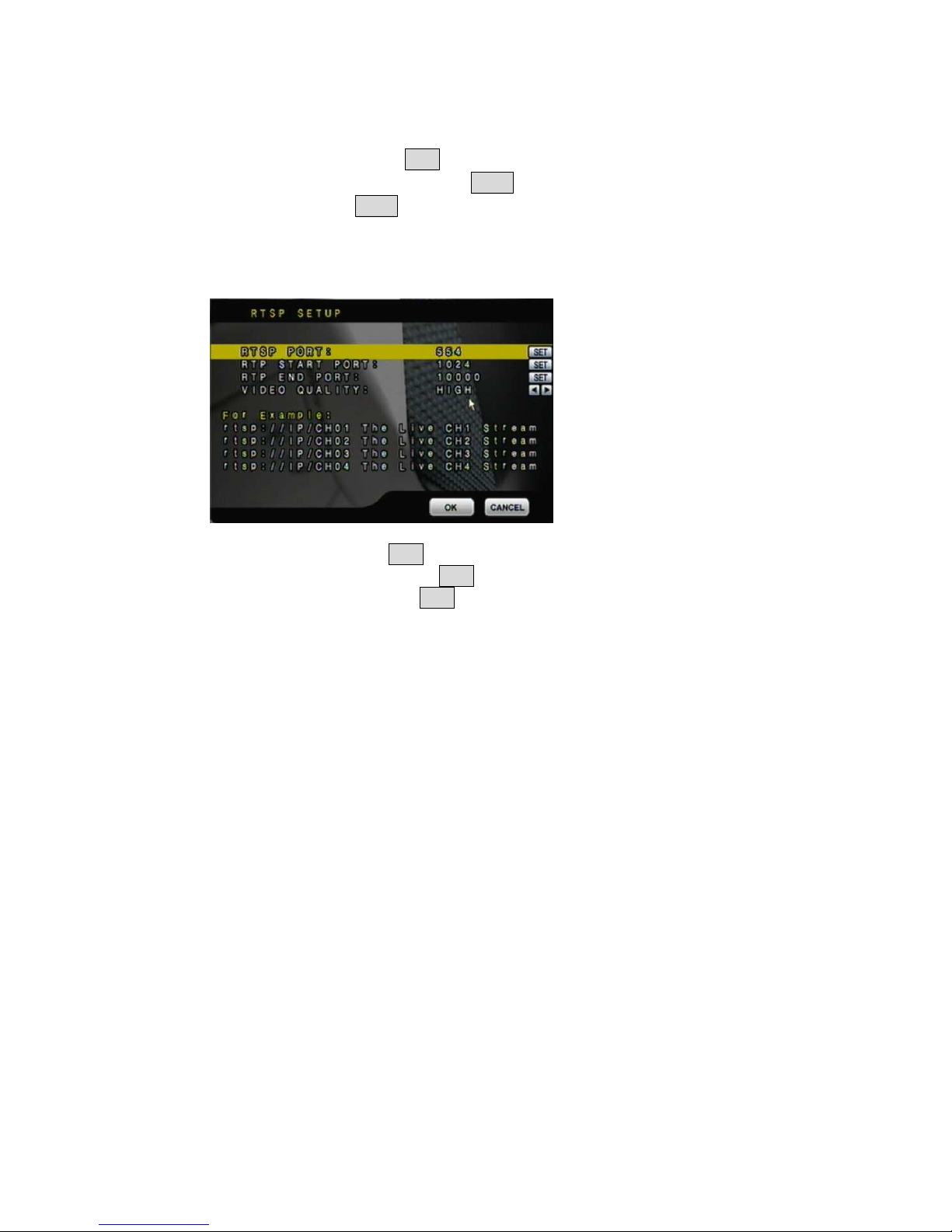
I. DDNS SETUP
Page 29
29
I-1. DDNS SETTING::::Press◄ or ►/ mouse wheel to set DDNS ENABLE /
DISABLE.
I-2. PROVIDER::::Press◄ or ►/ mouse wheel to select DDNS provider.
I-3. USER NAME::::Press SET to setup user name.
I-4. UPDATE SCHEDULE:::: Use SET to dwell time of updating schedule.
I-5. STATE::::Press SET to display status of DDNS.
J. RTSP SETUP
J-1. RTSP PORT: Press SET to setup RTSP port. The default value is 554.
J-2. RTP START PORT: Press SET to setup RTP start port.
J-3. RTP END PORT: Press SET to setup RTP end port.
J-4. VIDEO QUALITY: Press◄ or ►/ mouse wheel to select video quality. There are
BEST, HIGH, STANDARD, MEDIUM & LOW five options.
Page 30
30
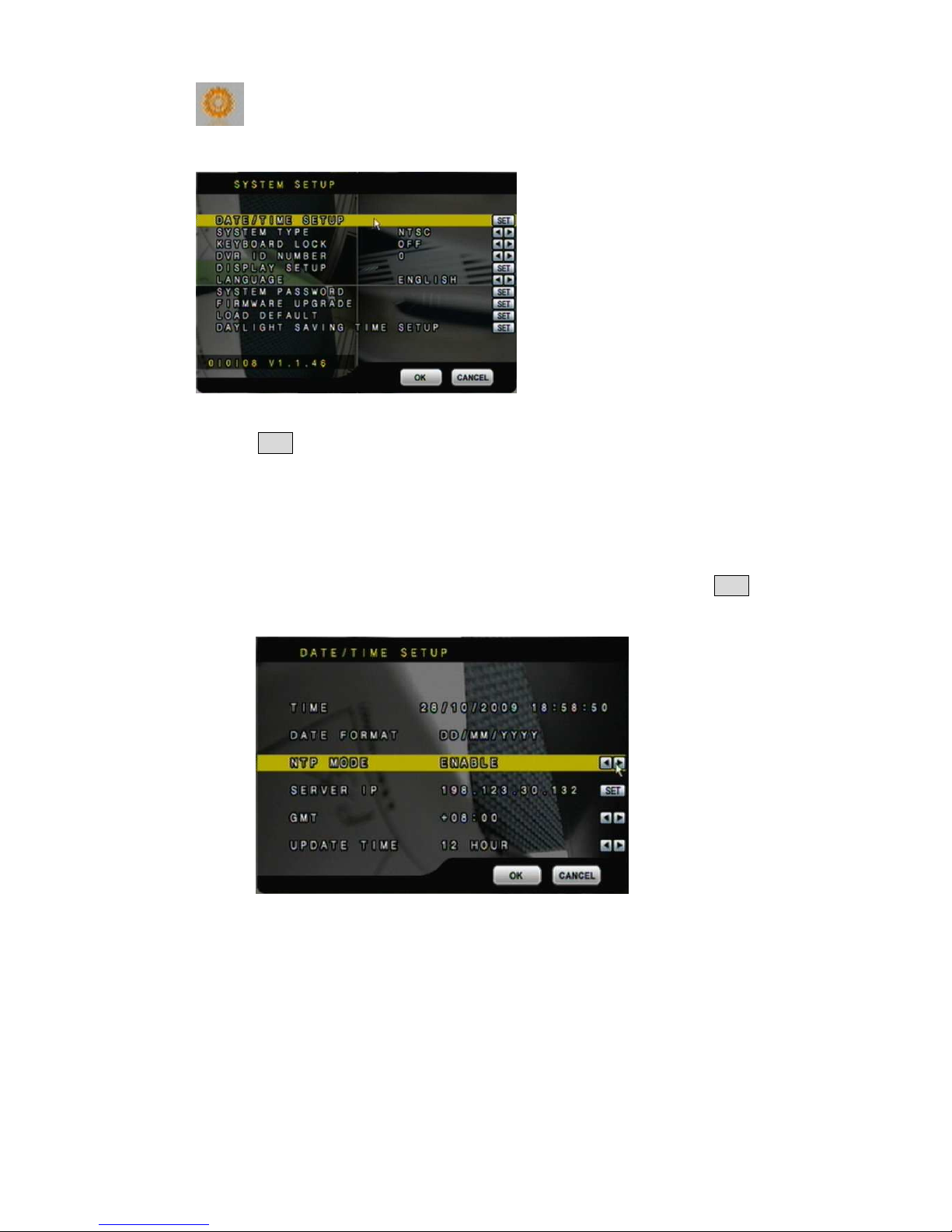
3.8 SYSTEM SETUP
Press ▲ or ▼ to select items.
Press ◄ or ► to change values.
Press SET to see more options.
A. DATE / TIME SETUP
Press SET to set DATE / TIME.
A-1. TIME
Use mouse wheel to change DATE/ TIME.
A-2. DATE FORMAT
Use mouse wheel to change DATE. There are DD/MM/YYYY, YYYY/MM/DD
and MM/DD/YYYY three modes.
A-3. NTP MODE
Use mouse wheel to change NTP. When NTP is enable, use SET to change
SERVER IP and use ◄ or ►/ mouse wheel to change GMP and UPDATE
TIME.
B. SYSTEM TYPE
Press ◄ or ►/ mouse wheel to change the system type. Moreover, DVR will reboot
while changing the system type.
C. KEYBOARD LOCK
Press ◄ or ►/ mouse wheel to switch ON/ OFF. There are OFF, TYPE 1 and TYPE 2
three options.
OFF:UNLOCK.
TYPE 1: Only can switch split screen and full screen. The user can operate AUTO
and MENU functions as well. However, the password has to be filled in to
implement playback mode.
Page 31
31
TYPE 2: LOCK (Except MENU button). The password has to be filled in to
implement playback mode.
After KEYBOARD LOCK mode setup, please set up PASSWORD
Without password, un-authorized users could access into SYSTEM SETUP and make
changes of settings easily.
D. DVR ID NUMBER
Press ◄ or ►/ mouse wheel to change values.
ID NUMBER is required to make difference of each DVR.
E. DISPLAY SETUP
Press SET to ENABLE or DISABLE display of CAMERA TITLE / DVR STATUS /
DATE / TIME.
F. LANGUAGE
Press ◄ or ► to change on-screen-display (OSD) language.
G. SYSTEM PASSWORD
Press ▲ or ▼ to select items and ◄ or ► to change values.
Default password: 1111.
H. FIRMWARE UPDATE
Press YES to start firmware update. After updated, the DVR will reboot automatically.
At this moment, please do not turn off the DVR manually.
NOTE: 1. Please format USB flash memory with FAT32.
2. For function stability, we suggest user to STOP recording function
before processing firmware update function.
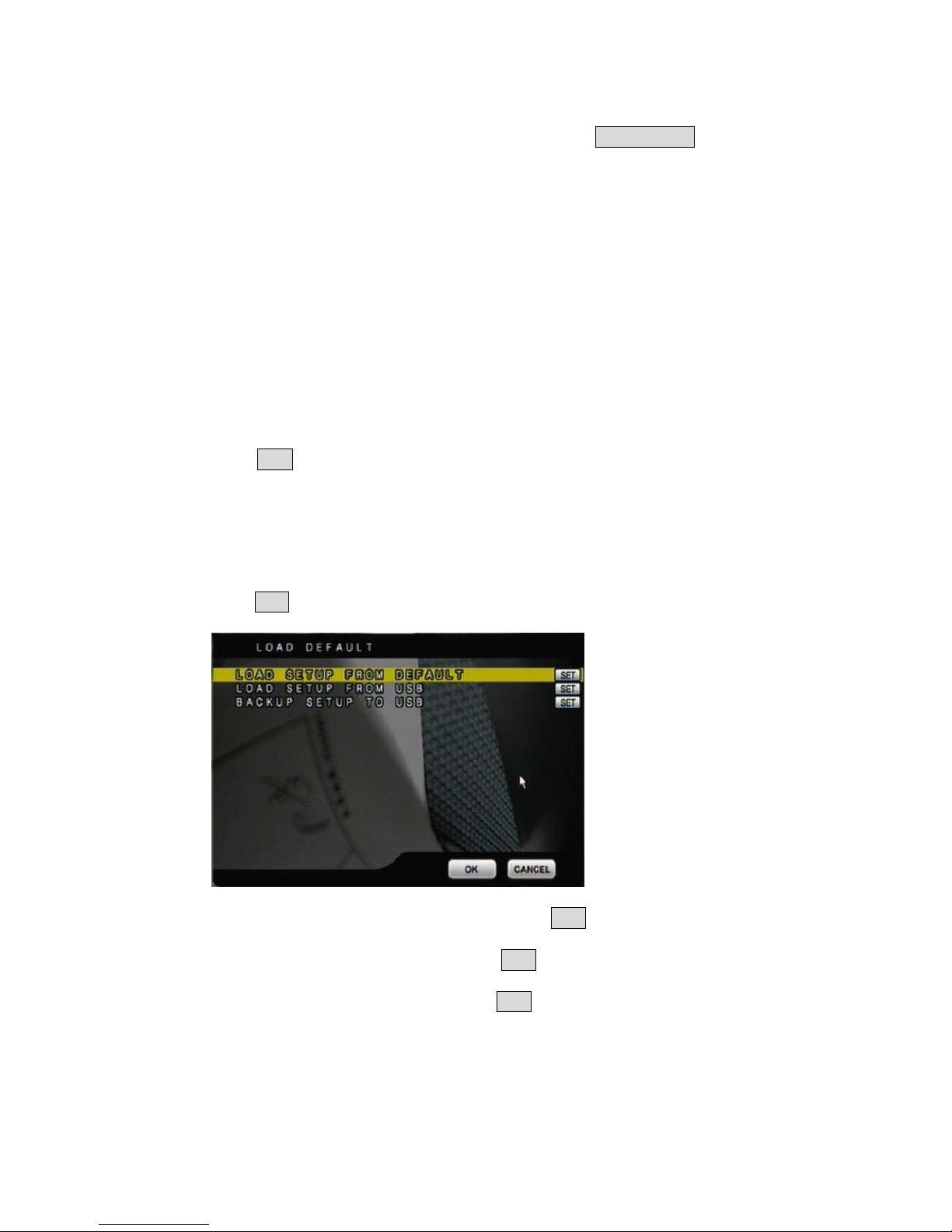
I. LOAD DEFAULT
Press SET button to entry CONFIGURE SET screen. There are LOAD SETUP FROM
DEFAULT, LOAD SETUP FROM USB and BACKUP SETUP TO USB three parts.
I-1. LOAD SETUP FROM DEFAULT: Press SET button to load the setting back to
factory default.
I-2. LOAD SETUP FROM USB: Press SET button to load the pen drive setting to
the current DVR.
I-3. BACKUP SETUP TO USB: Press SET button to backup the current DVR setting
into pen drive.
Page 32
32
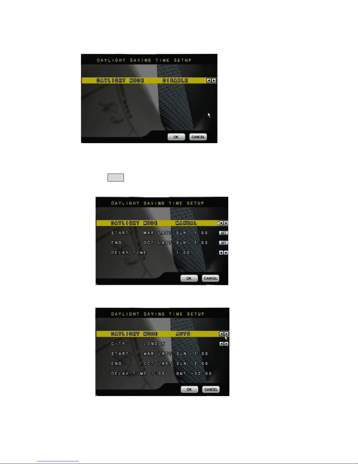
J. DAYLIGHT SAVING TIME SETUP
Press ◄ or ►/ mouse wheel to change the DAYLIGHT MODE option: Disable,
Manual and Auto.
J-1. MANUAL MODE
Use SET to change the Day Light Saving start and end time.
Press ◄ or ►/ mouse wheel to change DELAY TIME
J-2. AUTO MODE
Press ◄ or ►/ mouse wheel to change CITY option. Different CITY will have
different START, END and DELAY TIME.
Page 33
33
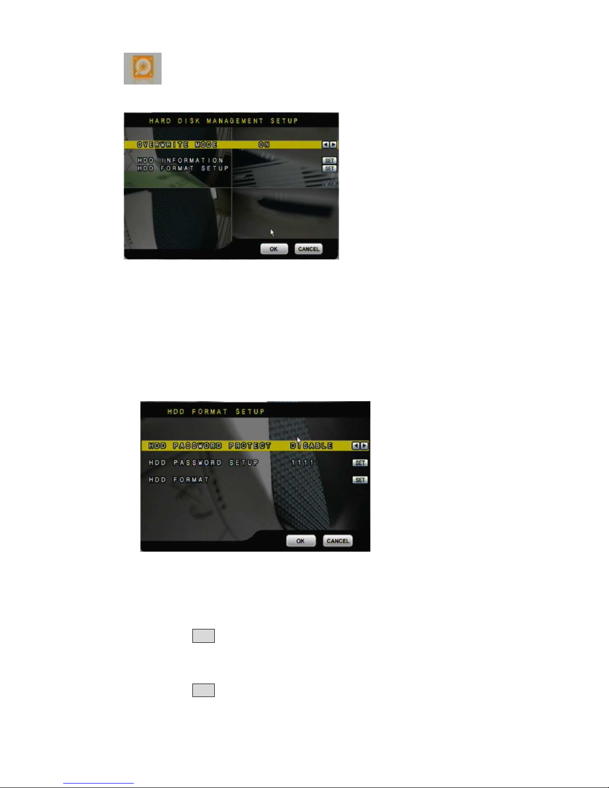
3.9 HARD DISK SETUP
A. OVERWRITE MODE
Press ◄ or ► to change value OVERWRITE MODE ON or OFF.
B. CAPACITY WARNING (When Overwrite Mode is OFF, Capacity Warning will
enable)
Press ◄ or ► to change value to 20/ 15/ 10 or 5% with non-overwrite mode. When
LEFT RATIO is below the setting, it will enable AUDIBLE ALARM (If AUDIBLE
ALARM of BUZZER of ALARM SETUP is ON).
C. HDD INFORMATION
Press SET to display HDD information.
D. HDD FORMAT SETUP
D-1. HDD PASSWORD PROTECT
Press ◄ or ►/ mouse wheel to change value for hard disk format password
protection.
D-2. HDD PASSWORD
Press SET then use mouse to change password.
Default password: 1111
D-3. HDD FORMAT
Press SET to get into FORMAT setup.
Press YES or NO to execute.
Page 34
34
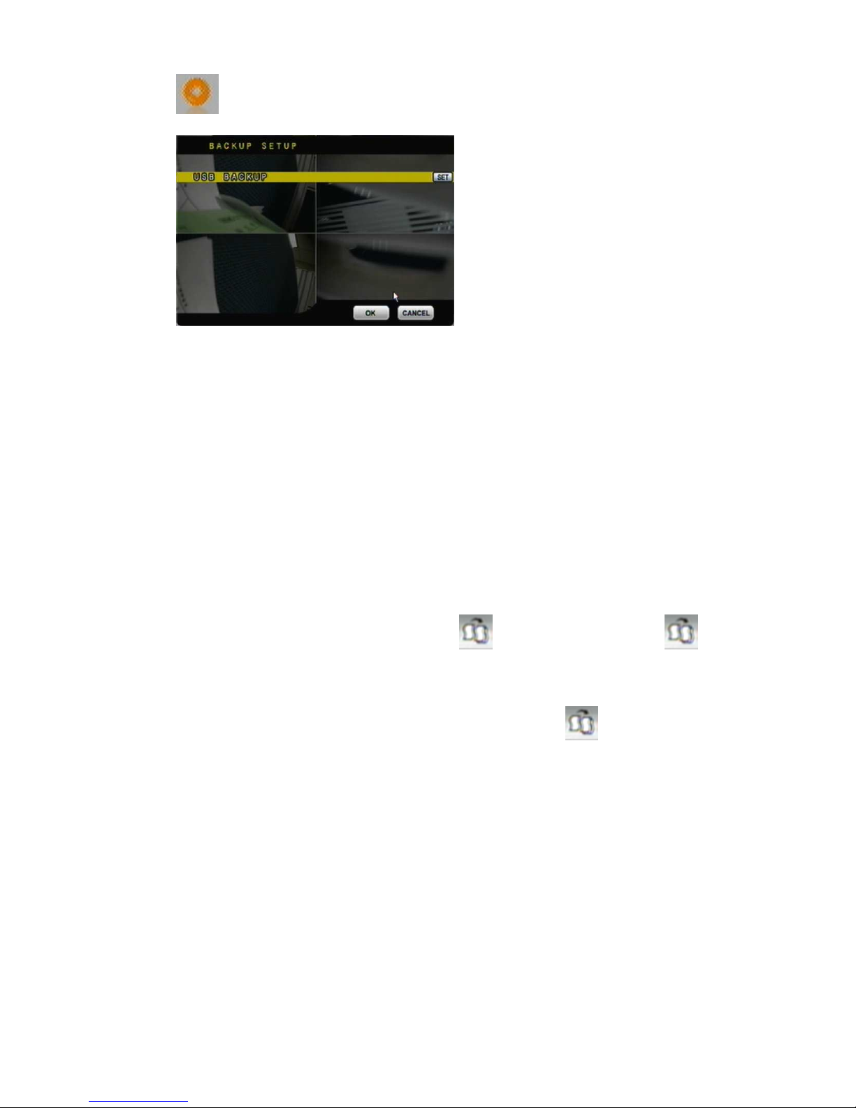
3.10 BACKUP SETUP
NOTE: *For function stability, Ethernet remote control function (IE) will be
stopped when processing backup function.
*USB DEVICE BACKUP : 3.2MB/ per sec.
A. USB BACKUP
Due to each USB device with different USB driver ICs, their compatibilities differ, too.
This system is compatible with most of USB flash memory. If there is compatible
issue, please refer to APPENDIX B. In addition, please format USB flash memory
with FAT32.
BEFORE BACKUP
A. In live viewing mode, insert USB device into a USB port of the DVR.
B. Get into playback mode by PLAY TIME SEARCH or EVENT LIST SEARCH and
play back videos that are going to be as backup.
VIDEO BACKUP
In multiplexer or full screen mode, press to start backup and press to end
backup. The system will backup automatically.
PICTURE BACKUP
In multiplexer or full screen mode, press ► and press . The system will start
backup picture by picture.
Press ▲ or ▼ to select items.
Press ◄ or ► to change values.
Press SET to see more options.
Page 35
35
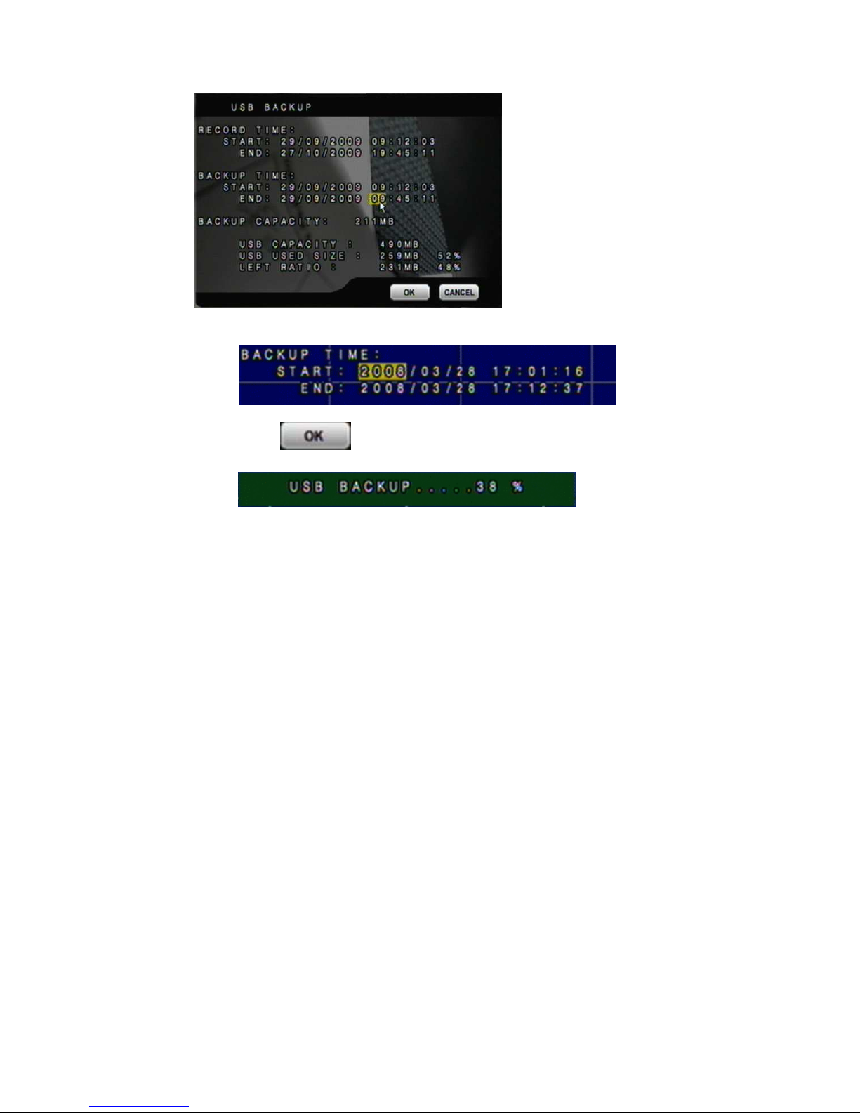
USB BACKUP MENU
User can use the mouse wheel to change the backup Start/ End time。
Click to start backup, the total process will be shown on screen.
BACKUP FILE NAME
Each backup file will be named as START TIME.
EXAMPLE: 174624.264 is 17:46:24
AFTER BACKUP
After backup, the system will copy “R6VIEWER.EXE” automatically on USB device
for the user to play back backup file.
Page 36
36
4 DVR PLAYBACK
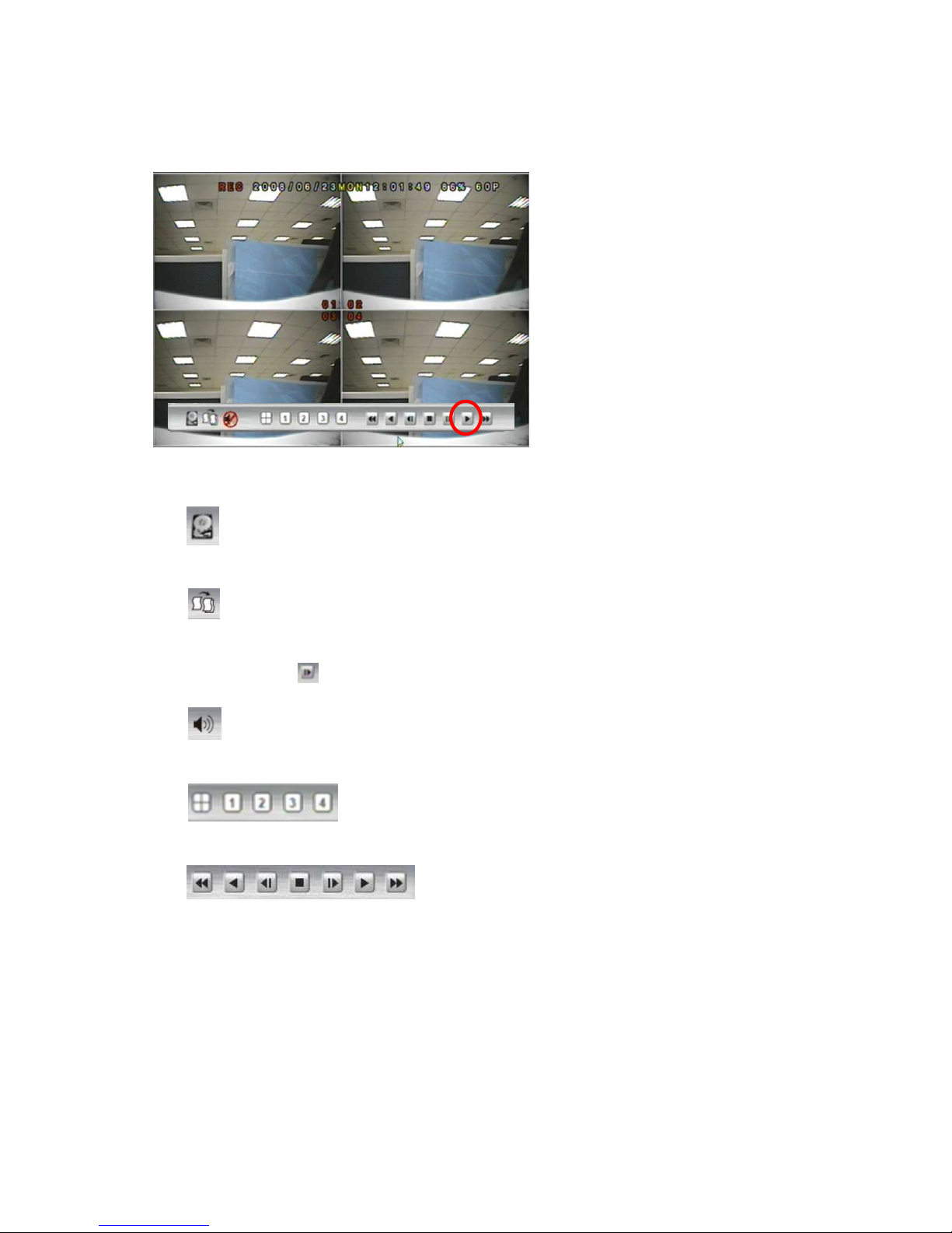
Click the playback button on the pop-up
menu.
Note: the pop-up menu can be activated
by moving the mouse cruise to the
bottom of the live viewing screen.
A. DISK INFORMATION
With playback mode, press this button to display disk and pen drive information.
B. RECORD BACKUP
With playback mode, press this button to backup record (.264 video backup) and press this
button again to finish backup. For performing the single image backup (.Y42 single image
backup), press first and then click this button to backup the necessary image.
C. AUDIO CONTROL
Press this button to turn the audio on or off
D. DISPLAY CONTROL
Within playback mode, use display control to switch the camera channel.
E. RECORD AND PLAYBACK CONTROL
Same as front panel controller and remote controller.
Page 37
37
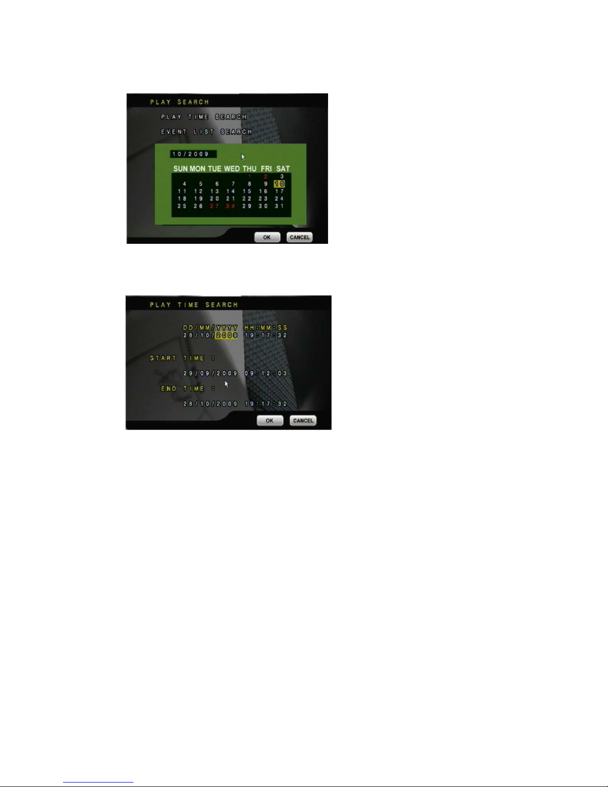
4.1 TIME SEARCH
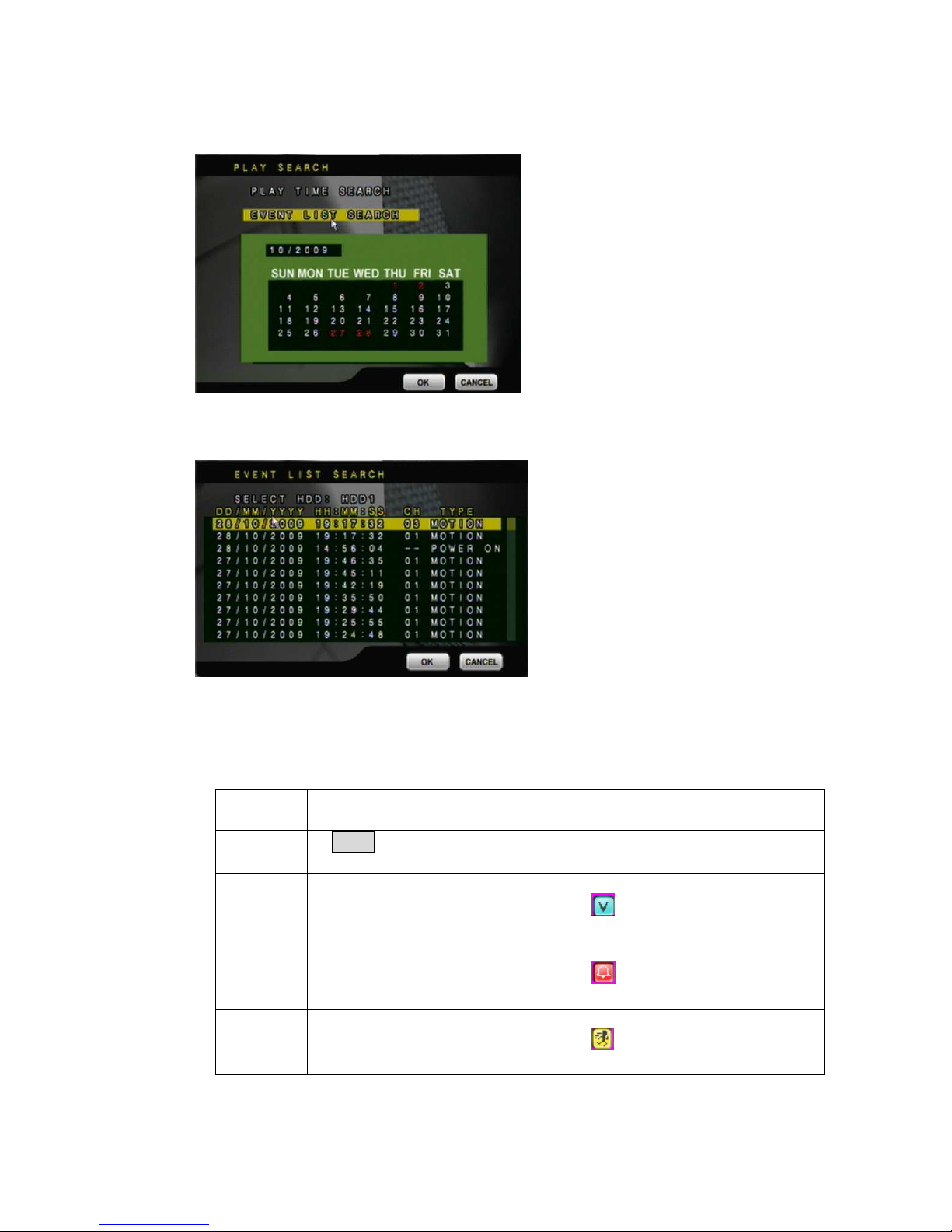
Double click Left button of mouse to trigger play time search.
Please set the start and end time to search.
Page 38
38
4.2 EVENT SEARCH
Double click Left button of mouse to trigger event search.
Please select the event to playback.
NOTE: Display the type of the event as follows.
POWER If the DVR got power loss, it will record the date and time of
rebooting.
RECORD
If REC. button has been pressed, it will record the date and time in the
event list.
V.LOSS When a camera signal is lost, it will record the date, time, and
corresponding channel. Moreover, the icon will display on the
corresponding channel.
ALARM When ALARM is triggered, it will record the date, time, and
corresponding channel. Moreover, the icon will display on the
corresponding channel.
MOTION When MOTION is detected, it will record the date, time, and
corresponding channel. Moreover, the icon will display on the
corresponding channel.
Page 39
39
5 BACKUP PLAYBACK
SYSTEM REQUIREMENT
CPU: Intel Celeron 1.6G
MEMORY: 256MB.
VGA: 32MB
VGA RESOLUTION: 1024 x 768.
OS: Windows XP / 2000
SUGGESTED REQUIREMENT
CPU:Intel P4 2.8G
MEMORY:512MB or above
VGA:64MB or above
VGA RESOLUTION:1024 x 768
OS: Windows XP / 2000
5.1 MAIN SCREEN SETTING
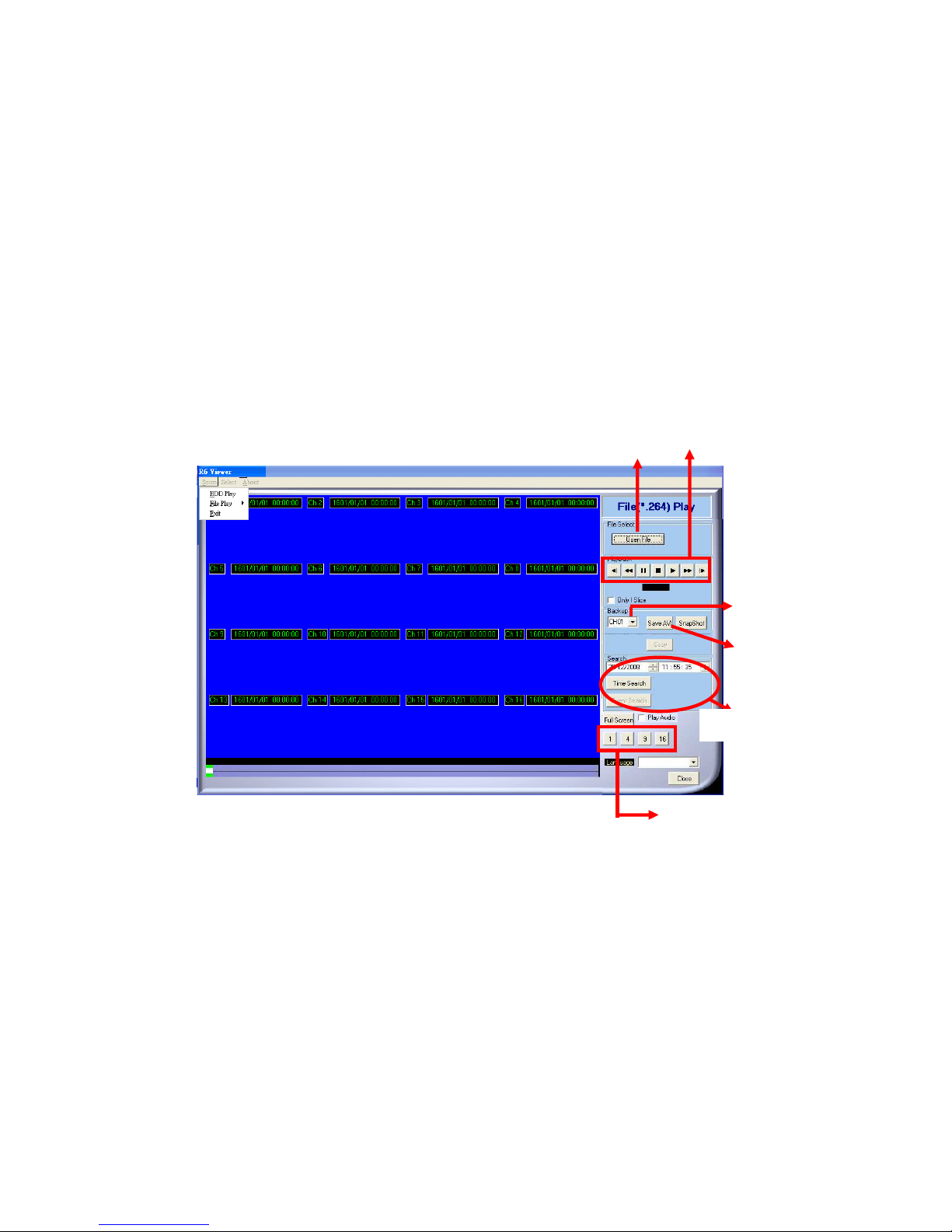
A. MAIN SCREEN
Single, 4, 9, 16 Split Screen
Time & Event Search
Save as AVI
Control Panel
Open File
Channel Selected
Page 40
40
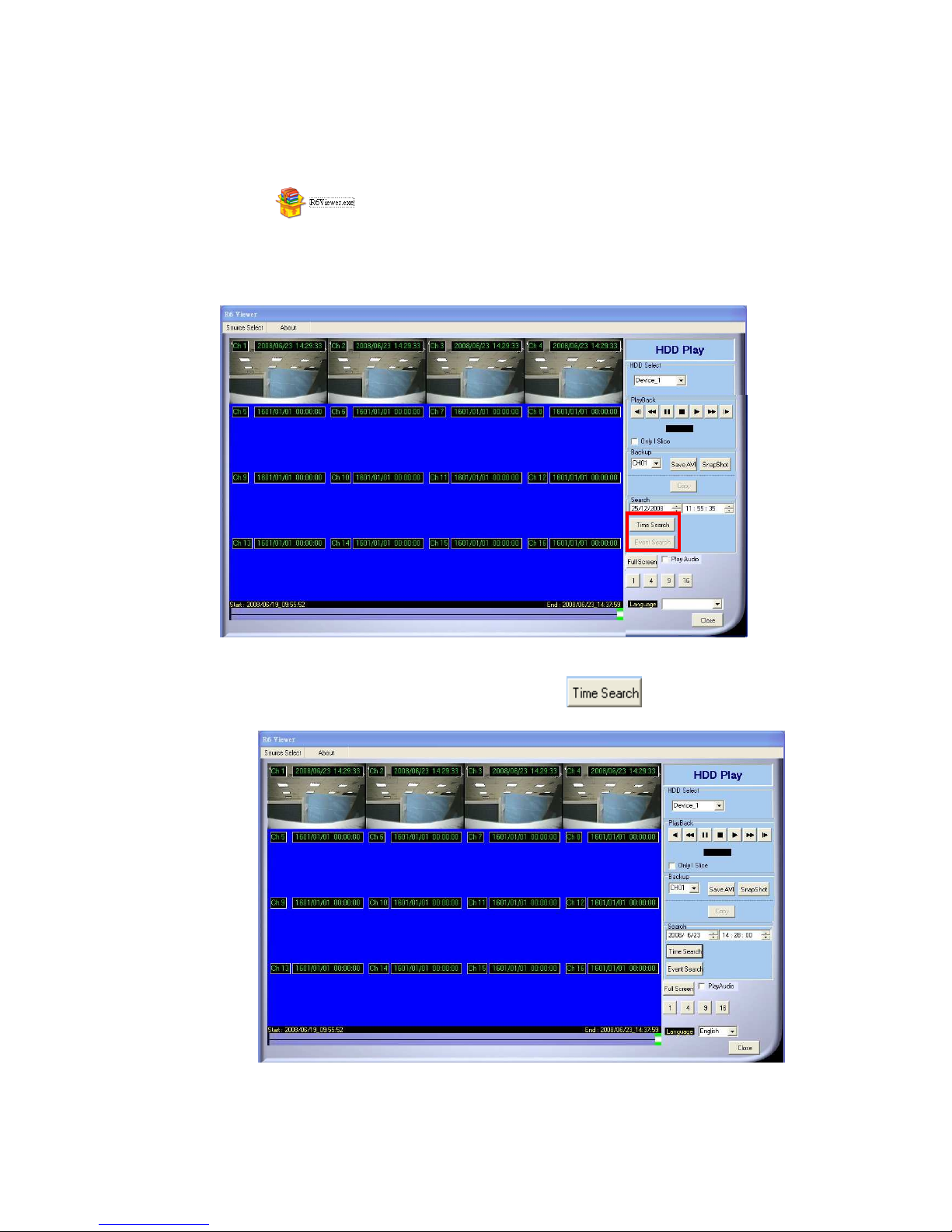
B. HDD PLAY
Play about all the data from the Hard disk of DVR or perform the specific Time and
Event Search to play.
Note: Remove the DVR HDD and connect to the PC first. Then, use DVR
player (R6Viewer.exe) to play the data of HDD. DVR player
(R6Viewer.exe) can be attained from the attached CD or via the Internet;
moreover, while performing USB backup and DVD-RW backup, the software
will be built automatically as well.
B-1. TIME SEARCH
Insert search Date and Time and then click to play all the searched
film.
Page 41
41
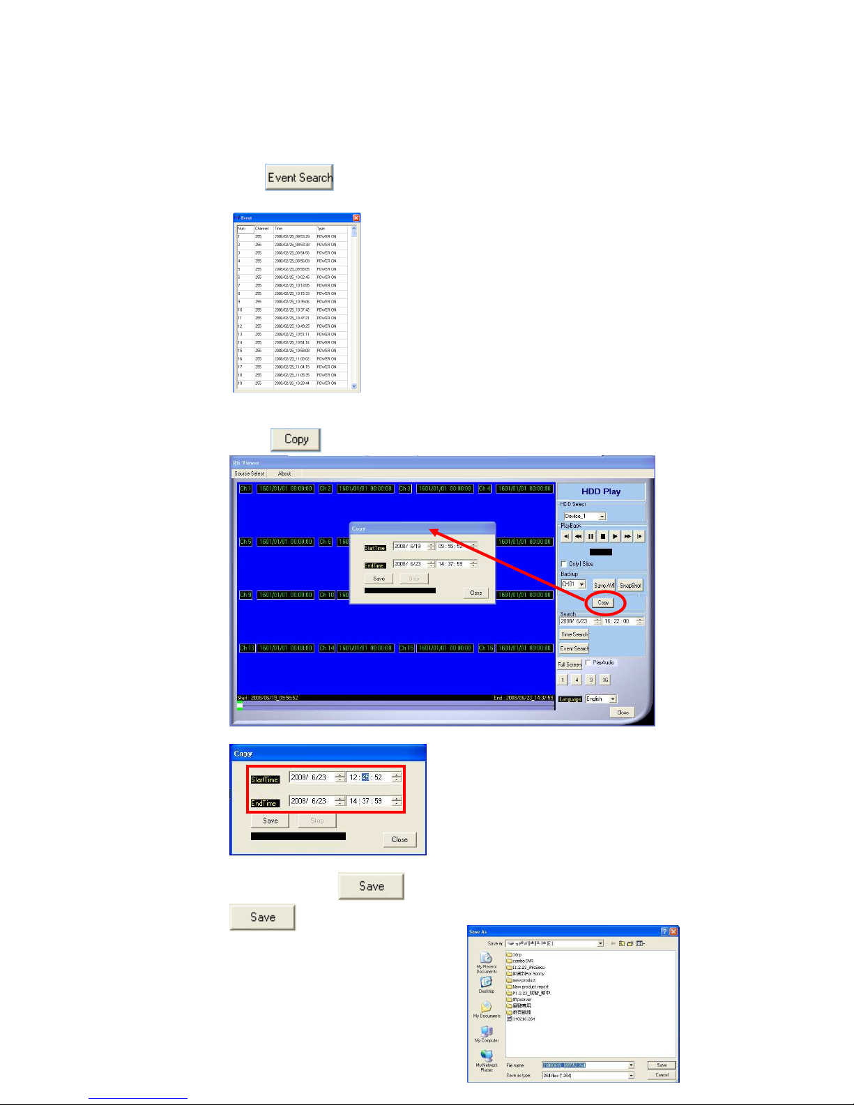
B-2. EVENT SEARCH
It will display all the events which are reserved within the DVR HDD after
press (Shown in the following) and double click left button of mouse
to trigger event.
B-3. HDD COPY
Copied and reserved the DVR HDD data to other data storage device.
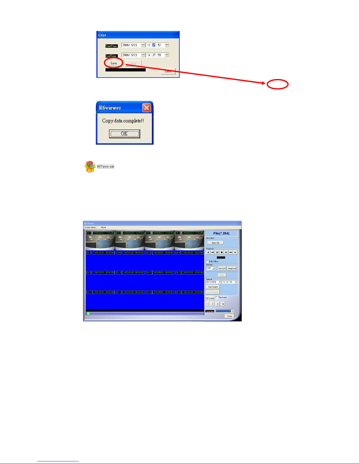
Press button, the Copy screen will pop-up.
Then, select the “StartTime” and “EndTime”.
After that, press button to choose the storage destination and press
to start reserving.
Page 42
42
Finally, the complete information will pop-up while finished storage.
(R6 Viewer.exe) can play not only DVR H.D.D. but also the *.264
and *.Y42 files which are reserved within the data storage devices. (i.e. CD/DVD
disc, pen drive and the PC H.D.D which the data backup from DVR H.D.D)
C. File (*.264) Play
D. File (*.Y42) Play
Page 43

43
Page 44
44
5.2 CD/DVD BACKUP PLAYBACK
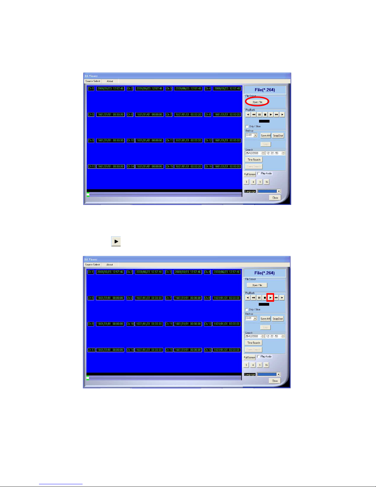
A. Insert the CD/DVD disk into CD/DVD ROM, the software will auto pop out, and select
"Open File" and pick up the file.
B. Press the icon to play the video.
Page 45
45
5.3 USB & LOCAL BACKUP FILE PLAYBACK
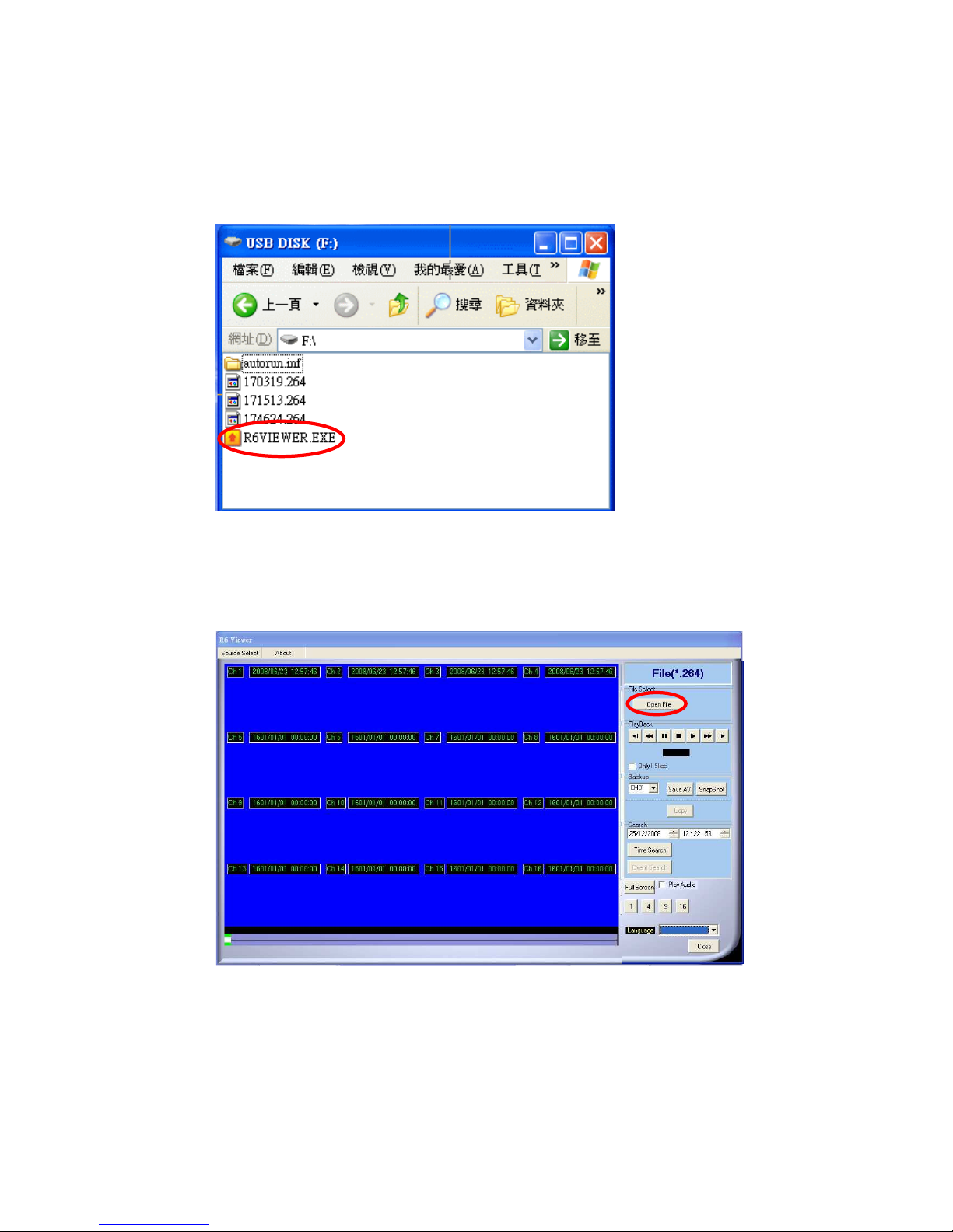
A. Plug the USB disk into PC or check the local backup folder.
If using USB mode, please double click the player.exe from the pop-up diagram. (As
below)
B. The play backup program would appear on the screen, select "Open File".
Page 46
46
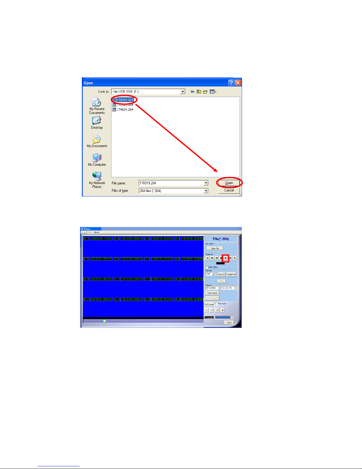
C. Open the USB disk located driver letter. (Example E:) or the local backup folder, and
pick the file to playback.
The backup file will named as the time when backup, as like:
170319.264 will be 17:03:19
D. Press the play icon to play the video or still picture.
Page 47
47
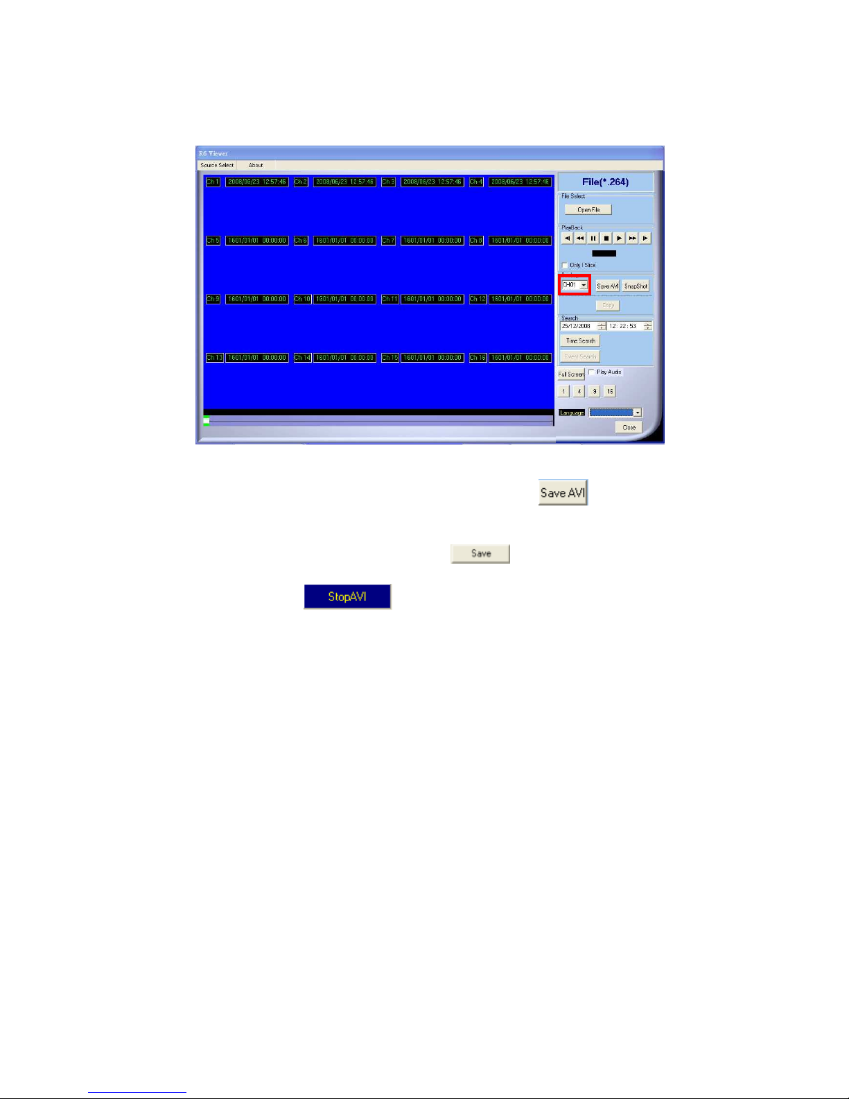
5.4 BACKUP FILE TO AVI
A. Please select specific channel to backup.
B. During video playback mode please press AVI bottom to start.
C. Make up a filename and path than press bottom to start AVI backup.
D. Press AVI bottom to finish backup.
Page 48
48
6 NETWORK VIEWING & PLAYBACK
SYSTEM REQUIREMENT
CPU: Intel Celeron 1.6G
MEMORY: 256MB.
VGA: 32MB
VGA RESOLUTION: 1024 x 768.
OS: Windows XP / 2000
SUGGESTED REQUIREMENT
CPU:Intel P4 2.8G
MEMORY:512MB or above
VGA:64MB or above
VGA RESOLUTION:1024 x 768
OS: Windows XP / 2000
6.1 IP ADDRESS SETUP ON PC SITE
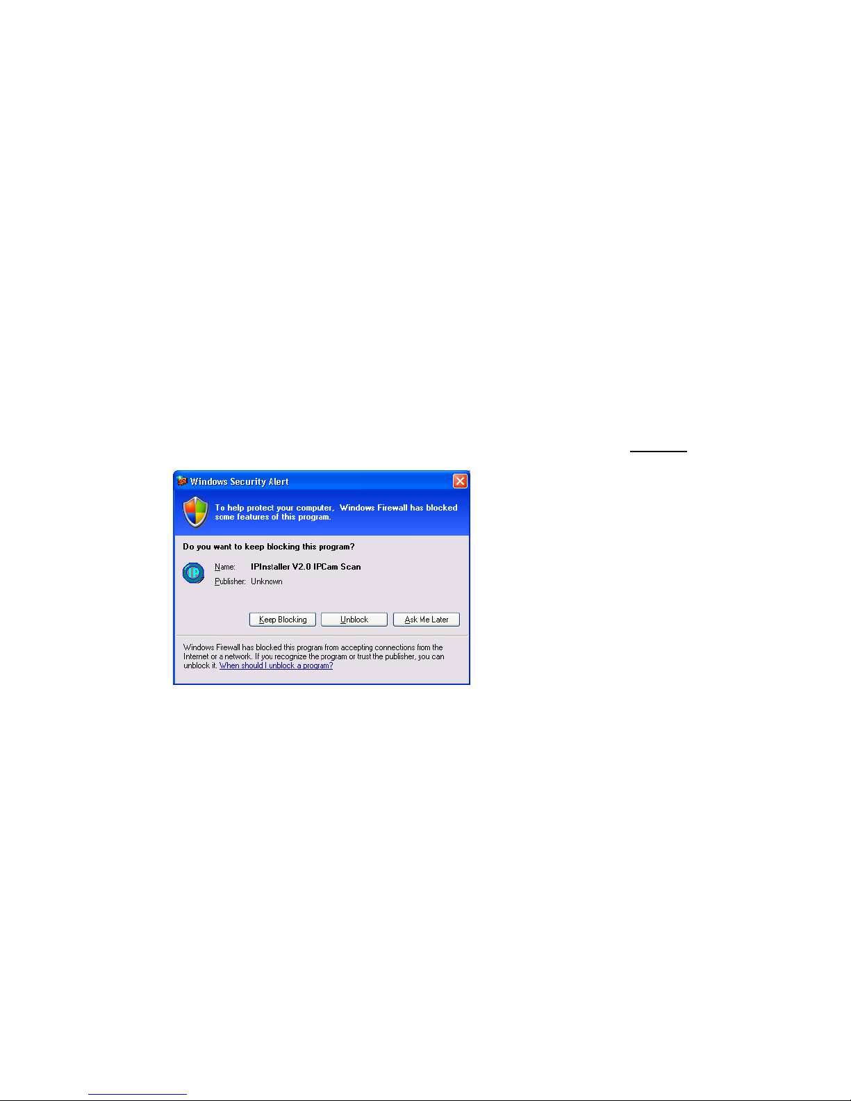
Install cameras inside in LAN or use network cable to connect with PC. This is for
IPInstallerEng.exe to set up IP address of cameras. If OS is Windows XP SP2 or above,
the following Windows Security Alert will popup. Then, please click on Unblock.
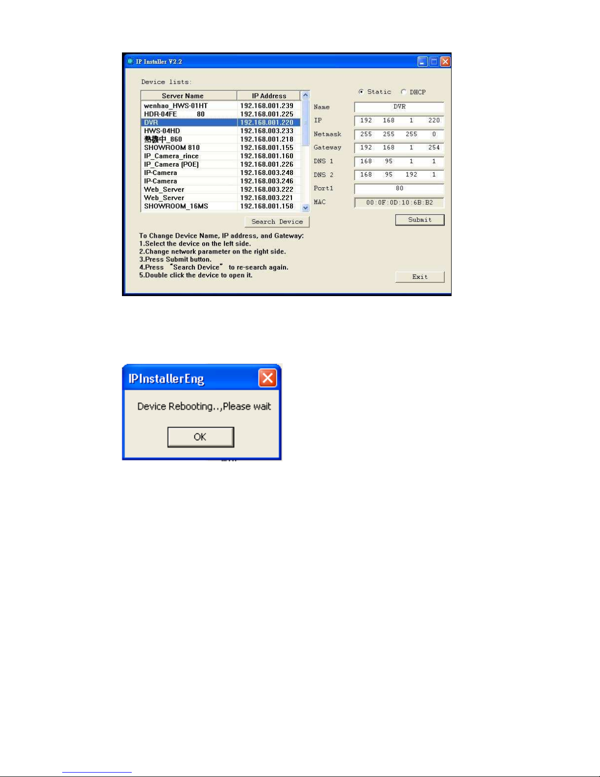
Then, IPInstallerEng.exe will popup:
DVR default IP address is 192.168.1.220
Page 49
49
NOTE: Please input correct network parameters without blank spaces.
On Device Lists, it lists all servers. Click on one server and then its IP setting will show
on the right side. After editing the parameters and clicking on Submit, the following
dialogue box will popup. And, it will reboot the device with new parameters.
6.2 OPTIONAL MICROSOFT INTERNET EXPLORER SETUP
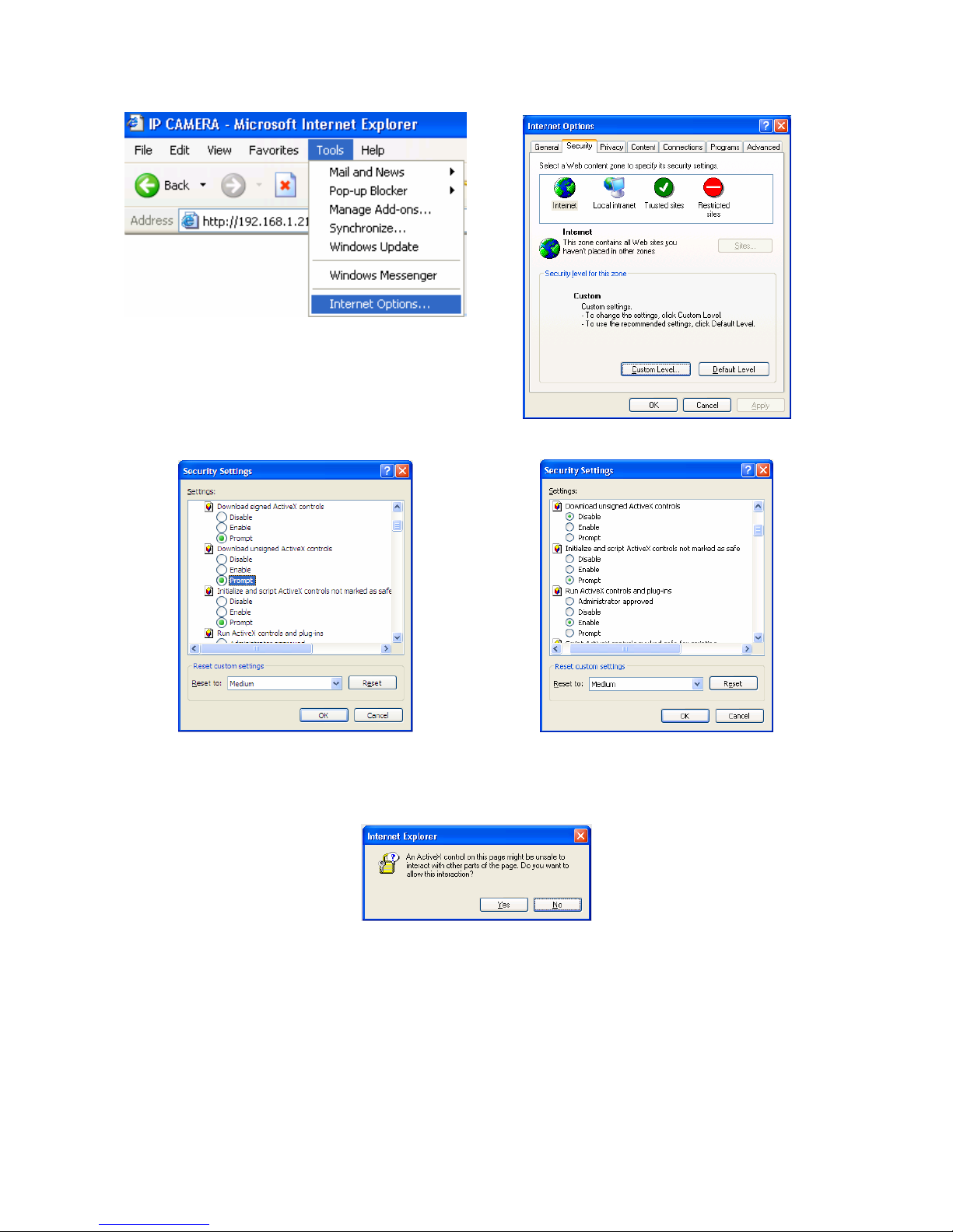
OPTION 1: DISABLE ACTIVEX WARNING
A. IE Tools Internet Options Security Custom Level Security Settings
Download unsigned ActiveX controls Enable or Prompt (recommend).
B. IE Tools Internet Options Security Custom Level Security Settings
Initialize and script ActiveX controls not marked as safe Enable or Prompt
(recommend).
Page 50
50
1 2
3 4
5
Above three options are all based on select as the prompt.
As indicated in the dialogue box. Please select "YES."
Page 51
51
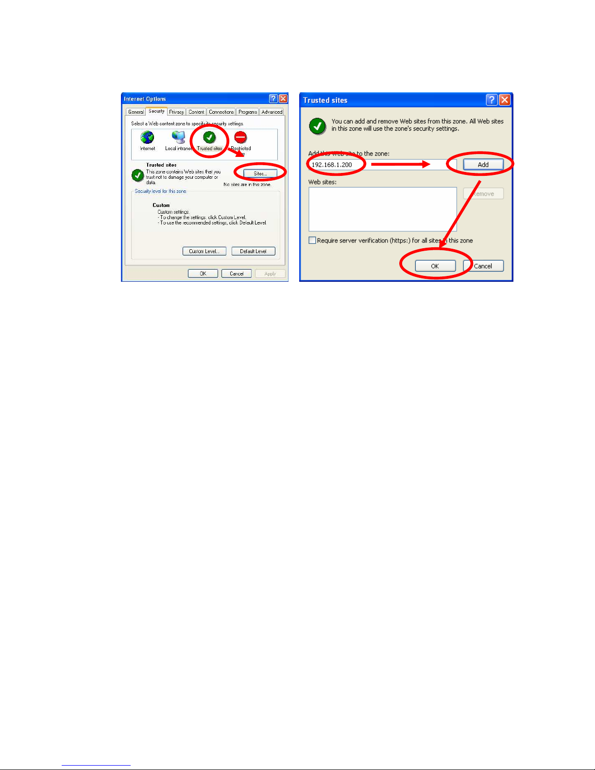
OPTION 2: ADD TO TRUSTED SITES
IE Tools Internet Options Security Trusted sites Sites
Page 52
52
6.3 LOGIN
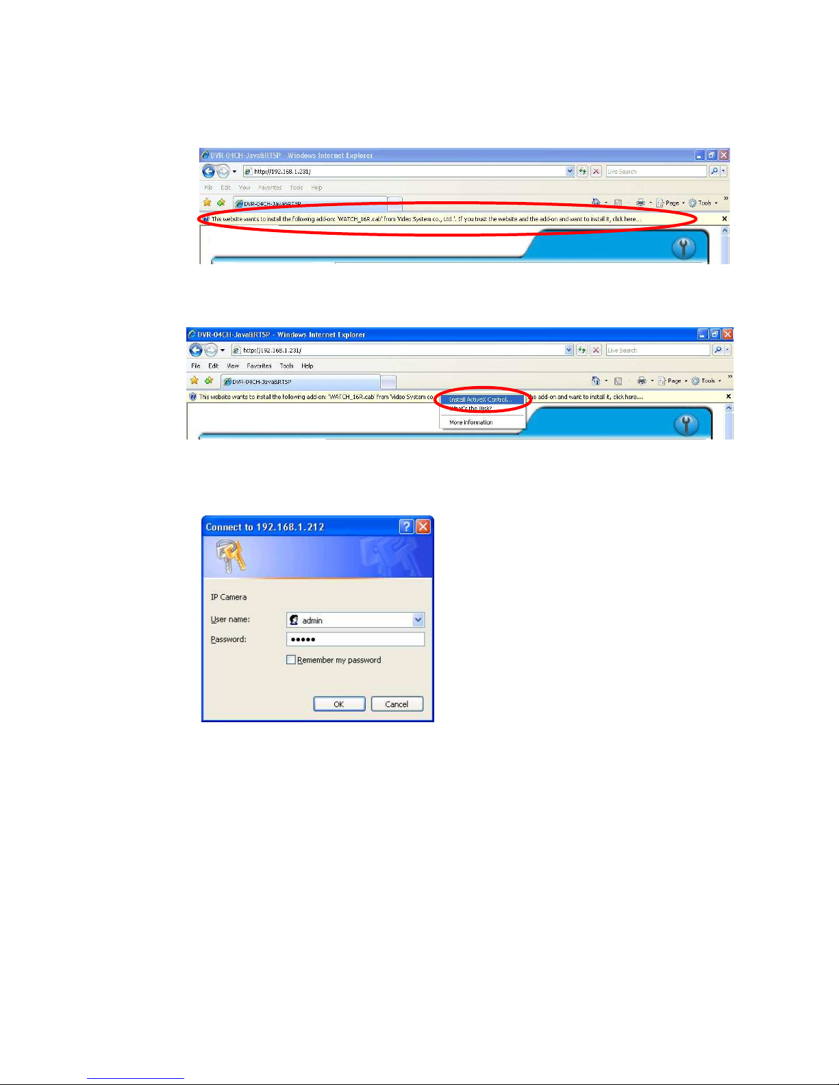
A. INSTALL ACTIVEX
B. START INSTALL ACTIVEX
C. ACCOUNT & PASSWORD LOGIN
After IP setup and connect to network or LAN, type IP address on IE Browser
directly. The following User name & Password Login window will popup.
Default user name: admin
Default password: admin
Page 53
53
6.4 REMOTE CONTROL
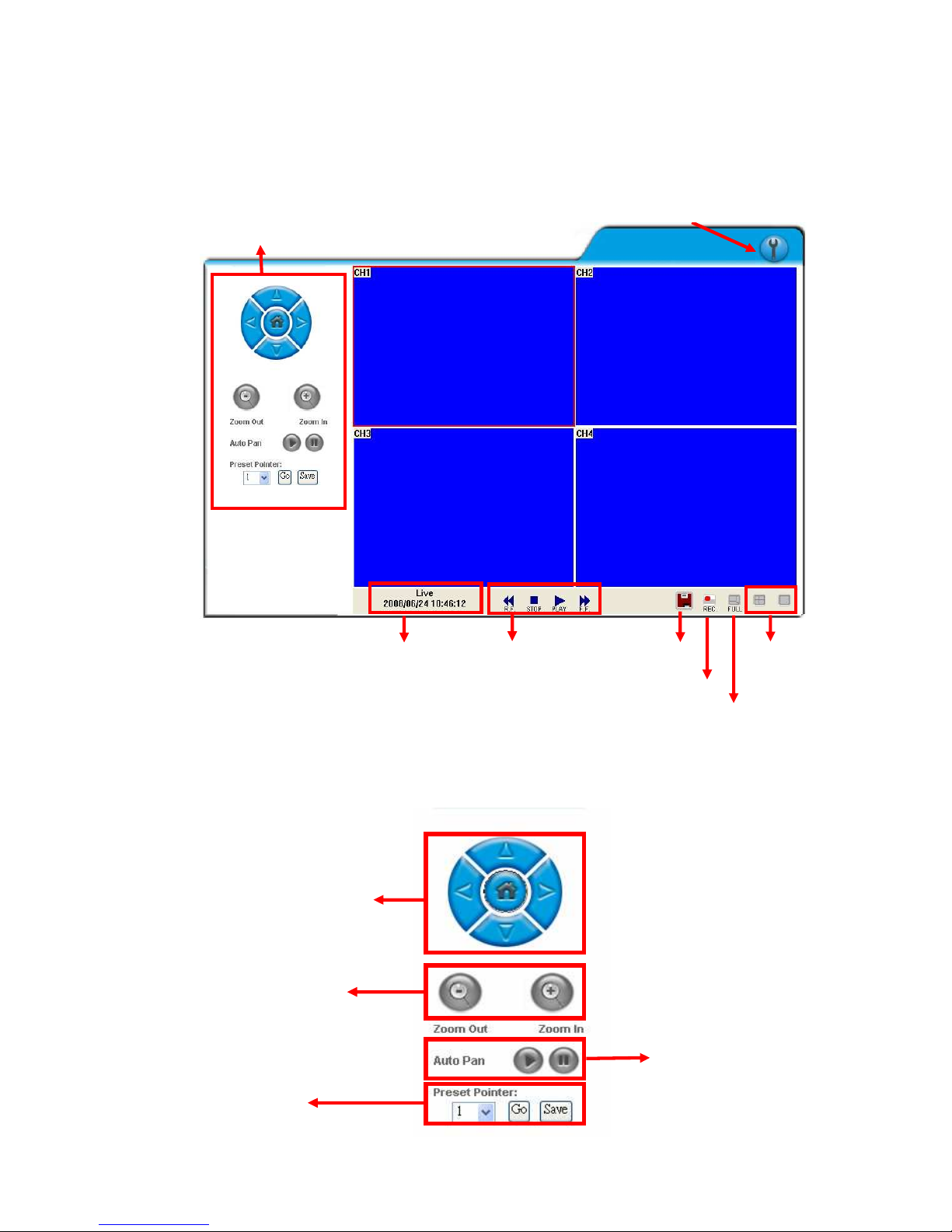
LIVE VIEWING
A. DVR Configuration
Get into DVR network menu.
B. PTZ Control
PTZ control function panel
Direction Keys
PTZ Zoom in/out
Preset Point
Setup
Auto Pan Function
PTZ Control
System Time
Playback
Time-Point
Backup
REC
Full Screen
Screen
Format
DVR Configuration
Page 54
54
C. SYSTEM TIME
Live viewing mode: The current live viewing time.
D. SCREEN FORMAT
Switch screen format and click twice to switch different channels with full screen.
E. Full Screen. Click again to return.
F. REC. Videos are saved as AVI file.
G. Playback
H. Time-Point Backup
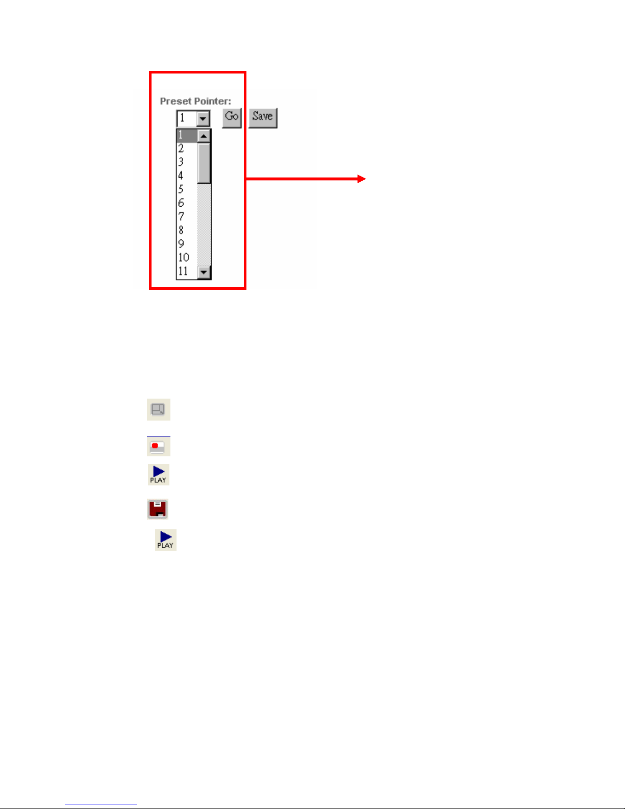
Click , and playback window will popup
Up to 32 preset points
for operation
Page 55
55
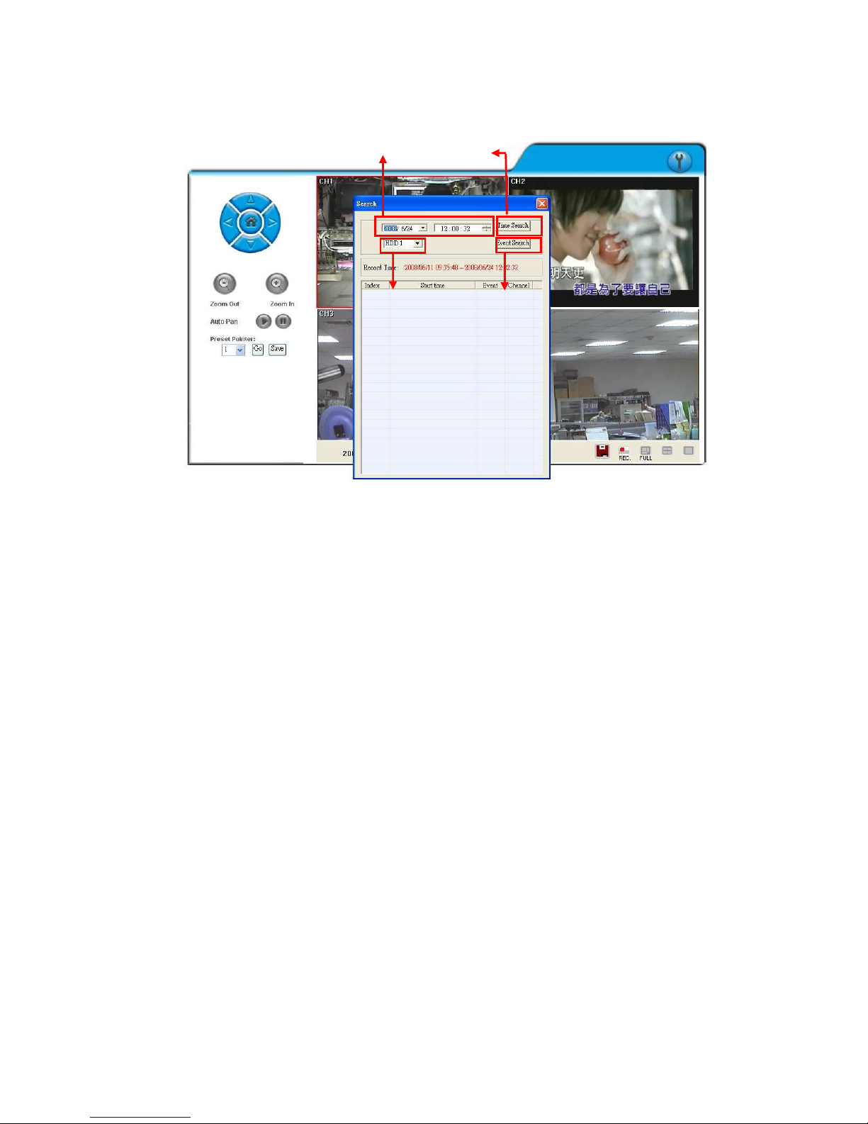
PLAYBACK by TIME SEARCH & EVENT SEARCH
A. HDD Select
User can select HDD1 or HDD2 for playback
B. Playback Time
User can select the time then press “Time Search” for playback.
C. Time Search
User can select the time then press “Time Search” for playback.
D. Event Search
User can select event item by pressing “Event Search” for playback.
Playback Time
Playback Time
HDD Select
Event Search
Time Search
Page 56
56
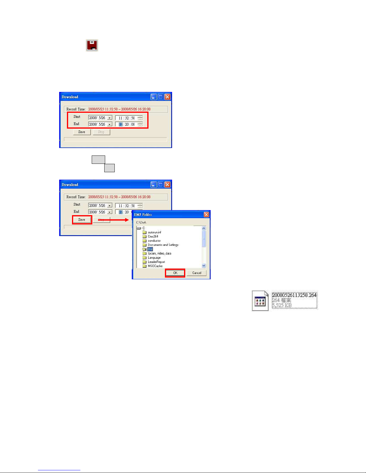
Click to operate Time-Point backup.
TIME-POINT BACKUP
First, select Start and End backup time which have to among the Record Time.
Then, click Save button to select the position on PC where the user is going to backup the data.
After that, press OK button to start the backup.
Finally, double-click the left button of the mouse to open the saved backup file. The backup file
will named as the time when start to backup, such as,
(20080526113258.264) will be 2008/05/26 11:32:58.
Page 57
57
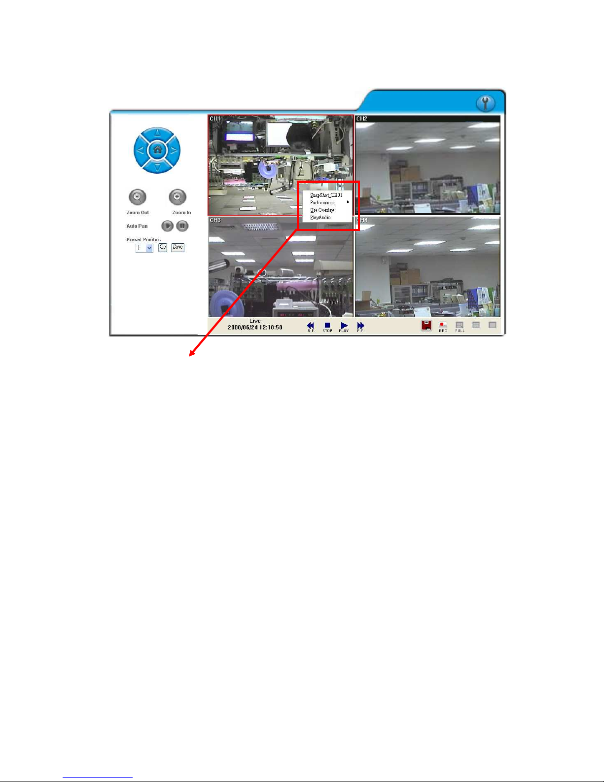
OTHER FUNCTIONS
User can use other functions by clicking the left of mouse
A. Snapshot:
User can save any single picture from image.
B. Performance:
User can select image quality (high, medium & low).
C. Use Overlay:
User can use Overlay function.
D. Play audio:
User can play audio function by channel.
Note: remote user can receive audio from DVR & the audio will be saved with image
when processing video backup.
Page 58
58
6.5 CONFIGURE
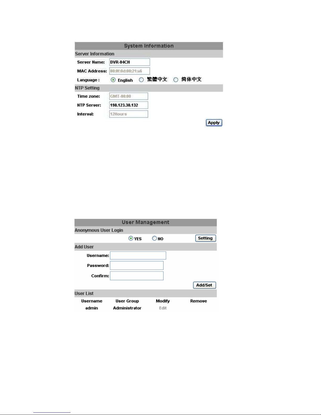
A. System - System Information
A-1 SYSTEM INFORMATION
SERVER NAME: This name will show on the IP Installer.
LANUGAGE::::There are English, Traditional Chinese, and Simplified
Chinese.
A-2 NTP Setting
NTP SERVER: Revise the time of DVR via different NTP Server.
Note: Time zone and Interval cannot adjust in here (User can adjust both in
DATE and TIME SETUP option of DVR Menu).
B. SYSTEM – USER MANAGEMENT
User Management provides 3 levels of limits of authority: Administrator (the
highest), User, and Guest.
Administrator: Possessing the highest level of authority to operate full functions
within network.
User: Having Live Image and Video Playback authority. Moreover, PTZ controlled
is included as well.
Guest: Only have Live Image authority.
Page 59
59
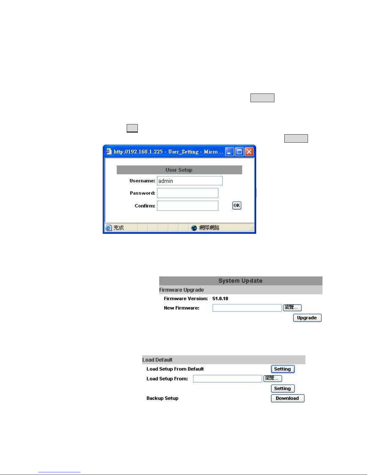
Default administrator account: Username: admin Password: admin
B-1. ANONYMOUS USER LOGIN:
YES: Accept anonymous user login without password as guest login.
NO: Anonymous login unacceptable.
B-2. USER MANAGEMENT:
Add: Input Username and Password and then click on Add/Set to save.
Modify: Click on selected User name on User List and the following window
will popup. After inputting Password and Confirm Password, click on
OK.
Remove: Click on selected User name on the user list and click on Remove.
C. SYSTEM / SYSTEM UPDATE
C-1. Firmware Upgrade: Click on the “Browse” button to select the latest firmware
and then press “Upgrade” button to upgrade the firmware.
C-2. Load Default: There are three kinds of Settings. One is Load Setup From
Default, another is Load Setup From and the other is Backup
Setup.
Load Setup From Default: Press “Setting” button to load factory default.
Load Setup From: Click on “Browse…” button to select DVR setting file and
then press “Setting” button to upload the setting file to DVR.
Page 60
60
Backup Setup: Click on “Download” button to download the DVR setting file
into the specific storage device.
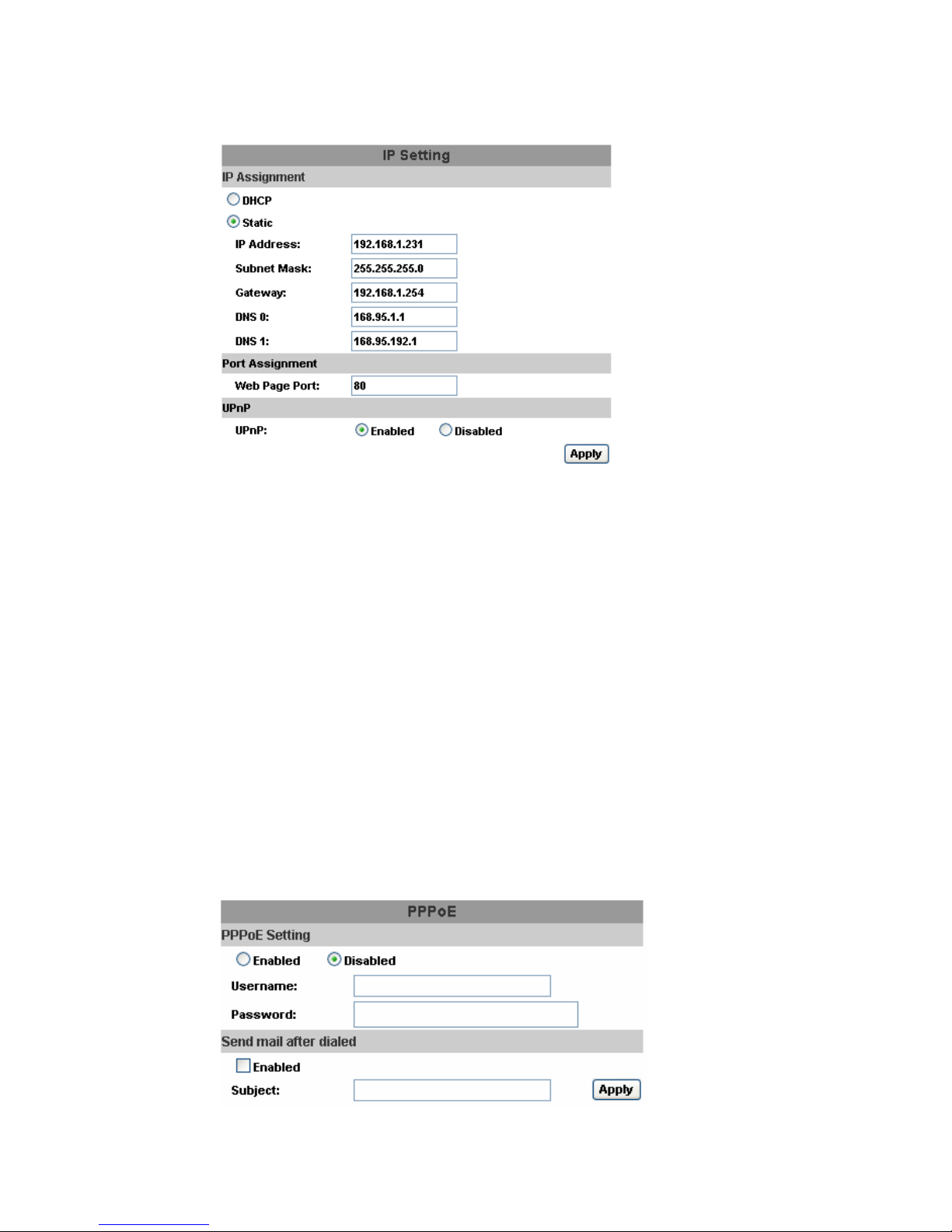
D. NETWORK – IP SETTING
D-1. IP ASSIGNMENT
DHCP: In Dynamic Host Configuration Protocol (DHCP) mode, DHCP
server will get setting done automatically.
STATIC IP: Please input IP address, Subnet Mask, and Gateway based on
network environment.
D-2. PORT ASSIGNEMENT
With IP Share (Router), the following Ports needed to be adjusted in case of
conflict.
D-3. UPnP
If UPnP service is enabled on your computer, the DVR will automatically be
detected and a new icon will be added to “My Network Places”. However, if
UPnP service is disabled, the DVR will not be detected automatically.
Note: UPnP must be enabled on your computer.
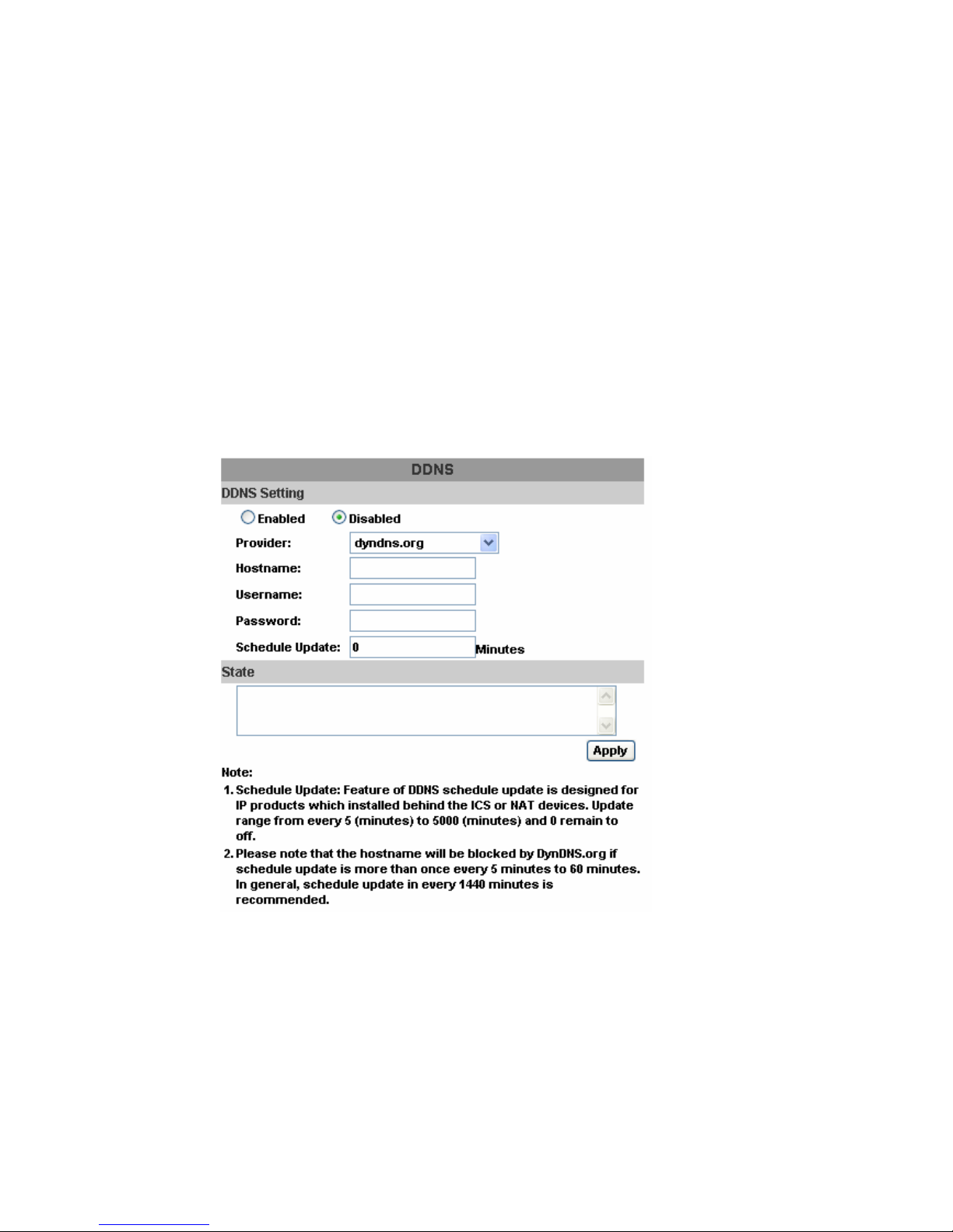
E. NETWORK – PPPoE
Page 61
61
E-1. PPPoE SETTING
Click on Enabled to enable ADSL dial function.
Username: Username for ADSL account.
Password: Password for ADSL account.
After dialed successfully, new IP address will appear.
E-2. SEND MAIL AFTER DIALED
Click on Enabled to enable SEND MAIL AFTER DIALED function.
E-3. SUBJECT
Mail subject.
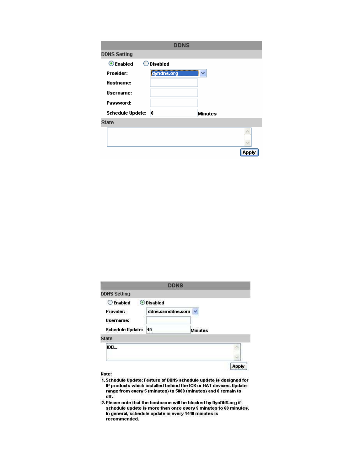
F. NETWORK / DDNS SETTING
Click on Enabled to enable DDNS function.
Page 62
62
F-1. DYNDNS.ORG
DDNS SETTING - DYNDNS.ORG
PROVIDER: Select dyndns.org
HOSTNAME: The registered hostname in DYNDNS.ORG.
USERNAME: The registered username in DYNDNS.ORG.
PASSWORD: The registered password in DYNDNS.ORG.
SCHEDULE UPDATE: A period of time to update IP address.
STATE
1. Updating: Information update.
2. Idle: Stop service.
3. DDNS registered successfully, now log by
http://<username>.ddns.camddns.com: Registered successfully.
4. Updating Failed, the name is already registered.
5. Updating Failed, please check your internet connection.
F-2. DDNS.CAMNNDS.COM
Page 63
63
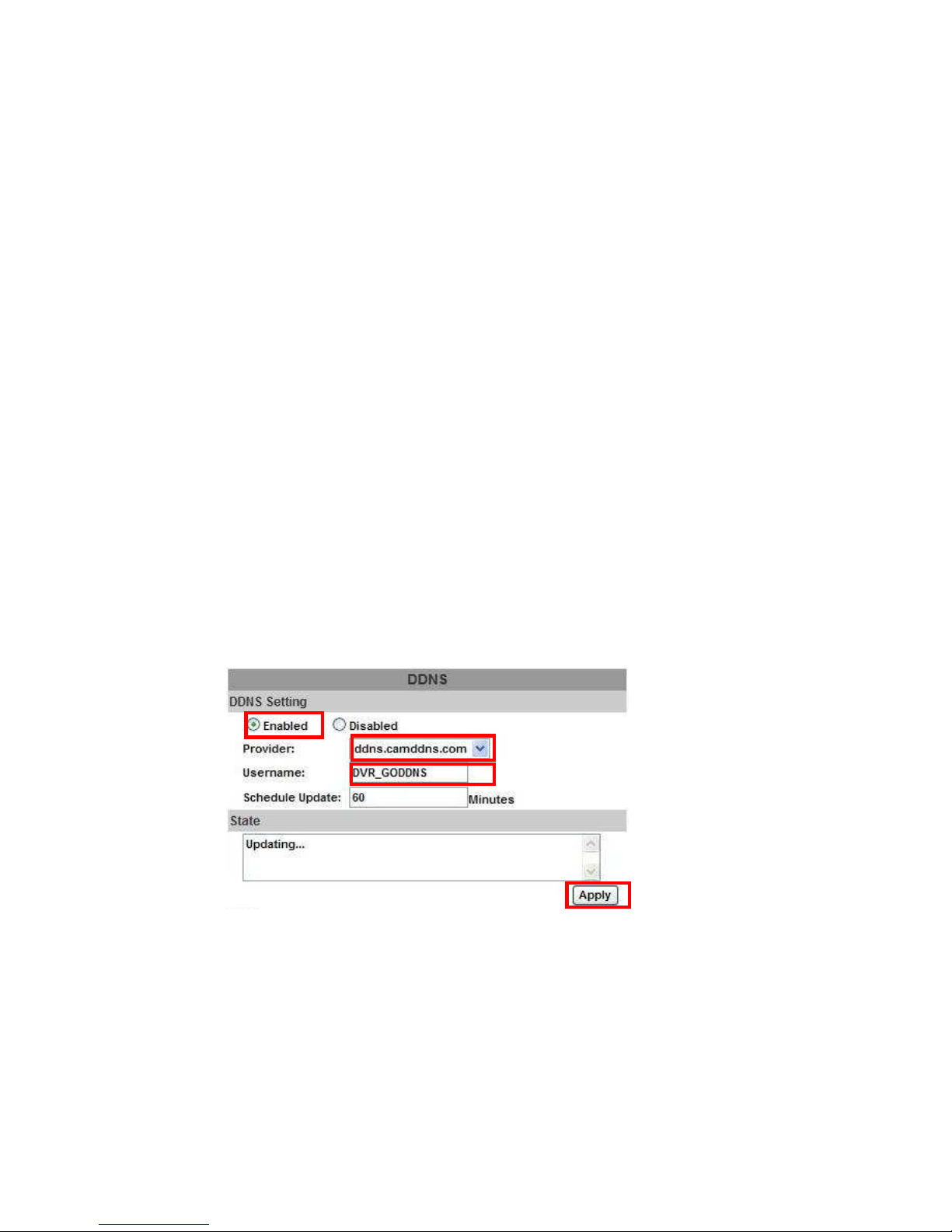
DDNS SETTING – DDNS.CAMDDNS.COM
PROVIDER: Select ddns.camddns.com
USERNAME: The registered username in DDNS.CAMDDNS.COM.
SCHEDULE UPDATE: A period of time to update IP address.
STATE
1. Updating: Information update.
2. Idle: Stop service.
3. DDNS registered successfully, now log by
http://<username>.ddns.camddns.com: Registered successfully.
4. Updating Failed, the name is already registered.
5. Updating Failed, please check your internet connection.
DDNS Setting Steps:
Press ○1 “ENABLE” option to enable DDNS function and select ○2
“ddns.camddns.com” of the provider drop down list which is suggested to use. In
the following, insert ○3 the username which the user wants to apply
(i.e. DVR_GODDNS in here). After that, click ○4 “Apply” button to apply a
DDNS domain name.
1.
2.
3.
4.
Page 64
64
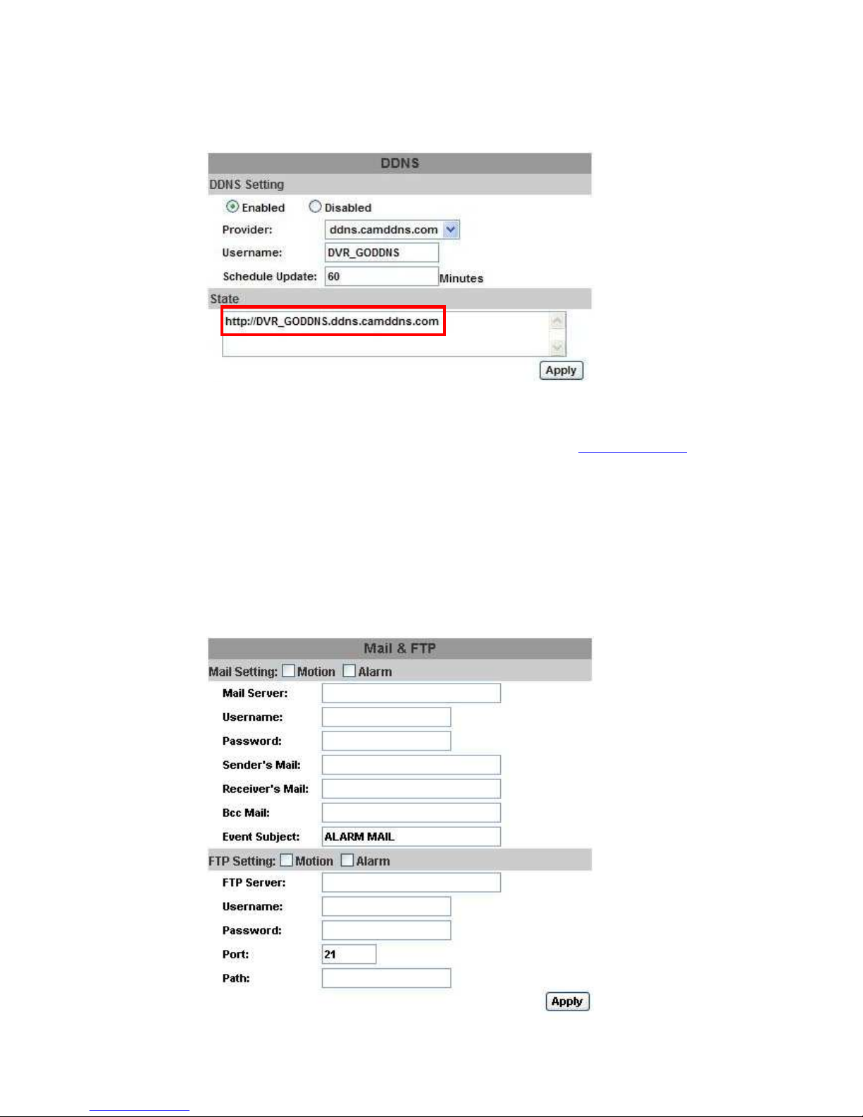
Finally, the DVR domain name○5 (http://DVR_GODDNS.ddns.camddns.com)
will be shown on the state block.
NOTE: 1. If the user selects another provider which is ddns2.ydsdvr.com, all of the setting
steps are the same with ddns.camddns.com setting.
2. However, if dyndns.org provider is selected, please go to www.dyndns.org website
to register the account first. The user has to fill in the username, password and
hostname for applying the account. After the user applied the account successfully,
the dyndns.org will give the user a complete DDNS domain name.
3. If setting up IP schedule update too frequently, the IP may be blocked. In general,
schedule update every day (1440 minutes) is recommended.
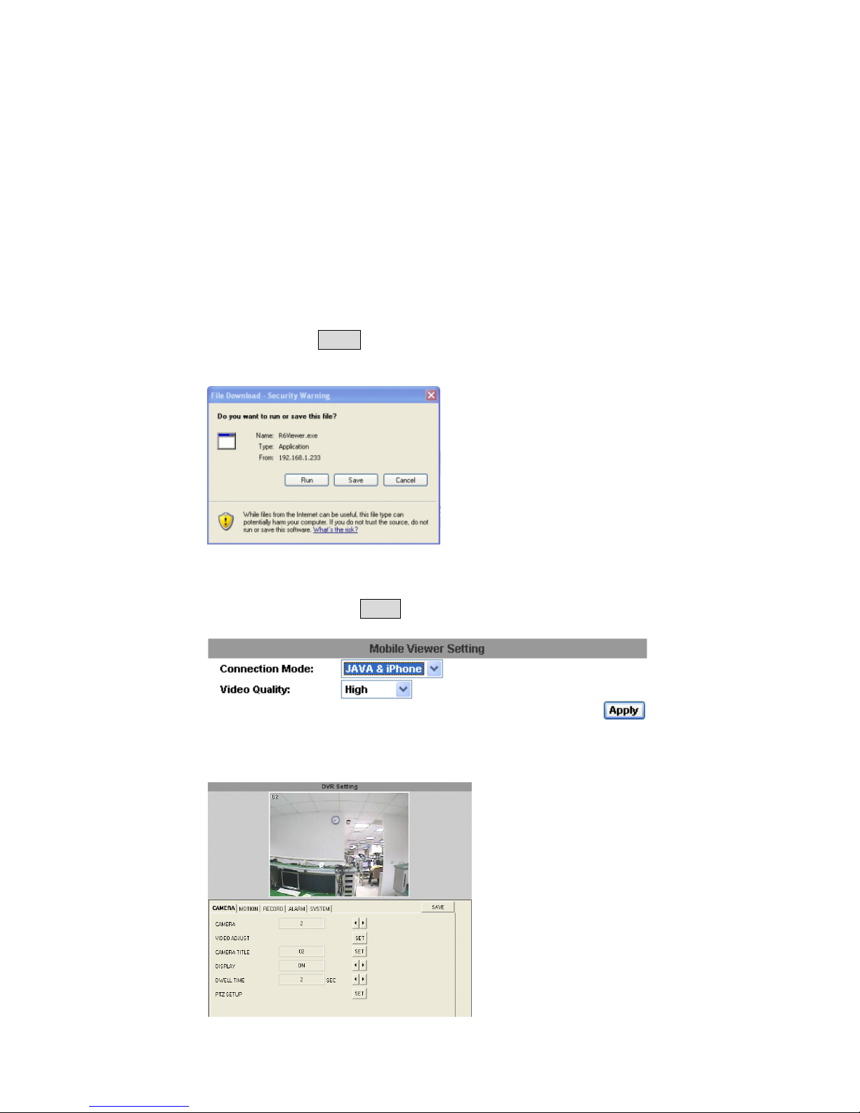
G. NETWORK / Mail & FTP
Click on “Motion” or “Alarm” option to enable Mail Setting and FTP Setting
function.
5.
Page 65
65
Mail Server: The IP address of Mail Server (i.e. mail.huntelec.com.tw).
Username: The username while log in to the mail server.
Password: The password while log in to the mail server.
Sender’s Mail: The sender’s account when send the mail via this mail server.
Receiver’s Mail: The receiver’s mail address.
Bcc Mail: The receiver’s mail address for Bcc Mail.
Event Subject: The subject of this mail. (Default value is ALARM MAIL)
FTP Server: The IP address of FTP Server.
Username: The username while log in to the ftp server.
Password: The password while log in to the ftp server.
Port: The port number of file transmission. (Default value is 21)
Path: The ftp path where the user wants to reserve the information.
Finally, click on Apply button to reserve the setting.
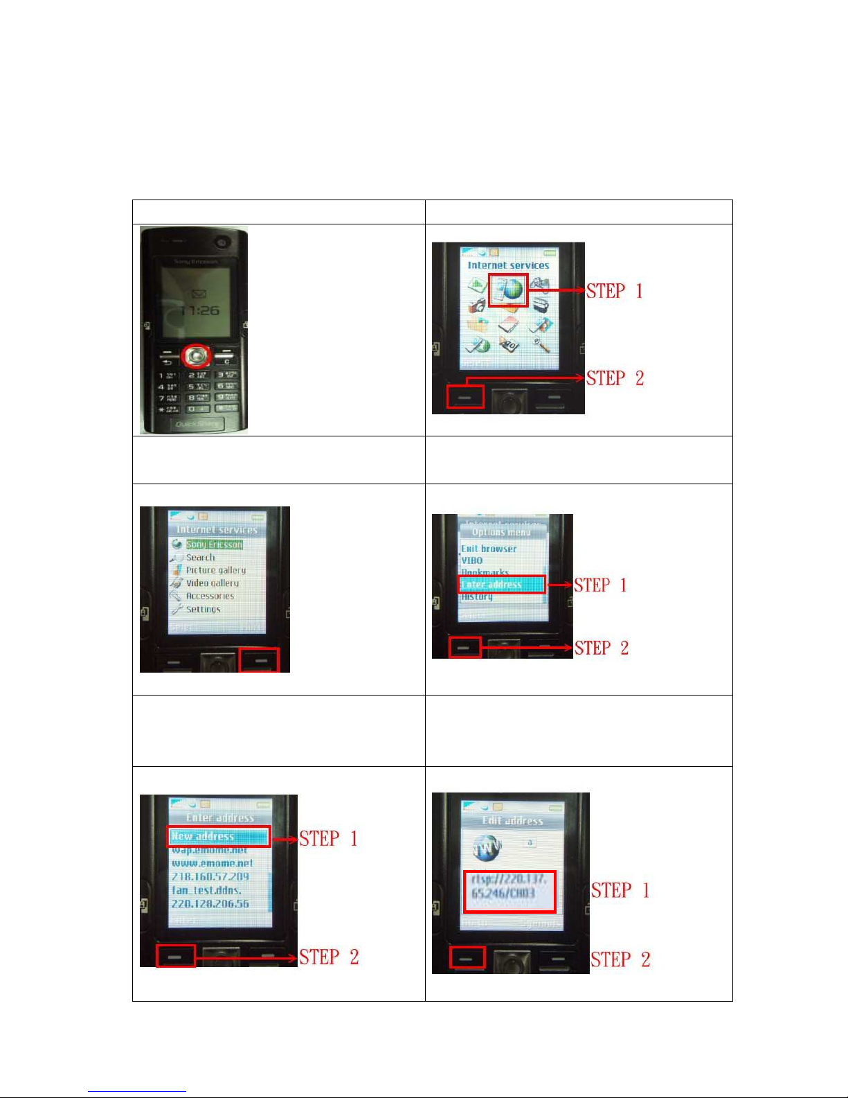
H. OTHERS / Player Downloaded
User can click “Run” button to download the player to local PC.
I. OTHERS/ Mobile Viewer
Click the drop down list of connection mode to select the sort of mobile viewer
connection. Then click Apply to reserve the setting. There are JAVA / IPhone and
3GPP (MPEG4) two options. Moreover, the video quality can be setup as well.
J. OTHERS / DVR Setting
DVR setting can be changed via the Internet.
Page 66
66
7 3GPP APPLICATION & SETTING
3GPP (also known as 3rd Generation Partnership Project) is a corporation which formulate
3rd-generation communication standard specification. Via this wireless communication
protocol, the 3G mobile can perform the remote control. The following example is operated by
Sony Ericsson 3G mobile phone:
1. Press MENU KEY to get into menu.
2. Select Internet services
3. In the Internet services page, press
More KEY
4. Select Enter address, and press Select
KEY
5. Select New address,and press Enter
KEY
6. Fill in address rtsp:// <<IP>>/channel
(rtsp://220.137.65.246/CH03) and press Go
To KEY.
Page 67

67
7. “Connected to media server” will
appear
8. Success with vivid image
* 1. 3GPP BANDWIDTH: Minimum 30kbit /sec. per channel.
2. CONNECTION NUMBERS: Maximum 16 people per channel.
Page 68
68
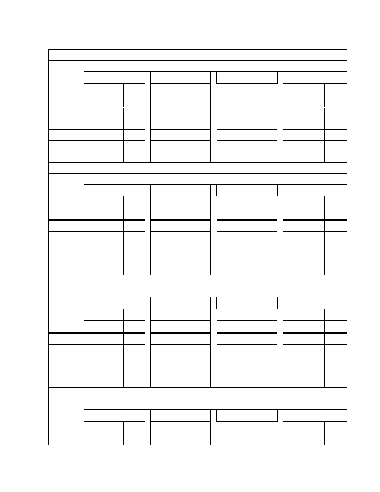
APPENDIX A: RECORDING TIME LAPSE (HOURS)
FULL D1- 720x480
160 GB Hard Disk
Unit: Hour
PICTURE QUALITY(KB)
LOW
MEDIUM
HIGH
BEST
simple complex average
simple complex average
simple complex average
simple complex average
Recording
Speed
(IPS)
0.80 5.63 3.52
4.38 10.38 6.78
3.64 13.43 8.98
5.60 17.06 15.66
60 970
137 553
190
74 132
213
57 135
138 45 91
30 1941 275 1108
380 149 264
426 115 270
277 91 184
15 3883 551 2217
761 299 530
853 231 542
554 182 368
8 7281 1034 4157
1427 560 993
1600 433 1016
1040 341 690
4 14563 2068 8315
2855 1121 1988
3200 867 2033
2080 683 1381
250 GB Hard Disk Unit: Hour
PICTURE QUALITY(KB)
LOW
MEDIUM
HIGH
BEST
simple complex average
simple complex average
simple complex average
simple complex average
Recording
Speed
(IPS)
0.80 5.63 3.52
4.38 10.38 6.78
3.64 13.43 8.98
5.60 17.06 15.66
60 1517 215 866
297 116 206
333
90 211
216 71 143
30 3034 430 1732
594 233 413
666 180 423
433 142 287
15 6068 861 3464
1189 467 828
1333 361 847
866 284 575
8 11377 1616 6496
2230 876 1553
2500 677 1588
1625 533 1079
4 22755 3232 12993
4461 1753 3107
5001 1355 3178
3250 1067 2158
400 GB Hard Disk
Unit: Hour
PICTURE QUALITY(KB)
LOW
MEDIUM
HIGH
BEST
simple complex average
simple complex average
simple complex average
simple complex average
Recording
Speed
(IPS)
0.80 5.63 3.52
4.38 10.38 6.78
3.64 13.43 8.98
5.60 17.06 15.66
60 2427 344 1385
475 186 330
533 144 338
346 113 229
30 4854 689 2771
951 373 662
1066 289 677
693 227 460
15 9709 1379 5544
1903 747 1325
2133 578 1355
1387 455 921
8 18204 2585 10394
3569 1402 2485
4000 1084 2542
2600 853 1726
4 36408 5171 20789
7138 2804 4971
8001 2168 5084
5201 1707 3454
500 GB Hard Disk Unit: Hour
PICTURE QUALITY(KB)
LOW
MEDIUM
HIGH
BEST
simple complex average
simple complex average
simple complex average
simple complex average
Recording
Speed
(IPS)
0.80 5.63 3.52
4.38 10.38 6.78
3.64 13.43 8.98
5.60 17.06 15.66
Page 69

69
60 3034 430 1732
549 233 413
666 180 423
433 142 287
30 6068 861 3464
1189 467 828
1333 361 847
866 284 575
15 12136 1723 6929
2379 934 1656
2667 722 1694
1733 569 1151
8 22755 3232 12993
4461 1753 3107
5001 1355 3178
3250 1067 2158
4 45511 6464 25987
8923 3506 6214 10002 2710 6356
6501 2134 4317
750 GBHard Disk
Unit: Hour
PICTURE QUALITY(KB)
LOW
MEDIUM
HIGH
BEST
simple complex average
simple complex average
simple complex average
simple complex average
Recording
Speed
(IPS)
0.80 5.63 3.52
4.08 10.38 6.78
3.64 13.43 8.98
5.60 17.06 15.66
60 4551 646 2598
892 350 621
1000 271 635
650 213 431
30 9102 1292 5197
1784 701 1242
2000 542 1271
1300 426 863
15 18204 2585 10349
3569 1402 2485
4000 1084 2542
2600 853 1726
8 34133 4848 19490
6692 2629 4660
7501 2032 4766
4876 1601 3238
4 68266 9696 38981
13385 5259 9322 15003 4065 9534
9752 3202 6477
1THard Disk Unit: Hour
PICTURE QUALITY(KB)
LOW
MEDIUM
HIGH
BEST
simple complex average
simple complex average
simple complex average
simple complex average
Recording
Speed
(IPS)
0.80 5.63 3.52
4.08 10.38 6.78
3.64 13.43 8.98
5.60 17.06 15.66
60 6068 861 3464
1189 467 828
1333 361 847
866 284 575
30 12136 1723 6929
2379 934 1656
2667 722 1694
1733 569 1151
15 24272 3447 13859
4759 1869 3314
5334 1445 3389
3467 1138 2302
8 45511 6464 25987
8923 3506 6214 10002 2710 6356
6501 2134 4317
4 91022 12929 51975
17847 7012 12429
20004 5421 12712
13003 4269 8636
Page 70
70
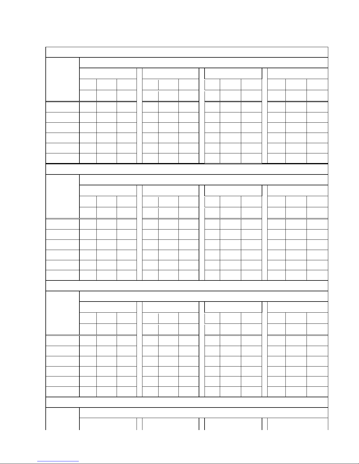
HALF D1- 720x240
160 GB Hard Disk
Unit: Hour
PICTURE QUALITY (KB)
LOW
MEDIUM
HIGH
BEST
simple complex average
simple complex average
simple complex average
simple complex average
Recording
Speed
(PPS)
1.00 3.80 2.40
2.00 6.00 4.00
5.00 10.00 7.50
6.00 17.00 11.50
120 388 102 245
194
64 129
77 38 57
64 22 43
60 776
204 490
388 129 258
155
77 116
129 45 87
30 1553 408 980
776 258 517
310 155 232
258 91 174
15 3106 817 1961
1553 517 1035
621 310 465
517 182 349
8 5825 1533 3679
2912 970 1941
1165 582 873
970 342 656
4 11650 3066 7358
5825 1941 3883
2330 1165 1747
1941 685 1313
250 GB Hard Disk Unit: Hour
PICTURE QUALITY (KB)
LOW
MEDIUM
HIGH
BEST
simple complex average
simple complex average
simple complex average
simple complex average
Recording
Speed
(PPS)
1.00 3.80 2.40
2.00 6.00 4.00
5.00 10.00 7.50
6.00 17.00 11.50
120 606 159 382
303 101 202
121
60 90
101 35 68
60 1213 319 766
606 202 404
242 121 181
202 71 136
30 2427 638 1532
1213 404 808
485 242 363
404 142 273
15 4854 1277 3065
2427 809 1618
970 485 727
809 285 547
8 9102 2395 5748
4551 1517 3034
1820 910 1365
1517 535 1026
4 18204 4790 11497
9102 3034 6068
3640 1820 2730
3034 1070 2052
400 GB Hard Disk Unit: Hour
PICTURE QUALITY (KB)
LOW
MEDIUM
HIGH
BEST
80 GB Hard Disk Unit: Hour
PICTURE QUALITY (KB)
LOW
MEDIUM
HIGH
BEST
simple complex average
simple complex average
simple complex average
simple complex average
Recording
Speed
(PPS)
1.00 3.80 2.40
2.00 6.00 4.00
5.00 10.00 7.50
6.00 17.00 11.50
120 194
51 122
97 32 64
38 19 28
32 11 21
60 388
102 245
194
64 129
77 38 57
64 22 43
30 776
204 490
388 129 258
155
77 116
129 45 87
15 1553 408 980
776 258 517
310 155 232
258 91 174
8 2912 766 1839
1456 485 970
582 291 436
485 171 328
4 5825 1533 3679
2912 970 1941
1165 582 873
970 342 656
Page 71

71
simple complex average
simple complex average
simple complex average
simple complex average
(PPS)
1.00 3.80 2.40
2.00 6.00 4.00
5.00 10.00 7.50
6.00 17.00 11.50
120 970 255 612
485 161 323
194
97 145
161 57 109
60 1941 511 1226
970 323 646
388 194 291
323 114 218
30 3883 1022 2452
1941 647 1294
776 388 582
647 228 437
15 7767 2044 4905
3883 1294 2588
1553 776 1164
1294 456 875
8 14563 3832 9197
7281 2427 4854
2912 1456 2184
2427 856 1641
4 29127 7665 18396
14563 4854 9708
5825 2912 4368
4854 1713 3283
750 GB Hard Disk Unit: Hour
PICTURE QUALITY (KB)
LOW
MEDIUM
HIGH
BEST
simple complex average
simple complex average
simple complex average
simple complex average
Recording
Speed
(PPS)
1.00 3.80 2.40
2.00 6.00 4.00
5.00 10.00 7.50
6.00 17.00 11.50
120 1820 479 1149
910 303 606
364 182 273
303 107 205
60 3640 958 2299
1820 606 1213
728 364 546
606 214 410
30 7281 1916 4598
3640 1213 2426
1456 728 1092
1213 428 820
15 14563 3832 9197
7281 2427 4854
2912 1456 2184
2427 856 1641
8 27306 7185 17245
13653 4551 9102
5461 2730 4095
4551 1606 3078
4 54613 14371 34492
27306 9102 18204
10922 5461 8191
9102 3212 6157
1T Hard Disk Unit: Hour
PICTURE QUALITY (KB)
LOW
MEDIUM
HIGH
BEST
simple complex average
simple complex average
simple complex average
simple complex average
Recording
Speed
(PPS)
1.00 3.80 2.40
2.00 6.00 4.00
5.00 10.00 7.50
6.00 17.00 11.50
120 2427 638 1532
1213 404 808
485 242 363
404 142 273
60 4854 1277 3065
2427 809 1618
970 485 727
809 285 547
500 GB Hard Disk
Unit: Hour
PICTURE QUALITY (KB)
LOW
MEDIUM
HIGH
BEST
simple complex average
simple complex average
simple complex average
simple complex average
Recording
Speed
(PPS)
1.00 3.80 2.40
2.00 6.00 4.00
5.00 10.00 7.50
6.00 17.00 11.50
120 1213 319 766
606 202 404
242 121 181
202 71 136
60 2427 638 1532
1213 404 808
485 242 363
404 142 273
30 4854 1277 3065
2427 809 1618
970 485 727
809 285 547
15 9709 2555 6132
4854 1618 3236
1941 970 1455
1618 571 1094
8 18204 4790 11497
9102 3034 6068
3640 1820 2730
3034 1070 2052
4 36408 9581 22994
18204 6068 12136
7281 3640 5460
6068 2141 4104
Page 72

72
30 9709 2555 6132
4854 1618 3236
1941 970 1455
1618 571 1094
15 19418 5110 12264
9709 3236 6472
3883 1941 2912
3236 1142 2189
8 36408 9581 22994
18204 6068 12136
7281 3640 5460
6068 2141 4104
4 72817 19162 45989
36408 12136 24272
14563 7281 10922
12136 4283 8209
Page 73
73
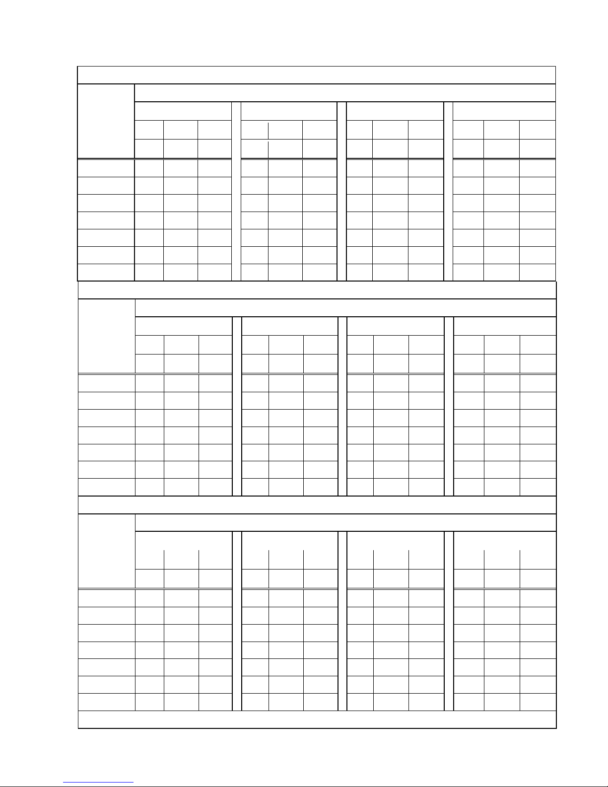
CIF-360x240
80 GB Hard Disk Unit: Hour
PICTURE QUALITY (KB)
LOW
MEDIUM
HIGH
BEST
simple complex average
simple complex average
simple complex average
simple complex average
Recording
Speed
(PPS)
0.50 1.90 1.20
1.00 3.00 2.00
2.50 5.00 3.75
3.00 8.75 5.88
240 194
51 122
97 32 64
38 19 28
32 11 21
120 388 102 245
194
64 129
77 38 57
64 22 43
60 776
204 490
388 129 258
155
77 116
129 44 86
30 1553 408 980
776 258 517
310 155 232
258 88 173
15 3106 817 1961
1553 517 1035
621 310 465
517 177 347
8 5825 1533 3679
2912 970 1941
1165 582 873
970 332 651
4 11650 3066 7358
5825 1941 3883
2330 1165 1747
1941 665 1303
160 GB Hard Disk Unit: Hour
PICTURE QUALITY (KB)
LOW
MEDIUM
HIGH
BEST
simple complex average
simple complex average
simple complex average
simple complex average
Recording
Speed
(PPS)
0.50 1.90 1.20
1.00 3.00 2.00
2.50 5.00 3.75
3.00 8.75 5.88
240 388 102 245
194
64 129
77 38 57
64 22 43
120 776 204 490
388 129 258
155 77 116
129 44 86
60 1553 408 980
776 258 517
310 155 232
258 88 173
30 3106 817 1961
1553 517 1035
621 310 465
517 177 347
15 6213 1635 3924
3106 1035 2070
1242 621 931
1035 355 695
8 11650 3066 7358
5825 1941 3883
2330 1165 1747
1941 665 1303
4 23301 6132 14716
11650 3883 7766
4660 2330 3495
3883 1331 2607
250 GB Hard Disk Unit: Hour
PICTURE QUALITY (KB)
LOW
MEDIUM
HIGH
BEST
simple complex average
simple complex average
simple complex average
simple complex average
Recording
Speed
(PPS)
0.50 1.90 1.20
1.00 3.00 2.00
2.50 5.00 3.75
3.00 8.75 5.88
240 606 159 382
303 101 202
121 60 90
101 34 67
120 1213 319 766
606 202 404
242 121 181
202 69 135
60 2427 638 1532
1213 404 808
485 242 363
404 138 271
30 4854 1277 3065
2427 809 1618
970 485 727
809 277 543
15 9709 2555 6132
4854 1618 3236
1941 970 1455
1618 554 1086
8 18204 4790 11497
9102 3034 6068
3640 1820 2730
3034 1040 2037
4 36408 9581 22994
18204 6068 12136
7281 3640 5460
6068 2080 4074
400 GB Hard Disk Unit: Hour
Page 74
74
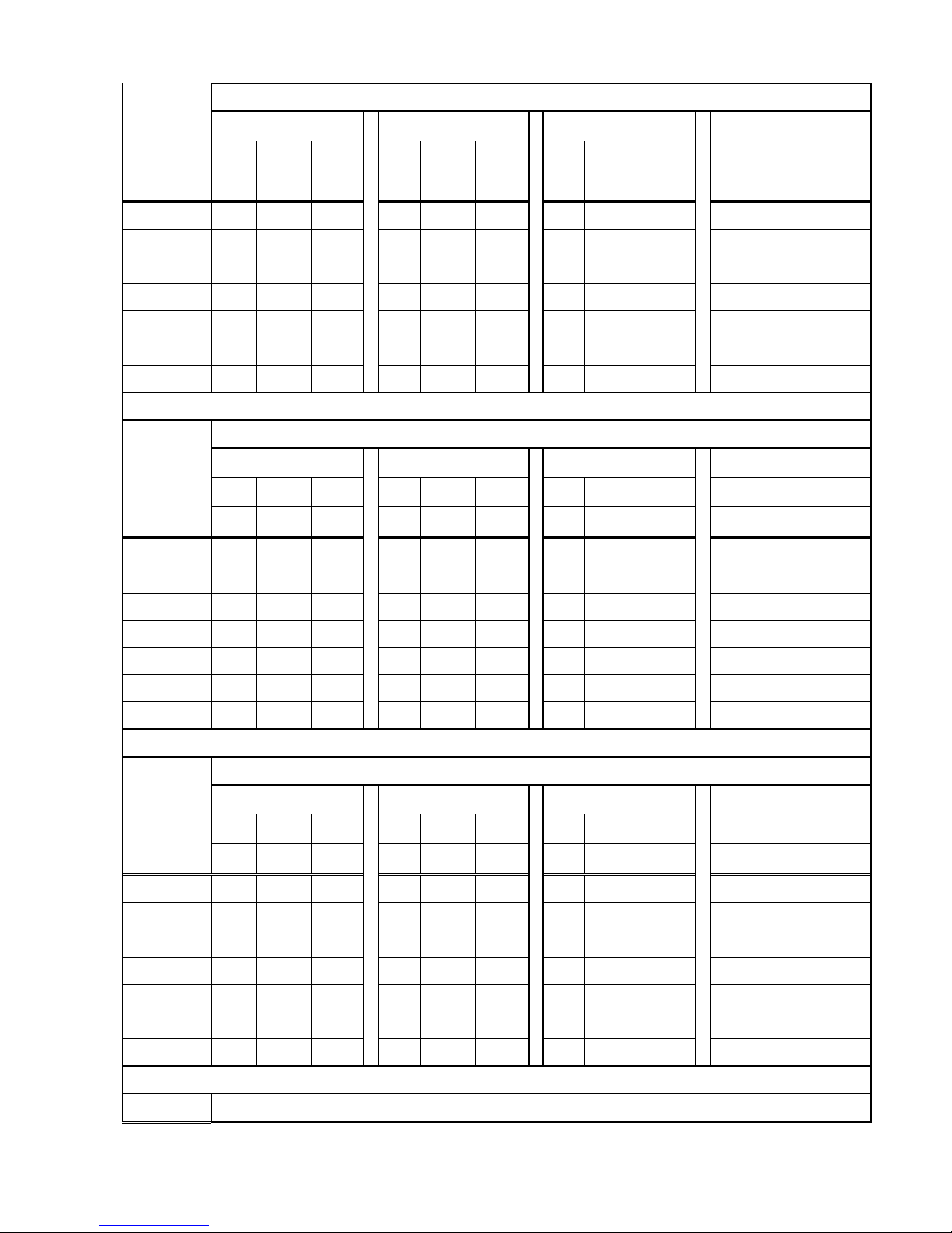
PICTURE QUALITY (KB)
LOW
MEDIUM
HIGH
BEST
simple complex average
simple complex average
simple complex average
simple complex average
Recording
Speed
(PPS)
0.50 1.90 1.20
1.00 3.00 2.00
2.50 5.00 3.75
3.00 8.75 5.88
240 970 255 612
485 161 323
194 97 145
161 55 108
120 1941 511 1226
970 323 646
388 194 291
323 110 216
60 3883 1022 2452
1941 647 1294
776 388 582
647 221 434
30 7767 2044 4905
3883 1294 2588
1553 776 1164
1294 443 868
15 15534 4088 9811
7767 2589 5178
3106 1553 2329
2589 887 1738
8 29127 7665 18396
14563 4854 9708
5825 2912 4368
4854 1664 3259
4 58254 15330 36792
29127 9709 19418
11650 5825 8737
9709 3328 6518
500 GB Hard Disk Unit: Hour
PICTURE QUALITY (KB)
LOW
MEDIUM
HIGH
BEST
simple complex average
simple complex average
simple complex average
simple complex average
Recording
Speed
(PPS)
0.50 1.90 1.20
1.00 3.00 2.00
2.50 5.00 3.75
3.00 8.75 5.88
240 1213 319 766
606 202 404
242 121 181
202 69 135
120 2427 638 1532
1213 404 808
485 242 363
404 138 271
60 4854 1277 3065
2427 809 1618
970 485 727
809 277 543
30 9709 2555 6132
4854 1618 3236
1941 970 1455
1618 554 1086
15 19418 5110 12264
9709 3236 6472
3883 1941 2912
3236 1109 2172
8 36408 9581 22994
18204 6068 12136
7281 3640 5460
6068 2080 4074
4 72817 19162 45989
36408 12136 24272
14563 7281 10922
12136 4161 8148
750 GB Hard Disk Unit: Hour
PICTURE QUALITY (KB)
LOW
MEDIUM
HIGH
BEST
simple complex average
simple complex average
simple complex average
simple complex average
Recording
Speed
(PPS)
0.50 1.90 1.20
1.00 3.00 2.00
2.50 5.00 3.75
3.00 8.75 5.88
240 1820 479 1149
910 303 606
364 182 273
303 104 203
120 3640 958 2299
1820 606 1213
728 364 546
606 208 407
60 7281 1916 4598
3640 1213 2426
1456 728 1092
1213 416 814
30 14563 3832 9197
7281 2427 4854
2912 1456 2184
2427 832 1629
15 29127 7665 18396
14563 4854 9708
5825 2912 4368
4854 1664 3259
8 54613 14371 34492
27306 9102 18204
10922 5461 8191
9102 3120 6111
4 109226 28743 68984
54613 18204 36408
21845 10922 16383
18204 6241 12222
1T Hard Disk Unit: Hour
Recording PICTURE QUALITY (KB)
Page 75

75
LOW
MEDIUM
HIGH
BEST
simple complex average
simple complex average
simple complex average
simple complex average
Speed
(PPS)
0.50 1.90 1.20
1.00 3.00 2.00
2.50 5.00 3.75
3.00 8.75 5.88
240 2427 638 1532
1213 404 808
485 242 363
404 138 271
120 4854 1277 3065
2427 809 1618
970 485 727
809 277 543
60 9709 2555 6132
4854 1618 3236
1941 970 1455
1618 554 1086
30 19418 5110 12264
9709 3236 6472
3883 1941 2912
3236 1109 2172
15 38836 10220 24528
19418 6472 12945
7767 3883 5825
6472 2219 4345
8 72817 19162 45989
36408 12136 24272
14563 7281 10922
12136 4161 8148
4 145635 38325 91980
72817 24272 48544
29127 14563 21845
24272 8322 16297
* The value is for reference only
Page 76

76
APPENDIX B: HDD COMPATIBLE TABLE
Brand
Model
Capacity others
SEAGATE STM3250820AS 250 GB 7200 10
ST3250310SV 250GB SV35.3
ST3400620AS 400 GB 7200 10
ST3500320SV 500GB SV35.3
ST3500320AS 500GB 7200 11
ST3500418AS 500GB 7200 12
ST3750640AS 750 GB 7200 10
ST3750330AS 750 GB 7200 11
ST31000333AS 1TB 7200 11
ST31000340AS 1TB 7200 11
ST31000340NS 1TB Barracuda ES.2
ST31000340SV 1TB SV35.3
ST31500341AS 1.5TB 7200 11
WD WD1600AAJS 160 GB 7200 CB
WD2500AAKS 250 GB 7200 CB
WD2500AVVS 250 GB 7200 GP
WD5000AACS 500 GB 7200 GP
WD5000AVVS 500 GB 7200 GP
WD5000AAKS 500GB 7200 CB
WD6400AAKS 640 GB 7200 BLUE
WD6400AVVS 640 GB 7200 GP
WD7500AACS 750GB 7200 GP
WD7500AVVS 750GB 7200 GP
WD10EACS 1TB 7200 GP
WD10EADS 1TB Caviar Green
WD10EVDS 1TB Green Power
WD10EVVS 1TB 7200 GP
WD15EADS 1.5TB 7200 GP
WD15EARS 1.5TB 7200 GP
WD20EADS 2.0TB 7200 GP
HITACHI HDS721616PLA380 160 GB 7200
HDT725025VLA380 250 GB 7200
HDT725032VLA360 320 GB 7200
HDP725050GLA360 500 GB 7200
HCP725050GLA380 500GB 7200
HDT721010SLA360 1TB 7200
* The compatible table is for reference only
Page 77

77
APPENDIX C: ERROR MESSAGE LIST
ERROR MESSAGE ERROR STATUS & REASON NOTE
DISK ACCESS ERROR! H.D.D. Data structure Un-normal.
Data does not record into DVR or bad sector on DVR
H.D.D. Please install another H.D.D. and perform the record
again.
UPDATE FILE ERROR! Please re-download the update file and update again.
FIRMWARE UPGRADE
FAILED
Please reboot the DVR and upgrade the firmware. Please
send the DVR back to repair when DVR is disability.
MEDIA ACCESS FAIL! The USB file format is incorrect (Please format the pen
drive to FAT32) or Pen Drive is setup to ONLY READ mode
(Please annul ONLY READ mode) when reserve the data by
using Pen Drive. The data cannot be burn into CD/DVD
disc. Please change another CD/DVD disc and backup the
file in CD/DVD disc storage.
NO FILE! There is no upgrade file within Pen Drive or the name of
upgrade file does not correspond with DVR format. Please
adjust the upgrade file name based on the following
information.
16CH -> UpdateR.bin
08CH -> Update8.bin
04CH -> Update4.bin
USB DEVICE NOT FOUND
NO USB
Pen Drive undetected. Please Unplug the Pen Drive and plug
it again.
BACKUP START TIME
ERROR
Backup start time error.
BACKUPEND TIME ERROR Backup end time error.
DISK ERROR The data cannot be burn into CD/DVD disc. Please change
another CD/DVD disc and backup the file.
FAN FAILED Fan Error Warning.
NO LOG DATA No Events Record.
SCHEDULE RECORD The condition is caused by trying to stop recording when
perform the schedule record. Please setup the record to
manual mode and then stop the record.
PLEASE SELECT ONE
CAMERA
The message will be shown while using the ZOOM function
under split screen condition. Please switch the screen into
full screen mode and then operate the ZOOM function.
V1.1_091231
 Loading...