


MANUAL
HOUSINGS
Likuid L07-L19-L37-L61-L91
Fecha | Date:
09/09/2013
Código Doc. | Document N:
M-Housings-R04
MANUAL
HOUSINGS
Likuid L07-L19-L37-L61-L91
MANUAL
M-Housings -R04
Page 3 of 8
1. INTRODUCTION
This user manual describes the technical characteristics and the instructions for operation, maintenance, assembling and
disassembling of Likuid housings. With the aim of guaranteeing an optimum performance, it is strongly recommended to follow
scrupulously the following indications.
The design of the housings has been validated under the corresponding quality control protocols, so that the optimum performance
is guaranteed in accordance to technical specifications.
When the product is received and/or unpacked:
• Ask for assistance of qualified technicians for ensuring that the installation is made correctly.
• Please inform Likuid immediately of any external damage or defect in the packing or in the product itself.
• Follow scrupulously the drawings supplied for housings assembling/disassembling.
2. TECHNICAL SPECIFICATIONS
The main characteristics of Likuid’s housings are the following:
Material
Stainless steel
(diverse range)
Morph
ology
Tubular
Range of pH resistance
0-14
Maximum pressure
1
10 bar
Range of temperature
1 5-95ºC
Fluid2
Group
2
Standard models
L7, L19, L37, L61, L9
1
1
According to 97/23/CE Directive, in applicable technical requirements of Article 3-Section 3
2
For fluids from the Group II, according to 97/23/CE Directive, in applicable technical requirements of Article 3-Section 3
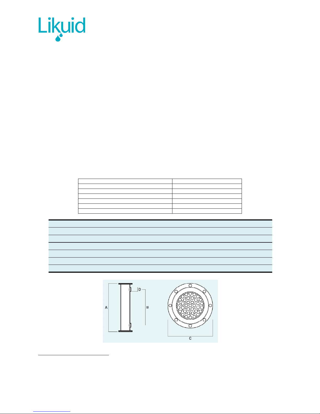
L07 L19 L37 L61 L91
A
1195mm 1195mm 1195mm 1195mm 1195mm
B
880mm 880mm 880mm 880mm 880mm
C
DN100 DN150 DN200 DN300 DN350
D
Ø53mm Ø77mm Ø96mm Ø110mm Ø128mm
Q
7 membranes 19 membranes 37 membranes 61 membranes 91 membranes
M
23kg 46kg 73kg 138kg 186kg

MANUAL
M-Housings -R04
Page 4 of 8
3. LIST OF COMPONENTS
The standard supply consists on the following components:
•
1 Housing
•
Assembling supplements (Double screws – M5 y M6 + Washers M5 + Nuts M5)
•
2 back-plates (with and without hole-reductions)
•
2 flat gaskets for housing/pipes connection
•
2 O-rings for permeate pipes connection
•
O-rings for membranes (quantity depends on model)
•
Mounting screws M6 (quantity depends on model)
•
Ceramic membranes (quantity depends on model)
The unit is delivered as a complete assembled set (with the exception of 2 flat gaskets and assembling supplements).
There is a possibility to include accessories for permeate:
• DIN2576 flange
• Ready to weld
• Clamp
• Blind
Others, consult Likuid.
The dimensions of the permeate connections for each housing model are included in the table below:
Hydraulic diam. Threads position Screws
L07
DN12 DN06 M6
L19
DN20 DN10 M8
L37
DN32 DN20 M10
L61
DN40 DN25 M12
L91
DN50 DN32 M14

MANUAL
M-Housings -R04
Page 5 of 8
4. ASSEMBLING INSTRUCTIONS
4.1. ASSEMBLING OF MODULES:
The sequence for the assembling of modules is described below:
STEP DESCRIPTION GRAFICAL SCHEME
1
Screw in completely the assembling supplements,
by the M6 end, in the upper plate of the module.
Upper plate of the module: with the module in
vertical position, upper part with respect to the
identification label
(Orange pieces)
2
Install the back-plate which has the holereductions, turned over 180º respecting its
permanent position. It must have the holereductions next to the plate, fully in contact with
the assembling supplements.
(Pink piece)
3
Fix the assembling supplements with the
corresponding M5 washers and nuts.
(Yellow pieces)
4
In horizontal position of the module, insert
carefully the ceramic membranes by the opposite
side, until reaching the stop in the back-plate
previously installed. Membranes must be inserted
from the bottom to the top.

MANUAL
M-Housings -R04
Page 6 of 8
STEP
DESCRIPTION GRAFICAL SCHEME
5
After installing the membranes, put the second
back-plate (without hole-reductions). Use the Orings and mounting screws M6.Torque approx.
10 Nm. Membranes must protrude approx. 4 mm
from the plate.
The screws must be tightened crosswise. Since
this operation allows the O-rings to be tightened
and provides the water-tightness of the module, it
must be done carefully and uniformly.
NOTE: only one membrane is represented in the
picture.
6
Release the initially installed back-plate (with
hole-reductions), turn it over 180º and repeat the
instruction 5. Membranes are now mounted in the
housing.
4.2. ASSEMBLING OF MODULES:
•
After unscrewing the screws in the back-plate of both sides, back-plates must be extracted carefully. Sometimes, back-plate
can be stuck to the plate due to the high operating pressure. For these cases, the back-plates have some M5 threaded holes
(marked with arrows in the picture below) where screws can be inserted and used as extractors, so that when they are
tightened, pressure is applied on the plate and the back-plate is extracted from the housing.
• After removing the back-plates from both sides, remove the O-rings from one side carefully (Don’t use Sharp tools).
• Remove the membranes from the side where the O-rings are still present. Be careful: membranes are just hold at the tips of
the module.

MANUAL
M-Housings -R04
Page 7 of 8
4.3. OTHERS
It is recommended NOT to reuse the O-rings.
If substantial vibrations are thought to occur, it is recommended to use fixing glue for screws.
Tools for manipulation/elevation of housings must be available for manipulating heavy modules.
5. WARRANTY
Unless there is an explicit contractual specification that modifies the general warranty conditions, Likuid modules are guaranteed
against all manufacturing or assembling faults for a period of 12 months from the starting-up, or 15 months from the date of
purchase.

MANUAL
M-Housings -R04
Page 8 of 8
 Loading...