

Likewise 052-4316-2 Owner's Manual
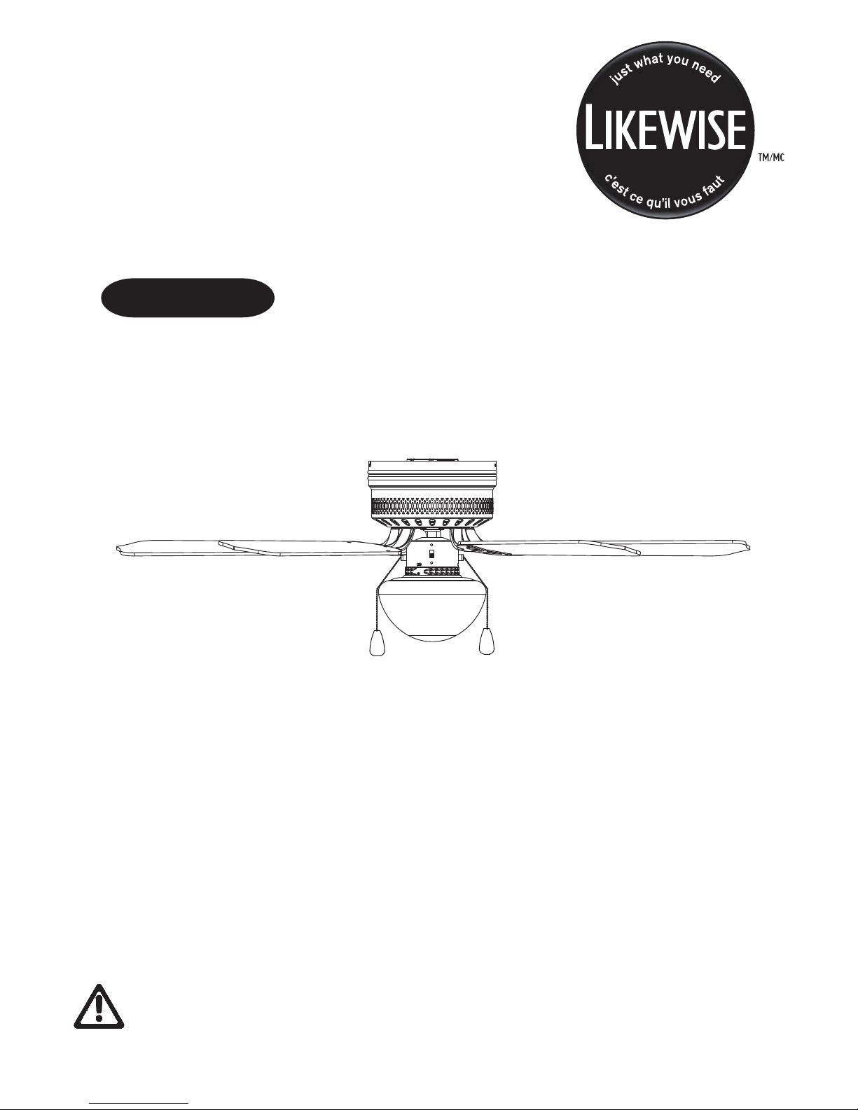
42" Hugger Ceiling FAN
OWNER’S MANUAL
052-4316-2
Caution!
For your safety, please read and understand this manual before installing or operating this
V3. 2016
product.

Table of Contents
Technical Data
Important Safety Instructions
Parts List
Parts Locations
Before Installation
Installation
Operation
Care and Maintenance
Troubleshooting
Environmental Protection
Warranty
2
2
3
4
5
6-7
7-11
11-12
12
13
14
14
Operating voltage
Power consumption
Bulbs
120 V, 60 Hz
Fan only: 45 W (Maximum)
One E12 candelabra-base bulb (60 W maximum)
Whenitcomestoproductsforyourhome,it’sessential
theystandup totherealitiesofeverydayfamilylife.
TM
Designedwithyourfamilyinmind,ForLiving products
combinetimelessstyleandfamily-friendlyfeatures.
Nowyoucanfocusonwhat’simportant creating
lastingmemorieswithyourfamily.
2
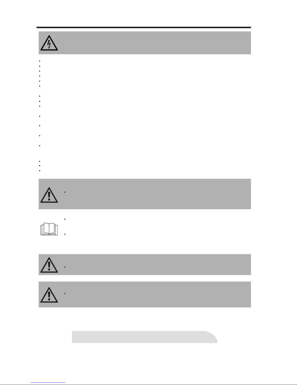
WARNING!
To avoid possible electric shock, switch off the power supply at the main fuse or
circuit breaker box before installing, servicing or cleaning.
DO NOT use the ceiling fan if it shows any sign of damage or if it has been dropped.
DO NOT expose the ceiling fan to rain or moisture. Do not operate it outdoors or with wet hands.
DO NOT operate the fan without blades.
DO NOT insert foreign objects between the rotating blades.
Pay special attention to the fan and blades when cleaning, painting or working near the fan.
The fan must be mounted with the blades at least 6' 10"(2.1 m) above the floor to prev
ent a
ccidental
contact with the blades.
To prevent injury, make sure the blades are not bent and that there are no objects within the rotation area.
Do not reverse the rotation until blades have come to a complete stop.
All installation should be conducted in accordance with the national and local wiring codes, including fire-
-rated construction. Use the national codes if local codes do not exist.
The ceiling fan must be grounded as a precaution against possible electric shock. Electrical installation
should be done or approved by a licensed electrician.
Follow the recom
men
ded instructions for the proper method of wiring your ceiling fan. If you do not know
enough about electrical wiring, have the fan installed by a licensed electrician.
The outlet box and joist must be securely mounted and capable of reliably supporting at least 50 —100 lb
(22.7 — 45.5 kg).
Use only outlet boxes marked “Acceptable for Fan Sup po rt ” and use the supplied outlet box screws.
Most outlet boxes commonly used to support light fixtures are not acceptable for fan support and may
need to be replaced. Consult a qualified electrician if in doubt.
The fan must not be installed in a ceilin
g the
rmally insulated to a value greater than R40.
To reduce the risk of electric shock, this fan must be installed with a wall-isolating control/switch.
All screws must be checked and re-tightened where necessary.
,
WARNING!
Only use the parts and accessories supplied with this product, or specifically designated
for use with this product by the manufacturer. Substitution with parts and accessories not
designated by the manufacturer could result in personal injury or property damage.
NOTE:
This ceiling fan is designed for household use only and not for commercial applications.
No responsibility is accepted for damage resulting from improper use or non-compliance
with the instructions.
The important precautions, safeguards, and instructions appearing in thi
s manual are not
meant to cover all possible situations. It must be understood that common sense and caution
are factors that cannot be built into the product.
WARNING!
To avoid possible electric shock, switch off the power supply at the main fuse or circuit
breaker box before installing, servicing, or cleaning
SAVE THESE INSTRUCTIONS.
WARNING!
Not suitable for use with SOLID-STATE speed controls.
IMPORTANT: RETAIN F OR FUTURE REFERENC E, AND READ CA REFULLY.
3
IMPORTANT SAFETY INSTRUCTIONS
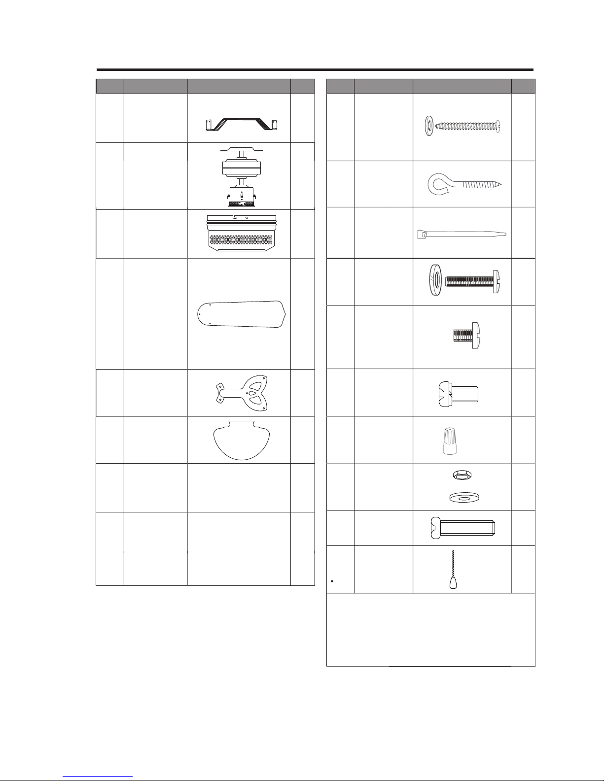
Part
Description
Illustration
QTY
Part
Description
Illustration
QTY
1,5,
12
Mounting
bracket
Fan motor
assembly
11
Motor
housing
Blade
15
16
20
Blade
bracket
Glass shade
4
1
1
1
4
1
2,3
2,3
_
_
_
_
ST4.8 x 38
Wood screw
with flat
washer
2
1
2
13
1
3
13
2
“J” hook
Sm4 X 25
Outlet box
screw with
lock washer
14
13
M5 X 12
blade screw
Wire
connector
Above parts listed in the right column are
packed in hardware bag. (Hardware not
shown to actual size.)
Notes:
G1/4” X 8
Extra blade
bracket
screw with
split washer
Pull chain
with fob
Hexagon nut
with flat
washer
4,5,6,
7,8,9,
10,17,
18,19
1
Zip tie
_
_
1
Extra light
kit screw
4
PARTS LIST
QTY
1
2
2
1
3
1
1
1
1
1
1
4
12
12
4
4
8
1
3
1
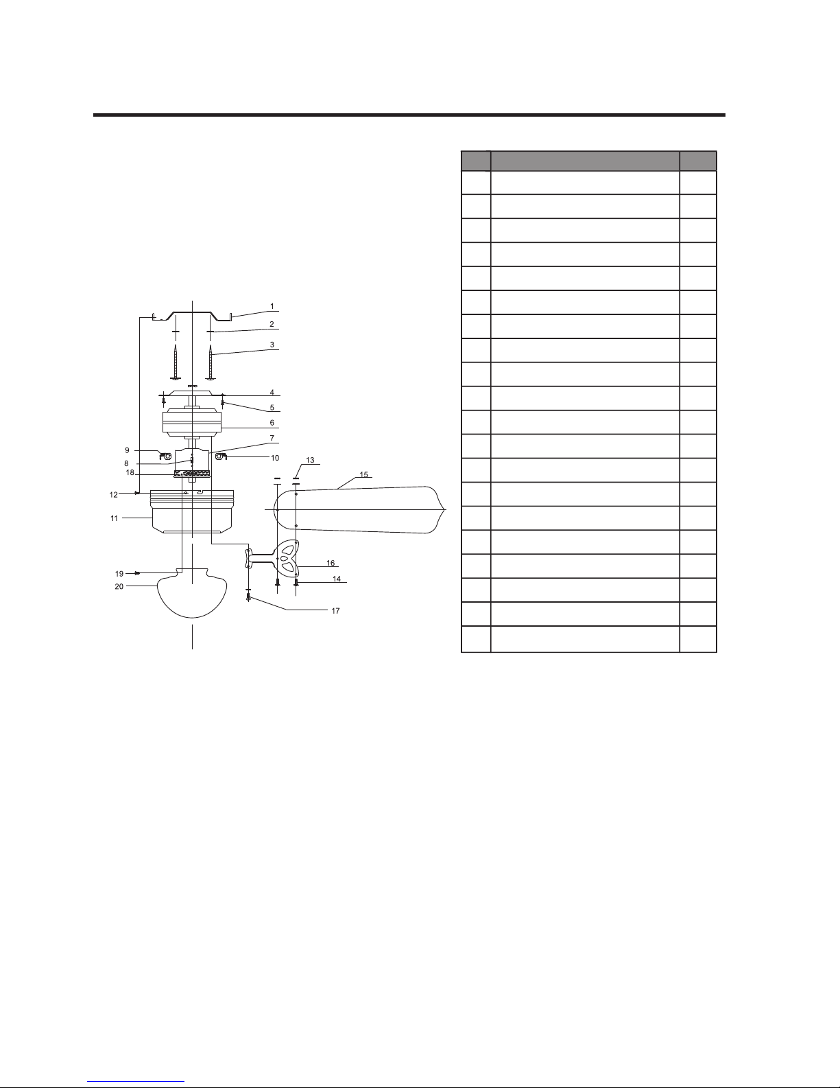
NO.
Description
1
2
3
4
5
6
7
8
9
10
11
12
13
14
15
16
17
18
19
20
3
L
2
1
3
L
2
1
Mounting Bracket
Lock Washer
Wood Screw/ Outlet Box Screw
Motor Support Bar
Mounting Screw
Motor
Switch Housing
Reverse Switch
Fan Pull Chain
Light Pull Chain
Motor Housing
Motor Housing Screw
Hexagon Nut
Blade Screw
Blade
Blade Bracket
Blade Bracket Screw
Light Kit
Light Kit Screw
Glass Shade
Flat Washer/
5
PARTS LOCATIONS
 Loading...