

Page 1
User's guide
XAC80 PB
ATEX certification category 3
for use in zones 2, 22
and temperature class T5 (T100°C)
• 18-bit singleturn encoder for high precision demands
• 27-bit multiturn encoder for standard purposes
• 30-bit multiturn encoder for high end applications
• Profibus DP configurable as Class 1, Class 2 or Class 2(+VEL) Slave
• Heavy-duty construction for harsh environments
Suitable for the following models:
• XAC8018/1PB
• XAC8013/16384PB
• XAC8016/16384PB
General Contents
1 - Safety summary 17
2 - Identification 19
3 – Certificates 20
4 - Mounting instructions 25
5 - Electrical connections 27
6 - Quick reference 32
7 - Profibus® interface 39
8 - Default parameters list 57
Lika Electronic • Tel. +39 0445 806600 • info@lika.biz • www.lika.biz
Smart encoders & actuators
II 3GD, Ex nA IIB T5 Gc
II 3GD, Ex tc IIIC T100°C Dc, IP65
Profibus-DP profile for encoders
Page 2

This publication was produced by Lika Electronic s.r.l. 2018. All rights reserved. Tutti i diritti riservati. Alle Rechte vorbehalten. Todos los
derechos reservados. Tous droits réservés.
This document and information contained herein are the property of Lika Electronic s.r.l. and shall not be reproduced in whole or in
part without prior written approval of Lika Electronic s.r.l. Translation, reproduction and total or partial modification (photostat copies,
film and microfilm included and any other means) are forbidden without written authorisation of Lika Electronic s.r.l.
The information herein is subject to change without notice and should not be construed as a commitment by Lika Electronic s.r.l. Lika
Electronic s.r.l. reserves the right to make all modifications at any moments and without forewarning.
This manual is periodically reviewed and revised. As required we suggest checking if a new or updated edition of this document is
available at Lika Electronic s.r.l.'s website. Lika Electronic s.r.l. assumes no responsibility for any errors or omissions in this document.
Critical evaluation of this manual by the user is welcomed. Your comments assist us in preparation of future documentation, in order
to make it as clear and complete as possible. Please send an e-mail to the following address info@lika.it for submitting your
comments, suggestions and criticisms.
Page 3

Table of Contents
User's guide......................................................................................................................................................... 1
Table of Contents............................................................................................................................................ 3
Subject Index................................................................................................................................................... 5
Typographic and iconographic conventions.............................................................................................6
Preliminary information................................................................................................................................ 7
Glossary of Profibus terms........................................................................................................................... 8
1 - Safety summary..................................................................................................................................... 17
1.1 Safety........................................................................................................................................................................................17
1.2 Electrical safety....................................................................................................................................................................17
1.3 Mechanical safety...............................................................................................................................................................18
1.4 Operational safety...............................................................................................................................................................18
2 - Identification.......................................................................................................................................... 19
3 – Certificates............................................................................................................................................. 20
3.1 Declaration of ATEX Conformity...................................................................................................................................20
3.2 EU Declaration of Conformity.......................................................................................................................................22
3.3 Safety instructions..............................................................................................................................................................23
4 - Mounting instructions......................................................................................................................... 25
4.1 Encumbrance sizes..............................................................................................................................................................25
4.2 Mounting the encoder......................................................................................................................................................26
5 - Electrical connections........................................................................................................................... 27
5.1 Connection cap....................................................................................................................................................................27
5.2 Connection cap with PG gland (cable output).......................................................................................................28
5.3 Ground connection............................................................................................................................................................28
5.3.1 Connection of the shield.........................................................................................................................................29
5.4 Setting the node number: DIP A (Figure 2)..............................................................................................................29
5.5 Baud rate................................................................................................................................................................................ 30
5.6 Bus termination resistance (Figure 2)........................................................................................................................31
6 - Quick reference...................................................................................................................................... 32
6.1 STEP7 configuration...........................................................................................................................................................32
6.1.1 Importing the GSD file..............................................................................................................................................32
6.1.2 Adding a node to the project.................................................................................................................................33
6.1.3 Encoder configuration parameters.....................................................................................................................34
6.2 Reading the diagnostic information...........................................................................................................................35
6.3 Setting the Preset value...................................................................................................................................................37
7 - Profibus® interface................................................................................................................................ 39
7.1 GSD file....................................................................................................................................................................................39
7.2 Classes of the Device profile...........................................................................................................................................39
7.3 Modes of operation............................................................................................................................................................40
7.3.1 Types of communication..........................................................................................................................................40
7.4 DDLM_Set_Prm....................................................................................................................................................................41
7.4.1 Byte 10 - Operating parameters...........................................................................................................................43
Code sequence..................................................................................................................................................................43
Class 2 functionality.....................................................................................................................................................43
Scaling function control.............................................................................................................................................44
Exchange type...................................................................................................................................................................44
7.4.2 Bytes 11 … 14...............................................................................................................................................................45
Page 4

Counts per revolution..................................................................................................................................................45
7.4.3 Bytes 15 … 18...............................................................................................................................................................46
Total resolution................................................................................................................................................................46
7.4.4 Byte 19.............................................................................................................................................................................48
Velocity measure unit..................................................................................................................................................48
7.5 DDLM_Chk_Cfg....................................................................................................................................................................49
7.6 DDLM_Data_Exchange.....................................................................................................................................................49
Position value....................................................................................................................................................................49
Position and velocity values.....................................................................................................................................50
Preset value........................................................................................................................................................................50
7.7 DDLM_Slave_Diag..............................................................................................................................................................52
Station_Status_1..........................................................................................................................................................52
Station_Status_2..........................................................................................................................................................53
Station_Status_3..........................................................................................................................................................53
Master_Add.....................................................................................................................................................................53
Ident_Number................................................................................................................................................................53
Extended diagnostic header.....................................................................................................................................53
Alarms................................................................................................................................................................................53
Operating status............................................................................................................................................................54
Encoder type...................................................................................................................................................................54
Singleturn resolution...................................................................................................................................................54
Number of distinguishable revolutions...............................................................................................................54
7.8 "Dead Zone"...........................................................................................................................................................................55
8 - Default parameters list........................................................................................................................ 57
Page 5

Subject Index
A
Alarms...................................................................................53
C
Class 2 functionality.......................................................43
Code sequence..................................................................43
Counts per revolution....................................................45
E
Encoder type......................................................................54
Exchange type...................................................................44
Extended diagnostic header........................................53
I
Ident_Number...................................................................53
M
Master_Add........................................................................53
N
Number of distinguishable revolutions..................54
O
Operating status...............................................................54
P
Position and velocity values........................................50
Position value....................................................................49
Preset value........................................................................50
S
Scaling function control...............................................44
Singleturn resolution......................................................54
Station_Status_1.............................................................52
Station_Status_2.............................................................53
Station_Status_3.............................................................53
T
Total resolution.................................................................46
V
Velocity measure unit....................................................48
Page 6
Typographic and iconographic conventions
In this guide, to make it easier to understand and read the text the following typographic and
iconographic conventions are used:
• parameters and objects of both Lika device and interface are coloured in GREEN;
• alarms are coloured in RED;
• states are coloured in FUCSIA.
When scrolling through the text some icons can be found on the side of the page: they are expressly
designed to highlight the parts of the text which are of great interest and significance for the user.
Sometimes they are used to warn against dangers or potential sources of danger arising from the use of
the device. You are advised to follow strictly the instructions given in this guide in order to guarantee
the safety of the user and ensure the performance of the device. In this guide the following symbols are
used:
This icon, followed by the word WARNING, is meant to highlight the parts of the
text where information of great significance for the user can be found: user must
pay the greatest attention to them! Instructions must be followed strictly in order
to guarantee the safety of the user and a correct use of the device. Failure to heed
a warning or comply with instructions could lead to personal injury and/or damage
to the unit or other equipment.
This icon, followed by the word NOTE, is meant to highlight the parts of the text
where important notes needful for a correct and reliable use of the device can be
found. User must pay attention to them! Failure to comply with instructions could
cause the equipment to be set wrongly: hence a faulty and improper working of
the device could be the consequence.
This icon is meant to highlight the parts of the text where suggestions useful for
making it easier to set the device and optimize performance and reliability can be
found. Sometimes this symbol is followed by the word EXAMPLE when instructions
for setting parameters are accompanied by examples to clarify the explanation.
Page 7

Preliminary information
This guide is designed to provide the most complete information the operator needs to correctly and
safely install and operate the following encoders fitted with Profibus interface:
XAC8018/1PB-xx (18 bit singleturn encoder)
XAC8013/16384PB-xx (13 +14 bit multiturn encoder)
XAC8016/16384PB-xx (16 +14 bit multiturn encoder)
For technical specifications please refer to the product datasheet.
To make it easier to read the text, this guide can be divided into some main sections.
In the first section (from chapter 1 to chapter 4) general information concerning the safety, the
mechanical installation and the electrical connection.
In the second section (chapter 5) information on how to install and configure the encoder under the
Siemens STEP7 development environment as well as tips for setting up and running properly and
efficiently the unit are provided.
In the third section (chapters 6 and 7) both general and specific information is given on the Profibus
interface. In this section the interface features and the parameters implemented in the unit are fully
described.
Page 8

Glossary of Profibus terms
Profibus, like many other networking systems, has a set of unique terminology. Table below contains a
few of the technical terms used in this guide to describe the Profibus interface. They are listed in
alphabetical order.
Address (Station)
IEC 61158-2: Medium attachment unit identification - unique
number of a station connected to a segment (participant).
Address Space
Within PROFIBUS DP the maximum possible number of
addressable network nodes per segment, e.g. 127.
Alarm
Notification of an abnormal or unexpected event within a
system. Alarms in PROFIBUS DP require in addition to the
standard diagnosis event mechanism within the cyclic data
exchange a separate acyclic acknowledgement procedure
between a host and a Slave application. Since DP-V1, "Device
related diagnosis" is the basis for the "Alarm" and "Status"
types of diagnosis events (GSD: "DPV1"=1). PROFIBUS DP
defines the following alarm types: Diagnosis, Status, Process,
Update, Pull and Plug Alarm. See "Device Related Diagnosis".
The PNO maintains a Profile Guideline, Part3: Diagnosis,
Alarms and Time Stamping, order no. 3.522.
Alert
Alert is a generic term for two different types of notifications
within a PROFIBUS DP/PA network especially arranged but not
exclusively for the process automation:
• alarm;
• event.
Both alert types may be used with or without a user
acknowledgement mechanism. The PNO maintains a PROFIBUS
guideline "Time Stamp", order no. 2.192.
Application Profile
Within PROFIBUS a specified agreement within families of
field devices on how to use the general PROFIBUS
communication platform and its subsystems (e.g. device
integration via GSD, EDD, FDT/DTM and Communication
Function Blocks). Communication profiles are not a part of the
PROFIBUS DP application profiles. See "Profile".
Baud rate (Data Rate)
Other common terms are "data transfer rate" and
"transmission rate". Within PROFIBUS DP this is the amount of
data transferred across a fieldbus segment per second. A data
rate is measured in units of bits per second ( "b/s" or "bps"), or
baud.
Bus Cycle
The period of time the bus Master needs to poll every
participant (Slave) once. More bus Masters can be activated by
using the token principle which consequently prolong the bus
cycle.
Page 9

Class
See “DP Master”, “DP Master Class 1 (DPM1)” and “DP Master
Class 2 (DPM2)”.
Class 1 encoder
Encoder class must be set when you configure the device.
Mandatory Class 1 provides the basic functions of the device
and can be used for:
• sending the position value (see Position value
parameter);
• changing the counting direction (see Code sequence
parameter);
• setting the preset value (see Preset value parameter);
• acquiring reduced diagnostic information (see
Diagnostic type parameter = “16 bytes fixed (6+10)”).
Class 2 (+VEL) encoder
Encoder class must be set when you configure the device.
Class 2 (+VEL) provides all the Class 1 and Class 2 functions
and additional velocity-related functions:
• transmission of the velocity value (see Position and
velocity values parameter);
• setting of the velocity measuring unit (see Velocity
measure unit parameter).
Class 2 encoder
Encoder class must be set when you configure the device.
Class 2 provides all the Class 1 functions and additional
advanced functions such as:
• scaling function (see Scaling function control,
Counts per revolution and Total resolution
parameters);
• extended diagnostic information (see Diagnostic type
parameter = “16 bytes (6+10)” or “63 bytes (6+57)”).
Communication Function
Block (Comm FB)
A basic function block defined for PROFIBUS DP and supplied
by the PLC manufacturer for the standardized access of user
programs to field devices. The standardization is based on IEC
61131-3. The PNO maintains a guideline "PROFIBUS
Communication and Proxy Function Blocks acc. to IEC 611313", order no. 2.182.
Communication
Parameter
Communication parameters are parameters, which adjust the
communication protocol function to the current net
configuration. Communication parameters exist for all phases
of the communication protocols. Examples are bus address,
token rotation time, idle time. See "Slave parametrization" and
"Device parametrization".
Communication Profile
IEC 61158 comprises a summary of layer stacks of several
different fieldbusses. IEC 61784 defines the useful
combinations of these stacks via communication profiles
CPF3/1 up to CPF3/3 (PROFINET). One of these is PROFIBUS DP.
Within this communication profile three different physical
profiles are defined:
• RS 485 (RS 485-IS);
• MBP-IS (MBP-LP, MBP);
Page 10

• Fibre Optics.
Cyclic Data Exchange
IEC 61158-3: Term used to describe events which repeat in a
regular and repetitive manner. The MS0 services of PROFIBUS
DP are based on cyclic data exchange. See "State machine".
Cyclic Redundancy Check
(CRC)
Error-checking technique in which the frame recipient
calculates a remainder by dividing frame contents by a prime
binary divisor and compares the calculated remainder to a
value stored in the frame by the sending node.
Data Rate (Baud rate)
Other common terms are "data transfer rate" and
"transmission rate". Within PROFIBUS DP this is the amount of
data transferred across a fieldbus segment per second. A data
rate is measured in units of bits per second ("b/s" or "bps"), or
baud.
Decentralized Peripherals
(DP)
The term "Decentralized Peripherals" and the acronym "DP"
stand for the simple, fast, cyclic and deterministic I/O data
exchange between a bus Master and its assigned Slave devices.
The corresponding PROFIBUS communication protocol is
called PROFIBUS DP.
Device Identifier
Ident number: The primary device identification is an ident
number of data type Unsigned16. This number is unique and
assigned by the PNO business office upon application. It is
stored within the device and defined in the corresponding
GSD file via keyword. In addition it is part of the GSD file
name. At runtime the ident number is used within:
• the set Slave address procedure;
• the parametrization telegram (octet 5 + 6);
• the standard part of a diagnosis message (octet 5 + 6).
The ident number explicitly cannot be retrieved from a device.
Its main purpose is to make sure that a GSD file and
configuration/parametrization data between Master Class 1
and its Slave are matching. The PNO maintains a technical
guideline "Specification for PROFIBUS device description and
device integration, Volume 1: GSD", Version 5.0, order no.
2.122. For a secondary identification possibility see the
identification & maintenance functions (I&M). See "Ident
Number".
Device Parametrization
The device parametrization within PROFIBUS DP consists of
three phases. The first phase takes place during start-up of the
communication system and provides basic communication
parametrization and simple additional device parameters. Both
are defined within the GSD file of a device, stored within a
Master Class 1 after configuration in an engineering tool, and
transmitted to the Slave at start-up time. Most of the
automation cases in factory automation are covered by this
method. More complex devices such as drives, laser scanners,
scales, robots, transmitters, etc. require further individual
parametrization before final production start. This is done in a
second phase. In process automation certain device
Page 11

parameters such as value limits, value range, gain, etc. need to
be adjusted even at run-time. For this second and third phase
PROFIBUS DP provides two ways to accomplish the task:
DTM/FDT and EDD. See "Slave parametrization" and
"Communication parameter".
Device Profile
See "Profile".
DP Master
IEC 61158-5: Within PROFIBUS DP a fieldbus node that can be
either Master Class 1 or Master Class 2. A Master Class 1 is a
controlling device which controls several DP Slaves (field
devices). NOTE: This is usually hosted by a programmable
controller or a process controller.
A Master Class 2 is a controlling device which manages
configuration data (parameter sets) and diagnosis data of a DP
Master Class 1, and that additionally can perform all
communication capabilities of a DP Master Class 1.
DP Master Class1 (DPM1)
IEC 61158-5: A controlling device which controls several DPSlaves (field devices). Usually programmable (logic) controllers
or process control systems are hosts for Master Class 1.
DP Master Class2 (DPM2)
IEC 61158-5: A controlling device which manages
configuration data (parameter sets) and diagnosis data of a
DP-Master (Class 1). Additionally the DP-Master (Class 2) can
perform all communication capabilities of a DP-Master (Class
1). Usually personal computers are hosts for DP Master Class 2
for programming, parametrizing, diagnosing and monitoring
purposes.
DP Slave
IEC 61158-5: A field device that is assigned to one DP Master
Class 1 as a provider for cyclic I/O data exchange. In addition
acyclic functions and alarms could be supported.
Event
Within PROFIBUS DP/PA this is a signal or I/O data or process
value within a certain field device at that point in time where
a trigger condition arises. The values are associated with a
time stamp and stored in a buffer. The time-stamped sample
values are used to archive and visualize significant changes
over the course of the production process. Such an event
mechanism does not prevent from the cyclic transmission of
these signals. A separate event alarm is requesting the transfer
of the events to the main system.
Frame
A single set of data transmission from a device.
General Station
Description (GSD)
A GSD is an electronically readable ASCII text file and contains
both general and device-specific parameters for
communication and network configuration. By means of
keywords, a configuration tool allows to:
• read device information (manufacturer, type, versions,
bitmaps, etc.);
• read texts for comfortable and easy to use
configuration;
• select transmission rates;
Page 12

• select modules and their I/O data length
(configuration identifier);
• read texts to assign diagnosis IDs to HMI displays;
• select supported services (freeze, sync, etc.);
from the GSD for the configuration of the device. A GSD
replaces the previously conventional manuals or data sheets
and thus already supports plausibility checks during the
configuration phase. Distinction is made between a device
GSD (for an individual device only) and a profile GSD, which
may be used for devices that comply exactly with a profile
such as a "PA device". GSDs for different languages may be
provided in separate files with corresponding file extensions
(*.gse for English, *.gsg for German, etc.) or altogether in one
file (*.gsd). The device manufacturers are responsible for the
scope and quality of the GSD of their devices.
Ident Number
See "Device Identifier".
Notes:
• the ident number is necessary for all DP devices except
for Master Class 2;
• the same ident number may be used for modular
devices as long as the device can be described in the
GSD file as a modular device.
Identifier
In general: a symbol that establishes the identity of the one
bearing it. Within this context here it represents an absolute
value of a parameter such as a physical address. It is intended
for systematic and performance handling capabilities within
computer systems, e.g. sorting, consistency checking, physical
localization and alike. Usually an absolute value is associated
with a logical value to represent the particular deployment of
the identifier. Typical abbreviation for identifier is ID.
IEC 61131-3: A combination of letters, numbers and underline
characters, which begins with a letter or underline and which
names a language element. Some of the major identifiers
within PROFIBUS DP are:
- Data type numeric identifier;
- Configuration identifier (Cfg);
- Device identifier (ident number);
- Manufacturer identifier (MANUFACTURER ID);
- Profile ident number (PROFILE ID).
Index
IEC 61158-5: Address of an object within an application
process.
The permitted range in PROFIBUS DP is 0 - 255. Indexes are
used to address records of data (parameters, variables, state
information, commands, etc.) within modules of a field device.
PDU (Protocol Data Unit)
A packet of data passed across a network via telegrams. The
term implies a specific layer of the OSI seven layer model and
a specific protocol. Each layer has its own PDU that is
extended subsequently from the physical layer up to the
application layer:
Page 13

• Physical layer protocol data unit (PhPDU);
• Data link protocol data unit (DLPDU);
• Application protocol data unit (APDU).
PI
The
PROFIBUS Nutzerorganisation e.V.
(PROFIBUS User
Organisation, or PNO) was created in 1989. This group was
composed mainly of manufacturers and users from Europe. In
1992, the first regional PROFIBUS organization was founded
(PROFIBUS Schweiz in Switzerland). In the following years,
additional Regional PROFIBUS & PROFINET Associations (RPAs)
were added. In 1995, all the RPAs joined together under the
international umbrella association PROFIBUS & PROFINET
International (PI). Today, PROFIBUS is represented by 25 RPAs
around the world (including PNO) with over 1400 members,
including most if not all major automation vendors and
service suppliers, along with many end users.
PNO
The
PROFIBUS Nutzerorganisation e.V.
(PROFIBUS User
Organisation, or PNO) was created in 1989. This group was
composed mainly of manufacturers and users from Europe. In
1992, the first regional PROFIBUS organization was founded
(PROFIBUS Schweiz in Switzerland). In the following years,
additional Regional PROFIBUS & PROFINET Associations (RPAs)
were added. In 1995, all the RPAs joined together under the
international umbrella association PROFIBUS & PROFINET
International (PI). Today, PROFIBUS is represented by 25 RPAs
around the world (including PNO) with over 1400 members,
including most if not all major automation vendors and
service suppliers, along with many end users.
PROFIBUS
PROcess FIeldBUS. PROFIBUS is a manufacturer independent
fieldbus standard for applications in manufacturing, process
and building automation. The PROFIBUS family is composed of
three types of protocol, each of which is used for different
tasks. The three types of protocols are: PROFIBUS FMS, DP and
PA.
IEC 61784-1: Communication network according to
communication profile family 3 (CPF3); incorporating
application profiles and system integration aspects like
interfaces and languages for engineering tools and HMI.
PROFIBUS is an open, digital communication system with a
wide range of applications, particularly in the fields of factory
and process automation. PROFIBUS is suitable for both fast,
time-critical applications and complex communication tasks.
The PROFIBUS logo is a registered trademark.
PROFIBUS DP
Acronym for "PROFIBUS for Decentralized Peripherals".
Specification of an open fieldbus system with the following
characteristics:
• polling Master-Slave-system (cyclic communications,
MS0);
• flying Masters with robin round token passing
coordination (MM);
Page 14

• connection based (MS1) and connectionless (MS2,
MS3) acyclic communication between Masters and
Slaves.
Options (e.g.):
• Data exchange broadcast (DXB), i.e. Slave to Slaves
communication;
• isochronous mode of Slaves;
• clock synchronization;
• redundancy.
PROFIBUS DP is standardized within IEC 61158 and IEC 61784,
communication profile families 3/1 and 3/2. The term
"PROFIBUS DP" is also a synonym for the RS-485 based
deployments within factory automation.
PROFIdrive
Communication technology especially adopted to the
requirements of position and speed controlled drive
applications (e.g. speed synchronized axis). Within the scope of
PROFIBUS, "PROFIdrive" is used for the application of the
PROFIBUS DP protocol (DP-V2) in motion control automation
together with the corresponding application profiles
("PROFIdrive - Profile for variable speed drives" and
"PROFIdrive - Profile drive technology") for the transmission
technology RS-485.
Profile
Besides other things profiles in common define agreements on
how to use communication means in a standardized manner.
Within the context of fieldbusses several types of profiles are
known:
• communication profiles (e.g. IEC 61784);
• physical profiles (MBP-IS, RS-485);
• application profiles (see PROFIBUS TC3);
• device profiles (e.g. robots);
• branch profiles (e.g. extruder).
Profile Ident Number
Identifier of a particular profile definition. The profile ident
number is taken from the pool of ident numbers handled by
the PNO. It plays a role within the following scenarios.
(1) In cases where the device of a manufacturer A should be
replaceable by an equivalent device, the PNO is assigning
number ranges to dedicated device types (Profile specific IDs)
in combination with certain "Profile GSDs". Profiles using this
methodology are e.g. "PA Devices" and "PROFIdrive".
(2) Usually these Slave devices are designed to communicate
with a Master Class 2 application (e.g. profile application or
profile DTM). In order to ensure a Master application is
communicating with an appropriate Slave, it is sending a
profile specific ID during the establishment of the connection
(MS2 Initiate Service). The Slave may answer with the same
profile specific ID (if it is supporting this profile), with another
ID (if it is supporting another profile) or with "0000h" if it is
not supporting any profile.
(3) I&M functions: Besides its basic I&M information devices -
Page 15

following a certain profile - are enabled to provide more
detailed profile specific information.
Protocol Data Unit (PDU)
A packet of data passed across a network via telegrams. The
term implies a specific layer of the OSI seven layer model and
a specific protocol. Each layer has its own PDU that is
extended subsequently from the physical layer up to the
application layer:
• Physical layer protocol data unit (PhPDU);
• Data link protocol data unit (DLPDU);
• Application protocol data unit (APDU).
Slave Parametrization
For a DP Slave several levels of parametrization exist.
(1) The parameters on the DP communication level can be
defined via a GSD file and comprise features such as baud
rates, timing constraints, identification, options, transferable
data structures, publisher subscriber links, etc. This level
supports parametrization of simple modular Slaves and also
special common additional communication layers such as
PROFIsafe. This parametrization is fixed for a given operational
life cycle after start-up.
(2) More complex devices may be parametrized via EDD and/or
FDT/DTM technology via an acyclic communication service
(MS2).
(3) For parameter changes at run-time such as batch
operation (recipes) or motion control, special "parameter
channels" associated with the cyclic data structures may be
added or the MS1 services together with proxy function blocks
may be used.
State Machine (DP)
An abstract machine consisting of a set of states (including
the initial state), a set of input events, a set of output events,
and a state transition function. A state machine describes the
behaviour of a field device how to react in different situations.
The state machine for DP Slaves comprises the following
states/actions:
- Power_On_Reset --> Set Slave address --> if successful, a
transition follows to:
- Wait_Prm --> Parametrization, diagnosis (optional) --> if
successful, a transition follows to:
- Wait_Cfg --> Configuration, diagnosis (optional) --> if
successful, a transition follows to:
- Data_Exch --> Normal operation: cyclic data exchange.
On top of this basic communication layer state machine
application profiles are defining their own additional state
machines, e.g. PA devices, PROFIdrive, PROFIsafe, Ident
Systems, Weighing and Dosage Systems.
State machines are best modelled and documented with the
help of the "Unified Modelling Language (UML)".
Station Address
Within PROFIBUS DP the address of a communication
participant (Master or Slave). The permitted range is 0 to 127,
with:
Page 16

- 126 intended to be used for the "soft" addressing of Slave
devices;
- 127 intended to be used for broadcast messages to all the
Slaves.
Topology
In a communication network, the pattern of interconnection
between network nodes; e.g. bus, ring, star configuration.
Transmission Rate (Baud
rate)
The signalling rate of a digital communication line. It is the
switching speed, or number of transitions (voltage or
frequency changes) that are made per second. Within
PROFIBUS DP the possible transmission rates depend on the
MAU (Medium Attachment Unit) in use.
Watchdog Control
IEC 61158-6: This timer is part of the DP layer within a Slave.
It is restarted by received requests from the bus Master and
will set the outputs of a Slave to a fail-safe state after the
expiration of the timer.
Watchdog Time (Twd)
IEC 61158-5: The watchdog timer is part of the DP layer
within a Slave. The watchdog time is set by parametrization at
run-up and consists of a watchdog time base (1 or 10 ms) and
2 factors. A selection can be made during configuration via
the GSD file of a Slave. This is a Slave parameter. See
"Watchdog control".
Page 17
XAC80 Profibus-DP
®
1 - Safety summary
1.1 Safety
Always adhere to the professional safety and accident prevention regulations
applicable to your country during device installation and operation;
installation and maintenance operations have to be carried out by qualified
personnel only, with power supply disconnected and stationary mechanical
parts;
device must be used only for the purpose appropriate to its design: use for
purposes other than those for which it has been designed could result in
serious personal and/or the environment damage;
high current, voltage and moving mechanical parts can cause serious or fatal
injury;
failure to comply with these precautions or with specific warnings elsewhere
in this manual violates safety standards of design, manufacture, and
intended use of the equipment;
Lika Electronic assumes no liability for the customer's failure to comply with
these requirements.
1.2 Electrical safety
Turn off power supply before connecting the device;
connect according to explanation in the “5 - Electrical connections” section
on page 27;
in compliance with the 2014/30/EU norm on electromagnetic
compatibility, following precautions must be taken:
- before handling and installing, discharge electrical charge from
your body and tools which may come in touch with the device;
- power supply must be stabilized without noise, install EMC filters on device
power supply if needed;
- always use shielded cables (twisted pair cables whenever possible);
- avoid cables runs longer than necessary;
- avoid running the signal cable near high voltage power cables;
- mount the device as far as possible from any capacitive or inductive noise
source, shield the device from noise source if needed;
- to guarantee a correct working of the device, avoid using strong magnets on
or near by the unit;
- minimize noise by connecting the shield and/or the frame to ground. Make
sure that ground is not affected by noise. The connection point to ground
can be situated both on the device side and on user’s side. The best solution
to minimize the interference must be carried out by the user. Provide the
ground connection as close as possible to the encoder. We suggest using the
ground screw provided in the cap (see Figure 1);
the rated supply voltage must not exceed 30Vdc;
in classified areas the electrical connection of the device must be carried out
in compliance with the methods stated in the EN 60079-0 regulation;
MAN XAC80 PB E 1.0.odt 1 - Safety summary 17 of 60
Page 18

XAC80 Profibus-DP
®
the user has to take suitable measures in order to prevent longer or
continuous disturbances that cause the supply voltage to exceed by 10% or
more;
the product must be protected against overheating due to mechanical or
electrical overloading.
1.3 Mechanical safety
Install the device following strictly the information in the section “4 -
Mounting instructions”;
mechanical installation has to be carried out with stationary mechanical
parts;
do not disassemble the encoder;
do not tool the encoder or its shaft;
delicate electronic equipment: handle with care; do not subject the device
and the shaft to knocks or shocks;
respect the environmental characteristics declared by manufacturer.
1.4 Operational safety
The described products are category 3 certified and are designed for use in
potentially explosive zones 2 (according to EN60079-15) and 22 (according
to EN60079-31). They are suitable for a safe use and a normal level of
protection in areas in which explosive atmospheres caused by mixture of
gases and vapors (zone 2) or dust (zone 22) are unlikely to occur and if they
do occur do so for a short period of time. They comply with the
constructional safety requirements of the temperature class T5 (T100°C =
+212°F). They are not to be used in Zones 0, 1, 20 and 21;
protection requirements: Zone 2, gas explosion protection (G): protection by
non sparking equipment: the construction minimizes the occurrence of
sparks, arcs or hot surfaces, which in normal operation might give the risk of
explosion; Zone 22, dust explosion protection (D): the construction of the
product protects against the penetration of dust in hazardous quantities
(min. IP5x) and guarantees that the surface temperature is under the ignition
temperature of dust/air mixture as well as under the smoldering temperature
of dust deposits;
the manufacturer's specifications (temperature, speed, …) must under no
circumstances be exceeded;
max. permissible environmental temperature: -20°C +40°C (-4°F +104°F) at
continuous rotational speed of max. 6000 rpm;
the maximum surface temperature (in °C) of the product must not exceed
2/3 of the ignition temperature of the dust/air mixture;
in continuous operation the plastic parts must be able to withstand a
temperature 10°C higher than the maximum temperature that can be
reached in the hottest point of the product while the environmental
temperature is the highest allowed during operation.
MAN XAC80 PB E 1.0.odt 1 - Safety summary 18 of 60
Page 19

XAC80 Profibus-DP
®
2 - Identification
Device can be identified through the order code and the serial number printed
on the label applied to the enclosure. Information is listed in the delivery
document too. Please always quote the order code and the serial number when
reaching Lika Electronic for purchasing spare parts or needing assistance. For
any information on the technical characteristics of the product refer to the
technical catalogue.
Warning: encoders having order code ending with "/Sxxx" may have
mechanical and electrical characteristics different from standard and
be supplied with additional documentation for special connections
(Technical Info).
MAN XAC80 PB E 1.0.odt 2 - Identification 19 of 60
Page 20

XAC80 Profibus-DP
®
3 – Certificates
3.1 Declaration of ATEX Conformity
MAN XAC80 PB E 1.0.odt 3 – Certificates 20 of 60
Page 21

XAC80 Profibus-DP
®
MAN XAC80 PB E 1.0.odt 3 – Certificates 21 of 60
Page 22

XAC80 Profibus-DP
®
3.2 EU Declaration of Conformity
MAN XAC80 PB E 1.0.odt 3 – Certificates 22 of 60
Page 23

XAC80 Profibus-DP
®
3.3 Safety instructions
MAN XAC80 PB E 1.0.odt 3 – Certificates 23 of 60
Page 24

XAC80 Profibus-DP
®
MAN XAC80 PB E 1.0.odt 3 – Certificates 24 of 60
Page 25

XAC80 Profibus-DP
®
4 - Mounting instructions
WARNING
Installation and maintenance operations must be carried out by qualified
personnel only, with power supply disconnected and mechanical parts
compulsorily in stop.
4.1 Encumbrance sizes
(values are expressed in mm)
MAN XAC80 PB E 1.0.odt 4 - Mounting instructions 25 of 60
Page 26
XAC80 Profibus-DP
®
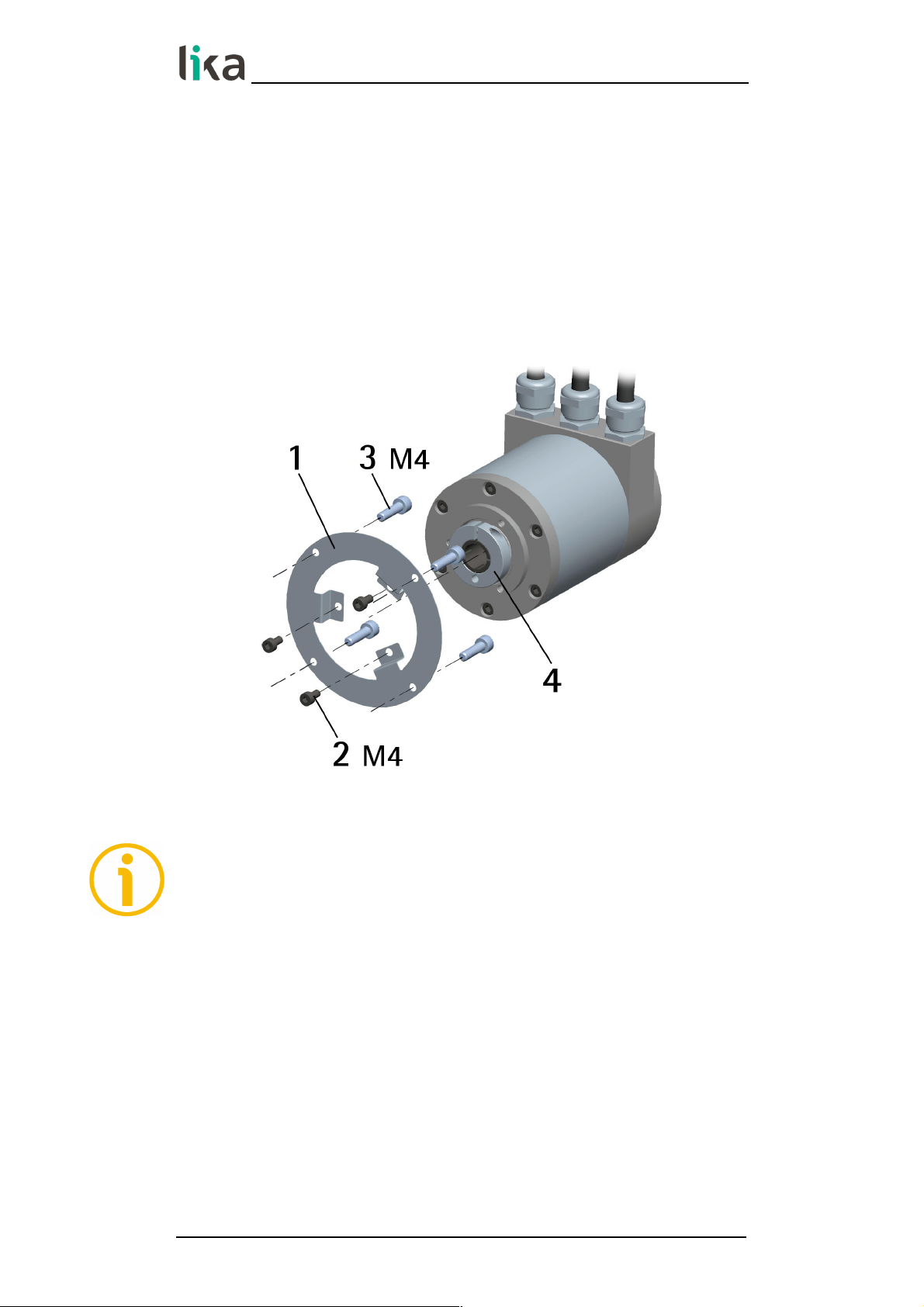
4.2 Mounting the encoder
• Fasten the fixing plate 1 to the encoder using the three M4 screws 2
provided with the device;
• mount the encoder on the motor shaft using the reducing sleeve (if
supplied); avoid forcing the encoder shaft;
• fasten the fixing plate 1 to the rear of the motor using four M4 cylindrical
head screws 3;
• fix the collar 4 to the encoder shaft (apply threadlocker to screw).
NOTE
You are strongly advised not to carry out any mechanical operations (drilling,
milling, etc.) on the encoder shaft. This could cause serious damages to the
internal parts and an immediate warranty loss. Please contact out technical
personnel for the complete availability of custom made shafts.
MAN XAC80 PB E 1.0.odt 4 - Mounting instructions 26 of 60
Page 27
XAC80 Profibus-DP
®
5 - Electrical connections
WARNING
Electrical connections must be carried out by qualified personnel only, with
power supply disconnected and mechanical parts compulsorily in stop.
5.1 Connection cap
WARNING
Do not remove or mount the connection cap with power supply switched ON.
Damage may be caused to internal components.
The terminal connector for connecting the power supply and the BUS IN and
BUS OUT cables as well as the DIP switches meant to set the node ID and
activate the termination resistance are located inside the encoder connection
cap. Thus you must remove the connection cap to access any of them.
NOTE
Be careful not to damage the internal components when you perform this
operation.
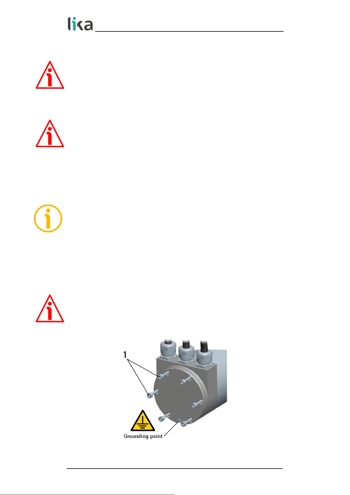
To remove the connection cap loosen the six screws 1. Please be careful with
the internal 15-pin D-SUB connector.
Always replace the connection cap at the end of the operation. Take care in reconnecting the internal 15-pin D-SUB connector. Tighten the screws 1 using a
tightening torque of approx. 2.5 Nm.
WARNING
You are required to check that the encoder body and the connection cap are at
the same potential before replacing the connection cap!
Figure 1 - Removing the connection cap
MAN XAC80 PB E 1.0.odt 5 - Electrical connections 27 of 60
Page 28

XAC80 Profibus-DP
®
5.2 Connection cap with PG gland (cable output)
Figure 2 - Connection cap
The connection cap is fitted with three PG9 cable glands for BUS IN and BUS
OUT connections and power supply connection. The bus cables can be connected
directly to the terminal connectors located in front of each cable gland.
We recommend Profibus-DP certified cables to be used. Core diameter should
not exceed Ø 1.5 mm (0.06 inches). Please note that BUS IN and BUS OUT
connections are actually the same and so interchangeable.
Terminal connector Description
- 0Vdc Supply voltage
+ +10Vdc +30Vdc Supply voltage
B Profibus B (Red)
A Profibus A (Green)
PG
Shield
1
1
Connect the cable shield to cable gland
5.3 Ground connection
Minimize noise by connecting the shield and/or the encoder frame to ground
(GND). Make sure that ground (GND) is not affected by noise. The connection
point to ground can be situated both on the device side and on user's side. The
MAN XAC80 PB E 1.0.odt 5 - Electrical connections 28 of 60
Page 29
XAC80 Profibus-DP
®
best solution to minimize the interference must be carried out by the user. It is
recommended to provide the ground connection as close as possible to the
encoder. We suggest using the ground screw provided in the cap (see Figure 1).
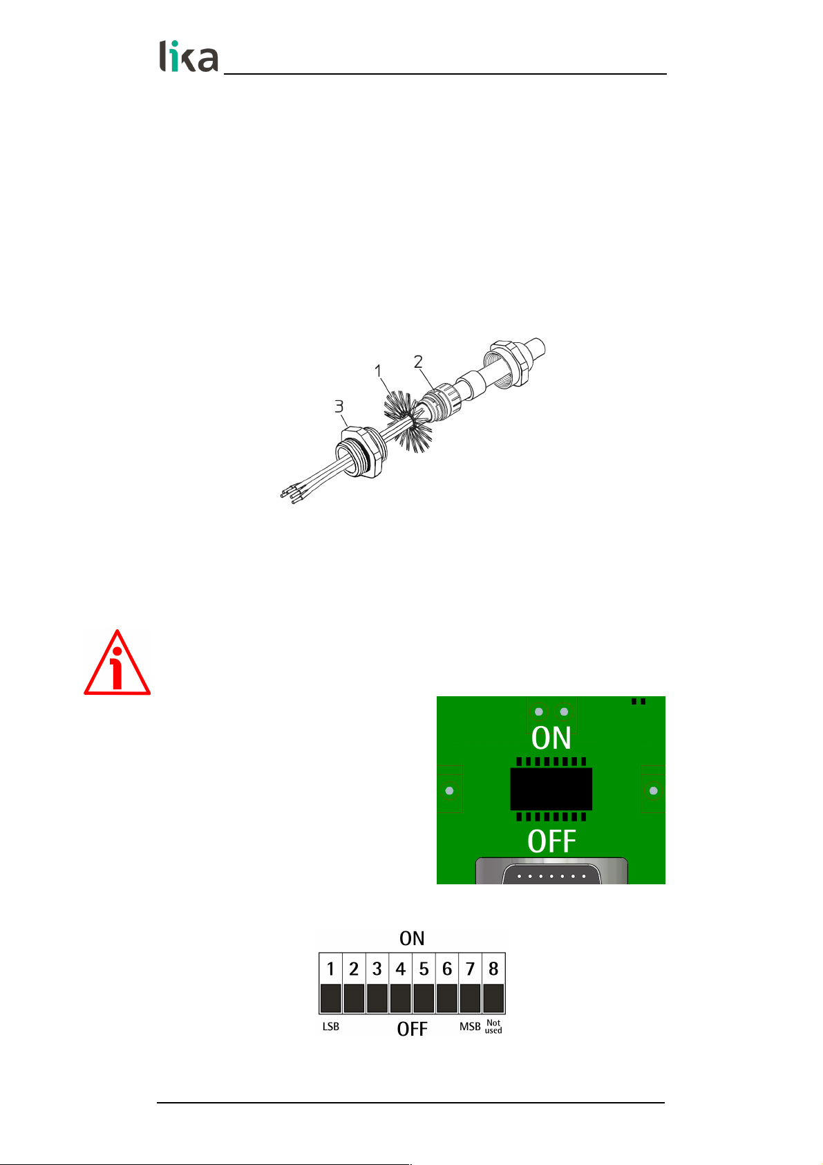
5.3.1 Connection of the shield
Disentangle and shorten the shielding 1 and then bend it over the part 2; finally
place the ring nut 3 of the connector. Be sure that the shielding 1 is in tight
contact with the ring nut 3.
5.4 Setting the node number: DIP A (Figure 2)
WARNING
Power supply must be turned off before performing this operation!
The node number must be set via
hardware using DIP A dip-switches.
Allowed addresses are from 0 to 125. The
default value is 1.
DIP A:
MAN XAC80 PB E 1.0.odt 5 - Electrical connections 29 of 60
Page 30
XAC80 Profibus-DP
®
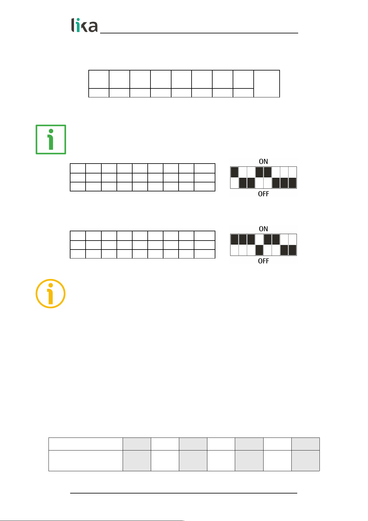
Turn the power supply off and set the node number in binary value; consider
that: ON=1, OFF=0
bit 1
LSB
2 3 4 5 6 7
MSB8not
used
2
0
2
1
2
2
2
3
2
4
2
5
2
6
EXAMPLE
Set node address = 25:
2510 = 0001 10012 (binary value)
bit 1 2 3 4 5 6 7 8
2021222324252
6
ON OFF OFF ON ON OFF OFF OFF
Set node address = 55:
5510 = 0011 01112 (binary value)
bit 1 2 3 4 5 6 7 8
2021222324252
6
ON ON ON OFF ON ON OFF OFF
NOTE
After having set the device address, please check the position of the bus
termination switch (see the “5.6 Bus termination resistance (Figure 2)” section
on page 31).
5.5 Baud rate
The baud rate is set by the Master via software at configuration of the node
(Slave).
The device supports the following baud rates (they are listed in the .GSD file
too):
9.6 kbit/s, 19.2 kbit/s, 93.75 kbit/s, 187.5 kbit/s, 500 kbit/s, 1.5 Mbit/s, 3 Mbit/s, 6
Mbit/s, 12 Mbit/s.
The following table shows the maximum transmission rates in relation to
permissible line length:
Baud rate [Kbit/s]
9.6 19.2 93.75 187.5 500 1,500 12,000
Max. cable length
1200 m
4000 ft
1200 m
4000 ft
1200 m
4000 ft
1000 m
3300 ft
400 m
1300 ft
200 m
660 ft
100 m
330 ft
MAN XAC80 PB E 1.0.odt 5 - Electrical connections 30 of 60
Page 31
XAC80 Profibus-DP
®
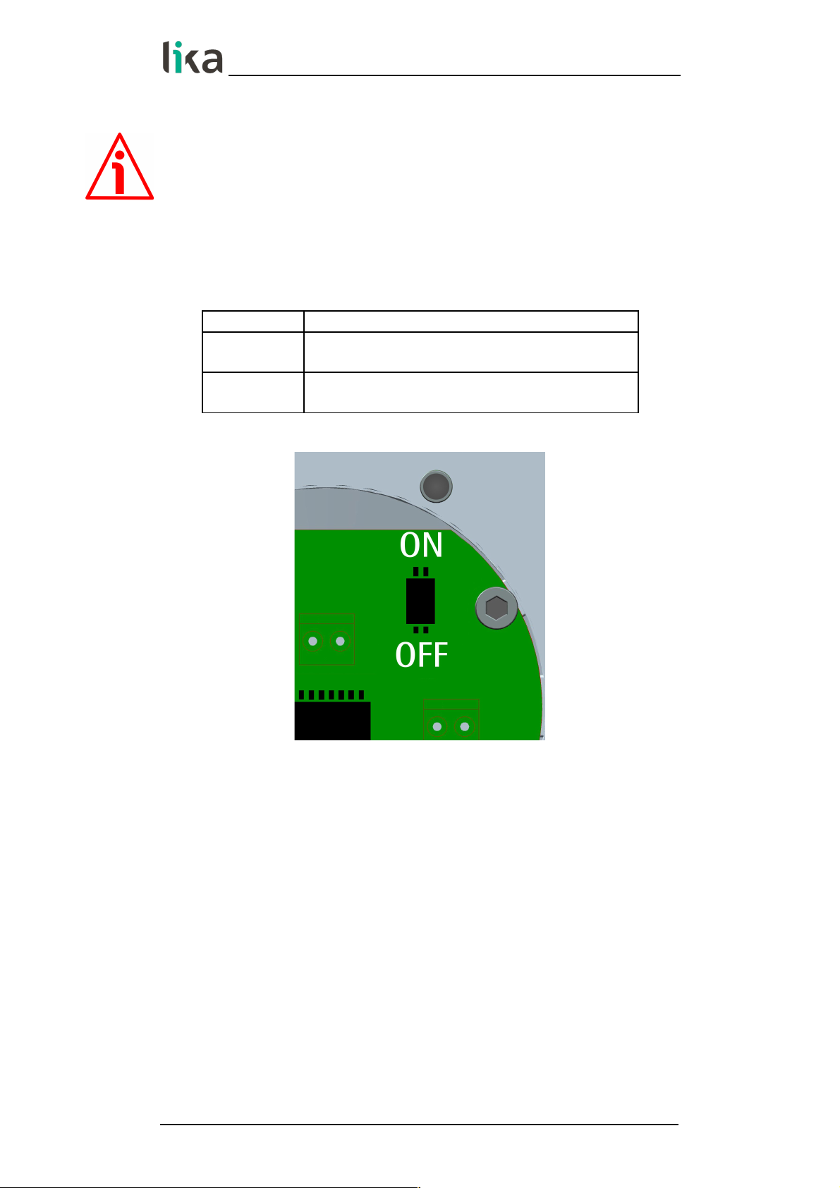
5.6 Bus termination resistance (Figure 2)
WARNING
Power supply must be turned off before performing this operation!
A bus termination resistance is provided inside the connection cap and must be
activated as line termination if the encoder is at the ends of the transmission
line (i.e. it is either the first or the last device in the transmission line).
Use RT Switch to activate or deactivate the bus termination.
RT Description
1 = 2 = ON
Activated: if the encoder is either the first or the
last device in the transmission line
1 = 2 = OFF
Deactivated: if the encoder is not either the first
or the last device in the transmission line
MAN XAC80 PB E 1.0.odt 5 - Electrical connections 31 of 60
Page 32

XAC80 Profibus-DP
®
6 - Quick reference
6.1 STEP7 configuration
6.1.1 Importing the GSD file
Profibus encoders are supplied with their own GSD file, they are specific for
each encoder model. To download the file enter www.lika.biz > ROTARY
ENCODERS > ABSOLUTE ENCODERS > PROFIBUS).
The GSD file must be installed in the Profibus Master device.
The available GSD files are:
xac80_18.GSD: XAC8018/1PB (18 bit singleturn encoder)
xac80_27.GSD: XAC8013/16384PB (13 + 14 bit multiturn encoder)
xac80_30.GSD: XAC8016/16384PB (16 + 14 bit multiturn encoder)
WARNING
Please pay attention to install the right GSD file in the matching encoder model.
In the menu bar of the HW Config window, press Options and then Install
New GSD… command.
Select the correct GSD file in the installation window and install it.
MAN XAC80 PB E 1.0.odt 6 - Quick reference 32 of 60
Page 33

XAC80 Profibus-DP
®
6.1.2 Adding a node to the project
In the left pane of the HW Config window, open the directory tree and select
Catalog\PROFIBUS_DP\Additional Field Devices\Encoders; drag the required
module (for instance “LIKA XAC8016/16384PB” module to the window on the
left and drop it on “PROFIBUS(1): DP master system (1)”.
Then drag the desired submodule (Class 1, Class 2 or Class 2(+VEL)) to the
variables table in the bottom; in this way you set the class of the device (for
further details on the available classes see the “7.2 Classes of the Device profile“
section on page 39).
MAN XAC80 PB E 1.0.odt 6 - Quick reference 33 of 60
Page 34

XAC80 Profibus-DP
®
6.1.3 Encoder configuration parameters
To enter the Encoder configuration parameters window, select the device in the
submodule page in bottom of the HW Config window and right-click to open
the menu; then choose the Object Properties… command.
The Properties – DP slave window will appear; in the Parameter Assignment
page the list of all encoder parameters is available.
For any information on using and setting each parameter refer to the “7.4
DDLM_Set_Prm“ section on page 41.
Class 2 example
MAN XAC80 PB E 1.0.odt 6 - Quick reference 34 of 60
Page 35

XAC80 Profibus-DP
®
Class 2(+VEL) example
After having set new parameter values, press the OK button to close
the Properties – DP slave window and then press the Download
button (see the icon on the left) in the toolbar of the HW Config window to
download the set parameters.
6.2 Reading the diagnostic information
The system implements 16-byte diagnostic messages, for any further
information refer to the “7.7 DDLM_Slave_Diag” section on page 52.
Before entering the diagnostic page, it is necessary to connect to the
unit (enter online status). To do this, select Station\Open online in
the HW Config window or click the Online<->Offline button (see
the icon on the left). Then select PLC\Module information… to enter the
Module information window. Finally open the DP Slave Diagnostics page.
MAN XAC80 PB E 1.0.odt 6 - Quick reference 35 of 60
Page 36

XAC80 Profibus-DP
®
Press the Hex. Format… button to display diagnostic information:
16-byte Diagnostic:
NOTE
Refer to the “7.7 DDLM_Slave_Diag” section on page 52 for a complete list and
meaning of each diagnostic byte.
MAN XAC80 PB E 1.0.odt 6 - Quick reference 36 of 60
Page 37

XAC80 Profibus-DP
®
6.3 Setting the Preset value
EXAMPLE
The encoder having device address 1 transmits the position value to the Master.
The Position value is loaded into variables ED 100…103 (4 bytes).
The Velocity value is loaded into variables ED 104…107 (4 bytes).
The Preset value is sent to the encoder using the variables AD 100…103 (4
bytes).
The current Position value of the encoder is 0003 7AA1hex.
To set the Preset value = 0000 0500hex, set the bit 31 of variable AD 100 = “1”
(8000 0500hex).
MAN XAC80 PB E 1.0.odt 6 - Quick reference 37 of 60
Page 38

XAC80 Profibus-DP
®
Finally press the Command variables button in the Toolbar (see the
icon here on the right).
Now the position of the encoder is 0000 0500hex.
To close the “Preset” procedure set bit 31 of variable AD 100 back to ”0” and
then press the "Command variables" button again.
NOTE
It may occur that data variables having index higher than 127 or data greater
than 4 bytes are not treated properly in STEP7 software. Should this happen, we
recommend "MD" reference operators (pointers) for encoder position, speed and
Preset to be used.
MAN XAC80 PB E 1.0.odt 6 - Quick reference 38 of 60
Page 39

XAC80 Profibus-DP
®
7 - Profibus® interface
Lika encoders are Slave devices and comply with “Profibus-DP Profile for
Encoders”; they can be set as Class 1, Class 2 or Class 2(+VEL) devices (see the
“7.2 Classes of the Device profile“ section on page 39).
For any omitted information refer to the official Profibus website
www.profibus.com.
7.1 GSD file
Profibus encoders are supplied with their own GSD file, they are specific for
each encoder model. To download the file enter www.lika.biz > ROTARY
ENCODERS > ABSOLUTE ENCODERS > PROFIBUS).
The GSD file must be installed in the Profibus Master device.
The available GSD files are:
xac80_18.GSD: XAC8018/1PB (18 bit singleturn encoder)
xac80_27.GSD: XAC8013/16384PB (13 + 14 bit multiturn encoder)
xac80_30.GSD: XAC8016/16384PB (16 + 14 bit multiturn encoder)
WARNING
Please pay attention to install the right GSD file in the matching encoder model.
7.2 Classes of the Device profile
Encoder class must be set when you configure the device.
Mandatory Class 1 provides the basic functions of the device and can be used
for:
sending the position value (refer to the Position value parameter on page
49);
changing the counting direction (refer to Code sequence parameter on
page 43);
setting the preset value (refer to Preset value parameter on page 50).
Class 2 provides all the Class 1 functions and additional advanced functions
such as:
scaling function (see Scaling function control parameter on page 44;
Counts per revolution parameter on page 45; and Total resolution
parameter on page 46).
MAN XAC80 PB E 1.0.odt 7 - Profibus® interface 39 of 60
Page 40

XAC80 Profibus-DP
®
Class 2(+VEL) provides all the Class 1 and the Class 2 functions and additional
velocity-related functions:
transmission of the velocity value (see the Position and velocity values
parameter on page 50);
setting of the unit of measurement for velocity (see the Velocity measure
unit parameter on page 48).
7.3 Modes of operation
Profibus-DP devices allow operation using different communication modes (see
the Figure below):
NOTE
All parameters -except Preset value- are transmitted in Set_Prm mode.
Preset value is transmitted only in Data_Exchange mode.
7.3.1 Types of communication
Transmission of data between the Master and the Slave is carried out using the
following types of messages:
DDLM_Set_Prm:
It is used to configure the Slave. This communication mode is active
immediately after the power is turned ON and used to send parameters
from the Master to the Slave (see the “7.4 DDLM_Set_Prm“ section on page
41).
DDLM_Chk_Cfg:
It sets the number of bytes used for data transmission in Data_Exchange
mode (see the “7.5 DDLM_Chk_Cfg“ section on page 49).
MAN XAC80 PB E 1.0.odt 7 - Profibus® interface 40 of 60
Power-ON
Wait_Prm
Wait_Cfg
Data_Exchange
Chk_Cfg_OK
Set_Prm_OK
Set_Prm_FAIL
Chk_Cfg_FAIL
Init_OK
Page 41

XAC80 Profibus-DP
®
DDLM_Data_Exchange:
It is used as "standard operation mode".
Used by the Master to send the Preset value; used by the Slave to transmit
the position and velocity values (see the “7.6 DDLM_Data_Exchange“ section
on page 49).
DDLM_Slave_Diag:
It is used when the power is turned ON and whenever the Master needs
diagnostic information from the Slave device (see the “7.7
DDLM_Slave_Diag“ section on page 52).
7.4 DDLM_Set_Prm
When the system is turned ON, configuration data set by the operator is sent to
the absolute encoder by the controller. Transmission of parameters depends on
the configuration chosen by the operator. Customarily data is sent
automatically while data setting is carried out through a user's interface
available in the controller's software (for instance, STEP7, see the “6.1 STEP7
configuration“ section on page 32).
However sometimes it is necessary to set some bits and bytes according to the
working specifications you want to set.
Data transmission is carried out in compliance with values set for the encoder
profile and shown in the following tables.
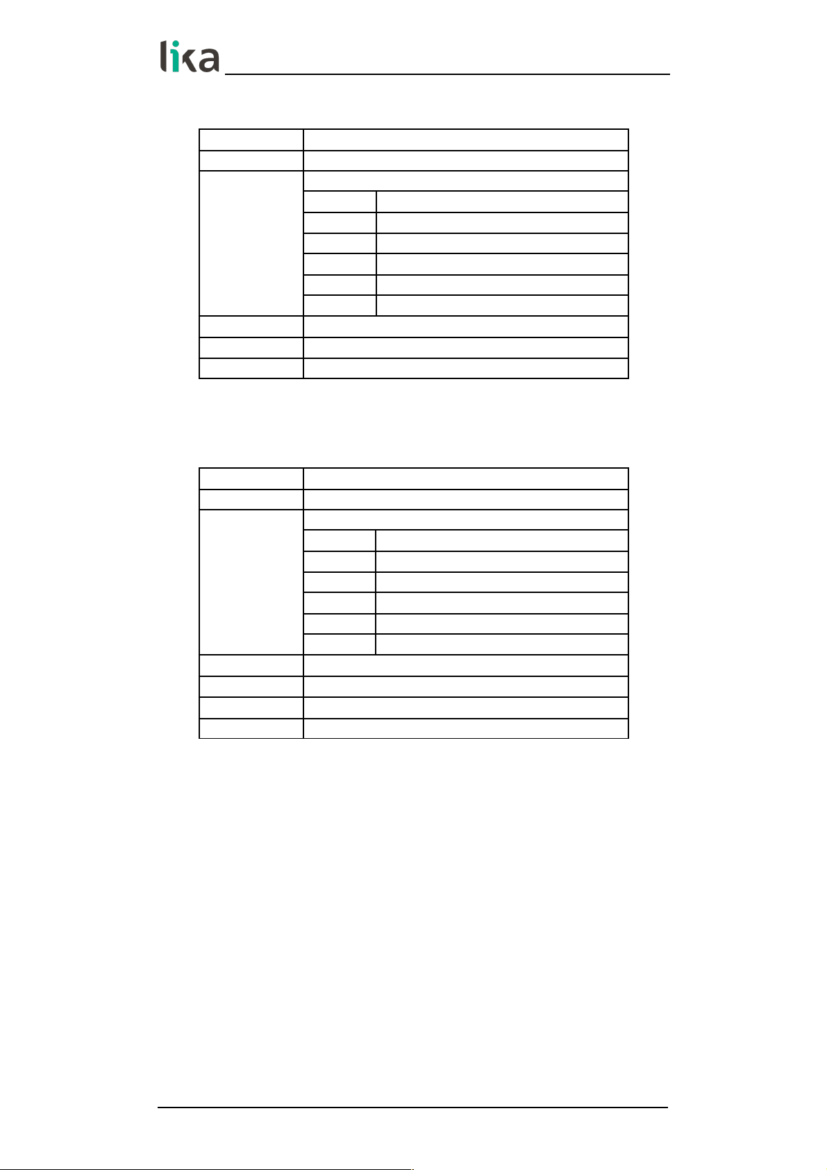
DDLM_Set_Prm with Class 1
Byte Parameter
0 … 9 Reserved for PROFIBUS network
10
Operating parameters
bit 0
Code sequence
bit 1
Class 2 functionality
bits 2 … 6 Reserved
bit 7
Exchange type
11 … 20 Reserved
MAN XAC80 PB E 1.0.odt 7 - Profibus® interface 41 of 60
Page 42
XAC80 Profibus-DP
®
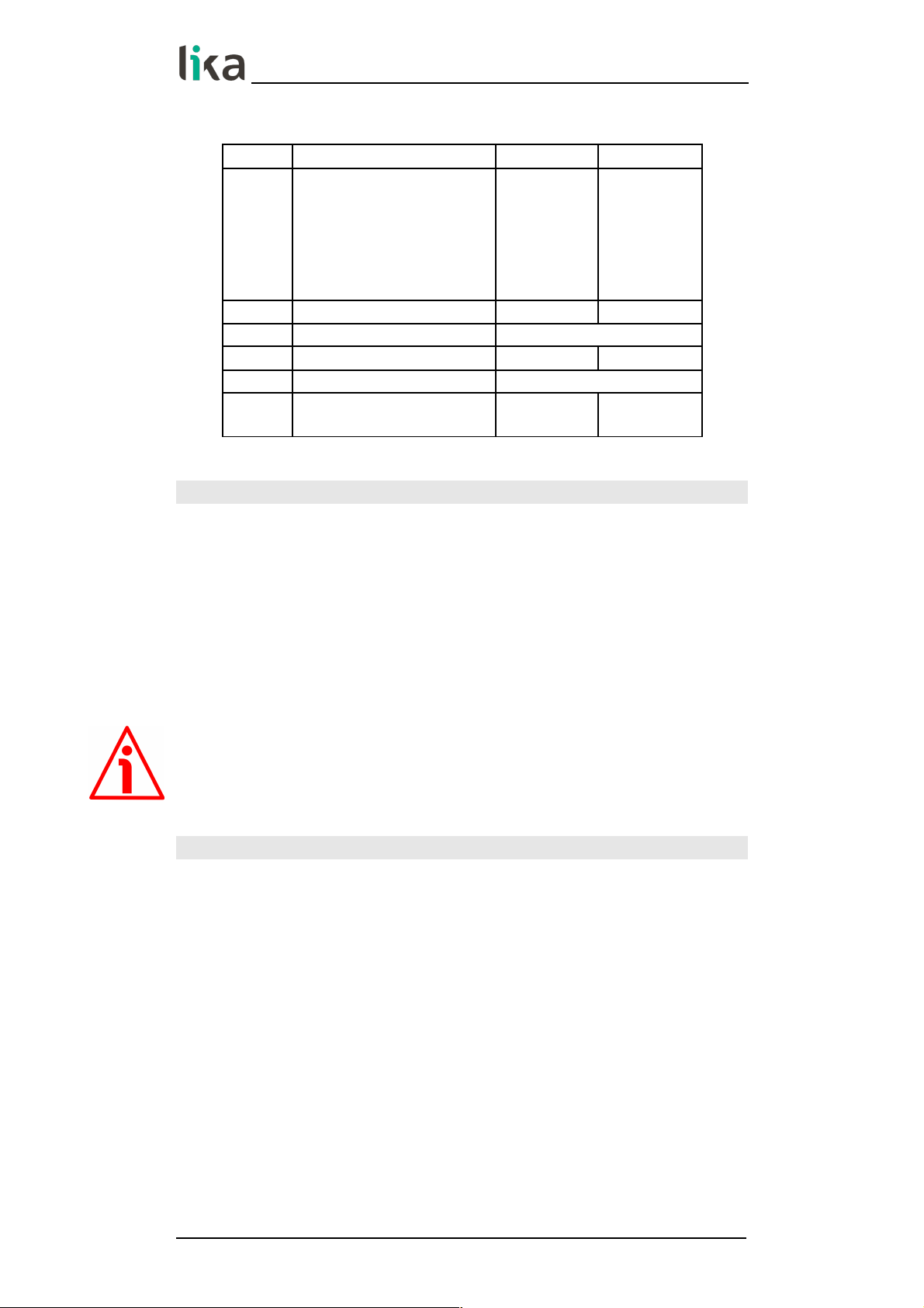
DDLM_Set_Prm with Class 2
Byte Parameter
0 … 9 Reserved for PROFIBUS network
10
Operating parameters
bit 0
Code sequence
bit 1
Class 2 functionality
bit 2 Reserved
bit 3
Scaling function control
bits 4 … 6 Reserved
bit 7
Exchange type
11 … 14
Counts per revolution
15 … 18
Total resolution
19 and 20 Reserved
DDLM_Set_Prm with Class 2 (+VEL)
Byte Parameter
0 … 9 Reserved for PROFIBUS
10
Operating parameters
bit 0
Code sequence
bit 1
Class 2 functionality
bit 2 Reserved
bit 3
Scaling function control
bits 4 ... 6 Reserved
bit 7
Exchange type
11 … 14
Counts per revolution
15 … 18
Total resolution
19
Velocity measure unit
20 Reserved
MAN XAC80 PB E 1.0.odt 7 - Profibus® interface 42 of 60
Page 43
XAC80 Profibus-DP
®
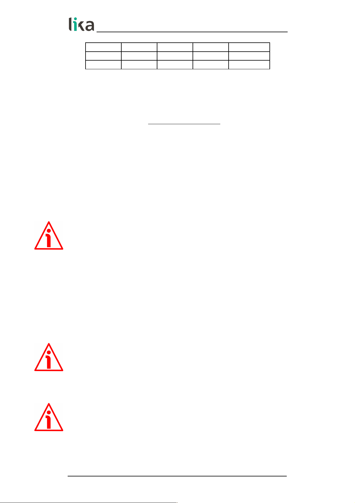
7.4.1 Byte 10 - Operating parameters
Bit Function bit = 0 bit = 1
0
Code sequence
Count up
information
with
clockwise
rotation
Count up
information
with
counter-
clockwise
rotation
1
Class 2 functionality
disabled
enabled
2 Reserved
3
Scaling function control
disabled
enabled
4 ... 6 Reserved
7
Exchange type
position
position +
velocity
Code sequence
This is intended to set whether the position value output by the transducer
increases (count up information) when the encoder shaft rotates clockwise (CW)
or counter-clockwise (CCW). When Code sequence = 0, the position value
increases when the encoder shaft rotates clockwise; on the contrary, when
Code sequence = 1, the position value increases when the encoder shaft
rotates counter-clockwise. CW and CCW rotations are viewed from the shaft
end.
Default = 0 (min. = 0, max. = 1)
WARNING
Every time you change the Code sequence, then you are required to set a new
preset value (see the Preset value parameter).
Class 2 functionality
This is only available when the encoder Class 2 or the encoder Class 2(+VEL) are
installed.
Two device classes are defined in the encoder profile, one mandatory class (Class
1) and one class with optional functions (Class 2). This encoder implements
functions of both Class 1 and Class 2 for encoders. For any information on the
available encoder classes see the “7.2 Classes of the Device profile” section on
page 39.
0 = Disabled = Encoder Class 1 is set.
1 = Enabled = Encoder Class 2 (or Class 2(+VEL)) is set.
Default = 1 (min. = 0, max. = 1)
MAN XAC80 PB E 1.0.odt 7 - Profibus® interface 43 of 60
Page 44

XAC80 Profibus-DP
®
Scaling function control
This is only available when the encoder Class 2 or the encoder Class 2(+VEL) are
installed.
When this option is disabled (bit 3 Scaling function control = 0 = DISABLED),
the device uses the hardware resolution, i.e. the hardware counts per revolution
and the hardware number of revolutions to arrange the absolute position
information, see the encoder data on the label applied to the device.
On the contrary, when it is enabled (bit 3 Scaling function control = 1 =
ENABLED), the device uses the custom resolution transmitted through the bytes
from 11 to 18 to calculate the position information (see the Counts per
revolution and Total resolution parameters).
For a correct use of this function see the “7.4.2 Bytes 11 … 14“ and “7.4.3 Bytes
15 … 18“ sections.
Default = 1 (min. = 0, max. = 1)
WARNING
When you enable the scaling function (Scaling function control = 1), please
enter scaled values next to the Counts per revolution and Total resolution
parameters that are consistent with the physical values. In the case of
inconsistent values, the system does not go online.
WARNING
Every time you enable the scaling function and/or change the scaled values (see
the Counts per revolution and Total resolution parameters), then you are
required to set a new preset value (see the the Preset value parameter).
WARNING
You can activate the custom values set next to the Counts per revolution and
Total resolution parameters only if Class 2 functionality = ENABLED.
If Scaling function control = ENABLED the set custom resolution values are
enabled and used by the encoder; on the contrary, if Scaling function control
= DISABLED you are allowed to set new resolution values, however they are not
enabled even if sent to the encoder: the encoder still goes on using the physical
values, NOT the new entered values, until you enable the Scaling function
control.
Exchange type
0 = Position = the device transmits only the position value (Class 1 and Class 2).
1 = Position + velocity = the device transmits both position and velocity values
(Class 2(+VEL)).
Default = 0 (min. = 0, max. = 0) for Class 1 and Class 2
Default = 1 (min. = 1, max. = 1) for Class 2 (+VEL)
MAN XAC80 PB E 1.0.odt 7 - Profibus® interface 44 of 60
Page 45

XAC80 Profibus-DP
®
7.4.2 Bytes 11 … 14
Counts per revolution
WARNING
This is only available when the encoder Class 2 or the encoder Class 2 (+VEL) are
installed.
You can activate a new value next to the Counts per revolution parameter
only if Class 2 functionality = ENABLED. If Scaling function control =
ENABLED the set resolution values are enabled and used by the encoder; on the
contrary, if Scaling function control = DISABLED you are allowed to set new
resolution values, however they are not enabled even if sent to the encoder: the
encoder still goes on using the physical values, NOT the new entered values,
until you enable the Scaling function control. See the “7.4.1 Byte 10 Operating parameters” section on page 43.
If Class 2 functionality = DISABLED or Scaling function control = DISABLED,
then the system uses the physical values to arrange the position information.
The Counts per revolution parameter allows to program a user specific
singleturn resolution (i.e. the desired number of information -distinguishable
steps- per revolution).
Byte 11 12 13 14
Bit 31-24 23-16 15-8 7-0
Data 231 to 2
24
223 to 2
16
215 to 2
8
27 to 2
0
The custom singleturn resolution value must be less than or equal to the
physical singleturn resolution (hardware counts per revolution value).
Setting a value greater than allowed causes the resolution to be forced to the
Hardware counts per revolution value.
You are allowed to set any integer value less than or equal to the Hardware
counts per revolution. However we suggest setting a value that is a power of 2
(1, 2, 4, … 2,048, 4,096, …). This is meant to avoid counting errors (refer also to
the “7.8 "Dead Zone"” section on page 55).
Default = 262,144 (min. = 1, max. = 262,144) for XAC8018/1
Default = 8,192 (min. = 1, max. = 8,192) for XAC8013/16384
Default = 65,536 (min. = 1, max. = 65,536) for XAC8016/16384
WARNING
When you set a new value next to the Counts per revolution parameter, please
always check also the Total resolution parameter value and be sure that the
resulting number of revolutions complies with the Hardware number of
revolutions of the device (1 or 16,384, see the order code).
Let's suppose that our encoder is programmed as follows:
Counts per revolution: 8,192 cpr
Total resolution = 134,217,72810 = 8,192 (cpr) * 16,384 (rev.)
Let's set a new singleturn resolution, for instance: Counts per revolution =
360.
MAN XAC80 PB E 1.0.odt 7 - Profibus® interface 45 of 60
Page 46

XAC80 Profibus-DP
®
If we do not change the Total resolution value at the same time, we will get
the following result:
Number of revolutions =
134,217,728 (Total resolution)
= 372,827.02
360 (Counts per revolution)
As you can see, the encoder is required to carry out almost 373,000 revolutions,
this cannot be as the hardware number of revolutions is, as stated, max. 16,384.
When this happens, the encoder falls into an error.
WARNING
When you enable the scaling function (Scaling function control = 1), please
enter scaled values next to the Counts per revolution and Total resolution
parameters that are consistent with the physical values. In the case of
inconsistent values, the system does not go online.
WARNING
Every time you change the value in this parameter, then you are required to set
a new preset value (see the the Preset value parameter).
7.4.3 Bytes 15 … 18
Total resolution
WARNING
This is only available when the encoder Class 2 or the encoder Class 2 (+VEL) are
installed.
You can activate a new value next to the Total resolution item only if Class 2
functionality = ENABLED. If Scaling function control = ENABLED the set
resolution values are enabled and used by the encoder; on the contrary, if
Scaling function control = DISABLED you are allowed to set new resolution
values, however they are not enabled even if sent to the encoder: the encoder
still goes on using the physical values, NOT the new entered values, until you
enable the Scaling function control. See the “7.4.1 Byte 10 - Operating
parameters” section on page 43.
If Class 2 functionality = DISABLED or Scaling function control = DISABLED,
then the system uses the physical values to arrange the position information.
This parameter is intended to set a custom number of distinguishable steps over
the total measuring range. The total resolution of the encoder results from the
product of Counts per revolution by the required Number of revolutions.
MAN XAC80 PB E 1.0.odt 7 - Profibus® interface 46 of 60
Page 47
XAC80 Profibus-DP
®
Byte 15 16 17 18
Bit 31-24 23-16 15-8 7-0
Data 231 to 2
24
223 to 2
16
215 to 2
8
27 to 2
0
Allowed values are less than or equal to the Total hardware resolution value.
Setting a value greater than allowed causes the resolution to be forced to the
Total hardware resolution value.
Number of revolutions =
Total resolution
Counts per revolution
We recommend the Number of revolutions to be set to a power of 2. This is
meant to avoid problems when using the device in endless operation (when
crossing the physical zero) and entering the "Red Zone" (see the “7.8 "Dead
Zone"” section on page 55).
Default = 262 144 (min. = 1, max. = 262 144) for XAC8018/1
Default = 134 217 728 (min. = 1, max. = 134 217 728) for XAC8013/16384
Default = 1 073 741 824 (min. = 1, max. = 1 073 741 824) for XAC8016/16384
WARNING
When you set a new value next to the Total resolution parameter, please
always check also the Counts per revolution parameter value and be sure that
the resulting number of revolutions complies with the Hardware number of
revolutions of the device.
Let's suppose our encoder is programmed as follows:
Counts per revolution: 8,192
Total resolution = 33,554,43210 = 8,192 (cpr) * 4,096 (rev.)
Let's set a new total resolution, for instance: Total resolution = 360.
As the Total resolution must be greater than or equal to the Counts per
revolution, the above setting is not allowed. When this happens, the encoder
falls into an error.
WARNING
When you enable the scaling function (Scaling function control = 1), please
enter scaled values next to the Counts per revolution and Total resolution
parameters that are consistent with the physical values. In the case of
inconsistent values, the system does not go online.
WARNING
Every time you change the value in this parameter, then you are required to set
a new preset value (see the the Preset value parameter).
MAN XAC80 PB E 1.0.odt 7 - Profibus® interface 47 of 60
Page 48

XAC80 Profibus-DP
®
EXAMPLE
“XAC8018/1”: singleturn encoder
Hardware counts per revolution = 18 bits/turn (218 = 262 144 cpr)
Hardware number of turns = 1
Total hardware resolution = 18 bits (262 144 1 = 262 144)
“XAC8016/16384”: multiturn encoder
Hardware counts per revolution = 16 bits/turn (216 = 65,536 cpr)
Hardware number of turns = 14 bit (16,384 turn)
Total hardware resolution = 30 bits (65,536 16,384 = 230 = 1 073
741 824)
EXAMPLE
Multiturn encoder “XAC8016/16384”.
The resolution is:
Hardware counts per revolution = 65,536 (216)
Hardware number of turns = 16,384 (214)
Total hardware resolution = 1 073 741 824 (230)
2,048 steps per revolution 1,024 turns are required:
Enable the scaling function (Class 2 functionality = 1; Scaling function
control = 1); byte 10 = 0A hex (bit 1 = bit 3 = “1”)
Custom resolution per turn = Counts per revolution = 2,048 cpr; bytes 11
… 14 = 0000 0800 hex
Total resolution = 2,048 1,024 = 2 097 152: byte 15 … 18 = 0020 0000
hex.
NOTE
When new values are set next to the Counts per revolution and/or Total
resolution parameters, a new Preset value setting is required according to the
new resolution.
7.4.4 Byte 19
Velocity measure unit
This byte is available only when Class 2 (+VEL) is set (see also Class 2
functionality and Exchange type items).
It defines the unit of measurement for the speed value transmitted by the
device.
00 = step/s (steps per second);
01 = rpm (revolutions per minute).
Default = 0 (min. = 0, max. = 1)
MAN XAC80 PB E 1.0.odt 7 - Profibus® interface 48 of 60
Page 49

XAC80 Profibus-DP
®
7.5 DDLM_Chk_Cfg
The Configuration function allows the Master to send configuration data to the
Slave for any check operation. The main purpose of this function is to set the
number of bytes used for the Data_Exchange as viewed from Master side.
Chk_Cfg message structure (1 byte):
bit 7 = Consistency (=”1”)
bit 6 = Word format (“0”=byte,“1”=word=4 bytes)
bit 5 and 4 = In/out data (“01”=Input, ”10”=output)
bit 3 … 0 = Length code
EXAMPLE
bit
7 6 5 4 3 2 1 0
Data
1 1 0 1 0 0 0 1 D1h
1 1 0 1 0 0 1 1 D3h
1 1 1 0 0 0 0 1 E1h
Class 1 and Class 2:
D1hex = 4 byte input
E1hex = 4 byte output
Class 2(+VEL):
D3hex = 8 byte input
E1hex = 4 byte output
7.6 DDLM_Data_Exchange
This is the normal operation status of the system. The Slave (for both Class 1 and
Class 2) can transmit the Position value (and the speed value -Position and
velocity values- if Class 2+VEL is set) and receive the Preset value from the
Master. See also the Exchange type parameter on page 44.
Position value
when either Class 1 or Class 2 is set (Encoder Master)
Byte 1 2 3 4
Bit 31-24 23-16 15-8 7-0
Data 231 to 2
24
223 to 2
16
215 to 2
8
27 to 2
0
See also the Exchange type parameter.
It has a mandatory length of 32 bits and is right aligned in the data field.
This parameter contains the current position of the encoder.
If the scaling function is enabled, the output value is scaled according to the
scaling parameters (see Scaling function control on page 44).
MAN XAC80 PB E 1.0.odt 7 - Profibus® interface 49 of 60
Page 50

XAC80 Profibus-DP
®
Position and velocity values
when Class 2 (+VEL) is set (Encoder Master)
Byte 1 … 4 5 … 8
Bit 31-24 … 7-0 31-24 … 7-0
Position Velocity
For more information on the position value refer to the previous Position value
parameter.
See also the Exchange type parameter.
The velocity value is expressed according to the setting in the Velocity measure
unit parameter.
Preset value
when any Class is set (Master Slave)
Byte 1 2 3 4
Bit 31-24 23-16 15-8 7-0
Data 231 to 2
24
223 to 2
16
215 to 2
8
27 to 2
0
This parameter allows to set the encoder position to a Preset value. The Preset
function is meant to assign a desired value to a physical position of the encoder.
The chosen physical position will get the value set next to this item and all the
previous and following positions will get a value according to it. This function is
useful, for example, when the zero position of the encoder and the zero position
of the axis need to match. The preset value will be set for the position of the
encoder in the moment when the preset value is sent. The Preset value is sent
by the Master to the Slave in Data_Exchange mode by setting bit 31 = “1” for 3
cycles.
The MSB of the preset value controls the preset function in the following way:
Normal operating mode: MSB = 0 (bit 31): the encoder will make no change in
the preset value.
Preset mode: MSB = 1 (bit 31): with the MSB = 1 the encoder accepts the
transferred value (bits 0 ... 30) as a preset value in binary code.
- If Scaling function control = DISABLED, then
the Preset value must be less than or equal to the Total hardware
resolution.
- If Scaling function control = ENABLED, then
the Preset value must be less than or equal to the Total resolution.
EXAMPLE
Preset value to be set = 0000 1000hex
Current Position value = 0005 5000hex
MAN XAC80 PB E 1.0.odt 7 - Profibus® interface 50 of 60
Page 51

XAC80 Profibus-DP
®
Byte 1 2 3 4
Cycle
Bit 31-24 23-16 15-8 7-0
1°
MS 80 00 10 00
SM 00 05 50 00
2°
MS 80 00 10 00
SM 00 05 50 00
3°
MS 80 00 10 00
SM 00 00 10 00
NOTE
We suggest setting the Preset value when the shaft is in stop.
The new Preset value is saved immediately after receipt.
WARNING
Check the value in the Preset value parameter and perform the preset
operation every time you change the value next to the Code sequence, Counts
per revolution and Total resolution parameters.
MAN XAC80 PB E 1.0.odt 7 - Profibus® interface 51 of 60
Page 52

XAC80 Profibus-DP
®
7.7 DDLM_Slave_Diag
The Master device can send a request to the Slave device for diagnostic
information at any time.
This encoder provides 16-byte diagnostic information.
Diagnostic information consists of two parts: a standard diagnostic information
(bytes 0 … 5) and an extended diagnostic information (bytes 6 … 15). The
standard diagnostic information complies with the guidelines contained in the
“Profibus specification – Normative parts according to the European Standard
EN 50 170 volume 2” publication. While the extended diagnostic information
contains the device related encoder diagnostic information; the DP-Slave
specific diagnostic is entered in this area. The extended diagnostic information
complies with the specifications contained in the “Profibus-DP Profile For
Encoders” publication. The length of the extended diagnostic information for
encoder is specified in byte 6 of the diagnostic message.
16-byte diagnostic information:
Figure 3 - 16-byte Diagnostic information
Byte Description Byte Description
0
Station_Status_1
8
Operating status
1
Station_Status_2
9
Encoder type
2
Station_Status_3
10 MSB
Singleturn resolution
3
Master_Add
11
4 MSB
Ident_Number
12
5 LSB 13 LSB
6
Extended diagnostic header
14 MSB
Number of distinguishable
revolutions
15 LSB
7
Alarms
Station_Status_1
Byte 0. The first 5 bytes are defined in the “Profibus specification” document in
compliance with the European Standard EN 50170 volume 2. For any
information on the meaning of the individual bits in the Station_Status_1 byte
refer to the “Profibus specification” document.
MAN XAC80 PB E 1.0.odt 7 - Profibus® interface 52 of 60
Page 53

XAC80 Profibus-DP
®
Station_Status_2
Byte 1. The first 5 bytes are defined in the “Profibus specification” document in
compliance with the European Standard EN 50170 volume 2. For any
information on the meaning of the individual bits in the Station_Status_2 byte
refer to the “Profibus specification” document.
Station_Status_3
Byte 2. The first 5 bytes are defined in the “Profibus specification” document in
compliance with the European Standard EN 50170 volume 2. For any
information on the meaning of the individual bits in the Station_Status_3 byte
refer to the “Profibus specification” document.
Master_Add
Byte 3. The address of the DP-Master which has parametrized this DP-Slave is
entered in this byte, in the example (Figure 3): 02 hex. The first 5 bytes are
defined in the “Profibus specification” document in compliance with the
European Standard EN 50170 volume 2. For any information on the meaning of
the Master_Add byte refer to the “Profibus specification” document.
Ident_Number
Bytes 4 and 5. The manufacturer identifier is given for a DP-Device. This
identifier can be used both for verification purpose and for the exact
identification. In the example (Figure 3): 16 55 hex. The first 5 bytes are defined
in the “Profibus specification” document in compliance with the European
Standard EN 50170 volume 2. For any information on the meaning of the
Ident_Number bytes refer to the “Profibus specification” document.
Extended diagnostic header
Byte 6. The Extended diagnostic header specifies the length of the Encoder
diagnostics (extended diagnostic information) including the header byte, in the
example (Figure 3): 0A hex = 10 dec. The value is expressed in hexadecimal
format. For any information on the meaning of the Extended diagnostic
header byte refer to the “Profibus-DP Profile For Encoders” document.
Alarms
Byte 7. This byte is intended to show the status of the alarms specified in the
“Profibus-DP Profile For Encoders” document. This device does not provide the
specified alarms management, thus this byte is set to logical low (00 hex). For
any information on the meaning of the individual bits in the Alarms byte refer
to the “Profibus-DP Profile For Encoders” document.
MAN XAC80 PB E 1.0.odt 7 - Profibus® interface 53 of 60
Page 54

XAC80 Profibus-DP
®
Operating status
Byte 8. This byte is intended to give information on the Encoder internal
parameters, in other words it informs on the status of DDLM_Set_Prm byte 10
Operating parameters (refer to the “7.4.1 Byte 10 - Operating parameters”
section on page 43). In the example of Figure 3: 8A hex = 10001010 bin, that is:
bit 0 = 0: Code sequence = count up information with clockwise rotation
bit 1 = 1: Class 2 functionality = enabled
bit 2 = 0 = not used
bit 3 = 1: Scaling function control = enabled
bits 4 … 6 = 0 = not used
bit 7 = 1: Exchange type = Position + velocity information transmission
For any information on the meaning of the individual bits in the Operating
status byte refer to the “Profibus-DP Profile For Encoders” document.
Encoder type
Byte 9. This byte is intended to give information on the Encoder type. The value
is expressed in hexadecimal format. In the example of Figure 3: 01 hex = “Multiturn absolute rotary encoder”. For any information on the meaning of the
Encoder type byte refer to the “Profibus-DP Profile For Encoders” document.
Singleturn resolution
Bytes 10 … 13. These bytes are intended to provide the number of measuring
steps per revolution that are output for the absolute singleturn position value
(physical singleturn resolution). In the example of Figure 3: 00 01 00 00 hex =
65,536 dec, 16-bit physical singleturn resolution. For any information on the
meaning of the Singleturn resolution bytes refer to the “Profibus-DP Profile
For Encoders” document.
Number of distinguishable revolutions
Bytes 14 and 15. These bytes are intended to provide the number of
distinguishable revolutions that the encoder can output. In the example of
Figure 3: 40 00 hex, i.e. 16,384 revolutions. For any information on the meaning
of the Number of distinguishable revolutions bytes refer to the “Profibus-DP
Profile For Encoders” document.
MAN XAC80 PB E 1.0.odt 7 - Profibus® interface 54 of 60
Page 55
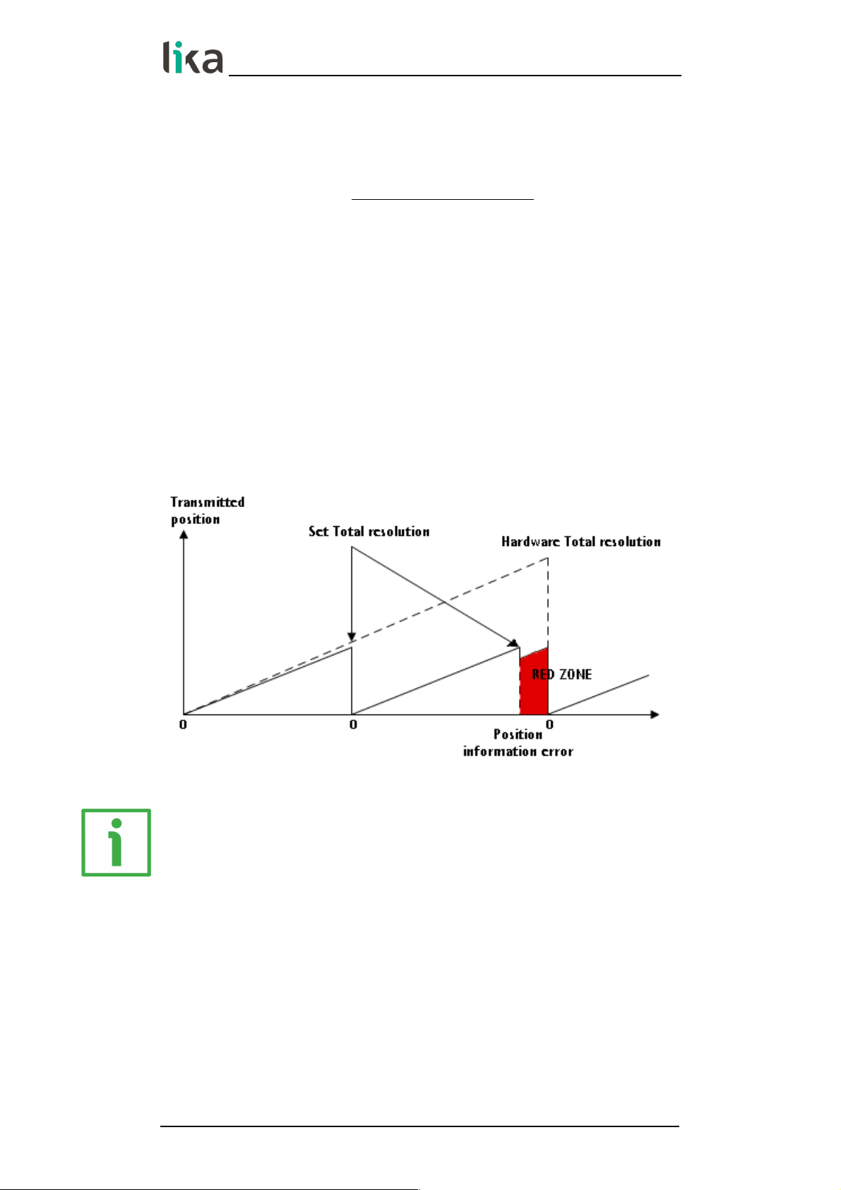
XAC80 Profibus-DP
®
7.8 "Dead Zone"
The so-called "Red Zone" occurs when:
Number of revolutions =
Total resolution
Counts per revolution
is not a power of 2.
When this problem arises, the device must operate within the “red zone” for a
certain number of positions. The size of the “red zone” is variable. To calculate it
we must subtract the Total resolution value from the Hardware total
resolution of the device as many times as until the difference is less than the
the set Total resolution value. When the encoder crosses the limit of the last
Total resolution section thus entering the “red zone”, a counting error occurs,
i.e. a jump in the position count. The problem can be represented graphically in
the Figure below.
EXAMPLE
“XAC8016/16384PB...”: multiturn encoder
Hardware counts per revolution = 65,536 (216)
Hardware number of turns = 16,384 (214)
Total hardware resolution = 1 073 741 824 (230)
Set parameter values:
Counts per revolution = 50,000
Number of revolutions = 8,000
Total resolution = 400 000 000
MAN XAC80 PB E 1.0.odt 7 - Profibus® interface 55 of 60
Page 56

XAC80 Profibus-DP
®
Hardware number of turns
=
16,384
= 2.048
Number of revolutions 8,000
It follows that, for 384 revolutions (16,384 - 2 * 8,000 = 384), the encoder will
operate within the "Red Zone" limits.
NOTE
• When the encoder is operating within the limits of the “Red Zone” (i.e.
for 50,000 cpr * 384 revolutions = 19 200 000 counts, from 380 799 999
to 399 999 999), the transmitted position is consistent with the set
resolution: it is calculated so that the last position within the “red zone”
before crossing the zero position is Total resolution - 1.
• Please be careful using the position information sent by the encoder
when it is operating within the limits of the “Red Zone”. When the
encoder changes from normal status to the “Red Zone” status (and vice
versa) a jump of position occurs. See the Figure above: when entering
the “red zone” the position information jumps from 399 999 999 to 380
799 999.
MAN XAC80 PB E 1.0.odt 7 - Profibus® interface 56 of 60
Page 57

XAC80 Profibus-DP
®
8 - Default parameters list
Parameters list Default values
Code sequence
0 = CW = count up
information with clockwise
rotation
Class 2 functionality
1 = Encoder Class 2 or
Encoder Class 2 (+VEL)
Scaling function control 1 = ENABLED
Exchange type
0 = position (Class 1 and
Class 2)
1 = position + velocity (Class
2 (+VEL))
Counts per revolution
XAC8018/1 = 262,144
XAC8013/16384 = 8,192
XAC8016/16384 = 65,536
Total resolution
XAC8018/1 = 262,144
XAC8013/16384 =
134,217,728
XAC8016/16384 =
1,073,741,824
Velocity measure unit 0 = steps/s
MAN XAC80 PB E 1.0.odt 8 - Default parameters list 57 of 60
Page 58

This page intentionally left blank
Page 59

This page intentionally left blank
Page 60

Document release Release date Description HW SW
GSD file
version
1.0 08.08.2018 1st issue R1 2.0 V1
Lika Electronic
Via S. Lorenzo, 25 • 36010 Carrè (VI) • Italy
Tel. +39 0445 806600
Fax +39 0445 806699
info@lika.biz • www.lika.biz
 Loading...