

Page 1
User's guide
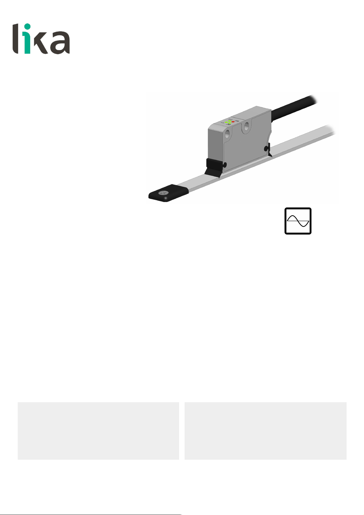
SMS12
• Incremental linear encoder for 1-mm pole pitch tape
• Resolution 1 mm / 0.039”
• Measuring length up to 100 m / 328 ft
• IP67 protection rate
• 1Vpp sinusoidal outputs
• With external limit switches to mark off the travel
Suitable for the following models:
• SMS12
Table of Contents
Safety summary 6
Identification 8
Mechanical installation 9
Electrical connection 18
Maintenance and troubleshooting 28
Lika Electronic • Tel. +39 0445 806600 • info@lika.biz • www.lika.biz
Smart encoders & actuators
Page 2

This publication was produced by Lika Electronic s.r.l. 2018. All rights reserved. Tutti i diritti riservati. Alle Rechte vorbehalten. Todos los
derechos reservados. Tous droits réservés.
This document and information contained herein are the property of Lika Electronic s.r.l. and shall not be reproduced in whole or in
part without prior written approval of Lika Electronic s.r.l. Translation, reproduction and total or partial modification (photostat copies,
film and microfilm included and any other means) are forbidden without written authorisation of Lika Electronic s.r.l.
The information herein is subject to change without notice and should not be construed as a commitment by Lika Electronic s.r.l. Lika
Electronic s.r.l. reserves the right to make all modifications at any moments and without forewarning.
This manual is periodically reviewed and revised. As required we suggest checking if a new or updated edition of this document is
available at Lika Electronic s.r.l.'s website. Lika Electronic s.r.l. assumes no responsibility for any errors or omissions in this document.
Critical evaluation of this manual by the user is welcomed. Your comments assist us in preparation of future documentation, in order
to make it as clear and complete as possible. Please send an e-mail to the following address info@lika.it for submitting your
comments, suggestions and criticisms.
Page 3

General contents
User's guide............................................................................................................................................................................................1
General contents.............................................................................................................................................................................3
Typographic and iconographic conventions...................................................................................................................4
Preliminary information..............................................................................................................................................................5
1 Safety summary..................................................................................................................................... 6
1.1 Safety.............................................................................................................................................................................6
1.2 Electrical safety.........................................................................................................................................................6
1.3 Mechanical safety....................................................................................................................................................7
2 Identification......................................................................................................................................... 8
3 Mechanical installation....................................................................................................................... 9
3.1 Overall dimensions...................................................................................................................................................9
3.2 Sensor and scale / ring combination.............................................................................................................10
3.3 Magnetic tape.........................................................................................................................................................10
3.4 Magnetic rings........................................................................................................................................................10
3.5 Mounting the sensor with magnetic tape..................................................................................................11
3.6 Mounting the sensor with “R” / “T” Reference..........................................................................................13
3.7 Mounting the sensor with LS1 and LS2 limit switches.........................................................................14
3.8 Measuring length..................................................................................................................................................15
3.9 Mounting the sensor with MRI magnetic rings.......................................................................................15
3.10 Standard counting direction..........................................................................................................................17
3.11 Optional cleaning wipers (Figure 1).............................................................................................................17
4 Electrical connection.......................................................................................................................... 18
4.1 M10 cable connection.........................................................................................................................................18
4.2 M10 cable specifications....................................................................................................................................19
4.3 Connection of the shield....................................................................................................................................20
4.4 Ground connection...............................................................................................................................................20
4.5 AB0, /AB0 output channels...............................................................................................................................21
4.6 Counting direction................................................................................................................................................21
4.7 Reference “R” / “T”.................................................................................................................................................22
4.8 Voltage signals........................................................................................................................................................23
4.9 LS1 and LS2 limit switches................................................................................................................................23
4.10 Diagnostic LEDs (Figure 10).............................................................................................................................25
4.11 Recommended circuit........................................................................................................................................27
5 Maintenance and troubleshooting................................................................................................. 28
Page 4
Typographic and iconographic conventions
In this guide, to make it easier to understand and read the text the following typographic and
iconographic conventions are used:
• parameters are coloured in GREEN;
• alarms are coloured in RED;
• states are coloured in FUCSIA.
When scrolling through the text some icons can be found on the side of the page: they are expressly
designed to highlight the parts of the text which are of great interest and significance for the user.
Sometimes they are used to warn against dangers or potential sources of danger arising from the use of
the device. You are advised to follow strictly the instructions given in this guide in order to guarantee the
safety of the user and ensure the performance of the device. In this guide the following symbols are
used:
This icon, followed by the word WARNING, is meant to highlight the parts of the
text where information of great significance for the user can be found: user must
pay the greatest attention to them! Instructions must be followed strictly in order
to guarantee the safety of the user and a correct use of the device. Failure to heed
a warning or comply with instructions could lead to personal injury and/or damage
to the unit or other equipment.
This icon, followed by the word NOTE, is meant to highlight the parts of the text
where important notes needful for a correct and reliable use of the device can be
found. User must pay attention to them! Failure to comply with instructions could
cause the equipment to be set wrongly: hence a faulty and improper working of
the device could be the consequence.
This icon is meant to highlight the parts of the text where suggestions useful for
making it easier to set the device and optimize performance and reliability can be
found. Sometimes this symbol is followed by the word EXAMPLE when instructions
for setting parameters are accompanied by examples to clarify the explanation.
Page 5

Preliminary information
This guide is designed to provide the most complete and exhaustive information the operator needs to
correctly and safely install and operate the SMS12 incremental linear encoder.
SMS12 linear encoder is designed to measure linear or angular displacements on industrial machines and
automation systems. The measurement system includes a magnetic tape / magnetic ring and a magnetic
sensor. The tape / ring has alternating magnetic north/south poles that are magnetized at a fixed
distance called the pole pitch. The pole pitch is 1 mm. The conversion electronics inside the sensor
translates the magnetic fields of the tape / ring into sinusoidal electrical signals (1Vpp) equivalent to
those of an incremental encoder or a linear scale. The readhead must be paired with the appropriated
magnetic tape / ring (see the “3.2 Sensor and scale / ring combination” section on page 10).
SMS12 encoder is equipped with two sensors for detecting external limit switches (order code LKM1309/LS). They are designed to mark out the travel of the application. The activation of the sensors is
shown through LEDs.
In addition it also integrates a sensor for detecting an external Reference magnet (order code LKM1309/1) and is equipped with four diagnostic LEDs.
The flexibility of the scale allows the sensor to be used for both linear and angular applications.
Furthermore it can be installed also on round surfaces and magnetic rings.
Page 6
SMS12
1 Safety summary
1.1 Safety
• Always adhere to the professional safety and accident prevention
regulations applicable to your country during device installation and
operation;
• installation and maintenance operations have to be carried out by
qualified personnel only, with power supply disconnected and stationary
mechanical parts;
• device must be used only for the purpose appropriate to its design: use for
purposes other than those for which it has been designed could result in
serious personal and/or the environment damage;
• high current, voltage and moving mechanical parts can cause serious or
fatal injury;
• warning ! Do not use in explosive or flammable areas;
• failure to comply with these precautions or with specific warnings
elsewhere in this manual violates safety standards of design, manufacture,
and intended use of the equipment;
• Lika Electronic assumes no liability for the customer's failure to comply
with these requirements.
1.2 Electrical safety
• Turn OFF the power supply before connecting the device;
• connect according to the explanation in the ”Electrical connection” section
on page 18;
• the wires of unused output signals must be cut at different lengths and
insulated singularly;
• in compliance with 2014/30/EU norm on electromagnetic
compatibility, the following precautions must be taken:
- before handling and installing the equipment, discharge
electrical charge from your body and tools which may come in touch
with the device;
- power supply must be stabilized without noise; install EMC filters on
device power supply if needed;
- always use shielded cables (twisted pair cables whenever possible);
- avoid cables runs longer than necessary;
- avoid running the signal cable near high voltage power cables;
- mount the device as far as possible from any capacitive or inductive
noise source; shield the device from noise source if needed;
- to guarantee a correct working of the device, avoid using strong magnets
on or near by the unit;
MAN SMS12 E 1.1 Safety summary 6 of 32
Page 7
SMS12
- minimize noise by connecting the cable shield and the frame to ground.
Make sure that ground is not affected by noise. The connection point to
ground can be situated both on the device side and on user’s side. The
best solution to minimize the interference must be carried out by the
user;
- do not stretch the cable; do not pull or carry by cable; do not use the
cable as a handle.
1.3 Mechanical safety
• Install the device following strictly the information in the “Mechanical
installation” section on page 9;
• mechanical installation must be carried out with stationary mechanical
parts;
• do not disassemble the unit;
• do not tool the unit;
• delicate electronic equipment: handle with care; do not subject the device
to knocks or shocks;
• protect the unit against acid solutions or chemicals that may damage it;
• respect the environmental characteristics of the product;
• we suggest installing the unit providing protection means against waste,
especially swarf as turnings, chips, or fillings; should this not be possible,
please make sure that adequate cleaning measures (as for instance
brushes, scrapers, jets of compressed air, etc.) are in place in order to
prevent the sensor and the magnetic tape from jamming.
MAN SMS12 E 1.1 Safety summary 7 of 32
Page 8
SMS12
2 Identification
Device can be identified through the order code and the serial number printed
on the label applied to its enclosure. Information is listed in the delivery
document too. Please always quote the order code and the serial number when
reaching Lika Electronic for purchasing spare parts or needing assistance. For
any information on the technical characteristics of the product refer to the
technical catalogue.
Warning: encoders having order code ending with "/Sxxx" may have
mechanical and electrical characteristics different from standard and
be supplied with additional documentation for special connections
(Technical Info).
MAN SMS12 E 1.1 Identification 8 of 32
Page 9
SMS12
3 Mechanical installation
WARNING
Installation must be carried out by qualified personnel only, with power supply
disconnected and mechanical parts compulsorily in stop.
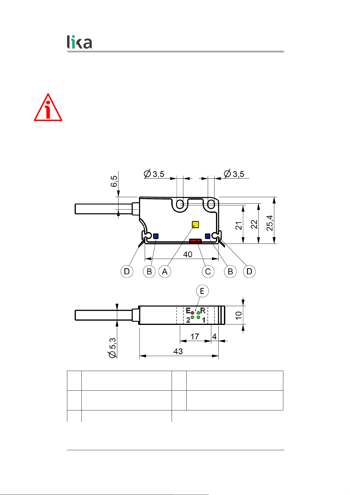
3.1 Overall dimensions
(values are expressed in mm)
A
Reference sensor “R” / “T” (page
22)
D Optional cleaning wipers (page 17)
B
Limit switch sensors “LS” (page
23)
E Diagnostic LEDs (page 25)
C Incremental sensor
MAN SMS12 E 1.1 Mechanical installation 9 of 32
Page 10

SMS12
3.2 Sensor and scale / ring combination
The sensor has to be compulsorily paired with its specific type of magnetic scale
or ring as indicated in the table below. For any information on the scale or ring
please refer to the specific documentation.
Sensor MT tape MRI ring
SMS12
MT10 MRI/xxx-xxx-1
3.3 Magnetic tape
As stated, the sensor model must be compulsorily paired with its specific type of
magnetic scale (see the previous section). For detailed information on the tape
and how to mount it properly, please refer to the specific technical
documentation.
Make sure that the mechanical installation complies with the system's
requirements for distance, planarity and parallelism between the readhead and
the scale indicated in Figure 2 all along the whole measuring length.
MT magnetic tape can be provided with a cover strip to protect its magnetic
surface (see the order code of the magnetic tape).
You can mount the readhead in both directions over the tape. The arrow in
Figure 1 indicates the standard counting direction (the rising edge of A signal
leads the rising edge of B signal) when the sensor moves in the direction
indicated by the arrow; further information in the “4.6 Counting direction”
section on page 21.
The external “R” / “T” Reference magnet order code LKM-1309/1 and the limit
switches “LS” order code LKM-1309/LS must be compulsorily installed as
shown in Figure 3 and Figure 4. For complete information please refer to the
“3.6 Mounting the sensor with “R” / “T” Reference” section on page 13; and to
the “3.7 Mounting the sensor with LS1 and LS2 limit switches” section on page
14.
3.4 Magnetic rings
The flexibility of the scale allows the sensor to be used for both linear and
angular applications. Furthermore it can be installed also on round surfaces and
magnetic rings.
As stated, the sensor model must be compulsorily paired with its specific type of
magnetic ring (see the “3.2 Sensor and scale / ring combination” section).
MAN SMS12 E 1.1 Mechanical installation 10 of 32
Page 11

SMS12
3.5 Mounting the sensor with magnetic tape
Figure 1 - Encoder / tape mounting gap
Make sure that the mechanical installation complies with the system
requirements concerning distance, planarity and parallelism between the sensor
and the scale as shown in Figure 2. Avoid contact between the parts.
Install the unit providing protection means against waste, especially swarf as
turnings, chips or filings; should this not be possible, please make sure that
adequate cleaning measures (as for instance brushes, scrapers, jets of
compressed air, etc.) are in place in order to prevent the sensor and the
magnetic scale from jamming. We suggest installing the optional cleaning
wipers order code KIT WIPERS.
Fix the sensor by means of two M3 15 mm min. long cylinder head screws
inserted in the provided slots.
The recommended tightening torque is 1.1 Nm.
The recommended minimum bend radius of the cable is: R 42 mm.
Install the sensor and the magnetic scale as shown in the Figure. As previously
stated, the arrow is intended to indicate the standard counting direction (the
rising edge of A signal leads the rising edge of B signal).
Please note that the MT magnetic scale can be provided with a cover strip to
protect its magnetic surface (see the order code). Therefore the distance
between the sensor and the magnetic scale is different whether the cover strip
is applied.
The distance D (see Figure 1) between the bottom of the encoder and the
MT magnetic scale must be as follows:
Sensor
Distance D between
sensor and MT tape
Distance D between
sensor and cover strip
SMS12
0.1 mm 0.5 mm
0.004” 0.019”
0.1 mm 0.3 mm
0.004” 0.012”
MAN SMS12 E 1.1 Mechanical installation 11 of 32
Page 12

SMS12
For better operation we suggest the following distance D:
Sensor
Recommended distance D between sensor and MT
tape
SMS12
0.25 mm 0.010”
WARNING
Make sure that the mechanical installation complies with the system's
requirements for distance, planarity and parallelism between the readhead and
the scale as shown in Figure 2 all along the whole measuring length.
Figure 2 - Encoder / tape mounting tolerances
MAN SMS12 E 1.1 Mechanical installation 12 of 32
Page 13

SMS12
3.6 Mounting the sensor with “R” / “T” Reference
The Reference signal is available
with "R" order code (RS-422 level
signals) or “T” order code (1Vpp
level signals) and in combination
with LKM-1309/1 Reference pole
support. It provides a single datum
position along the scale for use at
power-up or following a loss of
power. The external Reference
magnet is placed next to the scale
on the side shown in the Figure at
the preferred location to mark a
relevant position in the travel (the
home position, for instance). The R
LED lights up when the sensor
detects the LKM-1309/1 external reference. If the zero signal is not present on
the output or has not the indicated length when the LED is ON, move the
Reference Mark (LKM-1309/1) of about half a pole length to align it with the
scale while keeping the same distance from the sensor. Further information in
the “4.7 Reference “R” / “T”” section on page 22.
Figure 3 - External Reference
D1: gap to be compliant with between the sensor and the LKM-1309/1 external
magnet.
D2: distance from the centre of fixing hole to the edge of the Reference Mark.
MAN SMS12 E 1.1 Mechanical installation 13 of 32
Page 14

SMS12
D1 D2
SMS12 / LKM-1309/1
0.1 – 0.3 mm
0.004” - 0.012”
7.3 mm
0.287”
3.7 Mounting the sensor with LS1 and LS2 limit switches
SMS12 linear encoder integrates two sensors designed to detect external limit
switches (code LKM-1309/LS). They allow to detect the ends in the travel.
External references LS1 and LS2 must be installed at either/both ends of the
sensor's travel on the side shown in the Figure respecting the indicated
tolerances. In this way at power-up or during operation the controller can
determine whether the encoder is at an end-of-travel and in which direction to
drive the axis. Further information on page 23.
Figure 4 - External limit switches
D1: gap to be respected between the sensor and the LKM-1309/LS external
magnet.
D2: distance from the centre of the fixing hole to the edge of Limit Switch
Mark.
D1 D2
SMS12 - LKM-1309/LS
0.5 – 1.0 mm
0.020” - 0.039”
7.5 mm
0.295”
MAN SMS12 E 1.1 Mechanical installation 14 of 32
Page 15

SMS12
3.8 Measuring length
The length of the tape can be theoretically unlimited. The tape is supplied in
rolls up to 100 m / 328 ft long.
The sensor area must always be fully within the limits of the tape magnetic
surface, then the maximum measuring length is the maximum length of the
tape minus the length of the sensor head (and further two safety sections at
both end each one being min. 1-pole pitch long). For instance: if the travel in
your application is 500 mm / 19.685”, then the length of the tape to be installed
will be: 500 mm / 19.685” (measuring length) + 40 mm / 1.575” (length of the
readhead, see the Figure on page 9) + 2 x 1 mm (the length of two pole pitches
of MT10 tape for safety reasons) = 542 mm / 21.338”.
3.9 Mounting the sensor with MRI magnetic rings
As previously stated, the flexibility of the tape allows the sensor to be used also
for angular applications. Furthermore it can be installed also on round surfaces
or MRI type magnetic rings.
When the sensor is installed on magnetic rings having a 10 mm / 0.4” wide
magnetic surface, line up both the sensor and the ring on the central axis. When
magnetic rings having a 5 mm / 0.2” wide magnetic surface are used, line up the
sensor and the ring as shown in Figure 5; please consider that the incremental
sensor is located laterally in the sensing head. With 5 mm rings the mounting
direction of the ring makes no difference (but ascertain that the sensor is
properly aligned on the correct side!).
Install the unit providing protection means against waste, especially swarf as
turnings, chips or filings; should this not be possible, please make sure that
adequate cleaning measures (as for instance brushes, scrapers, jets of
compressed air, etc.) are in place in order to prevent the sensor and the
magnetic scale from jamming.
MAN SMS12 E 1.1 Mechanical installation 15 of 32
Page 16

SMS12
Figure 5 - Sensor / ring alignment
To learn about the mounting tolerances refer to the tables below as well as to
Figure 5 and Figure 6.
Figure 6 - Sensor / ring mounting gap
Sensor Distance DR between sensor and MRI ring
SMS12
0.1 mm 0.5 mm
0.004” 0.019”
MAN SMS12 E 1.1 Mechanical installation 16 of 32
Page 17

SMS12
Sensor
Recommended distance DR between sensor and MRI
ring
SMS12
0.25 mm 0.010”
3.10 Standard counting direction
The positive counting direction (the rising edge of A signal leads the rising edge
of B signal) is achieved when the sensor moves on the tape according to the
arrow shown in Figure 1; or when the ring turns according to the arrow shown
in Figure 6. For further information see the “4.6 Counting direction” section on
page 21.
3.11 Optional cleaning wipers (Figure 1)
This encoder can be optionally provided with rubber cleaning wipers to be
mounted on the sensing head (order code KIT WIPERS). They are designed for
debris removal from the magnetic tape surface in order to ensure a clear path of
motion.
MAN SMS12 E 1.1 Mechanical installation 17 of 32
Page 18

SMS12
4 Electrical connection
WARNING
Electrical connection must be carried out by qualified personnel only, with
power supply disconnected and mechanical parts compulsorily in stop.
WARNING
If wires of unused signals come in contact, irreparable damage could be caused
to the device. Thus they must be cut at different lengths and insulated
singularly.
4.1 M10 cable connection
Function M10 cable
0Vdc
Black
+5Vdc ±5%
Red
A
Yellow
/A
Blue
B
Green
/B
Orange
0
1
White
/0
1
Grey
LS1
2
Brown
LS2
2
Violet
Shield
Shield
1 Reference “R" or “T” signals (see the “4.7 Reference “R” / “T”“ section on page
22), see the order code.
2 LS1 / LS2 limit switch signals (see the “4.9 LS1 and LS2 limit switches”
section on page 23).
NOTE
All sensors can provide inverted signals.
A = A signal;
/A = inverted A signal (or complementary signal).
MAN SMS12 E 1.1 Electrical connection 18 of 32
Page 19

SMS12
All Lika's magnetic sensors can provide AB0, /AB0 output signals. You are advised
to always connect the inverted signals if the receiving device will accept them.
Otherwise each output should be insulated singularly.
4.2 M10 cable specifications
Model : LIKA HI-FLEX sensor cable type M10
Cross section : 2 x 0.22 mm2 + 8 x 0.14 mm2 (24/26AWG)
Jacket : Matt Polyurethane (TPU) halogen free, oil, hydrolysis,
abrasion resistant
Shield : Tinned copper braid, coverage > 85%
Outer diameter : 5.7 ± 0.2 mm (0.224” ± 0.008”)
Min. bending radius : outer diameter x 7.5
Work temperature: dyn -40 +90°C (-40° +194°F) / fix -50 +90°C (-58° +194°F)
Conductor resistance : <90 /Km (0.22 mm2), <148 /Km (0.14 mm2)
The total length of the cable that connects the sensor and the receiving device
should not exceed the values stated in the “Cable lengths” section of the linear
encoders' catalogue; they are specific for each type of output circuit. If you need
to reach greater distances please contact Lika Electronic Technical Dept.
MAN SMS12 E 1.1 Electrical connection 19 of 32
Page 20

SMS12
4.3 Connection of the shield
For signals transmission always use shielded cables. The cable shielding must be
connected properly to the metal ring nut 3 of the connector in order to ensure
a good earthing through the frame of the device. To do this disentangle and
shorten the shielding 1 and then bend it over the part 2; finally place the ring
nut 3 of the connector. Be sure that the shielding 1 is in tight contact with the
ring nut 3.
4.4 Ground connection
Minimize noise by connecting the cable shield and the sensor to ground. Make
sure that ground is not affected by noise. The connection point to ground can
be situated both on the device side and on the user’s side. The best solution to
minimize the interference must be carried out by the user. You are advised to
provide the ground connection as close as possible to the encoder.
MAN SMS12 E 1.1 Electrical connection 20 of 32
Page 21

SMS12
4.5 AB0, /AB0 output channels
Figure 7 - Output signals
The conversion electronics inside the sensor translates the magnetic fields of the
scale / ring into electrical signals equivalent to those of an incremental encoder
or similar incremental optical devices.
The frequency of the output signal is proportional to the measuring speed and
the displacement of the sensor.
NOTE
The standard counting direction (the channel A leads the channel B) is to be
intended with sensor moving as shown in Figure 1 in a linear application; with
ring turning as indicated by the arrow in Figure 6 in a rotary application.
4.6 Counting direction
By default the phase relationship between A and B channels is so that the rising
edge of A channel leads the rising edge of B channel when the encoder moves
in the direction shown by the arrow in Figure 1 in a linear application; or when
the ring turns as indicated by the arrow in Figure 6 in a rotary application (see
the “4.5 AB0, /AB0 output channels” section on page 21). Thus the counter in
the subsequent electronics will get a count up. It cannot be changed.
MAN SMS12 E 1.1 Electrical connection 21 of 32
Page 22

SMS12
4.7 Reference “R” / “T”
Reference signals (0, /0) are available with "R" or “T” order codes and in
combination with LKM-1309/1 support. They provide a single datum position
along the scale for use at power-up or following a loss of power. The external
Reference magnet is placed next to the scale on the side shown in Figure 3 at
the preferred location to mark a relevant position in the travel (the home
position, for instance). The R LED lights up when the sensor detects the LKM1309/1 external reference. Please note that this does not mean that the
Reference pulse is output in the same time: the Reference pulse is synchronized
with A and B channels within the South pole (Figure 8) and has the indicated
duration. Thus, it may be either not output yet or already output while the LED
is lit.
“R” code Reference signals have an amplitude according to RS-422; while “T”
code Reference signals have an amplitude of 1Vpp.
The typical repeatability of the signal is 1% of the period length.
EXAMPLE
SMS12, 1 mm pole pitch: 1000 µm / 100 = 10 µm
The Reference signal has a duration of 70 ±10 electrical degrees.
The accuracy and the duration of the Reference pulse may vary depending on
the alignment of the Reference magnet and the magnetic scale, see the Figure
8. For additional information refer to the “3.6 Mounting the sensor with “R” / “T”
Reference” section on page 13.
Figure 8 - Reference
MAN SMS12 E 1.1 Electrical connection 22 of 32
Page 23

SMS12
4.8 Voltage signals
The voltage level refers to the differential value between normal and inverted
signal (differential).
Level of A, /A, B and /B signals
signals amplitude
A, /A, B, /B Min 0.4Vpp - Max 0.6Vpp
VREF 2.5V
Level of differential signals
signals amplitude
VA, VB 1Vpp: Min 0.8Vpp - Max 1.2Vpp
“R” according to RS-422
“T” 1Vpp: Min 0.5Vpp - Max 1.0Vpp
V
REF
= 2.5V ± 0.5V VA = 1Vpp * Av Av = R2 / R1
4.9 LS1 and LS2 limit switches
SMS12 linear encoder integrates two sensors designed to detect external limit
switches (code LKM-1309/LS). They allow to detect the ends in the travel.
External references LS1 and LS2 must be installed at either/both ends of the
sensor's travel on the side shown in the Figure and according to the indicated
tolerances. In this way at power-up or during operation the controller can
MAN SMS12 E 1.1 Electrical connection 23 of 32
Page 24

SMS12
determine whether the encoder is at an end-of-travel and in which direction to
drive the axis.
Figure 9 - LS limit switches
MAN SMS12 E 1.1 Electrical connection 24 of 32
Page 25

SMS12
Outputs of limit switches LS1 and LS2 are open collector type and have Imax =
50 mA. The signal is normally at logic level high (+Vdc) and switches to logic
level low (0Vdc) as soon as the external limit switch is detected. The signal is
kept at logic level low (0Vdc) as long as the sensor is within the active area of
the external limit switch.
LS1 and LS2 LEDs light up when the sensor detects the relevant LKM-1309/LS
external limit switch.
4.10 Diagnostic LEDs (Figure 10)
Four LEDs located in the upper face of the encoder enclosure are intended to
show visually the work status of the device as explained in the following table.
Figure 10 - Diagnostic LEDs and optional cleaning wipers
1 GREEN LED
(Limit Switch LS1)
Description
ON
Green
It lights up when the LS1 sensor detects the
external LKM-1309/LS1 limit switch. It is
MAN SMS12 E 1.1 Electrical connection 25 of 32
Page 26

SMS12
equivalent to the logic level low (0) of the LS1
open collector signal. Refer to the “4.9 LS1 and
LS2 limit switches” section on page 23. It is on
for the whole period length (Figure 9).
OFF External limit switch not detected.
2 GREEN LED
(Limit Switch LS2)
Description
ON
Green
It lights up when the LS2 sensor detects the
external LKM-1309/LS2 limit switch. It is
equivalent to the logic level low (0) of the LS2
open collector signal. Refer to the “4.9 LS1 and
LS2 limit switches” section on page 23. It is on
for the whole period length (Figure 9).
OFF External limit switch not detected.
E RED LED
(Error status)
Description
ON
Red
It warns of the presence of an error.
• Distance error: the specified mounting
tolerances between sensor and tape (or ring)
are not met; please refer to the “Mechanical
installation” section on page 9.
OFF No error is active currently.
R GREEN LED
(Reference)
Description
ON
Green
It is ON as long as the external Reference is
detected (see Figure 7 and Figure 8). Refer to the
“4.7 Reference “R” / “T”” section on page 22. It is
on for the whole period length (Figure 8).
OFF External Reference not detected.
NOTE
If an error occurs switch off and then on again the encoder and check whether
the problem is cleared up and the LED turns off.
MAN SMS12 E 1.1 Electrical connection 26 of 32
Page 27

SMS12
4.11 Recommended circuit
MAN SMS12 E 1.1 Electrical connection 27 of 32
Page 28

SMS12
5 Maintenance and troubleshooting
The magnetic measurement system does not need any particular maintenance;
please always consider it is a delicate electronic equipment and therefore it
must be handled with care. From time to time we recommend the following
operations:
• Check the mounting tolerances between the sensor and the magnetic
scale / magnetic ring all along the measuring length. Wear of the
machine may increase the tolerances.
• The surface of the magnetic scale / magnetic ring should be cleaned
periodically using a soft cloth to remove dust, chips, moisture etc.
The following list shows some typical faults and errors that may occur during
installation and operation of the magnetic measurement system. Refer also to
the “4.10 Diagnostic LEDs (Figure 10)” section on page 25.
Fault:
The system does not work (no pulse output).
Possible cause:
• The scale or the sensor has been mounted incorrectly (the active part of
the scale does not match the active side of the sensor).
• A magnetic piece or an inappropriate strip is in between the sensor and
the scale / ring. Only non-magnetic materials are allowed between the
sensor and the scale / ring.
• The sensor touches the scale / ring: the mounting tolerances are not
met. Check if the active side of the sensor is damaged.
• The sensor has been damaged by a short circuit or a wrong connection.
Fault:
The measured values are inaccurate.
Possible cause:
• The mounting tolerances between the sensor and the scale / ring are not
met all along the whole measurement length.
• The connection cable runs near to high voltage cable or shield is not
connected correctly. See the “4 -Electrical connection“ section on page
18.
• A section of the magnetic scale / ring has been damaged mechanically
or magnetically along the measuring length.
• The measuring error is caused by torsion of the machine structure.
Check parallelism and symmetry of machine movement.
MAN SMS12 E 1.1 Maintenance and troubleshooting 28 of 32
Page 29

SMS12
NOTE
If an error occurs switch off and then on again the encoder and check whether
the problem is cleared up and the LED turns off.
MAN SMS12 E 1.1 Maintenance and troubleshooting 29 of 32
Page 30

This page intentionally left blank
Page 31

This page intentionally left blank
Page 32

Document release Release date Description HW SW Interface
1.0 16.06.2016 First issue - - -
1.1 10.07.2018 New mechanical version - - -
Lika Electronic
Via S. Lorenzo, 25 • 36010 Carrè (VI) • Italy
Tel. +39 0445 806600
Fax +39 0445 806699
info@lika.biz • www.lika.biz
 Loading...