

Page 1

User's guide
SMAX
• Cost-effective absolute linear encoder
• Measuring length up to 600 mm / 23.622”
• Resolution down to 0.1 mm
• SSI and voltage/current analogue interfaces
• Up to IP69K protection rate
Suitable for the following models:
• SMAX-BG-...
• SMAX-GG-...
• SMAX-AI1-...
• SMAX-AV2-...
Table of Contents
1 - Safety summary 7
2 - Identification 8
3 - Mounting instructions 9
4 - SSI interface 13
5 - Analogue interface 20
6 - Diagnostic LED 28
7 - Maintenance 29
8 - Troubleshooting 30
Lika Electronic • Tel. +39 0445 806600 • info@lika.biz • www.lika.biz
Smart encoders & actuators
Page 2

This publication was produced by Lika Electronic s.r.l. 2017. All rights reserved. Tutti i diritti riservati. Alle Rechte vorbehalten. Todos los
derechos reservados. Tous droits réservés.
This document and information contained herein are the property of Lika Electronic s.r.l. and shall not be reproduced in whole or in
part without prior written approval of Lika Electronic s.r.l. Translation, reproduction and total or partial modification (photostat copies,
film and microfilm included and any other means) are forbidden without written authorisation of Lika Electronic s.r.l.
The information herein is subject to change without notice and should not be construed as a commitment by Lika Electronic s.r.l. Lika
Electronic s.r.l. reserves the right to make all modifications at any moments and without forewarning.
This manual is periodically reviewed and revised. As required we suggest checking if a new or updated edition of this document is
available at Lika Electronic s.r.l.'s website. Lika Electronic s.r.l. assumes no responsibility for any errors or omissions in this document.
Critical evaluation of this manual by the user is welcomed. Your comments assist us in preparation of future documentation, in order
to make it as clear and complete as possible. Please send an e-mail to the following address info@lika.it for submitting your
comments, suggestions and criticisms.
Page 3

Table of Contents
User's guide......................................................................................................................................................... 1
Table of Contents............................................................................................................................................... 3
Typographic and iconographic conventions................................................................................................. 5
Preliminary information.................................................................................................................................... 6
1 - Safety summary....................................................................................................................................... 7
1.1 Safety......................................................................................................................................................................................7
1.2 Electrical safety...................................................................................................................................................................7
1.3 Mechanical safety..............................................................................................................................................................8
2 - Identification............................................................................................................................................ 8
3 - Mounting instructions............................................................................................................................ 9
3.1 Overall dimensions............................................................................................................................................................9
3.2 Magnetic tape.....................................................................................................................................................................9
3.3 Mounting the sensor.....................................................................................................................................................10
3.4 Measuring length............................................................................................................................................................12
3.5 Standard counting direction......................................................................................................................................12
4 - SSI interface........................................................................................................................................... 13
4.1 SSI interface electrical connections........................................................................................................................13
4.1.1 M8 cable specifications......................................................................................................................................13
4.1.2 M12 8-pin connector..........................................................................................................................................13
4.1.3 Connection of the shield...................................................................................................................................14
4.1.4 Ground connection..............................................................................................................................................14
4.1.5 Zero setting input.................................................................................................................................................14
4.1.6 Counting direction input...................................................................................................................................15
4.2 SSI (Synchronous Serial Interface)...........................................................................................................................15
4.2.1 MSB left aligned protocol.................................................................................................................................17
4.2.2 Recommended transmission rates................................................................................................................18
4.3 Recommended SSI circuit............................................................................................................................................19
5 - Analogue interface................................................................................................................................ 20
5.1 Analogue interface electrical connections...........................................................................................................20
5.1.1 M8 cable specifications......................................................................................................................................20
5.1.2 M12 8-pin connector..........................................................................................................................................21
5.1.3 Connection of the shield...................................................................................................................................21
5.1.4 Ground connection..............................................................................................................................................21
5.2 Signals description..........................................................................................................................................................21
5.2.1 0Vdc............................................................................................................................................................................21
5.2.2 START input.......................................................................................................................................................21
5.2.3 +Iout current analogue output......................................................................................................................21
5.2.4 +Vout voltage analogue output....................................................................................................................21
5.2.5 STOP input.........................................................................................................................................................22
5.2.6 Fault output............................................................................................................................................................22
5.2.6.1 Fault output connected to a PLC input.............................................................................................22
5.2.6.2 Fault output connected to a relay.......................................................................................................23
5.3 TEACH-IN procedure......................................................................................................................................................24
5.3.1 TEACH-IN procedure...........................................................................................................................................25
5.3.2 Ascending and descending ramp...................................................................................................................26
5.4 Recommended current analogue output circuit...............................................................................................27
Page 4

5.5 Recommended voltage analogue output circuit...............................................................................................27
6 - Diagnostic LED....................................................................................................................................... 28
7 - Maintenance........................................................................................................................................... 29
8 - Troubleshooting..................................................................................................................................... 30
Page 5
Typographic and iconographic conventions
In this guide, to make it easier to understand and read the text the following typographic and
iconographic conventions are used:
• parameters and objects both of Lika device and interface are coloured in GREEN;
• alarms are coloured in RED;
• states are coloured in FUCSIA.
When scrolling through the text some icons can be found on the side of the page: they are expressly
designed to highlight the parts of the text which are of great interest and significance for the user.
Sometimes they are used to warn against dangers or potential sources of danger arising from the use of
the device. You are advised to follow strictly the instructions given in this guide in order to guarantee
the safety of the user and ensure the performance of the device. In this guide the following symbols are
used:
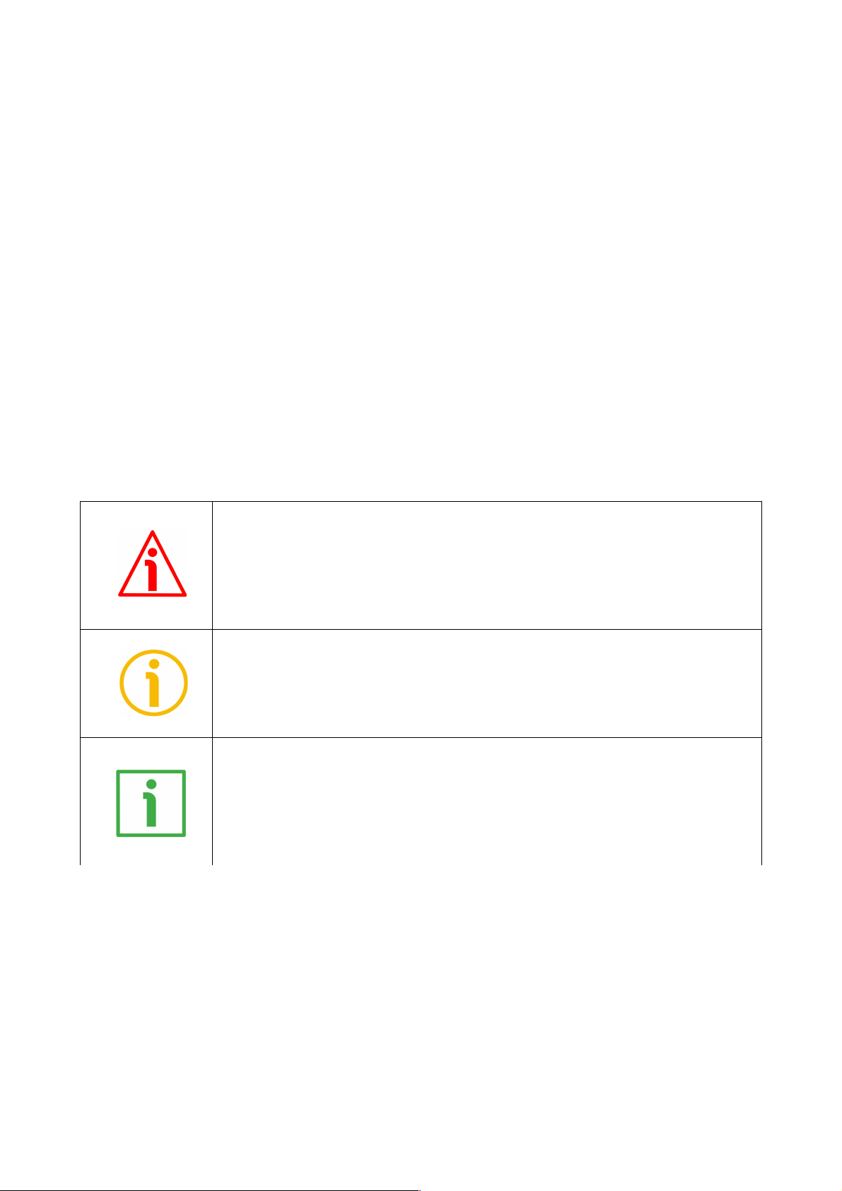
This icon, followed by the word WARNING, is meant to highlight the parts of the
text where information of great significance for the user can be found: user must
pay the greatest attention to them! Instructions must be followed strictly in order
to guarantee the safety of the user and a correct use of the device. Failure to heed
a warning or comply with instructions could lead to personal injury and/or damage
to the unit or other equipment.
This icon, followed by the word NOTE, is meant to highlight the parts of the text
where important notes needful for a correct and reliable use of the device can be
found. User must pay attention to them! Failure to comply with instructions could
cause the equipment to be set wrongly: hence a faulty and improper working of
the device could be the consequence.
This icon is meant to highlight the parts of the text where suggestions useful for
making it easier to set the device and optimize performance and reliability can be
found. Sometimes this symbol is followed by the word EXAMPLE when instructions
for setting parameters are accompanied by examples to clarify the explanation.
Page 6

Preliminary information
This guide is designed to provide the most complete and exhaustive information the operator needs to
correctly and safely install and operate the SMAX absolute linear encoder with SSI and analogue
interfaces.
This encoder is designed to measure linear displacements in industrial machines and automation systems.
The measurement system includes a magnetic tape and a magnetic sensor with conversion electronics.
The tape is magnetized with a coded sequence of North-South poles generating a pseudo-random
absolute pattern. As the sensor is moved along the magnetic tape, it detects the displacement and yields
the absolute position information through the SSI interface (SMAX-BG..., SMAX-GG...) or the voltage
(SMAX-AV2...) / current (SMAX-AI1...) analogue interface or the Modbus interface (SMAX-MB...). The
Modbus sensor is provided with its own technical documentation.
It is mandatory to pair the sensor with the MTAX type magnetic scale. The measuring length can be
200 mm / 7.874”, 300 mm / 11.811” and 600 mm / 23.622”, see the order code.
To make it easier to read and understand the text, this guide can be divided into three main sections.
In the first section some general information concerning the safety, the mechanical installation and the
electrical connection as well as tips for setting up and running properly and efficiently the unit are
provided.
In the second section, entitled SSI interface, both general and specific information is given on the SSI
interface.
In the third section, entitled Analogue interface, both general and specific information is given on the
analogue interface.
Page 7
SMAX - SSI and analogue
1 - Safety summary
1.1 Safety
• Always adhere to the professional safety and accident prevention
regulations applicable to your country during device installation and
operation;
• installation and maintenance operations have to be carried out by
qualified personnel only, with power supply disconnected and stationary
mechanical parts;
• device must be used only for the purpose appropriate to its design: use for
purposes other than those for which it has been designed could result in
serious personal and/or the environment damage;
• high current, voltage and moving mechanical parts can cause serious or
fatal injury;
• warning ! Do not use in explosive or flammable areas;
• failure to comply with these precautions or with specific warnings
elsewhere in this manual violates safety standards of design, manufacture,
and intended use of the equipment;
• Lika Electronic assumes no liability for the customer's failure to comply
with these requirements.
1.2 Electrical safety
• Turn OFF power supply before connecting the device;
• connect the unit according to the explanation in the ”Electrical
connections” section;
• connect Zero Setting and Counting direction inputs to 0Vdc, if not used;
- to zero set the encoder, connect Zero setting input to +Vdc for 100 µs at
least, then disconnect +Vdc; normally voltage must be at 0Vdc; zero set
must be performed after Counting direction setting; we suggest
performing the zero set when the encoder is in stop;
- Counting direction: increasing count (count up information) = connect
to 0Vdc; decreasing count (count down information) = connect to +Vdc;
• in compliance with 2014/30/EU norm on electromagnetic
compatibility, following precautions must be taken:
- before handling and installing the equipment, discharge
electrical charge from your body and tools which may come in touch
with the device;
- power supply must be stabilized without noise; install EMC filters on
device power supply if needed;
- always use shielded cables (twisted pair cables whenever possible);
- avoid cables runs longer than necessary;
- avoid running the signal cable near high voltage power cables;
- mount the device as far as possible from any capacitive or inductive
noise source; shield the device from noise source if needed;
- to guarantee a correct working of the device, avoid using strong magnets
on or near by the unit;
- minimize noise by connecting the shield and/or the connector housing
and/or the sensor to ground. Make sure that ground is not affected by
noise. The connection point to ground can be situated both on the device
MAN SMAX SSI_AI1_AV2 E 1.5.odt 1 - Safety summary 7 of 32
Page 8
SMAX - SSI and analogue
side and on user’s side. The best solution to minimize the interference
must be carried out by the user;
- do not stretch the cable; do not pull or carry by cable; do not use the
cable as a handle.
1.3 Mechanical safety
• Install the device following strictly the information in the “3 - Mounting
instructions” section;
• mechanical installation has to be carried out with stationary mechanical
parts;
• do not disassemble the unit;
• do not tool the unit;
• delicate electronic equipment: handle with care; do not subject the device
to knocks or shocks;
• protect the unit against acid solutions or chemicals that may damage it;
• respect the environmental characteristics of the product;
• we suggest installing the unit providing protection means against waste,
especially swarf as turnings, chips, or filings; should this not be possible,
please make sure that adequate cleaning measures (as for instance
brushes, scrapers, jets of compressed air, etc.) are in place in order to
prevent the sensor and the magnetic scale from jamming.
2 - Identification
Device can be identified through the order code and the serial number printed
on the label applied to its body. Information is listed in the delivery document
too. Please always quote the order code and the serial number when reaching
Lika Electronic for purchasing spare parts or needing assistance. For any
information on the technical characteristics of the product refer to the
technical datasheet.
Warning: devices having order code ending with "/Sxxx" may have
mechanical and electrical characteristics different from standard and
be supplied with additional documentation for special connections
(Technical Info).
MAN SMAX SSI_AI1_AV2 E 1.5.odt 2 - Identification 8 of 32
Page 9
SMAX - SSI and analogue
3 - Mounting instructions
WARNING
Installation has to be carried out by qualified personnel only, with power supply
disconnected and mechanical parts compulsorily in stop.
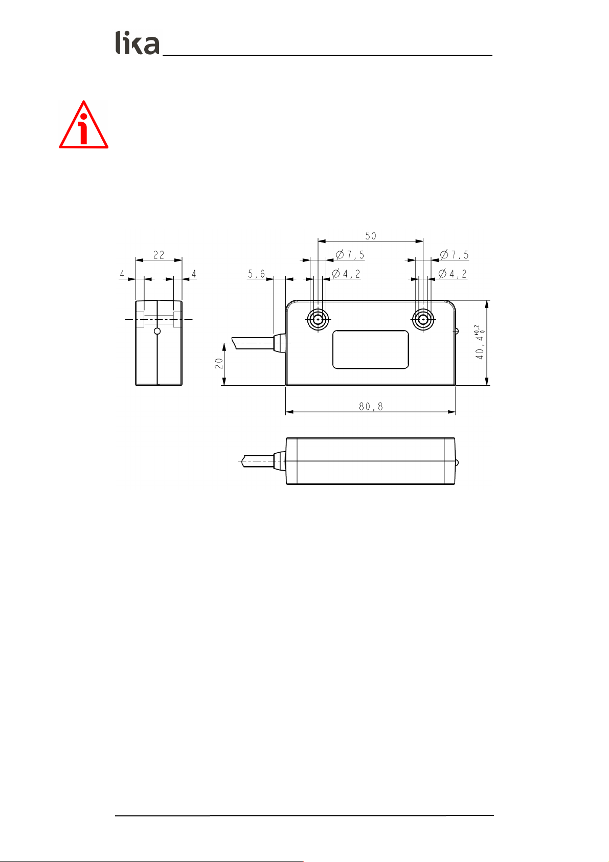
3.1 Overall dimensions
(values are expressed in mm)
3.2 Magnetic tape
The sensor has to be paired with the MTAX type magnetic tape only. For
detailed information on the MTAX type tape and how to mount it properly,
please refer to the specific technical documentation.
Install the unit providing protection means against waste, especially swarf as
turnings, chips or filings; should this not be possible, please make sure that
adequate cleaning measures (as for instance brushes, scrapers, jets of
compressed air, etc.) are in place in order to prevent the sensor and the
magnetic scale from jamming.
Make sure the mechanical installation meets the system's requirements of
distance, planarity and parallelism between the sensor and the scale indicated in
Figure 2 all along the whole measuring length.
MTAX magnetic scale can be provided with a cover strip to protect its magnetic
surface (see the order code).
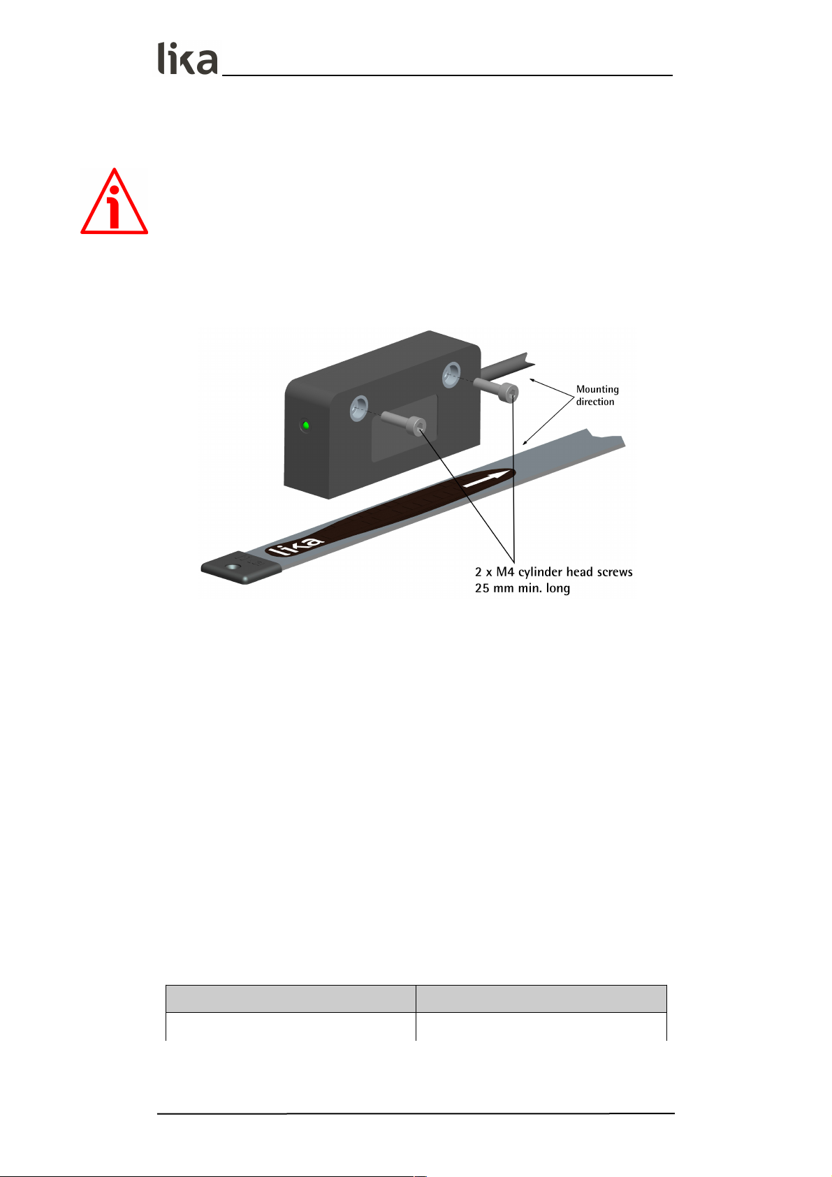
Figure 1 shows how the sensor and the scale must be installed; the arrow
indicates the standard counting direction (increasing count when the sensor
MAN SMAX SSI_AI1_AV2 E 1.5.odt 3 - Mounting instructions 9 of 32
Page 10
SMAX - SSI and analogue
moves in the direction indicated by the arrow; further information in the “4.1.6
Counting direction input” section on page 15).
WARNING
The system cannot operate if mounted otherwise than illustrated in Figure 1.
3.3 Mounting the sensor
Figure 1
Make sure the mechanical installation complies with the system requirements
concerning distance, planarity and parallelism between the sensor and the scale
as shown in Figure 2. Avoid contact between the parts. Fix the sensor by means
of two M4 25 mm min. long cylinder head screws inserted in the provided
holes. Recommended minimum bend radius of the cable: R 25 mm. Install
the sensor and the magnetic scale as shown in the Figure. The system does not
operate if mounted otherwise than illustrated in the Figure. The arrow is
intended to indicate the standard counting direction (count up information).
Please note that the MTAX magnetic scale can be provided with a cover strip to
protect its magnetic surface (see the order code). Therefore the distance
between the sensor and the magnetic scale is different whether the cover strip
is applied.
The distance D (see Figure 2) between the centre of the screw fixing
holes and the MTAX magnetic scale has to be as follows:
without cover strip with cover strip
31.7 mm 33.2 mm (1.248” 1.307”) 31.3 mm 32.8 mm (1.232” 1.291”)
For better operation the suggested distance D is 32.2 mm (1.267”).
MAN SMAX SSI_AI1_AV2 E 1.5.odt 3 - Mounting instructions 10 of 32
Page 11

SMAX - SSI and analogue
WARNING
Make sure the mechanical installation complies with the system requirements
concerning distance, planarity and parallelism between the sensor and the scale
as shown in Figure 2 all along the whole measuring length.
Figure 2
WARNING
After having installed the sensor on the magnetic scale a zero setting operation
is compulsorily required. The zero setting operation is further required every
time either the sensor or the scale is replaced. For any information on the zero
setting operation please refer to the “4.1.5 Zero setting input” section on page
14. The Zero setting function is not available for the analogue interface (SMAXAI1-..., SMAX-AV2-...).
MAN SMAX SSI_AI1_AV2 E 1.5.odt 3 - Mounting instructions 11 of 32
Page 12

SMAX - SSI and analogue
3.4 Measuring length
The maximum length of the tape L is between 280 mm / 11.023” and 680 mm
/ 26.771” (for further information refer the order code in the product
datasheet). As the sensor area has always to be fully within the limits of the
tape magnetic surface, then the maximum measuring length ML is the
maximum length of the tape minus the length of the sensor head = L – 80
mm / 3.149” (200 mm / 7.874” ÷ 600 mm / 23.622”).
3.5 Standard counting direction
The positive counting direction (count up information) is achieved when the
sensor moves on the tape according to the white arrow shown in Figure 1. For
further information see the “4.1.6 Counting direction input” section on page 15.
MAN SMAX SSI_AI1_AV2 E 1.5.odt 3 - Mounting instructions 12 of 32
Page 13

SMAX - SSI and analogue
4 - SSI interface
Order codes: SMAX-BG-…
SMAX-GG-…
4.1 SSI interface electrical connections
WARNING
Electrical connection has to be carried out by qualified personnel only, with
power supply disconnected and mechanical parts compulsorily in stop.
WARNING
If wires of unused signals come in contact, irreparable damage could be caused
to the device. Please insulate them singularly.
Function M8 cable M12 8-pin
0Vdc
Black 1
+10Vdc +30Vdc
Red 2
Clock IN +
Yellow 3
Clock IN -
Blue 4
Data OUT +
Green 5
Data OUT -
Orange 6
Zero setting
White 7
Counting direction
Grey 8
Shield
Shield Case
4.1.1 M8 cable specifications
Model : LIKA HI-FLEX sensor cable type M8
Wires : 2 x 0.22 mm2 + 6 x 0.14 mm2 (24/26 AWG)
Jacket : Matt Polyurethane (TPU) halogen free, oil, hydrolysis,
abrasion resistant
Shield : tinned copper braid, coverage 85%
Outer diameter : 5.3 mm ÷ 5.6 mm (0.209” ÷ 0.220”)
Min. bend radius : Ø x 7.5
Work temperature : -40°C +90°C (-40°F +194°F) – dynamic installation
-50°C +90°C (-58°F +194°F) – fixed installation
Conductor resistance : 90 /km / 148 /km
4.1.2 M12 8-pin connector
Male
Frontal side
A coding
MAN SMAX SSI_AI1_AV2 E 1.5.odt 4 - SSI interface 13 of 32
Page 14

SMAX - SSI and analogue
4.1.3 Connection of the shield
For signals transmission always use shielded cables. The cable shielding must be
connected properly to the metal ring nut of the connector in order to ensure a
good earthing through the frame of the device.
4.1.4 Ground connection
Minimize noise by connecting the shield and/or the connector housing and/or
the sensor to ground. Make sure that ground is not affected by noise. The
connection point to ground can be situated both on the device side and on
user’s side. The best solution to minimize the interference must be carried out by
the user.
4.1.5 Zero setting input
The output value can be set to zero (reset) via an external signal issued by a PLC
or other controller device. When the internal microprocessor receives the signal
it resets the output information. This can be very useful for setting the zero
position of both the sensor and the machine. To zero set the encoder position,
connect Zero setting input to +Vdc for 100 µs at least, then disconnect +Vdc;
normally voltage must be at 0Vdc; zero set must be performed after Counting
direction setting; we suggest performing the zero set when the encoder is in
stop. Connect to 0Vdc if not used.
WARNING
It is necessary to zero set the sensor after having set a new counting direction.
WARNING
After having installed the sensor on the magnetic tape a zero setting operation
is compulsorily required. The zero setting operation is further required every
time either the sensor or the tape is replaced.
NOTE
Please note that, after setting the zero point, the positive counting will be from
0 towards the max. value (see the table below); if you move the axis before the
0 point, the detected value will be the max. number of information – 1 down.
EXAMPLE
Let's suppose we are using the SMAX-GG-100-... model, it is paired with the
MTAX-680-... profile. If you set the 0 along the path, starting from the 0 point,
the output values will be from 0 towards the max. value (6,000, see the table
below) when the measuring system moves according to the arrow shown in
Figure 1; when the system moves back, the value immediately after 0 will be the
max. number of information – 1 (8,191).
... 8,190 8,191 0 1 2 ... 6,000
MAN SMAX SSI_AI1_AV2 E 1.5.odt 4 - SSI interface 14 of 32
Page 15

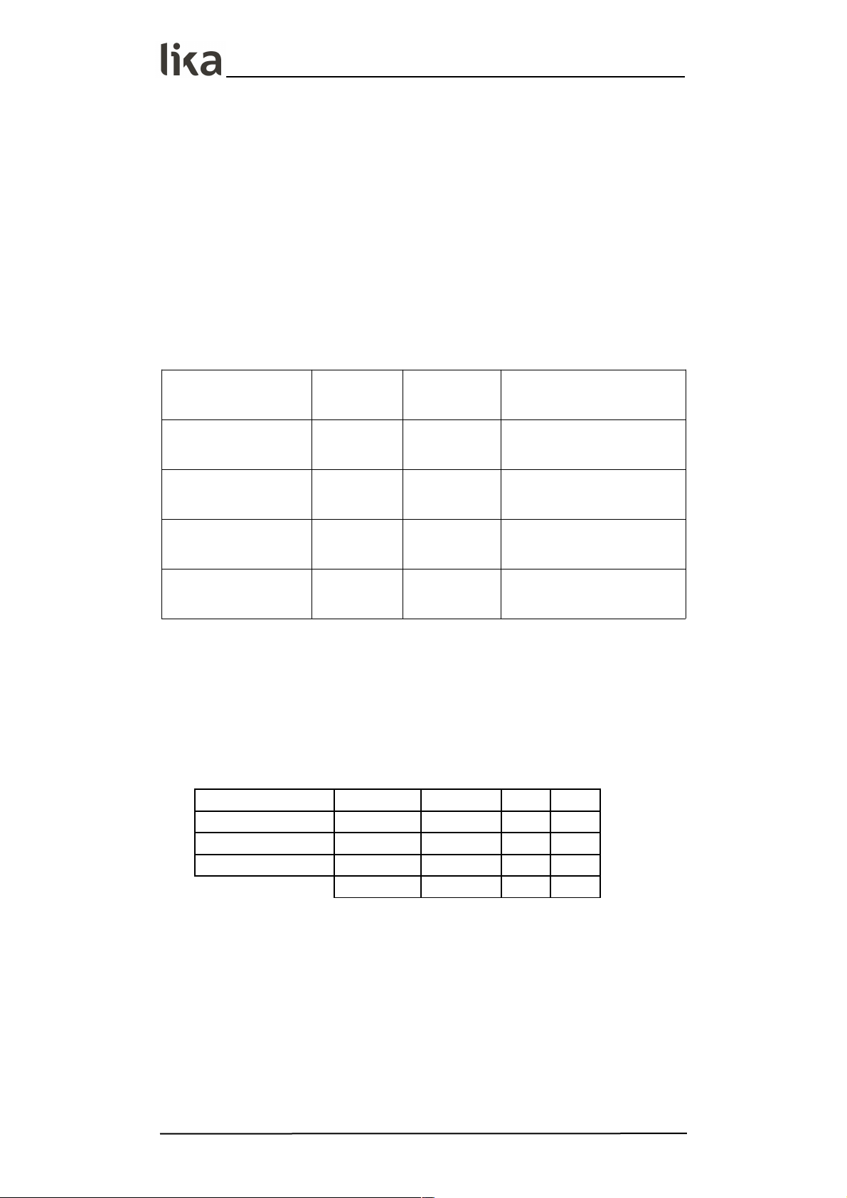
SMAX - SSI and analogue
Model Max. value
Max. number of
information
SMAX-xx-1250-... + MTAX-680
480 512 (9 bits)
SMAX-xx-1250-... + MTAX-380
240 256 (8 bits)
SMAX-xx-1250-... + MTAX-280
160 256 (8 bits)
SMAX-xx-1000-... + MTAX-680
600 1,024 (10 bits)
SMAX-xx-1000-... + MTAX-380
300 512 (9 bits)
SMAX-xx-1000-... + MTAX-280
200 512 (9 bits)
SMAX-xx-500-... + MTAX-680
1,200 2,048 (11 bits)
SMAX-xx-500-... + MTAX-380
600 1,024 (10 bits)
SMAX-xx-500-... + MTAX-280
400 1,024 (10 bits)
SMAX-xx-100-... + MTAX-680
6,000 8,192 (13 bits)
SMAX-xx-100-... + MTAX-380
3,000 4,096 (12 bits)
SMAX-xx-100-... + MTAX-280
2,000 2,048 (11 bits)
4.1.6 Counting direction input
The standard counting direction is to be intended with sensor moving as
indicated by the arrow in Figure 1. The counting direction circuit allows to
reverse the counting direction. In other words it allows the count up when the
sensor moves in reverse of the standard direction, i.e. in the opposite direction
to the one shown by the arrow in Figure 1. Connect the Counting direction
input to 0Vdc if not used. Connect the counting direction input to 0Vdc to have
an increasing count when the sensor moves as indicated by the arrow in Figure
1; connect the counting direction input to +Vdc to have an increasing count
when the sensor moves in reverse of the standard direction, i.e. in the opposite
direction to the one shown by the arrow in Figure 1.
WARNING
After having set the new counting direction it is necessary to zero set the
sensor.
4.2 SSI (Synchronous Serial Interface)
SSI (the acronym for Synchronous Serial
Interface) is a synchronous point-to-point serial
interface engineered for unidirectional data
transmission between one Master and one Slave.
Developed in the first eighties, it is based on the RS-
MAN SMAX SSI_AI1_AV2 E 1.5.odt 4 - SSI interface 15 of 32
Page 16

SMAX - SSI and analogue
422 serial standard. Its most peculiar feature is that data transmission is
achieved by synchronizing both the Master and the Slave devices to a common
clock signal generated by the controller; in this way the output information is
clocked out at each controller's request. Furthermore only two pairs of twisted
wires are used for data and clock signals, thus a six-wire cable is required.
The main advantages in comparison with parallel or asynchronous data
transmissions are:
• less conductors are required for transmission;
• less electronic components;
• possibility of insulting the circuits galvanically by means of
optocouplers;
• high data transmission frequency;
• hardware interface independent from the resolution of the absolute
encoder.
Furthermore the differential transmission increases the noise immunity and
decreases the noise emissions. It allows multiplexing from several encoders, thus
process controls are more reliable with simplified line design and easier data
management.
Data transmission is carried out as follows.
At the first falling edge of the clock signal (1, the logic level changes from high
to low) the absolute position value is stored while at the following rising edge
(2) the transmission of data information begins starting from the MSB.
At each change of the clock signal and at each subsequent rising edge (2) one
bit is clocked out at a time, up to LSB, so completing the data word
transmission. The cycle ends at the last rising edge of the clock signal (3). This
means that up to n + 1 rising edges of the clock signals are required for each
data word transmission (where n is the bit resolution); for instance, a 13-bit
encoder needs 14 clock edges. If the number of clocks is greater than the
number of bits of the data word, then the system will send a zero (low logic
level signal) at each additional clock, zeros will either lead (LSB ALIGNED
protocol) or follow (MSB ALIGNED protocol) or lead and/or follow (TREE FORMAT
protocol) the data word. After the period Tm monoflop time, having a typical
duration of 16 µsec, calculated from the end of the clock signal transmission,
the encoder is then ready for the next transmission and therefore the data
signal is switched high.
MAN SMAX SSI_AI1_AV2 E 1.5.odt 4 - SSI interface 16 of 32
Page 17
SMAX - SSI and analogue
The clock signal has a typical logic level of 5V, the same as the output signal
which has customarily a logic level of 5V in compliance with RS-422 standard.
The output code can be either Binary or Gray (see the order code).
4.2.1 MSB left aligned protocol
“MSB left aligned” protocol allows to left align the bits, beginning from MSB
(most significant bit) to LSB (least significant bit); LSB is then sent at the last
clock cycle. If the number of clock signals is higher than the data bits, then
unused bits are forced to logic level low (0) and follow the data word. This
protocol can be used in sensors having any resolution.
The word has a variable length according to resolution, as shown in the
following table.
Model Resolution
Length of
the word
Max. number of
information (max. value)
SMAX-BG-1250-...
SMAX-GG-1250-...
1.25 mm 9 bits 9 bits (511)
SMAX-BG-1000-...
SMAX-GG-1000-...
1.0 mm 10 bits 10 bits (1,023)
SMAX-BG-500-...
SMAX-GG-500-...
0.5 mm 11 bits 11 bits (2,047)
SMAX-BG-100-...
SMAX-GG-100-...
0.1 mm 13 bits 13 bits (8,191)
* When the profile is 680 mm / 26.771” long. See also the table on page 15
The output code of the sensor can be GRAY or BINARY (see the order code).
The length of each information is equal to the resolution.
Structure of the transmitted position value:
SMAX-xx-1250-... bit 9 … 1
SMAX-xx-1000-... bit 10 … 1
SMAX-xx-500-... bit 11 … 1
SMAX-xx-100-... bit 13 … 1
value
MSB … LSB
* When the profile is 680 mm / 26.771” long. See also the table on page 15
MAN SMAX SSI_AI1_AV2 E 1.5.odt 4 - SSI interface 17 of 32
Page 18

SMAX - SSI and analogue
WARNING
The position value issued by the sensor is expressed in pulses; to convert the
pulses into a metric measuring unit you must multiply the number of detected
pulses by the resolution.
EXAMPLE 1
SMAX-BG-500-…
resolution: 500 µm = 0.5 mm
detected pulses = 123
position value = 123 * 500 = 61,500 µm = 61.5 mm
EXAMPLE 2
SMAX-BG-100-…
resolution: 100 µm = 0.1 mm
detected pulses = 1569
position value = 1569 * 100 = 156,900 µm = 156.9 mm
4.2.2 Recommended transmission rates
The SSI interface has a frequency of data transmission ranging between 100 kHz
and 1.5 MHz.
The CLOCK signals and the DATA signals comply with the “EIA standard RS-422”.
The clock frequency (baud rate) depends on the length of the cable and must
comply with the technical information reported in the following table:
Cable length Baud rate
< 60 m < 400 kHz
< 100 m < 300 kHz
< 200 m < 200 kHz
< 400 m < 100 kHz
The time interval between two Clock sequence transmissions must be at least 16
µs ( Tp = pause time > 16 µs).
MAN SMAX SSI_AI1_AV2 E 1.5.odt 4 - SSI interface 18 of 32
Page 19

SMAX - SSI and analogue
4.3 Recommended SSI circuit
MAN SMAX SSI_AI1_AV2 E 1.5.odt 4 - SSI interface 19 of 32
Page 20

SMAX - SSI and analogue
5 - Analogue interface
Order codes: SMAX-AI1-… (4-20 mA)
SMAX-AV2-… (0-10 V)
5.1 Analogue interface electrical connections
WARNING
Electrical connection has to be carried out by qualified personnel only, with
power supply disconnected and mechanical parts compulsorily in stop.
WARNING
If wires of unused signals come in contact, irreparable damage could be caused
to the device. Please insulate them singularly.
Functions
M8 cable M12 8-pin
AI1 AV2
0Vdc Power Supply
Black 1
+13Vdc +30Vdc
Red 2
0Vdc analogue
Yellow 3
START
Blue 4
+Iout +Vout
Green 5
STOP
Orange 6
n. c.
White 7
FAULT n. c.
Grey 8
Shield
Shield Case
n. c. = not connected
5.1.1 M8 cable specifications
Model : LIKA HI-FLEX sensor cable type M8
Wires : 2 x 0.22 mm2 + 6 x 0.14 mm2 (24/26 AWG)
Jacket : Matt Polyurethane (TPU) halogen free, oil, hydrolysis,
abrasion resistant
Shield : tinned copper braid, coverage 85%
Outer diameter : 5.3 mm ÷ 5.6 mm (0.209” ÷ 0.220”)
Min. bend radius : Ø x 7.5
Work temperature : -40°C +90°C (-40°F +194°F) – dynamic installation
-50°C +90°C (-58°F +194°F) – fixed installation
Conductor resistance : 90 /km / 148 /km
MAN SMAX SSI_AI1_AV2 E 1.5.odt 5 - Analogue interface 20 of 32
Page 21

SMAX - SSI and analogue
5.1.2 M12 8-pin connector
Male, frontal side
A coding
5.1.3 Connection of the shield
For signals transmission always use shielded cables. The cable shielding must be
connected properly to the metal ring nut of the connector in order to ensure a
good earthing through the frame of the device.
5.1.4 Ground connection
Minimize noise by connecting the shield and/or the connector housing and/or
the sensor to ground. Make sure that ground is not affected by noise. The
connection point to ground can be situated both on the device side and on
user’s side. The best solution to minimize the interference must be carried out by
the user.
5.2 Signals description
5.2.1 0Vdc
0Vdc Power Supply and 0Vdc analogue are internally connected.
5.2.2 START input
It is used to execute the TEACH-IN procedure. It is active at HIGH logic level
(voltage greater than 10V must be applied). For any further information on
using the START and STOP inputs refer to the “5.3 TEACH-IN procedure”
section on page 24.
5.2.3 +Iout current analogue output
+Iout provides the current analogue signal.
AI1 output range is: min. quote = 4 mA, max. quote = 20 mA
The increment at each step is as follows:
10-bit DAC 4-20 mA: 16000/1024 = 15.625 µA
5.2.4 +Vout voltage analogue output
+Vout provides the voltage analogue signal.
AV2 output range is: min. quote = 0 V, max. quote = 10 V
The increment at each step is as follows:
10-bit DAC 0-10 V: 10000/1024 = 9.765 mV
MAN SMAX SSI_AI1_AV2 E 1.5.odt 5 - Analogue interface 21 of 32
Page 22

SMAX - SSI and analogue
5.2.5 STOP input
It is used to execute the TEACH-IN procedure. It is active at HIGH logic level
(voltage greater than 10V must be applied). For any further information on
using the START and STOP inputs refer to the “5.3 TEACH-IN procedure”
section on page 24.
5.2.6 Fault output
The Fault output is only available for AI1 current analogue output and is
intended to signal an error condition such as a circuit break.
To connect the Fault signal please refer to the examples in the sections
hereafter: “5.2.6.1 Fault output connected to a PLC input“ and “5.2.6.2 Fault
output connected to a relay“.
Please pay attention to the value of the R2 resistor (Figure 3 and Figure 4).
Imax = 50 mA
R1 = 47
R1
I
Vdc
R2
No encoder error = transistor ON (conducting)
Encoder error = transistor OFF (open)
5.2.6.1 Fault output connected to a PLC input
Figure 3
No encoder error = PLC input Low (0Vdc)
Encoder error = PLC input High (+Vdc)
MAN SMAX SSI_AI1_AV2 E 1.5.odt 5 - Analogue interface 22 of 32
Page 23

SMAX - SSI and analogue
EXAMPLE
Vdc = +24 V
R1 = 47
R1
I
Vdc
R2
I = 4.7 mA
R2 = 5 k
5.2.6.2 Fault output connected to a relay
Figure 4
No encoder error = coil energized
Encoder error = coil de-energized
EXAMPLE
Vdc = +24 V
R1 = 47
R1
I
Vdc
R2
I = 30 mA (current needed to energize a small relay coil)
R2 = 750
MAN SMAX SSI_AI1_AV2 E 1.5.odt 5 - Analogue interface 23 of 32
Page 24

SMAX - SSI and analogue
5.3 TEACH-IN procedure
The TEACH-IN function allows to easily and intuitively set by means of two
external signals both the furthermost points in the travel of an axis, then the
available analogue range will be scaled automatically within the set limits.
It allows to programme the encoder by considering directly the physical travel
of the application you need to measure and control.
The travel is defined in either an ascending or a descending ramp (see the “ 5.3.2
Ascending and descending ramp” section on page 26):
• with ascending ramp the initial position of the travel is the minimum
value of the output range and the final position is the maximum value
of the output range;
• with descending ramp the initial position of the travel is the maximum
value of the output range and the final position is the minimum value
of the output range;
• beyond the travel limits the current / voltage signal level is kept at the
minimum / maximum value of the selected range (4-20 mA for SMAXAI1-...; 0-10 V for SMAX-AV2-...).
The set output range (the overall information to be output) is defined over the
travel of the specific application and is comprised between the ends of the axis:
the origin of the axis, i.e. the point where you activate either the START or
the STOP input, and the end of the axis, i.e. the point where you activate the
START or the STOP input (see the “5.3.2 Ascending and descending ramp”
section on page 26). For the positions beyond the travel limits the current /
voltage signal level will be kept at the minimum / maximum value of the
selected range. With ascending ramp (see the Figure below), before the initial
position of the travel the encoder will provide the minimum current / voltage
signal level of the output range (4 mA for SMAX-AI1-...; 0 V for SMAX-AV2-...);
after the last position of the travel the encoder will provide the maximum
current / voltage signal level of the output range (20 mA for SMAX-AI1-...; 10 V
for SMAX-AV2-...).
MAN SMAX SSI_AI1_AV2 E 1.5.odt 5 - Analogue interface 24 of 32
Page 25

SMAX - SSI and analogue
On the contrary, with descending ramp, before the initial position of the travel
the encoder will provide the maximum current / voltage signal level of the
output range (20 mA for SMAX-AI1-...; 10 V for SMAX-AV2-...); after the last
position of the travel the encoder will provide the minimum current / voltage
signal level of the output range (4 mA for SMAX-AI1-...; 0 V for SMAX-AV2-...).
So for instance, if you have a SMAX-AV2-... sensor (its output range is 0-10 V)
and you program an ascending ramp, then the encoder will provide a fixed
voltage level of 0 V for the positions before the origin of the travel (i.e. the point
where you activate the START input); a voltage level increasing from 0 V
(origin of the travel, position 0) to 10 V (end of the travel) for the 1024 positions
of the axis; a fixed voltage level of 10 V for the positions after the last point of
the travel (i.e. the point where you activate the STOP input).
NOTE
For any further information on the START and STOP input signals refer to
the “5.2 Signals description” section on page 21.
5.3.1 TEACH-IN procedure
WARNING
It is mandatory to activate the START input first and then the STOP input.
To programme the encoder using the TEACH-IN procedure act as follows. The
steps to define a ramp with increasing output values are described hereinafter;
MAN SMAX SSI_AI1_AV2 E 1.5.odt 5 - Analogue interface 25 of 32
Page 26

SMAX - SSI and analogue
please refer to the following section for information on defining a ramp with
decreasing output values.
Move the axis to the origin of the physical travel of the application you
want to measure and control; in other words, move it to the point where
the travel starts;
switch the START input to HIGH logic level +Vdc for 3 seconds at least;
the LED in the sensor switches off; in this way you set the point where,
during normal operation, the encoder will provide the minimum current /
voltage signal level available in the output range (4 mA for SMAX-AI1-...; 0 V
for SMAX-AV2-...);
now move the axis to the end of the physical travel of the application you
want to measure and control; in other words, move it to the point where
the travel stops;
switch the STOP input to HIGH logic level +Vdc for 3 seconds at least;
the LED in the sensor switches on again; in this way you set the point
where, during normal operation, the encoder will provide the maximum
current / voltage signal level available in the output range (20 mA for
SMAX-AI1-...; 10 V for SMAX-AV2-...).
WARNING
If you set a wrong point for the initial position of the travel by activating the
START input, you have to turn off and then on again the power supply to
reset the sensor; then repeat the procedure from the first step.
Otherwise, if you set a wrong point for the final position of the travel by
activating the STOP input (this means that you have already set the initial
position of the travel by activating the START input), you have to switch the
STOP input to 0Vdc; then move the axis to the right final position and
activate the STOP input.
5.3.2 Ascending and descending ramp
NOTE
If you activate the START input
and then move forward the axis
according to the direction of the
travel before activating the STOP
input, you define an ascending ramp
as the one shown in the Figure on the
right. The minimum value of the
output range precedes the initial
point of the ramp (i.e. the beginning
of the axis travel); the maximum
value of the output range follows the
final point of the ramp (i.e. the end
limit of the axis travel).
MAN SMAX SSI_AI1_AV2 E 1.5.odt 5 - Analogue interface 26 of 32
Page 27

SMAX - SSI and analogue
NOTE
On the contrary, if you activate the
START input and then move
backward the axis in reverse of the
standard direction before activating
the STOP input (in other words
you activate the START input
when the axis is in the final position
of its travel and then activate the
STOP input when the axis is in the
first position of its travel), you define
a descending ramp as the one shown
in the Figure on the right. The
maximum value of the output range
precedes the initial point of the ramp
(i.e. the beginning of the axis travel);
the minimum value of the output
range follows the final point of the
ramp (i.e. the end limit of the axis
travel).
5.4 Recommended current analogue output circuit
5.5 Recommended voltage analogue output circuit
MAN SMAX SSI_AI1_AV2 E 1.5.odt 5 - Analogue interface 27 of 32
Page 28
SMAX - SSI and analogue
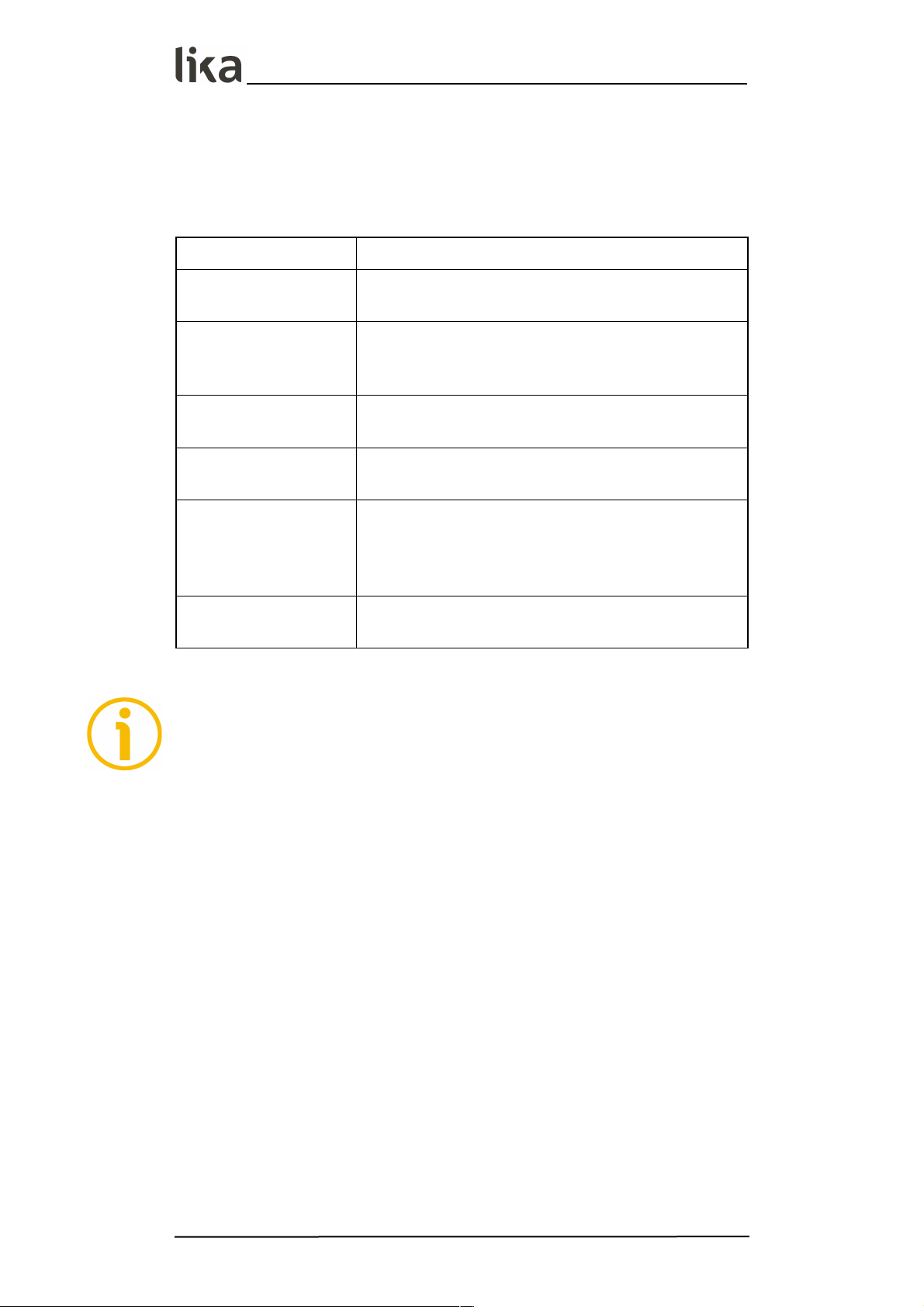
6 - Diagnostic LED
A LED is installed in the front side of the sensor and is designed to show visually
the operating or fault status of the device, as explained in the following table.
LED Description
ON
The sensor is running properly, there are no active
errors
Blinking at high
frequency (100 ms ON /
100 ms OFF)
Machine data parameters error
Blinking slowly (500 ms
ON / 500 ms OFF)
Flash memory error
Blinking very slowly (1 s
ON / 1 s OFF)
Error of the Hall sensors while reading the magnetic
scale
Single flash (200 ms ON
/ 1 s OFF)
The sensor is installed too far from the magnetic
scale, the installation does not comply with the
tolerance values between the sensor and the scale
(see Figure 2)
Double flash (200 ms
ON twice / 1 s OFF)
Several errors are active in the same time
NOTE
When you execute the TEACH-IN procedure (this function is available only for
SMAX with analogue interface -AI1-, -AV2-), as soon as you activate the START
input the LED switches off; as soon as you activate the STOP input it
switches on again. For any further information see the “5.3 TEACH-IN
procedure” section on page 24.
For further information refer also to the “8 - Troubleshooting” section on page
30.
MAN SMAX SSI_AI1_AV2 E 1.5.odt 6 - Diagnostic LED 28 of 32
Page 29

SMAX - SSI and analogue
7 - Maintenance
WARNING
Maintenance has to be carried out by qualified personnel only, with power
supply disconnected and mechanical parts compulsorily in stop.
The magnetic measurement system does not need any special maintenance;
anyway it has to be handled with the utmost care as any delicate electronic
equipment. From time to time we recommend the following operations:
periodically check the soundness of the structure and make sure that there
are no loose screws; tighten them if necessary;
check the gap between the sensor and the magnetic scale all along the
whole measuring length. Wear of the machine may increase the tolerances;
the surface of the magnetic scale has to be regularly cleaned using a soft
and clean cloth to remove dust, chips, moisture etc.
MAN SMAX SSI_AI1_AV2 E 1.5.odt 7 - Maintenance 29 of 32
Page 30

SMAX - SSI and analogue
8 - Troubleshooting
The following list shows some typical faults that may occur during installation
and operation of the magnetic measurement system.
Fault:
The system does not work (no pulse output).
Possible cause:
The scale and/or the sensor are not installed properly (the active surface of
the scale does not match the sensitive part of the sensor; or the sensor is
not oriented properly). For correct installation please refer to the “3 Mounting instructions” section on page 9.
A magnetic part or a protection surface is interposed between the sensor
and the scale. Only non-magnetic materials are allowed between the sensor
and the scale.
Installation does not comply with the tolerance gap between the sensor and
the scale indicated in this guide; the sensor hits the surface of the scale or is
too far from it. Check whether the sensor sensitive part is damaged.
The sensor has been damaged by short circuit or wrong connection.
Fault:
The measured values are either inaccurate or not provided in the whole length.
Possible cause:
The gap between the sensor and the scale is not respected all along the
whole measuring length. See the “3 - Mounting instructions” section on
page 9.
The sensor is not installed properly on the scale. See the “3 - Mounting
instructions” section on page 9.
The connection cable runs near high voltage cables or the shield is not
connected properly. Check the earthing point.
The frequency of Master clock is set too high or too low and the
transmission cannot be synchronized correctly. See the “4 - SSI interface”
section on page 13.
A section of the magnetic scale has been damaged mechanically or
magnetically along the measuring length.
The measuring error is caused by a torsion in the machine structure. Check
parallelism and symmetry in the movement of the machine.
MAN SMAX SSI_AI1_AV2 E 1.5.odt 8 - Troubleshooting 30 of 32
Page 31

This page intentionally left blank
Page 32

Document release Release date Description HW SW
Installation
file version
1.0 20.02.2014 1st issue - - -
1.1 08.04.2014 “4 - SSI interface” section updated - - -
1.2 17.07.2014 “4 - SSI interface” section updated - - -
1.3 12.01.2015 “3 - Mounting instructions” section updated - - -
1.4 19.11.2015 General review, mounting tolerances correction - - -
1.5 20.03.2017
General review, “3 - Mounting instructions” section
updated
- - -
Lika Electronic
Via S. Lorenzo, 25 • 36010 Carrè (VI) • Italy
Tel. +39 0445 806600
Fax +39 0445 806699
info@lika.biz • www.lika.biz
 Loading...