

Page 1
User's guide
RD4
Position measurement & control
Page 2

This publication was produced by Lika Electronic s.r.l. 2015. All rights reserved. Tutti i diritti riservati. Alle Rechte vorbehalten. Todos los
derechos reservados. Tous droits réservés.
This document and information contained herein are the property of Lika Electronic s.r.l. and shall not be reproduced in whole or in
part without prior written approval of Lika Electronic s.r.l. Translation, reproduction and total or partial modification (photostat copies,
film and microfilm included and any other means) are forbidden without written authorisation of Lika Electronic s.r.l.
The information herein is subject to change without notice and should not be construed as a commitment by Lika Electronic s.r.l. Lika
Electronic s.r.l. reserves the right to make all modifications at any moments and without forewarning.
This manual is periodically reviewed and revised. As required we suggest checking if a new or updated edition of this document is
available at Lika Electronic s.r.l.'s website. Lika Electronic s.r.l. assumes no responsibility for any errors or omissions in this document.
Critical evaluation of this manual by the user is welcomed. Your comments assist us in preparation of future documentation, in order
to make it as clear and complete as possible. Please send an e-mail to the following address info@lika.it for submitting your
comments, suggestions and criticisms.
Page 3

General contents
User's guide...............................................................................................................................................................................................1
General contents................................................................................................................................................................................3
Subject Index.......................................................................................................................................................................................7
Typographic and iconographic conventions..........................................................................................................................9
Preliminary information...............................................................................................................................................................10
1 Safety summary.................................................................................................................................. 11
1.1 Safety..........................................................................................................................................................................11
1.2 Electrical safety......................................................................................................................................................11
1.3 Mechanical safety..................................................................................................................................................12
2 Identification....................................................................................................................................... 13
3 Mechanical installation.....................................................................................................................14
4 Electrical connections........................................................................................................................ 17
4.1 Ground connection (Figure 3)..........................................................................................................................17
4.2 Connectors (Figure 3)...........................................................................................................................................18
4.3 Diagnostic LEDs (Figure 3).................................................................................................................................20
4.4 Dip-Switches (Figure 4).......................................................................................................................................21
4.4.1 Setting the node address: Node ID (Figure 4)...................................................................................22
4.4.2 Setting the data transmission rate: Baud rate (Figure 4)............................................................23
4.4.3 RT bus termination (Figure 4)...................................................................................................................23
5 Quick reference................................................................................................................................... 24
6 Functions.............................................................................................................................................. 25
6.1 Working principle..................................................................................................................................................25
6.2 Movements: jog and positioning....................................................................................................................26
6.3 Digital inputs and outputs.................................................................................................................................27
6.4 Objects 3120-00 Distance per revolution, 3114-00 Jog speed, 3115-00 Work speed, 3300-
00 Preset and 310F Delta space.........................................................................................................................28
7 CANopen® interface........................................................................................................................... 32
7.1 EDS files.....................................................................................................................................................................32
7.2 NMT states................................................................................................................................................................33
7.2.1 Initialization.....................................................................................................................................................33
7.2.2 Pre-operational state...................................................................................................................................34
7.2.3 Operational state...........................................................................................................................................34
7.2.4 Stopped state..................................................................................................................................................34
7.3 Communication messages.................................................................................................................................35
7.3.1 Generic pre-defined connection set.....................................................................................................36
7.4 NMT messages.........................................................................................................................................................36
7.6 PDO messages.........................................................................................................................................................37
7.6.1 “RECEIVE PDO1” message sent by the Master to the Slave........................................................38
Control Word............................................................................................................................................................................38
Jog +........................................................................................................................................................................................38
Jog -.........................................................................................................................................................................................38
Stop..........................................................................................................................................................................................39
Alarm reset...........................................................................................................................................................................39
Incremental jog..................................................................................................................................................................39
Start.........................................................................................................................................................................................39
Emergency............................................................................................................................................................................39
Page 4

Axis torque............................................................................................................................................................................40
OUT 1.......................................................................................................................................................................................40
OUT 2.......................................................................................................................................................................................40
OUT 3.......................................................................................................................................................................................40
Target position.........................................................................................................................................................................41
7.6.2 “TRANSMIT PDO1” message sent by the Slave to the Master....................................................42
Status word...............................................................................................................................................................................42
Axis in position....................................................................................................................................................................42
Axis enabled.........................................................................................................................................................................42
SW limit switch +..............................................................................................................................................................42
SW limit switch -...............................................................................................................................................................42
Alarm.......................................................................................................................................................................................42
Axis running.........................................................................................................................................................................42
Executing a command.....................................................................................................................................................42
Target position reached..................................................................................................................................................43
DAC Saturation...................................................................................................................................................................43
IN 1...........................................................................................................................................................................................43
IN 2...........................................................................................................................................................................................43
IN 3...........................................................................................................................................................................................43
Current velocity......................................................................................................................................................................43
Current position......................................................................................................................................................................43
7.7 SDO messages.........................................................................................................................................................45
7.7.1 Command.........................................................................................................................................................45
8 Programming parameters................................................................................................................. 46
8.1 Objects dictionary..................................................................................................................................................46
8.1.1 Standard objects (DS 301).........................................................................................................................46
1000-00 Device type............................................................................................................................................................46
1001-00 Error register.........................................................................................................................................................46
1003 Pre-defined Error Field.............................................................................................................................................47
1005-00 COB-ID SYNC messages....................................................................................................................................47
1008-00 Device name..........................................................................................................................................................47
1009-00 Hardware Version................................................................................................................................................47
100A-00 Software Version.................................................................................................................................................47
100C-00 Guard Time............................................................................................................................................................47
100D-00 Life Time Factor...................................................................................................................................................48
1010-01 Save Parameters..................................................................................................................................................48
1011-01 Restore Default Parameters...........................................................................................................................48
1014-00 COB-ID EMCY........................................................................................................................................................49
1015-00 Inhibit Time Emergency....................................................................................................................................49
1018 Identity Object.............................................................................................................................................................49
1400 Receive PDO Communication Parameter 1.....................................................................................................50
1600 Receive PDO Mapping Parameter 1...................................................................................................................51
1800 Transmit PDO Communication Parameter 1..................................................................................................51
1A00 TPDO Mapping Parameter 1..................................................................................................................................53
8.1.2 Manufacturer's specific objects.............................................................................................................55
3000-00 Baud rate................................................................................................................................................................55
3001-00 Node ID....................................................................................................................................................................55
Device profile objects..............................................................................................................................................56
3108-00 Acceleration...........................................................................................................................................................56
3109-00 Deceleration..........................................................................................................................................................56
310C-00 Max following error...........................................................................................................................................56
Page 5

310D-00 Position window.................................................................................................................................................56
310E-00 Position window time.......................................................................................................................................56
310F Delta space.....................................................................................................................................................................57
3111-00 Kp position loop...................................................................................................................................................57
3112-00 Ki position loop....................................................................................................................................................58
3114-00 Jog speed................................................................................................................................................................58
3115-00 Work speed............................................................................................................................................................58
3116-00 Max speed..............................................................................................................................................................59
3117-00 Jog step length.....................................................................................................................................................59
3118-00 Start Torque current time................................................................................................................................59
3120-00 Distance per revolution....................................................................................................................................59
3300-00 Preset........................................................................................................................................................................60
3301-00 Offset........................................................................................................................................................................60
3302-00 Code sequence.....................................................................................................................................................61
3330-00 Kp current loop....................................................................................................................................................61
3331-00 Ki current loop......................................................................................................................................................61
3340-00 Max current...........................................................................................................................................................61
3341-00 Starting Torque current....................................................................................................................................62
3342-00 Gear ratio................................................................................................................................................................62
3343-00 Positive absolute limit switch........................................................................................................................62
3344-00 Negative absolute limit switch......................................................................................................................62
3005-00 Current value [mA].............................................................................................................................................63
3006-00 Temperature value..............................................................................................................................................63
3100-00 Control word.........................................................................................................................................................63
3101-00 Status word...........................................................................................................................................................63
3102-00 Demanded position value................................................................................................................................63
3103-00 Current position value......................................................................................................................................63
3105-00 Current velocity value.......................................................................................................................................64
3106-00 Target position.....................................................................................................................................................64
3107-00 Target speed..........................................................................................................................................................64
310B-00 Position following error...................................................................................................................................64
3110-00 Cyclic Time.............................................................................................................................................................64
3200-00 Alarms......................................................................................................................................................................65
Machine data not valid...................................................................................................................................................65
Flash memory error...........................................................................................................................................................65
Following error....................................................................................................................................................................65
Axis not synchronized......................................................................................................................................................65
Target not valid...................................................................................................................................................................65
Emergency............................................................................................................................................................................65
Overcurrent..........................................................................................................................................................................65
Overtemperature................................................................................................................................................................66
Undervoltage.......................................................................................................................................................................66
CAN Life guard error........................................................................................................................................................66
8.2 Warning messages................................................................................................................................................67
8.3 Emergency messages...........................................................................................................................................67
No active errors..................................................................................................................................................................67
Generic error........................................................................................................................................................................67
Power surge.........................................................................................................................................................................67
Overvoltage..........................................................................................................................................................................67
Undervoltage.......................................................................................................................................................................67
Overtemperature................................................................................................................................................................67
Page 6

Flash memory......................................................................................................................................................................67
Life Guard..............................................................................................................................................................................67
Following error....................................................................................................................................................................67
8.4 Node guarding protocol.....................................................................................................................................68
9 Programming examples..................................................................................................................... 69
10 Default parameters list................................................................................................................... 70
Page 7

Subject Index
1
1000-00 Device type......................................................46
1001-00 Error register...................................................46
1003 Pre-defined Error Field.......................................47
1005-00 COB-ID SYNC messages.............................47
1008-00 Device name....................................................47
1009-00 Hardware Version.........................................47
100A-00 Software Version..........................................47
100C-00 Guard Time......................................................47
100D-00 Life Time Factor.............................................48
1010-01 Save Parameters............................................48
1011-01 Restore Default Parameters.....................48
1014-00 COB-ID EMCY.................................................49
1015-00 Inhibit Time Emergency.............................49
1018 Identity Object.......................................................49
1400 Receive PDO Communication Parameter 1
.............................................................................................50
1600 Receive PDO Mapping Parameter 1.............51
1800 Transmit PDO Communication Parameter 1
.............................................................................................51
1A00 TPDO Mapping Parameter 1............................53
3
3000-00 Baud rate..........................................................55
3001-00 Node ID.............................................................55
3005-00 Current value [mA].......................................63
3006-00 Temperature value........................................63
3100-00 Control word...................................................63
3101-00 Status word.....................................................63
3102-00 Demanded position value.........................63
3103-00 Current position value................................63
3105-00 Current velocity value.................................64
3106-00 Target position...............................................64
3107-00 Target speed....................................................64
3108-00 Acceleration....................................................56
3109-00 Deceleration....................................................56
310B-00 Position following error.............................64
310C-00 Max following error.....................................56
310D-00 Position window...........................................56
310E-00 Position window time.................................56
310F Delta space..............................................................57
3110-00 Cyclic Time.......................................................64
3111-00 Kp position loop............................................57
3112-00 Ki position loop..............................................58
3114-00 Jog speed..........................................................58
3115-00 Work speed......................................................58
3116-00 Max speed........................................................59
3117-00 Jog step length..............................................59
3118-00 Start Torque current time.........................59
3120-00 Distance per revolution..............................59
3200-00 Alarms................................................................65
3300-00 Preset.................................................................60
3301-00 Offset..................................................................60
3302-00 Code sequence...............................................61
3330-00 Kp current loop..............................................61
3331-00 Ki current loop...............................................61
3340-00 Max current.....................................................61
3341-00 Starting Torque current.............................62
3342-00 Gear ratio.........................................................62
3343-00 Positive absolute limit switch..................62
3344-00 Negative absolute limit switch...............62
A
Alarm.....................................................................................42
Alarm reset..........................................................................39
Axis enabled.......................................................................42
Axis in position..................................................................42
Axis not synchronized....................................................65
Axis running.......................................................................42
Axis torque..........................................................................40
C
CAN Life guard error.......................................................66
Control Word.....................................................................38
Current position...............................................................43
Current velocity................................................................43
D
DAC Saturation.................................................................43
E
Emergency...................................................................39, 65
Executing a command...................................................42
F
Flash memory.....................................................................67
Flash memory error.........................................................65
Following error..........................................................65, 67
G
Generic error......................................................................67
I
IN 1.........................................................................................43
IN 2.........................................................................................43
IN 3.........................................................................................43
Incremental jog.................................................................39
J
Jog -.......................................................................................38
Jog +......................................................................................38
Page 8

L
Life Guard............................................................................67
M
Machine data not valid.................................................65
N
No active errors................................................................67
O
OUT 1.....................................................................................40
OUT 2.....................................................................................40
OUT 3.....................................................................................40
Overcurrent.........................................................................65
Overtemperature.................................................66 e seg.
Overvoltage........................................................................67
P
Power surge........................................................................67
S
Start.......................................................................................39
Status word........................................................................42
Stop........................................................................................39
SW limit switch -.............................................................42
SW limit switch +............................................................42
T
Target not valid.................................................................65
Target position..................................................................41
Target position reached.................................................43
U
Undervoltage........................................................66 e seg.
Page 9
Typographic and iconographic conventions
In this guide, to make it easier to understand and read the text the following typographic and
iconographic conventions are used:
• parameters and objects both of Lika device and interface are coloured in ORANGE;
• alarms are coloured in RED;
• states are coloured in FUCSIA.
When scrolling through the text some icons can be found on the side of the page: they are expressly
designed to highlight the parts of the text which are of great interest and significance for the user.
Sometimes they are used to warn against dangers or potential sources of danger arising from the use of
the device. You are advised to follow strictly the instructions given in this guide in order to guarantee
the safety of the user and ensure the performance of the device. In this guide the following symbols are
used:
This icon, followed by the word WARNING, is meant to highlight the parts of the
text where information of great significance for the user can be found: user must
pay the greatest attention to them! Instructions must be followed strictly in order
to guarantee the safety of the user and a correct use of the device. Failure to heed
a warning or comply with instructions could lead to personal injury and/or damage
to the unit or other equipment.
This icon, followed by the word NOTE, is meant to highlight the parts of the text
where important notes needful for a correct and reliable use of the device can be
found. User must pay attention to them! Failure to comply with instructions could
cause the equipment to be set wrongly: hence a faulty and improper working of
the device could be the consequence.
This icon is meant to highlight the parts of the text where suggestions useful for
making it easier to set the device and optimize performance and reliability can be
found. Sometimes this symbol is followed by the word EXAMPLE when instructions
for setting parameters are accompanied by examples to clarify the explanation.
Page 10

Preliminary information
This guide is designed to provide the most complete information the operator needs to correctly and
safely install and operate the ROTADRIVE positioning units RD4 model.
RD4 units are positioning devices which integrate into one system a brushless motor fitted with gearbox,
a drive, a multiturn absolute encoder and a position controller. They can be used in a variety of
applications in any industrial sector and are suitable to drive secondary axes such as in mold changers,
mobile stops, tools changers, suction cups motion units, conveyor and spindle positioning devices on
packaging & woodworking machineries, among others.
The available interfaces for fieldbus communication are: Modbus RTU, Profibus-DP and CANopen DS
301.
To make it easier to read the text, this guide can be divided into two main sections.
In the first section general information concerning the safety, the mechanical installation and the
electrical connection as well as tips for setting up and running properly and efficiently the unit are
provided.
While in the second section, entitled CANopen Interface, both general and specific information is given
on the CANopen interface. In this section the interface features and the parameters implemented in the
unit are fully described.
Page 11

RD4 CANopen®
1 Safety summary
1.1 Safety
• Always adhere to the professional safety and accident prevention
regulations applicable to your country during device installation and
operation;
• installation and maintenance operations have to be carried out by
qualified personnel only, with power supply disconnected and stationary
mechanical parts;
• device must be used only for the purpose appropriate to its design: use for
purposes other than those for which it has been designed could result in
serious personal and/or the environment damage;
• high current, voltage and moving mechanical parts can cause serious or
fatal injury;
• warning ! Do not use in explosive or flammable areas;
• failure to comply with these precautions or with specific warnings
elsewhere in this manual violates safety standards of design, manufacture,
and intended use of the equipment;
• Lika Electronic s.r.l. assumes no liability for the customer's failure to
comply with these requirements.
1.2 Electrical safety
• Turn OFF power supply before connecting the device;
• connect according to explanation in section ”Electrical connections”;
• a safety push-button for emergency power off has to be installed to shut
off motor power supply in case of emergency situations;
• in compliance with 2004/108/EC norm on electromagnetic
compatibility, following precautions must be taken:
- before handling and installing the equipment, discharge
electrical charge from your body and tools which may come in touch
with the device;
- power supply must be stabilized without noise; install EMC filters on
device power supply if needed;
- always use shielded cables (twisted pair cables whenever possible);
- avoid cables runs longer than necessary;
- avoid running the signal cable near high voltage power cables;
- mount the device as far as possible from any capacitive or inductive
noise source; shield the device from noise source if needed;
- to guarantee a correct working of the device, avoid using strong magnets
on or near by the unit;
MAN RD4 CB E 1.5 Safety summary 11 of 72
Page 12

RD4 CANopen®
- minimize noise by connecting the shield and/or the connector housing
and/or the frame to ground. Make sure that ground is not affected by
noise. The connection point to ground can be situated both on the device
side and on user’s side. The best solution to minimize the interference
must be carried out by the user.
1.3 Mechanical safety
• Install the device following strictly the information in the section
“Mounting instructions”;
• mechanical installation has to be carried out with stationary mechanical
parts;
• do not disassemble the unit;
• do not tool the unit or its shaft;
• delicate electronic equipment: handle with care; do not subject the device
and the shaft to knocks or shocks;
• respect the environmental characteristics of the product;
• unit with solid shaft: in order to guarantee maximum reliability over time
of mechanical parts, we recommend a flexible coupling to be installed to
connect ROTADRIVE and user's shaft; make sure the misalignment
tolerances of the flexible coupling are respected;
• unit with hollow shaft: ROTADRIVE can be mounted directly on a shaft
whose diameter has to respect the technical characteristics specified in the
purchase order and clamped by means of the collar and the hole into
which an anti-rotation pin has to be inserted.
WARNING
The unit has been adjusted by performing a no-load mechanical running test;
thence default values which has been set refer to an idle device, i.e. running
disengaged from the load. Furthermore they are intended to ensure a standard
and safe operation which not necessarily results in smooth running and
optimum performance. Thus to suit the specific application requirements it may
be advisable and even necessary to enter new parameters instead of the factory
default settings; in particular it may be necessary to change velocity,
acceleration, deceleration and gain values.
WARNING
The counter-electromotive force (back EMF) generated by the motor in case the
shaft is forced to rotate due to a manual external force can cause irreparable
damages to the internal circuitry.
MAN RD4 CB E 1.5 Safety summary 12 of 72
Page 13

RD4 CANopen®
2 Identification
Device can be identified through the ordering code and the serial number
printed on the label applied to its body. Information is listed in the delivery
document too. Please always quote the ordering code and the serial number
when reaching Lika Electronic s.r.l. for purchasing spare parts or needing
assistance. For any information on the technical characteristics of the product
refer to the technical catalogue.
MAN RD4 CB E 1.5 Identification 13 of 72
Page 14
RD4 CANopen®
3 Mechanical installation
WARNING
Installation and maintenance operations have to be carried out by qualified
personnel only, with power supply disconnected. Motor and shaft must be in
stop.
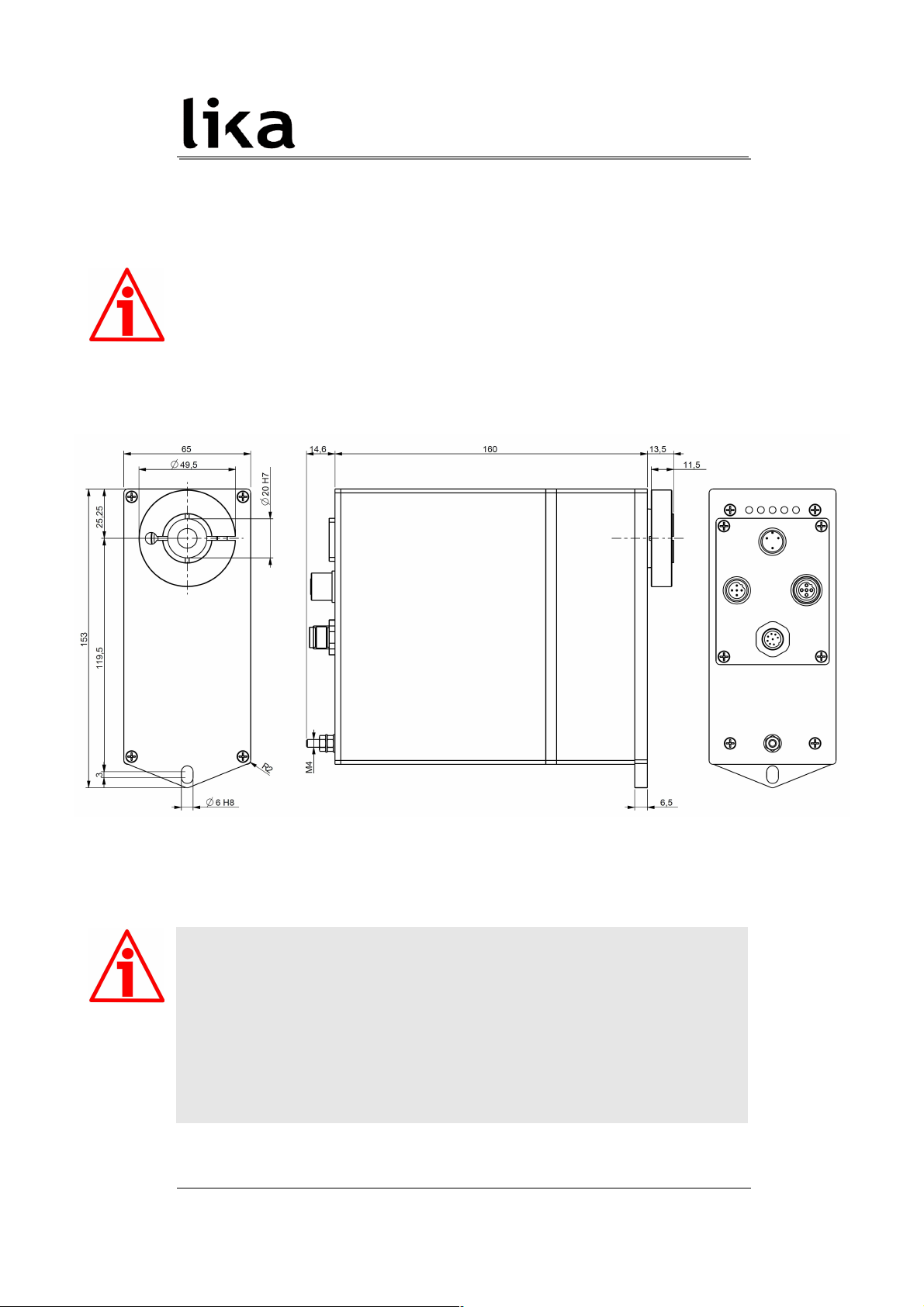
Figure 1 - RD4 unit – Overall dimensions
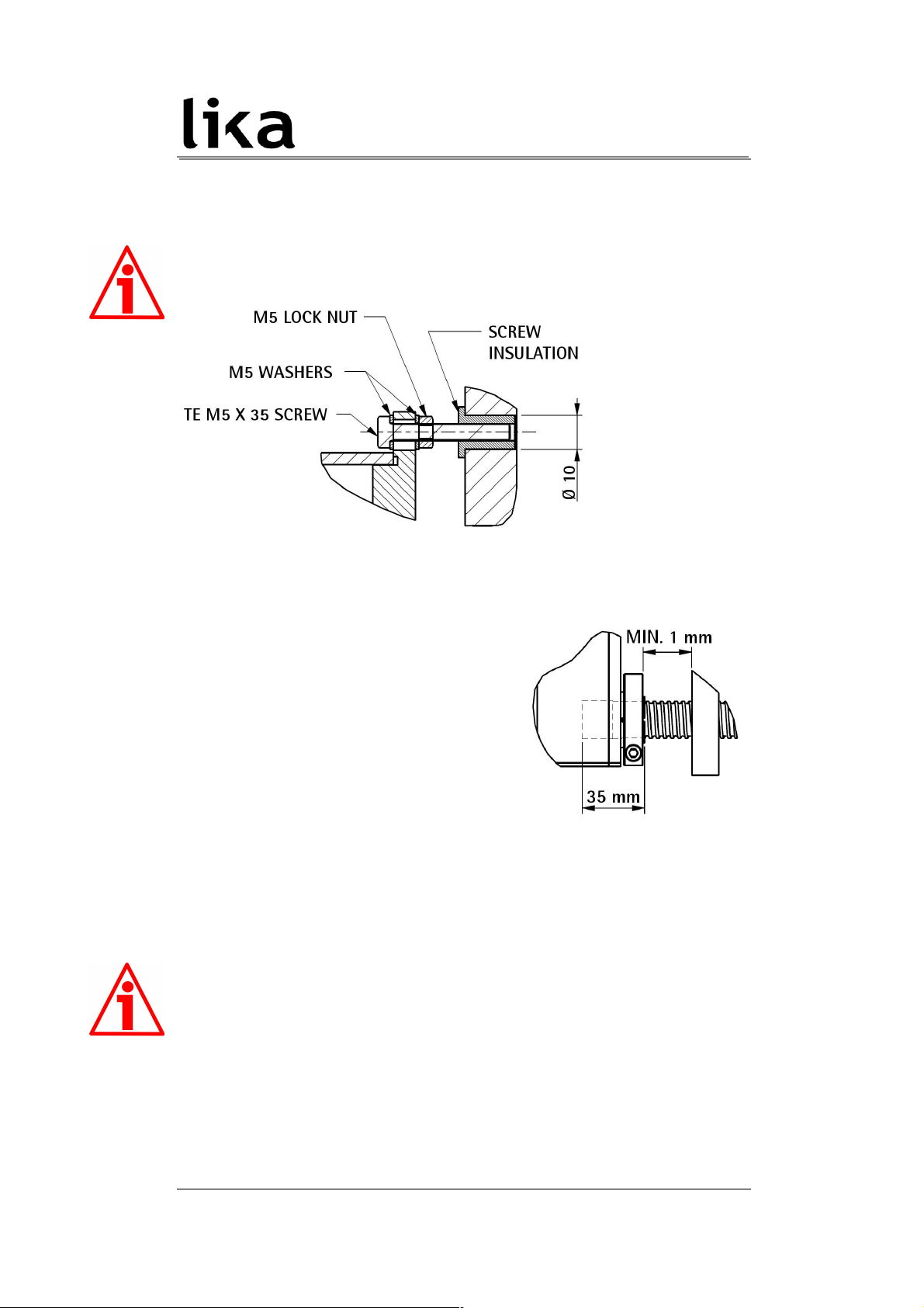
ROTADRIVE unit must be secured firmly only to the user's shaft using the
provided collar. ROTADRIVE unit is supplied with a screw insulation and an antirotation pin; the anti-rotation pin (TE M5 screw) has to be inserted into the
screw insulation. This will provide to the unit both stability and the mobility
needed to absorb the mechanical tensions produced during operation. Do not
fasten firmly the anti-rotation pin to the flange or the fixed support on user's
side without using the screw insulation! If this occurs, the mechanical tensions
would be transmitted completely to the motor shaft and this would lead to
bearings damages and mechanical breakdowns!
MAN RD4 CB E 1.5 Mechanical installation 14 of 72
Page 15
RD4 CANopen®
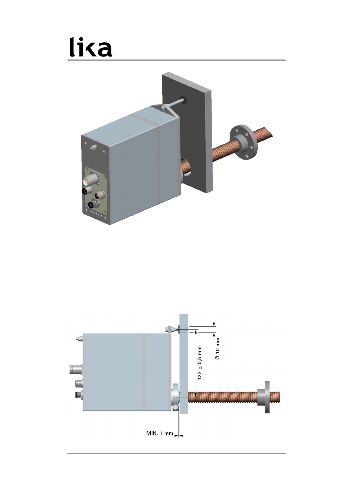
Figure 2 - Typical installation example of RD4 unit on worm screw
To install properly the ROTADRIVE unit please read carefully and follow these
instructions; anyway note that the unit can be installed in several manners and
according to the specific user's application.
• Drill a 10-mm diameter hole in the flange or in the fixed support on user's
side in order to insert the screw insulation and the anti-rotation pin. The
MAN RD4 CB E 1.5 Mechanical installation 15 of 72
Page 16
RD4 CANopen®
distance between the axis of the shaft and the axis of the hole must be 122
± 0,5 mm. Make sure that the hole and the shaft are perfectly aligned on
the vertical axis. If installation is not carried out properly, mechanical
tensions would be produced on the motor shaft and this would lead to
bearings damages and mechanical breakdowns!
• insert the screw
insulation in the
hole;
• insert the TE M5
x 35 UNI5739
screw and the
two M5 washers
in the hole
designed in the
flange of the
ROTADRIVE
unit; partially
screw the M5 lock nut;
• insert the user's shaft in the hollow shaft of the ROTADRIVE unit; the
maximum depth of the ROTADRIVE shaft is
35 mm; ascertain that the anti-rotation
pin is inserted properly in the screw
insulation; secure the user's shaft through
the collar and the relevant fixing screw;
the minimum distance between the collar
and the fixed support on user's side must
be not less than 1 mm in order to prevent
the fixed parts from coming into contact;
• tighten the anti-rotation pin on the screw
insulation;
• tighten the M5 lock nut in order to secure the anti-rotation pin to the
flange of the ROTADRIVE unit.
ATTENTION
Never force manually the rotation of the shaft not to cause permanent
damages! The counter-electromotive force (back EMF) generated by the motor
in case the shaft is forced to rotate due to a manual external force can cause
irreparable damages to the internal circuitry.
MAN RD4 CB E 1.5 Mechanical installation 16 of 72
Page 17
RD4 CANopen®
4 Electrical connections
WARNING
When you send Start, Jog + or Jog - commands, the unit and the shaft start
moving! Make sure there are no risks of personal injury and mechanical
damages.
Each Start routine has to be checked carefully in advance!
Never force manually the rotation of the shaft not to cause permanent
damages!
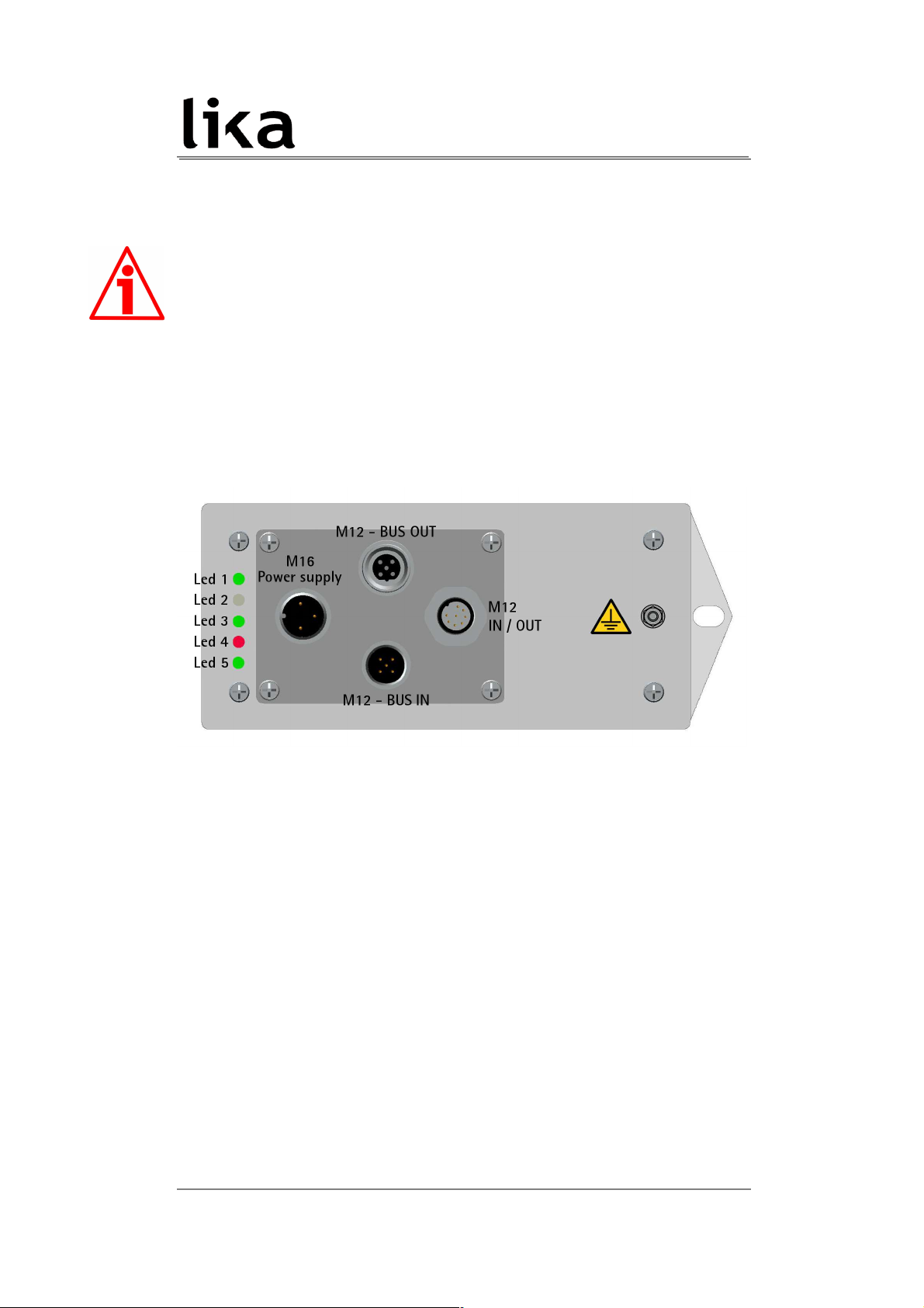
Figure 3: Electrical connections and diagnostic LEDs
4.1 Ground connection (Figure 3)
To minimize noise connect properly the frame to ground; we suggest using the
ground screw provided in the frame (see Figure above). Connect properly the
cable shield to ground on user's side. Lika's EC- pre-assembled cables are fitted
with shield connection to the connector ring nut in order to allow grounding
through the body of the device. Lika's E- connectors have a plastic gland, thus
grounding is not possible. If metal connectors are used, connect the cable shield
properly as recommended by the manufacturer. See also note in the next
paragraph. Anyway make sure that ground is not affected by noise. It is
recommended to provide the ground connection as close as possible to the
device.
MAN RD4 CB E 1.5 Electrical connections 17 of 72
Page 18
RD4 CANopen®
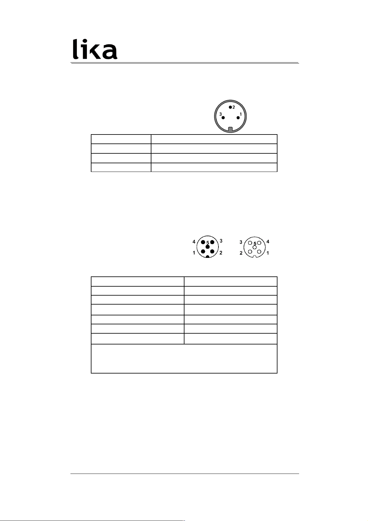
4.2 Connectors (Figure 3)
Power supply
M16 3-pin male connector
(frontal side)
Pin Description
1
+24VDC 10% motor power supply
2
+24VDC 10% controller power supply
3 motor and controller 0 VDC supply voltage
Interface
M12 5-pin connectors
A coding
(frontal side) male
(BUS IN)
female
(BUS OUT)
Pin Description
1 n.c.
2 n.c.
3
CAN GND
1
4 CAN High
5 CAN Low
Case
Shielding
2
1
CAN GND is the 0 VDC reference of CAN signals, it is not connected to 0
VDC supply voltage.
2
Lika's EC- pre-assembled cables only.
n.c. = not connected
We recommend CANopen certified cables to be used.
MAN RD4 CB E 1.5 Electrical connections 18 of 72
Page 19
RD4 CANopen®
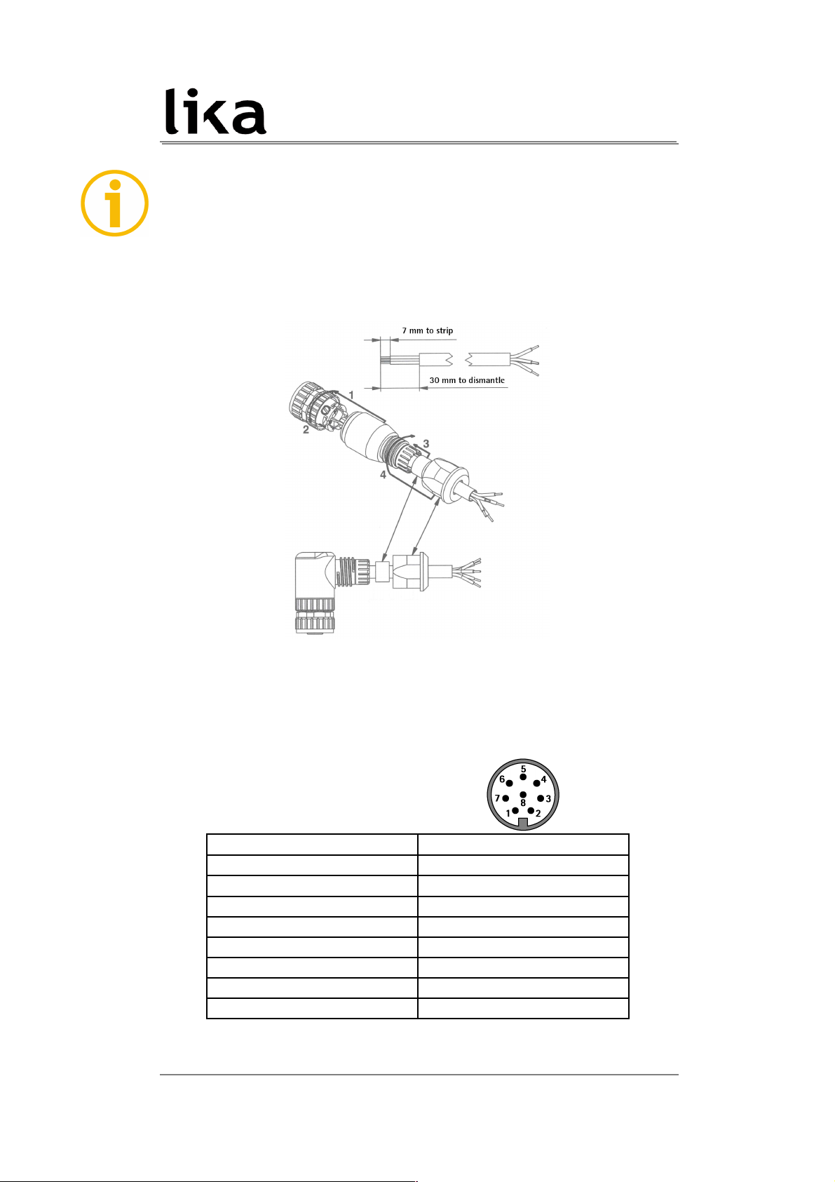
NOTE
We suggest always connecting the cable shield to ground on user's side.
Lika's EC- pre-assembled cables are fitted with shield connection to the
connector ring nut in order to allow grounding through the body of the device.
Lika's E- connectors have a plastic gland, thus grounding is not possible (see
Figure below). If metal connectors are used, connect the cable shield properly as
recommended by the manufacturer.
Inputs / outputs (optional)
M12 8-pin male connector
(frontal side)
Pin Description
1 0 VDC
2 Input 1
3 Input 2
4 Input 3
5 Output 1
6 Output 2
7 Output 3
8 n.c.
n.c.: not connected
MAN RD4 CB E 1.5 Electrical connections 19 of 72
Page 20

RD4 CANopen®
4.3 Diagnostic LEDs (Figure 3)
Five LEDs located next to the M16 power supply connector (see Figure 3) are
meant to show visually the operating or fault status of the CANopen interface
and the device as well. The meaning of each LED is explained in the following
table:
LED 1 GREEN Description
ON
Indicates the power supply of the controller is
turned on
OFF
Indicates the power supply of the controller is
turned off
LED 2
Not used
LED 3 GREEN RUN Description
ON
Device in Operational state
Single flash
Device in Stopped state
Blinking led
Device in Pre-Operational state
LED 4 RED ERR Description
ON Bus off
Double flash Node guarding error (see on page 68)
Single flash Maximum number of warning errors
Blinking led
General error or Flash memory error
OFF No error
LED 5 GREEN Description
ON
Indicates the motor is enabled (control loop
activated)
OFF
Indicates the motor is disabled (control loop
deactivated)
During initialisation, system checks the diagnostic LEDs for proper operation;
therefore they blink for a while.
MAN RD4 CB E 1.5 Electrical connections 20 of 72
Page 21
RD4 CANopen®
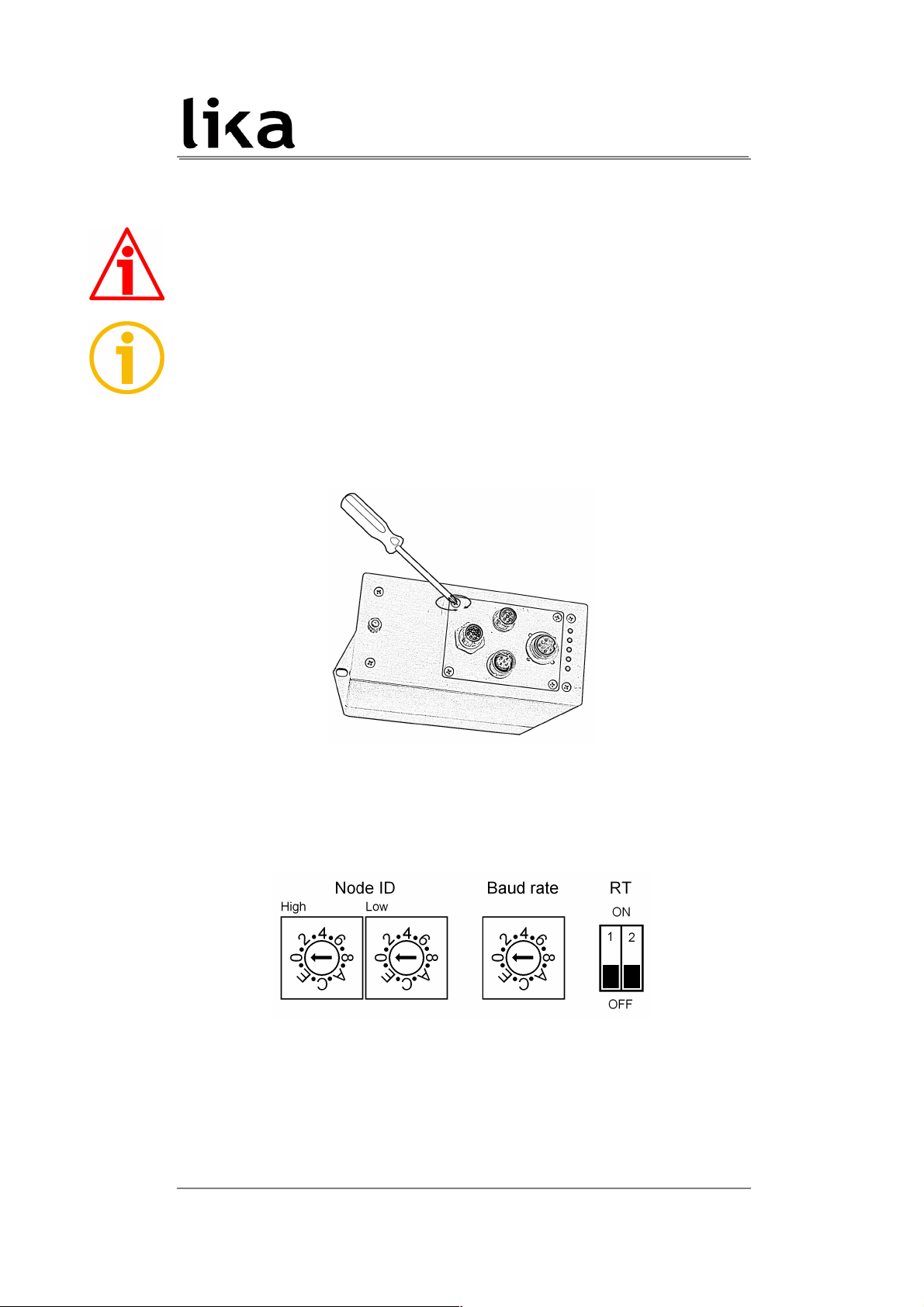
4.4 Dip-Switches (Figure 4)
WARNING
Power supply must be turned off before performing this operation!
NOTE
When performing this operation be careful not to damage the connection wires.
To access DIP-Switches loosen the four screws and remove the connectors metal
cover. Handle the cover with care not to stretch or pull out the connection
wires. Be careful to replace the metal cover at the end of the operation.
The DIP-switches are just beneath.
Figure 4: Dip-Switches
MAN RD4 CB E 1.5 Electrical connections 21 of 72
Page 22
RD4 CANopen®
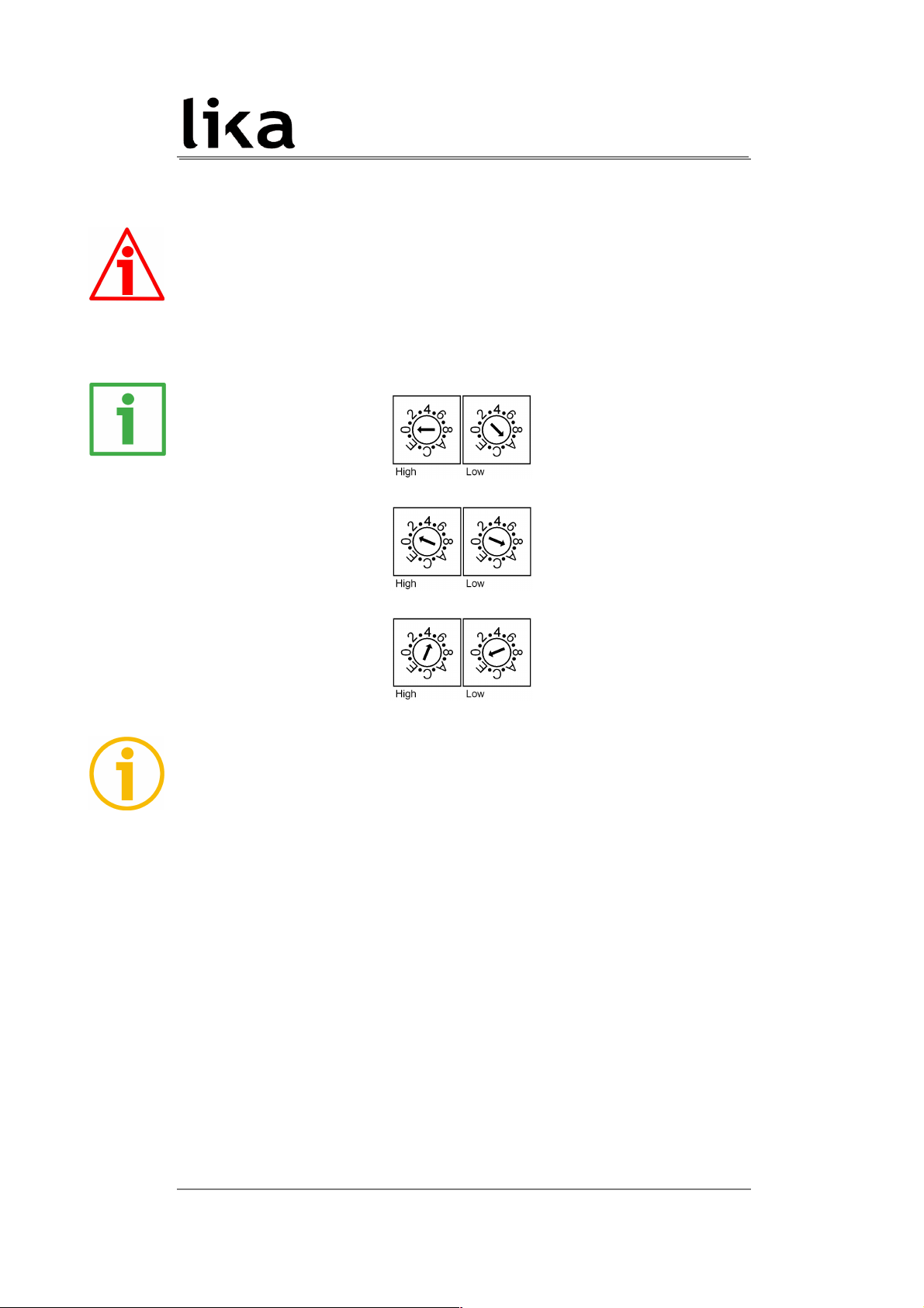
4.4.1 Setting the node address: Node ID (Figure 4)
WARNING
Power supply must be turned off before performing this operation!
Set the node address expressed in hexadecimal notation.
The range of node addresses is between 1 and 127 (127 = 7F hex).
Example
Address 10 = 0A hex:
Address 25 = 19 hex:
Address 95 = 5F hex:
NOTE
The default address is 1.
If you set the address to 0, device will be set to 1 automatically (address 0 is
reserved for Master).
If you set an address higher than 127, device will be set to 127 automatically.
MAN RD4 CB E 1.5 Electrical connections 22 of 72
Page 23

RD4 CANopen®
4.4.2 Setting the data transmission rate: Baud rate (Figure 4)
WARNING
Power supply must be turned off before performing this operation!
Set the hexadecimal value of the transmission rate according to the following
table.
Available baud rate values:
Data byte Baud rate
00h 20 Kbit/s
01h 50 Kbit/s
02h 100 Kbit/s
03h 125 Kbit/s
04h 250 Kbit/s
05h (default) 500 Kbit/s
06h 800 Kbit/s
07h 1000 Kbit/s
4.4.3 RT bus termination (Figure 4)
A bus termination resistor is provided and has to be activated as line
termination in the last device of the transmission line.
Use RT Switch to activate or deactivate the bus termination.
RT Description
1 = 2 = ON
Activated: when the device is at the end of
the transmission line
1 = 2 = OFF
Deactivated: when the device is not at the end
of the transmission line
MAN RD4 CB E 1.5 Electrical connections 23 of 72
Page 24

RD4 CANopen®
5 Quick reference
Following instructions are given to allow the operator to set up the device for
standard operation in a quick and safe manner.
• Mechanically install the device;
• execute electrical connections;
• set data transmission rate (baud rate; see on page 23);
• set the node address (node ID; see on page 22);
• switch +24VDC power supply on (in both motor and controller);
• set a proper value in 3120-00 Distance per revolution (object 3120h;
see on page 59);
• set a proper value in 3114-00 Jog speed (object 3114h; see on page 58);
• set a proper value in 3115-00 Work speed (object 3115h; see on page
58);
• set a proper value in 3300-00 Preset (object 3300h; see on page 60);
• set proper values in 310F Delta space (objects Positive delta 310Fh sub 1
and Negative delta 310Fh sub 2; see on page 57);
• save new setting values (object 1010-01 Save Parameters 1010h sub 1;
see on page 48).
NOTE
Parameters 3120-00 Distance per revolution, 3114-00 Jog speed, 3115-00
Work speed, 3300-00 Preset and 310F Delta space are closely related, hence
you have to be very attentive when you need to change the value in one of
them. For any further information please refer to page 28.
MAN RD4 CB E 1.5 Quick reference 24 of 72
Page 25

RD4 CANopen®
6 Functions
6.1 Working principle
The following scheme is intended to show schematically the working principle
of system control logic.
MAN RD4 CB E 1.5 Functions 25 of 72
Trajectory
generator
PI
position
I2t
control
Temperature
control
PWM
generator
Power
electronics
Absolute
encoder
Motor +
Reductio
n gear
-
+ +
-
Current PI
Current
transducer
Torque
limiter
Page 26

RD4 CANopen®
6.2 Movements: jog and positioning
Two kinds of movement are available in the ROTADRIVE positioning unit, they
are:
Jog: speed control;
Positioning: position and speed control.
Jog: speed control
This kind of control is intended to generate a speed trajectory which is able to
make the maximum rotation speed of the ROTADRIVE unit shaft to be equal to
the value set in 3114-00 Jog speed.
Positioning: position and speed control
This kind of control is a point-to-point movement and the maximum reachable
speed is equal to the value set in 3115-00 Work speed; set speed can be
reached only if space is long enough.
MAN RD4 CB E 1.5 Functions 26 of 72
jog=1 jog=0
Jog
speed
speed
time
Work speed
speed
time
start=1
position
time
target
Target + tolerance
Target - tolerance
“Axis in position” delay
“Axis in position”=1
Page 27

RD4 CANopen®
6.3 Digital inputs and outputs
RD4 unit is fitted with three digital inputs and three digital outputs.
Inputs are read by the Slave device and transmitted to the Master through
Status word (bits 13-15; see on page 42) when the device is running in
Operational state.
“High” logic value is read when voltage is equal to +24VDC 10%.
Slave outputs are operated by the Master through Control Word (bits 13-15;
see on page 38) when the device is running in Operational state.
Outputs are “open collector” type having Imax = 150mA.
Example of connection scheme:
MAN RD4 CB E 1.5 Functions 27 of 72
Page 28

RD4 CANopen®
6.4 Objects 3120-00 Distance per revolution, 3114-00 Jog speed, 3115-
00 Work speed, 3300-00 Preset and 310F Delta space
Objects 3120-00 Distance per revolution, 3114-00 Jog speed, 3115-00
Work speed, 3300-00 Preset and 310F Delta space are closely related, hence
you have to be very attentive every time you need to change the value in any of
them.
Should that be necessary, you have to operate in compliance with the following
procedure:
set a proper value in 3120-00 Distance per revolution (object 3120h, see
on page 59);
set a proper value in 3114-00 Jog speed (object 3114h; see on page 58);
set a proper value in 3115-00 Work speed (object 3115h; see on page 58);
set a proper value in 3300-00 Preset (object 3300h, see on page 60);
check the value in 310F Delta space sub 1 Positive delta is set properly
(object 310Fh sub 1, see on page 57);
check the value in 310F Delta space sub 2 Negative delta is set properly
(object 310Fh sub 2, see on page 57);
save new values (object 1010-01 Save Parameters 1010h sub 1, see on
page 48).
WARNING
Each time you change the value in 3120-00 Distance per revolution you
must then set new values also in 3114-00 Jog speed and 3115-00 Work
speed as speed values are expressed in pulses per second (PPS). To calculate the
speed values you have always to adhere to the following ratio:
where:
• Distance per revolution: this is the new value you want to set in 3120-
00 Distance per revolution, expressed in pulses
• Min. speed: minimum speed 1 [PPS] for all RD4 units
• Max. speed: maximum speed 1600 [PPS] for RD4-...-T32-... model
1066 [PPS] for RD4-...-T48-... model
• 1024: this is the maximum value you can set in 3120-00 Distance per
revolution (expressed in pulses).
MAN RD4 CB E 1.5 Functions 28 of 72
Min. speed ∗ Distance per revolution
1024
Speed
Max. speed ∗ Distance per revolution
1024
Page 29

RD4 CANopen®
Each time you change the value in 3120-00 Distance per revolution you
must then update the value in 3300-00 Preset in order to define the zero of
the axis as the system reference has now changed.
After having changed the parameter in 3300-00 Preset it is not necessary to
set new values for travel limits as the Preset function then calculates them
automatically and initializes again the positive and negative limits according to
the values set in 310F Delta space.
The number of revolutions managed by the system is 511 in negative direction
and 511 in positive direction assuming 3300-00 Preset as reference.
Value set in parameter 310F Delta space plus value set in parameter 3300-00
Preset is the maximum forward travel (positive travel) starting from the preset
(value is expressed in pulses).
Value set in parameter 310F Delta space subtracted from value set in
parameter 3300-00 Preset is the maximum backward travel (negative travel)
starting from the preset (value is expressed in pulses).
WARNING
Please note that the parameters listed hereafter are closely related to the 3120-
00 Distance per revolution parameter; hence when you change the value in
3120-00 Distance per revolution also the value expressed by each one is
necessarily redefined. They are: 3108-00 Acceleration, 3109-00
Deceleration, 310C-00 Max following error, 310D-00 Position window,
310F Delta space, 3116-00 Max speed, 3343-00 Positive absolute limit
switch, 3344-00 Negative absolute limit switch, 3103-00 Current
position value, 3105-00 Current velocity value, 3106-00 Target position
and 3107-00 Target speed. See for instance the relationship between 3120-
00 Distance per revolution and the speed values, explained in the previous
page.
MAN RD4 CB E 1.5 Functions 29 of 72
Page 30

RD4 CANopen®
Example 1
Default values:
3120-00 Distance per revolution = 1024 steps per revolution
Max. 3115-00 Work speed:
= 1600 pulses per second for RD4-...T32-... model (1600*1024/1024 = 1600)
= 1066 pulses per second for RD4-...T48-... model (1066*1024/1024 = 1066)
3300-00 Preset = 0
310F Delta space sub 1 Positive delta and 310F Delta space sub 2 Negative
delta max. values = 523263 = (1024 steps per revolution x 511 revolutions) - 1
when 3300-00 Preset value = 0
Max. SW limit switch + = 0 + 523263 = + 523263 pulses (forward travel)
Max. SW limit switch - = 0 - 523263 = - 523263 pulses (backward travel)
Therefore, when 3300-00 Preset = 0, the working stroke of the axis will span
the maximum positive and negative limits range, that is SW limit switch + =
523263 and SW limit switch - = - 523263.
MAN RD4 CB E 1.5 Functions 30 of 72
Page 31

RD4 CANopen®
Example 2
ROTADRIVE RD4-...T32-... positioning unit is joined to a worm screw having a 1
mm pitch and you need to have a hundredth of a millimetre resolution.
3120-00 Distance per revolution = 100 steps per revolution
Max. 3115-00 Work speed = 156 pulses per second (1600*100/1024 = 156,
rounded off to the nearest integer)
3300-00 Preset = -500 (ex. thickness of the tool)
310F Delta space sub 1 Positive delta and 310F Delta space sub 2 Negative
delta max. values = 100 steps per revolution x 511 revolutions = 51100 pulses
Max. SW limit switch + = (-500) + 51100 = + 50600 pulses (forward travel)
Max. SW limit switch - = (-500) - 51100 = - 51600 pulses (backward travel)
Therefore, when 3300-00 Preset = - 500, the working stroke of the axis will
span the maximum positive and negative limits range, that is SW limit switch
+ = + 50600 and SW limit switch - = - 51600.
MAN RD4 CB E 1.5 Functions 31 of 72
Page 32

RD4 CANopen®
7 CANopen® interface
Lika ROTADRIVE positioning units are Slave devices and are designed in
compliance with the “Application Layer and Communication Profile DS301”.
For any further information or omitted specifications please refer to “CiA Draft
Standard 301” document available at www.can-cia.org.
7.1 EDS files
CANopen® devices are supplied with their own EDS file
LIKA_RD4_Tx_I2_Vx.EDS (see enclosed documentation or click www.lika.biz >
ROTARY ACTUATORS > ROTARY ACTUATORS (DRIVECOD) > RD4). EDS file
has to be installed on CANopen® Master device.
Install LIKA_RD4_T32_I2_Vx.EDS file for devices fitted with T32 reduction
gear.
Install LIKA_RD4_T48_I2_Vx.EDS file for devices fitted with T48 reduction
gear.
EDS files are available in both English version (_en) and Italian version (_it).
MAN RD4 CB E 1.5 CANopen® interface 32 of 72
Page 33

RD4 CANopen®
7.2 NMT states
CANopen® devices are designed to operate using different states. Transition
from one state to another is achieved by sending specific NMT messages (see
Figure below).
(1) Power turned on
(2)
Initialization carried out, boot-up message is sent
automatically
(3)
NMT message: Start remote node
(4)
NMT message: Enter pre-operational
(5)
NMT message: Stop remote node
(6)
NMT message: Reset node or Reset communication
7.2.1 Initialization
This is the first state the CANopen® device enters after power is turned on or
after performing a hardware reset by means of a Reset node command. During
initialization, device reads and loads the parameters saved on EPROM. As soon
as the basic CANopen® device initialization is carried out, device sends a bootup message and then switches automatically to Pre-operational state.
MAN RD4 CB E 1.5 CANopen® interface 33 of 72
Initialization
Pre-operational
Operational
Stopped
Boot-up message
(1)
(2)
(3)
(4)
(4)(5)
(5) (3)
(6)
(6)
(6)
Page 34

RD4 CANopen®
7.2.2 Pre-operational state
In this state communication between Master and Slave is possible using SDO
messages. They allow working parameters to be set. Slave cannot send PDO
messages.
To switch the Slave device to Operational state the Master must send a Start
remote node command using a NMT message.
7.2.3 Operational state
In this state the Slave device is active and all communication objects are
available. The Slave device can use the parameters available in the “Object
dictionary” and is allowed to send process data using PDO messages. “Object
dictionary” can be accessed using SDO messages. To switch the Slave device to
Pre-operational state the Master must send an Enter pre-operational
command using a NMT message.
WARNING
For safety reasons, in Operational state the Master must check the Slave device
continuously and in a proper way. For a description of the correct procedure see
section “7.6 PDO messages” on page 37.
7.2.4 Stopped state
In this state the Slave device is forced to interrupt communication with the
Master altogether (except node guarding, if active).
Communication using PDO and SDO messages is not allowed.
To switch the Slave device to Pre-Operational or Operational state the Master
must send the specific commands Enter pre-operational or Start remote
node using a NMT message.
MAN RD4 CB E 1.5 CANopen® interface 34 of 72
Page 35

RD4 CANopen®
7.3 Communication messages
Four different kinds of communication messages are used in a CANopen®
network:
Network management NMT service: through node control services, the NMT
Master controls the NMT state of the NMT Slaves; see “7.4 NMT messages”
section on page 36.
Process Data Object PDO service: the real-time data transfer is performed
by means of “Process Data Objects (PDO)”. The PDOs correspond to entries in
the object dictionary and provide the interface to the application objects;
see “7.6 PDO messages” section on page 37.
Service Data Object SDO service: SDOs used to provide direct access to
entries of a CANopen® device “Object dictionary” (page 46); they allow to
read and set parameters; see “7.7 SDO messages” section on page 45.
Special Function Object services:
- SYNC: synchronization object provides the basic network synchronization
mechanism and is used by the Master to enable the Slave devices to
transmit process data (position and velocity; see on page 47);
- Emergency EMCY: emergency objects are triggered by the occurrence of a
CANopen® device internal error situation, see on page 67;
- Node guarding protocol: it is used to detect remote errors in the network,
see on page 68.
Relation between device states and communication objects:
Initialization Pre-operat. Operational Stopped
NMT X X X
PDO X
SDO X X
SYNC X
EMCY X X
Boot-up X
Nodeguard X X X
MAN RD4 CB E 1.5 CANopen® interface 35 of 72
Page 36

RD4 CANopen®
7.3.1 Generic pre-defined connection set
Broadcast objects of the generic pre-defined connection set
Type of COB (Object)
Function code
(binary)
COB-ID (hex)
NMT 0000 000
SYNC 0001 080
Peer-to-peer objects of the generic pre-defined connection set
EMERGENCY 0001 081 - 0FF
PDO 1 (tx) 0011 181 - 1FF
PDO 1 (rx) 0100 200 - 27F
SDO (tx) 1011 581 - 5FF
SDO (rx) 1100 601 - 67F
Nodeguard 1110 701 - 77F
Boot-up 1110 701 - 77F
The type of COB (tx means COB-ID sent; rx means COB-ID received) is viewed
from the Slave device.
7.4 NMT messages
Structure of NMT messages:
COB-ID (11 bit) 2 CAN Data Bytes
Func.code Node ID Command Slave ID
0000 0 NMT function Slave ID
If Slave ID = 00h, the NMT message is issued to all network nodes.
Command NMT service Node state
01 hex
Start remote node Operational
02 hex
Stop remote node Stopped
80 hex
Enter pre-operational Pre-operational
81 hex
Reset node Pre-operational
82 hex
Reset communication Pre-operational
MAN RD4 CB E 1.5 CANopen® interface 36 of 72
Page 37

RD4 CANopen®
7.5 Boot-up messages
Structure of Boot-up messages:
COB-ID(hex) 1 CAN Data Byte
700+Node ID 00
7.6 PDO messages
WARNING
For safety reasons, when the ROTADRIVE unit is on a continuous data exchange
between the Master and the Slave has to be planned in order to be sure that the
communication is always active; this is intended to prevent danger situations
from arising in case of failures in the communication network.
For monitoring the communication state in the network, among the possible
methods the Node guarding protocol can be implemented (complying with
DS301 specifications, see on page 68).
ROTADRIVE positioning unit sends PDO messages to the Master according to the
set cyclic or synchronous work mode (see object 1800 Transmit PDO
Communication Parameter 1).
PDO messages have always a 8 CAN Data Bytes format. Please note that the
structure of sent messages and received messages is different anyway.
Structure of RECEIVE PDO1 messages received by the Slave device (sent by the
Master):
IDENTIFIER 8 CAN data byte
COB-ID (hex) 0 1 2 3 4 5 6 7
F.C. Node-ID
Control Word Target position
200+ Node ID Low … … High Low … … High
MAN RD4 CB E 1.5 CANopen® interface 37 of 72
Page 38

RD4 CANopen®
Structure of TRANSMIT PDO1 messages sent by the Slave device (received by
the Master):
IDENTIFIER 8 CAN data byte
COB-ID (hex) 0 1 2 3 4 5 6 7
F.C. Node-ID
Status word
Current
velocity
Current position
180+ Node ID Low High Low High Low … … High
Structure of bytes:
bit 7 6 5 4 3 2 1 0
M.S.bit L.S.bit
7.6.1 “RECEIVE PDO1” message sent by the Master to the Slave
Control Word
Index 0x3100-00. 32 bits. It contains the commands to be sent in real time to
the Slave in order to manage it. See also 3100-00 Control word on page 63.
Byte 0
Jog +
bit 0 If bit 4 Incremental jog = 0, as long as Jog + = 1, the Slave
moves toward positive direction; otherwise if bit 4
Incremental jog = 1, the activation of this bit causes at
rising edge the execution of a single step toward positive
direction having the length, expressed in pulses, set next to
the 3117-00 Jog step length item; then the slave stops
and waits for another issue. Velocity, acceleration and
deceleration are set in objects 3114-00 Jog speed, 3108-
00 Acceleration and 3109-00 Deceleration respectively.
For a detailed description of jog control see on page 26.
Jog -
bit 1 If bit 4 Incremental jog = 0, as long as Jog - = 1, the Slave
moves toward negative direction; otherwise if bit 4
Incremental jog = 1, the activation of this bit causes at
rising edge the execution of a single step toward negative
direction having the length, expressed in pulses, set next to
the 3117-00 Jog step length item; then the slave stops
and waits for another issue. Velocity, acceleration and
MAN RD4 CB E 1.5 CANopen® interface 38 of 72
Page 39

RD4 CANopen®
deceleration are set in objects 3114-00 Jog speed, 3108-
00 Acceleration and 3109-00 Deceleration respectively.
For a detailed description of jog control see on page 26.
Stop
bit 2 If set to “=1” the Slave is allowed to execute the movements
as commanded. If, while the unit is running, this bit
switches to “=0” then the Slave must stop executing the
deceleration procedure set in 3109-00 Deceleration. For
an immediate halt in the movement, use bit 7 Emergency.
Alarm reset
bit 3 Setting this bit to “1” causes the normal work status of the
device to be restored. This command is used to reset an
alarm condition of the Slave but only if the faulty condition
has ceased. Using SDO messages you can read further
information about the alarm in the index 1003 Pre-
defined Error Field.
Please note that should the alarm be caused by wrong
object values (Machine data not valid) normal work status
can be restored only after having set proper values. Flash
memory error alarm cannot be reset.
Incremental jog
bit 4 If set to “=0”, the activation of bits Jog + and Jog - causes
the slave to move as long as Jog + / Jog - = 1. Setting this
bit to 1 the incremental jog function is enabled, that is: the
activation of bits Jog + and Jog - causes at rising edge the
execution of a single step toward positive or negative
direction having the length, expressed in pulses, set next to
the 3117-00 Jog step length item; then the slave stops
and waits for another issue.
bit 5 Not used.
Start
bit 6 If set to “=1” device moves in order to reach the set target
position. For a complete description of the position control
see on page 25. For any information on target position see
Target position on page 41.
Emergency
bit 7 This bit has to be normally high (“=1”), otherwise it will
cause the device to stop immediately. For a normal halt (not
immediate) which respects the set deceleration see above
bit 2 Stop.
MAN RD4 CB E 1.5 CANopen® interface 39 of 72
Page 40

RD4 CANopen®
Byte 1
bit 8 … 11 Not used.
Axis torque
bit 12 When the axis has reached the commanded position, it
keeps the torque.
If set to “=0”, when the axis is in position, PWM is
deactivated.
If set to ”=1”, when the axis is in position, PWM is kept
active.
OUT 1
bit 13 This is intended to activate / deactivate the operation of the
digital output 1. The meaning of the available outputs is
described in section “Programming parameters“ on page 46.
OUT 1 = 0 output 1 low (not active)
OUT 1 = 1 output 1 high (active)
OUT 2
bit 14 This is intended to activate / deactivate the operation of the
digital output 2. The meaning of the available outputs is
described in section “Programming parameters“ on page 46.
OUT 2 = 0 output 2 low (not active)
OUT 2 = 1 output 2 high (active)
OUT 3
bit 15 This is intended to activate / deactivate the operation of the
digital output 3. The meaning of the available outputs is
described in section “Programming parameters“ on page 46.
OUT 3 = 0 output 3 low (not active)
OUT 3 = 1 output 3 high (active)
Bytes 2 and 3 Not used.
MAN RD4 CB E 1.5 CANopen® interface 40 of 72
Page 41

RD4 CANopen®
Bytes 4 … 7
Target position
Position to be reached, otherwise referred to as commanded position. When the
Start command is sent while Stop and Emergency bits are “=1” and the alarm
condition is off, device moves in order to reach the target position.
Position override function
It is possible to change the target position value even while the device is still
reaching it; to do this, send a Start command and the new target value in
Target position.
NOTE
Jog +, Jog - and Start functions cannot be enabled simultaneously. For
instance: if a Jog + command is sent to the Slave while it is moving to target
position, jog command will be ignored; if Jog + and Jog - commands are sent
simultaneously, device does not move or, if already moving, it stops its
movement.
MAN RD4 CB E 1.5 CANopen® interface 41 of 72
Page 42

RD4 CANopen®
7.6.2 “TRANSMIT PDO1” message sent by the Slave to the Master
Status word
Index 0x3101-00. 16 bits. In these bytes the status of the PI controller in
Operational work mode is shown. See also 3101-00 Status word on page 63.
Byte 0
Axis in position
bit 0 If value is “=1” device has reached the set position for
the time set in 310E-00 Position window time. It is
kept active until the position error is lower than
310D-00 Position window.
bit 1 Not used.
Axis enabled
bit 2 It shows the enabling status of the motor. This bit is
"=1" when the motor is enabled, that is: PWM is
active and the axis is under closed-loop control (while
reaching a target position or using a jog, for
instance). It is "=0" when the motor is disabled, that is
when the controller is off after a positioning or jog
movement or because of an alarm condition.
SW limit switch +
bit 3 If value is “=1” device has reached the maximum
positive limit (positive limit switch). See object 310F
Delta space sub 1 Positive delta.
SW limit switch -
bit 4 If value is “=1” device has reached the maximum
negative limit (negative limit switch). See object 310F
Delta space sub 2 Negative delta.
Alarm
bit 5 If value is “=1” an alarm has occurred, see details at
indexes 1003 Pre-defined Error Field and 3200-00
Alarms.
Axis running
bit 6 If value is ”=0” device is not moving.
If value is “=1” device is moving.
Executing a command
bit 7 If value is “=0” controller is not executing any
command.
If value is “=1” controller is executing a command.
MAN RD4 CB E 1.5 CANopen® interface 42 of 72
Page 43

RD4 CANopen®
Byte 1
Target position reached
bit 8 If value is “=1” device has reached the target position
(see Target position). Bit is kept active until new
Target position value or Alarm reset commands are
sent.
bits 9 ... 11 Not used.
DAC Saturation
bit 12 The current supplied by power electronic for
controlling the motor has reached the maximum
value and cannot be increased further.
IN 1
bit 13 This is meant to show the status of the digital input 1.
The meaning of the available inputs is described in
section “Programming parameters“ on page 46.
IN 1 = 0 input 1 low (not active)
IN 1 = 1 input 1 high (active)
IN 2
bit 14 This is meant to show the status of the digital input 2.
The meaning of the available inputs is described in
section “Programming parameters“ on page 46.
IN 2 = 0 input 2 low (not active)
IN 2 = 1 input 2 high (active)
IN 3
bit 15 This is meant to show the status of the digital input 3.
The meaning of the available inputs is described in
section “Programming parameters“ on page 46.
IN 3 = 0 input 3 low (not active)
IN 3 = 1 input 3 high (active)
Bytes 2 and 3
Current velocity
Speed of the device expressed in pulses per second [PPS], updated at every
second.
Bytes 4 … 7
Current position
Absolute position of the device when the PDO message is sent.
MAN RD4 CB E 1.5 CANopen® interface 43 of 72
Page 44

RD4 CANopen®
Example 1
Positioning RD4
Start (bit 6 - Control Word)
Executing a command (bit 7 - Status word)
Axis running (bit 6 - Status word)
Axis in position (bit 0 - Status word)
Target position reached (bit 8 - Status word)
Axis enabled (bit 2 - Status word: PWM is
active)
Theoretical velocity
Example 2
Jog + RD4
Jog + (bit 0 - Control Word)
Executing a command (bit 7 - Status word)
Axis running (bit 6 - Status word)
Axis enabled (bit 2 - Status word: PWM is
active)
Theoretical velocity
MAN RD4 CB E 1.5 CANopen® interface 44 of 72
Page 45

RD4 CANopen®
7.7 SDO messages
SDO messages are used to set new values to and read values from the device.
These parameters are described in the “Object dictionary” (see on page 46).
4 bytes at the most are used for CAN data, other 4 bytes are used for Command,
Index and Sub-index fields. SDO messages always need confirmation from the
Slave. It follows that when the Master sends a SDO message to the Slave, the
Slave always sends a reply (and a warning, should an error occur).
SDO structure:
IDENTIFIER from 4 to 8 CAN data bytes
COB-ID(hex) 0 1 2 3 4 5 6 7
F.C. Node-ID Com Index Sub Data
1 byte LSB MSB 1 byte LSB … … MSB
Com command
Index parameter index
Sub parameter sub-index
Data parameter value (set or read value)
7.7.1 Command
Command byte contains the type of COB telegram transmitted to the CAN
network.
Three types of telegram are available:
Set: used to send configuration parameters to the Slave;
Req: used by the Master to read data from the Slave;
Warnings: used by the Slave to send error messages to the Master (e.g.
“Index does not exist”, “Process data value not valid”, etc.).
Command COB COB type Data length
22h Set M S request not specif.
23h Set M S request 4 byte
2Bh Set M S request 2 byte
2Fh Set M S request 1 byte
60h Set S M confirmation 0 byte
40h Req M S request 0 byte
42h Req S M reply non specified
43h Req S M reply 4 byte
4Bh Req S M reply 2 byte
4Fh Req S M reply 1 byte
41h Req S M reply segmented SDO
80h Warning S M reply 4 byte
MAN RD4 CB E 1.5 CANopen® interface 45 of 72
Page 46

RD4 CANopen®
8 Programming parameters
8.1 Objects dictionary
In the following pages the objects implemented are listed and described as
follows:
Index-subindex Object name
[data types, attribute]
Index and subindex are expressed in hexadecimal notation.
Attribute:
ro = read only access
rw = read and write access
const = ro + constant value
Unsigned16 data type:
Data byte
byte 4 byte 5
LSByte MSByte
Unsigned32 data type:
Data byte
byte 4 byte 5 byte 6 byte 7
LSByte … … MSByte
8.1.1 Standard objects (DS 301)
1000-00 Device type
[Unsigned32, const]
Default = 0000012Dh
1001-00 Error register
[Unsigned8, ro]
Should an error occur, bit 0 of this object will be set to “1”.
Default = 00h
MAN RD4 CB E 1.5 Programming parameters 46 of 72
Page 47

RD4 CANopen®
1003 Pre-defined Error Field
This object contains the list of the five previous errors which generated an EMCY
emergency message.
00 Number of current errors [Unsigned8, rw]
Enter 00h to delete the errors list.
01 Last error occurred [Unsigned32, ro]
02…05 Previous errors occurred [Unsigned32, ro]
1005-00 COB-ID SYNC messages
[Unsigned32, rw]
Default = 0000 0080h
1008-00 Device name
[String, const]
It shows the name of the device.
Default = “RD4”
1009-00 Hardware Version
[String, const]
It shows the hardware version of the device.
100A-00 Software Version
[String, const]
It shows the software version of the device.
100C-00 Guard Time
[Unsigned16, rw]
It contains the “node guard time” value expressed in msec (milliseconds). The
Master polls each Slave at regular time intervals issuing RTR messages. This
time-interval is called the “node guard time” and may be different for each
Slave. For further details see section “8.4 Node guarding protocol” on page 68.
Default = 0
MAN RD4 CB E 1.5 Programming parameters 47 of 72
Page 48

RD4 CANopen®
100D-00 Life Time Factor
[Unsigned8, rw]
Default = 0
100C-00 Guard Time and 100D-00 Life Time Factor objects are used in
“Node guarding protocol” controlled by Master. For further details see section
“8.4 Node guarding protocol” on page 68.
1010-01 Save Parameters
[Unsigned32, rw]
Use this object to save all parameters on non-volatile memory.
Write save (ASCII code in hexadecimal form) in the data bytes:
Master Slave
COB-ID Cmd Index Sub Data bytes
600+ID 23 10 10 01 73 61 76 65
Slave Master (confirmation)
COB-ID Cmd Index Sub Data bytes
580+ID 60 10 10 01 00 00 00 00
1011-01 Restore Default Parameters
[Unsigned32, rw]
This object allows you to restore all parameters to default values (they are set at
the factory by Lika Electronic engineers to allow the operator to run the device
for standard operation in a safe mode).
Write load (ASCII code in hexadecimal form) in the data bytes and then issue a
Reset node command:
Master Slave
COB-ID Cmd Index Sub Data bytes
600+ID 23 11 10 01 6C 6F 61 64
Slave Master (confirmation)
COB-ID Cmd Index Sub Data bytes
580+ID 60 11 10 01 00 00 00 00
Master Slave (reset node)
COB-ID Cmd Slave ID
000 81 ID
MAN RD4 CB E 1.5 Programming parameters 48 of 72
Page 49

RD4 CANopen®
Slave Master (Boot-up)
COB-ID Cmd
700+ID 00
NOTE
Save default values using 1010-01 Save Parameters function.
1014-00 COB-ID EMCY
[Unsigned32, rw]
This object defines the COB-ID used to send emergency messages (EMCY).
When the power is turned on, this object always contains the default value.
For a complete list of the emergency messages refer to section “8.3 Emergency
messages” on page 67.
Default = 80h+Node ID
1015-00 Inhibit Time Emergency
[Unsigned16, rw]
Inhibit time of emergency messages (EMCY), i.e. minimum interval between
subsequent emergency messages expressed in multiples of 100 µs.
Default = 0
1018 Identity Object
01 Vendor Id [Unsigned32, ro]
02 Product code [Unsigned32, ro]
03 Revision number [Unsigned32, ro]
04 Serial number [Unsigned32, ro]
MAN RD4 CB E 1.5 Programming parameters 49 of 72
Page 50

RD4 CANopen®
1400 Receive PDO Communication Parameter 1
This object contains the communication parameters for the PDOs the device is
able to receive (Receive PDOs).
01 COB-ID of PDO1 [Unsigned32, rw]
Bit number Value Meaning
31 (MSB)
0 PDO exists / is valid
1 PDO does not exist / is not valid
30
0
RTR allowed on this PDO (not implemented)
1 no RTR allowed on this PDO
29
0 11-bit ID (CAN 2.0A)
1 29-bit ID (CAN 2.0B)
28 … 11
0 if bit 29 = 0
X if bit 29 = 1: bits 28-11 of 29-bit-COB-ID
10 … 0 (LSB)
X bits 10-0 of COB-ID
Default = 4000 0200h+Node ID (no RTR, COB-ID)
WARNING
It is mandatory to set the bit 30 of COB-ID to 1 (value 0 is not allowed).
This means that “No RTR is allowed on the PDO”.
At power on, this object always contains the default value.
02 Transmission Type [Unsigned8, rw]
Transmission type PDO transmission
00h (0)
Acyclic, synchronous
not implemented
01h … F0h (1 … 240)
Cyclic, synchronous
implemented
F1h … FBh (241 … 251) not implemented - reserved
FCh (252)
Synchronous, RTR only
not implemented
FDh (253)
Asynchronous, RTR only
not implemented
FEh (254)
Asynchronous,
manufacturer specific
implemented
FFh (255)
Asynchronous, device
profile specific
not implemented
Default = FEh (event-driven, asynchronous, manufacturer specific)
MAN RD4 CB E 1.5 Programming parameters 50 of 72
Page 51

RD4 CANopen®
WARNING
Following an attempt to set the Transmission Type to 0, the PDO
message is not sent; following an attempt to change the Transmission
Type to any other value that is not supported by the device, an abort
message (abort code = 0609 0030h: Value range of parameter
exceeded) is generated.
NOTE
- Before altering the value of COB-ID it is compulsory to deactivate the receipt
of PDO1, then enter the new COB-ID value, finally activate again the receipt of
PDO1.
- PDO1 receipt can be activated (deactivated) by setting to “0” (“1”) the most
significant bit of the object 1400 Receive PDO Communication Parameter
1 sub 1 COB-ID.
1600 Receive PDO Mapping Parameter 1
This object indicates the kind of parameter contained in the Receive PDO
message.
01 3100-00 Control word [Unsigned32, ro] Default = 3100 0020h.
02 3106-00 Target position [Unsigned32, ro] Default = 3106 0020h.
1800 Transmit PDO Communication Parameter 1
These objects contain the communication parameters of Transmit PDO.
01 COB-ID of PDO1 [Unsigned32, rw]
Bit number Value Meaning
31 (MSB)
0 PDO exists / is valid
1 PDO does not exist / is not valid
30
0
RTR allowed on this PDO (not implemented)
1 no RTR allowed on this PDO
29
0 11-bit ID (CAN 2.0A)
1 29-bit ID (CAN 2.0B)
28 … 11
0 if bit 29 = 0
X if bit 29 = 1: bits 28-11 of 29-bit-COB-ID
10 … 0 (LSB)
X bits 10-0 of COB-ID
MAN RD4 CB E 1.5 Programming parameters 51 of 72
Page 52

RD4 CANopen®
Default = 4000 0180h+Node ID (no RTR, COB-ID)
WARNING
It is mandatory to set the bit 30 of COB-ID to 1 (value 0 is not allowed).
This means that “No RTR is allowed on the PDO”.
At power on, this object always contains the default value.
02 Transmission Type [Unsigned8, rw]
Transmission type PDO transmission
00h (0)
Acyclic, synchronous
not implemented
01h … F0h (1 … 240)
Cyclic, synchronous
implemented
F1h … FBh (241 … 251) not implemented - reserved
FCh (252)
Synchronous, RTR only
not implemented
FDh (253)
Asynchronous, RTR only
not implemented
FEh (254)
Asynchronous,
manufacturer specific
implemented
FFh (255)
Asynchronous, device
profile specific
not implemented
Default = FEh (“status, position, velocity exchange” transmission or
cyclic transmission, see hereafter and object 3110-00 Cyclic Time)
WARNING
Following an attempt to set the Transmission Type to 0, the PDO
message is not sent; following an attempt to change the Transmission
Type to any other value that is not supported by the device, an abort
message (abort code = 0609 0030h: Value range of parameter
exceeded) is generated.
If the value next to the object 3110-00 Cyclic Time ≠ 0, the PDO
message is sent cyclically and the interval between two messages is the
time set next to the object 3110-00 Cyclic Time; otherwise, if the
value next to the object 3110-00 Cyclic Time = 0, the PDO message is
sent only at each status exchange (see object 3101-00 Status word)
and/or position exchange (see object 3103-00 Current position value)
and/or velocity exchange (see object 3105-00 Current velocity value);
in this case the minimum interval between two PDO transmissions is set
next to the following parameter Inhibit Time object 1800h sub 3.
MAN RD4 CB E 1.5 Programming parameters 52 of 72
Page 53

RD4 CANopen®
03 Inhibit Time [Unsigned16, rw]
Minimum interval between two PDO transmissions when “status,
position, velocity exchange” transmission is set (see the parameter
Transmission Type object 1800h sub 2 and the NOTE just below); value
is expressed in multiples of 100 µs.
Default = 0190h (40ms)
NOTE
- Before altering the value of COB-ID it is compulsory to deactivate the
transmission of PDO1, then enter the new COB-ID value, finally activate again
the transmission of PDO1.
- PDO1 transmission can be activated (deactivated) by setting to “0” (“1”) the
most significant bit of the object 1800 Transmit PDO Communication
Parameter 1 sub 1 COB-ID.
- Cyclic transmission or synchronous transmission can be modified by setting a
suitable value in the object 1800 Transmit PDO Communication Parameter
1 sub 2 Transmission Type. To have a PDO1 transmission every “n” SYNC
commands, set “n” value in the object 1800h, sub 2.
01h = synchronous transmission at every SYNC command
02h = synchronous transmission every two SYNC commands
…
FEh = “cyclic transmission” or “status, position, velocity exchange
transmission”:
if 3110-00 Cyclic Time ≠ 0 “cyclic transmission”: cycle time is set in
object 3110h;
if 3110-00 Cyclic Time = 0 “status, position, velocity exchange”
transmission: device issues a PDO message each time parameters
mapped in PDO change (see object 1A00 TPDO Mapping Parameter 1)
with a minimum interval not lower than 1800 Transmit PDO
Communication Parameter 1 sub 3 Inhibit Time.
1A00 TPDO Mapping Parameter 1
This object indicates the kind of parameter contained in the Transmit PDO
message.
01 3101-00 Status word [Unsigned32, ro] Default = 3101 0010h.
02 3105-00 Current velocity value [Unsigned32, ro] Default = 3105
0010h.
03 3103-00 Current position value [Unsigned32, ro] Default = 3103
0020h.
MAN RD4 CB E 1.5 Programming parameters 53 of 72
Page 54

RD4 CANopen®
NOTE
Save set values using 1010-01 Save Parameters function.
Should the power be turned off or Reset node or Reset communication
commands be sent all data not saved will be lost!
MAN RD4 CB E 1.5 Programming parameters 54 of 72
Page 55

RD4 CANopen®
8.1.2 Manufacturer's specific objects
Communication parameters
3000-00 Baud rate
[Unsigned8, ro]
This object is meant to show the baud rate (transmission rate) set by means of
the dedicated switch, according to the following table; for any information on
setting the baud rate see section “4.4.2 Setting the data transmission rate: Baud
rate (Figure 4)“ on page 23.
Data byte Baud rate
00h 20 Kbit/s
01h 50 Kbit/s
02h 100 Kbit/s
03h 125 Kbit/s
04h 250 Kbit/s
05h (default) 500 Kbit/s
06h 800 Kbit/s
07h 1000 Kbit/s
3001-00 Node ID
[Unsigned8, ro]
This object is meant to show the node identifier (address) of the device set by
means of the dedicated switch; for any information on setting the node-ID see
section “4.4.1 Setting the node address: Node ID (Figure 4)” on page 22. The
default address is 1.
MAN RD4 CB E 1.5 Programming parameters 55 of 72
Page 56

RD4 CANopen®
Device profile objects
3108-00 Acceleration
[Unsigned32, rw]
This object defines the acceleration value that has to be used by the device.
Parameter is expressed in pulses per second2 [PPS2].
Default = 1000
3109-00 Deceleration
[Unsigned32, rw]
This object defines the deceleration value that has to be used by the device.
Parameter is expressed in pulses per second2 [PPS2].
Default = 1000
310C-00 Max following error
[Unsigned32, rw]
This object defines the maximum allowable difference between the real position
and the theoretical position of the device. If the device detects a value higher
than the one set in this object, the alarm Following error is triggered and the
unit stops. Parameter is expressed in pulses.
Default = 1024
310D-00 Position window
[Unsigned16, rw]
This object defines the tolerance window for the 3106-00 Target position
value. When the axis is within the tolerance window limits for the time set in
the object 310E-00 Position window time, then the state is signalled through
the Axis in position status bit. Parameter is expressed in pulses.
Default = 0
310E-00 Position window time
[Unsigned16, rw]
It represents the time for which the axis has to be within the tolerance window
limits set in the object 310D-00 Position window before the state is signalled
through the Axis in position status bit. Parameter is expressed in milliseconds.
Default = 100
MAN RD4 CB E 1.5 Programming parameters 56 of 72
Page 57

RD4 CANopen®
310F Delta space
01 Positive delta [Integer32, rw]
This value is used to calculate the maximum forward (positive) limit the
device is allowed to reach starting from the preset value. When the
maximum forward limit is reached, a signalling is activated through the
SW limit switch + status bit. Parameter is expressed in encoder pulses.
SW limit switch + = 3300-00 Preset + 310F Delta space sub 1
Positive delta.
Default = 523263
02 Negative delta [Integer32, rw]
This value is used to calculate the maximum backward (negative) limit
the device is allowed to reach starting from the preset value. When the
maximum backward limit is reached, a signalling is activated through
the SW limit switch - status bit. Parameter is expressed in encoder
pulses.
SW limit switch - = 3300-00 Preset - 310F Delta space sub 2
Negative delta.
Default = 523263
WARNING
Every time 3120-00 Distance per revolution and 3300-00 Preset
parameters are changed, 310F Delta space values has to be checked carefully.
Each time you change the value in 3120-00 Distance per revolution you
must then update the value in 3300-00 Preset in order to define the zero of
the shaft as the system reference has now changed.
After having changed the parameter in 3300-00 Preset it is not necessary to
set new values for travel limits as the Preset function then calculates them
automatically and initializes again the positive and negative limits according to
the values set in 310F Delta space. For a detailed explanation see on page 28.
3111-00 Kp position loop
[Unsigned32, rw]
This object contains the proportional gain used by the PI controller for the
position loop. Value has been optimized by Lika Electronic according to the
technical characteristics of the device.
Default = 500
MAN RD4 CB E 1.5 Programming parameters 57 of 72
Page 58

RD4 CANopen®
3112-00 Ki position loop
[Unsigned32, rw]
This object contains the integral gain used by the PI controller for the position
loop. Value has been optimized by Lika Electronic according to the technical
characteristics of the device.
Default = 60
3114-00 Jog speed
[Unsigned32, rw]
This object contains the maximum speed of the device when using Jog + and
Jog - functions. Parameter is expressed in pulses per second.
Default = 1600 for RD4-...-T32-... model
Default = 1066 for RD4-...-T48-... model
3115-00 Work speed
[Unsigned32, rw]
This object contains the maximum speed of the device in automatic work mode
(movements are controlled using Start command and are performed in order to
reach the position set in Target position). Parameter is expressed in pulses per
second.
Default = 1600 for RD4-...-T32-... model
Default = 1066 for RD4-...-T48-... model
WARNING
Each time you change the value in 3120-00 Distance per revolution you
must then set new values also in 3114-00 Jog speed and 3115-00 Work
speed as speed values are expressed in pulses per second (PPS). To calculate the
speed values you have always to adhere to the following ratio:
For a detailed explanation see on page 28.
MAN RD4 CB E 1.5 Programming parameters 58 of 72
Min. speed ∗ Distance per revolution
1024
Speed
Max. speed ∗ Distance per revolution
1024
Page 59

RD4 CANopen®
3116-00 Max speed
[Unsigned32, ro]
This object shows the maximum speed you can set in the objects 3114-00 Jog
speed and 3115-00 Work speed. Parameter is expressed in pulses per second.
Default = 1600 for RD4-...-T32-... model
Default = 1066 for RD4-...-T48-... model
3117-00 Jog step length
[Unsigned32, rw]
If the incremental jog function is enabled (bit 4 Incremental jog in Control
Word = 1), the activation of bits Jog + and Jog - causes at rising edge the
execution of a single step toward positive or negative direction having the
length, expressed in pulses, set next to this item; then the slave stops and waits
for another issue.
Default = 100
3118-00 Start Torque current time
[Unsigned32, rw]
This object defines the maximum time for which the motor is supplied with
starting torque current when it starts its movement (see object 3341-00
Starting Torque current). Parameter is expressed in milliseconds. Maximum
value allowed is 5 seconds.
Default = 2000
3120-00 Distance per revolution
[Unsigned32, rw]
This object sets the number of pulses per each complete revolution of the shaft.
This parameter is useful to relate the revolution of the shaft and a linear
measurement. For example: unit is joined to a warm screw having a 5 mm pitch;
by setting 3120-00 Distance per revolution = 500, at each shaft revolution
system performs a 5 mm pitch with one-hundredth of a millimetre resolution.
Maximum value is 1024.
Default = 1024
WARNING
After having changed this parameter you must then set new values also in
objects 3114-00 Jog speed, 3115-00 Work speed and 3300-00 Preset. For
a detailed explanation see on page 28 and relevant parameters.
Please note that the parameters listed hereafter are closely related to the 3120-
00 Distance per revolution parameter; hence when you change the value in
MAN RD4 CB E 1.5 Programming parameters 59 of 72
Page 60

RD4 CANopen®
3120-00 Distance per revolution also the value expressed by each one is
necessarily redefined. They are: 3108-00 Acceleration, 3109-00
Deceleration, 310C-00 Max following error, 310D-00 Position window,
310F Delta space, 3116-00 Max speed, 3343-00 Positive absolute limit
switch, 3344-00 Negative absolute limit switch, 3103-00 Current
position value, 3105-00 Current velocity value, 3106-00 Target position
and 3107-00 Target speed. See for instance the relationship between 3120-
00 Distance per revolution and the speed values, explained on page 58.
NOTE
If 3120-00 Distance per revolution is not a power of 2 (2, …, 512, 1024), at
position control a positioning error could occur having a value equal to one
pulse.
3300-00 Preset
[Integer32, rw]
Use this object to set the Preset value. Preset function is meant to assign a
certain value to a desired physical position of the axis. The chosen physical
position will get the value set next to this item and all the previous and
following positions will get a value according to it. The preset value will be set
for the position of the axis in the moment when the value is entered.
Default = 0
WARNING
A new value has to be set in 3300-00 Preset every time 3120-00 Distance
per revolution value is changed. After having entered a new value in 3300-00
Preset it is not necessary to set new values for travel limits as the Preset
function then calculates them automatically and initializes again the positive
and negative limits according to the values set in objects 310F Delta space. For
a detailed explanation see on page 28.
3301-00 Offset
[Integer32, ro]
This object defines the difference between the position value transmitted by the
device and the real position: real position – preset. Value is expressed in pulses.
Default = 0
MAN RD4 CB E 1.5 Programming parameters 60 of 72
Page 61

RD4 CANopen®
3302-00 Code sequence
[Boolean, rw]
It sets the rotation direction of the encoder shaft and consequently defines
whether the position value output by the encoder increases when the encoder
shaft rotates clockwise (0) or counter-clockwise (1). Clockwise and counterclockwise rotations are viewed from shaft.
0 = clockwise rotation (default)
1 = counter-clockwise rotation
WARNING
Changing this value causes also the position calculated by the controller to be
necessarily affected. Therefore it is compulsory to set a new value in 3300-00
Preset parameter and then check the values set next to the 310F Delta space
item.
3330-00 Kp current loop
[Unsigned32, rw]
This object contains the proportional gain used by the PI controller for the
current loop. Value has been optimized by Lika Electronic according to the
technical characteristics of the device.
Default = 200
3331-00 Ki current loop
[Unsigned32, rw]
This object contains the integral gain used by the PI controller for the current
loop. Value has been optimized by Lika Electronic according to the technical
characteristics of the device.
Default = 60
3340-00 Max current
[Unsigned32, rw]
This object defines the maximum current supplied by the power electronic to
control the motor. Parameter is expressed in mA (milliamperes). This value
cannot be greater than the one in object 3341-00 Starting Torque current.
Maximum value is 5000.
Default = 5000
MAN RD4 CB E 1.5 Programming parameters 61 of 72
Page 62

RD4 CANopen®
3341-00 Starting Torque current
[Unsigned32, rw]
This object defines the maximum current supplied to the motor only when it
starts its movement and for the maximum time set in the object 3118-00 Start
Torque current time. Parameter is expressed in mA (milliamperes). Maximum
value is 7000.
Default = 7000
3342-00 Gear ratio
[Unsigned32, ro]
It displays the gear ratio of the reduction gear installed between the motor and
the encoder shaft. This is a read-only parameter.
Default = 32 for RD4-...-T32-... model
Default = 48 for RD4-...-T48-... model
3343-00 Positive absolute limit switch
[Integer32, ro]
This is the SW limit switch + value (maximum positive limit) calculated
according to values set in parameters 3300-00 Preset and 310F Delta space
sub 1 Positive delta. When the maximum forward limit is reached, a signalling
is activated through the SW limit switch + status bit.
SW limit switch + = 3300-00 Preset + 310F Delta space sub 1 Positive
delta.
Value is expressed in encoder pulses.
3344-00 Negative absolute limit switch
[Integer32, ro]
This is the SW limit switch - value (maximum negative limit) calculated
according to values set in parameters 3300-00 Preset and 310F Delta space
sub 2 Negative delta. When the maximum backward limit is reached, a
signalling is activated through the SW limit switch - status bit.
SW limit switch - = 3300-00 Preset – 310F Delta space sub 2 Negative
delta.
Value is expressed in encoder pulses.
NOTE
Save default values using 1010-01 Save Parameters function.
Should the power be turned off or Reset node or Reset communication
commands be sent all data not saved will be lost!
MAN RD4 CB E 1.5 Programming parameters 62 of 72
Page 63

RD4 CANopen®
Operating parameters
3005-00 Current value [mA]
[Integer16, ro]
This object shows the value of the current absorbed by the motor (rated
current). Parameter is expressed in mA (milliamperes).
3006-00 Temperature value
[Integer16, ro]
This object shows the value of the internal temperature of the device as sensed
by a probe. Value is expressed in °C (Celsius degrees). The minimum detectable
temperature is -20°C.
3100-00 Control word
[Unsigned32, rw]
This object contains the commands to be sent in real time to the Slave in order
to manage it. 3100-00 Control word parameter is used to edit PDO messages
received by the Slave (see further details in the section “7.6 PDO messages” on
page 37).
3101-00 Status word
[Unsigned16, ro]
This object shows information about the device state. 3101-00 Status word
object is contained in the PDO messages sent by the Slave (see further details in
the section “7.6 PDO messages” on page 37).
3102-00 Demanded position value
[Integer32, ro]
This object shows the value of the theoretical position calculated by the device
while moving. This value is used by PI controller to control the motor.
3103-00 Current position value
[Integer32, ro]
This object shows the value of the current position. 3103-00 Current position
value object is contained in the PDO messages sent by the Slave (see further
details in the section “7.6 PDO messages” page 37).
MAN RD4 CB E 1.5 Programming parameters 63 of 72
Page 64

RD4 CANopen®
3105-00 Current velocity value
[Integer16, ro]
This object shows the value of the current speed. 3105-00 Current velocity
value object is contained in the PDO messages sent by the Slave (see further
details in the section “7.6 PDO messages” on page 37). Parameter is expressed in
pulses per second.
3106-00 Target position
[Integer32, rw]
This object defines the target position, otherwise referred to as commanded
position. 3106-00 Target position parameter is used to edit PDO messages
received by the Slave (see further details in the section “7.6 PDO messages” page
37).
3107-00 Target speed
[Integer32, ro]
This object shows the value of the theoretical speed used by the device for
generating the position trajectory. Parameter is expressed in pulses per second.
310B-00 Position following error
[Integer32, ro]
This object contains the difference between the target position and the current
position step by step. If this value is greater than the one set in the object
310C-00 Max following error, then the alarm Following error is triggered
and the unit stops.
3110-00 Cyclic Time
[Unsigned16, rw]
3110-00 Cyclic Time is used in asynchronous work mode and sets the interval
between two PDO transmissions.
If the value next to this object 3110-00 Cyclic Time ≠ 0, the PDO message is
sent cyclically and the interval between two messages is the time set here;
otherwise, if the value next to this object 3110-00 Cyclic Time = 0, the PDO
message is sent only at each status exchange (see object 3101-00 Status
word) and/or position exchange (see object 3103-00 Current position value)
and/or velocity exchange (see object 3105-00 Current velocity value); in this
case the minimum interval between two PDO transmissions is set next to the
parameter Inhibit Time object 1800h sub 3.
MAN RD4 CB E 1.5 Programming parameters 64 of 72
Page 65

RD4 CANopen®
This parameter only concerns the PDO messages issued by the Slave, not by the
Master. Parameter is expressed in milliseconds. For further information see
object 1800 Transmit PDO Communication Parameter 1 on page 51.
Default = 0
3200-00 Alarms
[Unsigned16, ro]
This object is meant to show the alarms currently active in the device.
Structure of the alarms byte:
byte
Data byte 4 Data byte 5
bit 7 … 0 15 … 8
L.S.bit M.S.bit
Alarm codes available:
bit 0 : 0001h
Machine data not valid
One or more parameters are not
valid, set proper values to restore
normal work condition.
bit 1: 0002h
Flash memory error
Internal error, it cannot be
restored.
bit 2 Not used
bit 3: 0004h
Following error
The difference between the real
position and the theoretical
position is greater than the value
set in parameter 310C-00 Max
following error; we suggest
reducing the work speed.
bit 4: 0008h
Axis not synchronized
Internal error, it cannot be
restored.
bit 5: 0010h
Target not valid
Target position is over maximum
travel limits.
bit 6: 0020h
Emergency Bit 7 Emergency in the Control
Word has been forced to low
value (0); or alarms are active in
the unit.
bit 7: 0040h
Overcurrent
The power supply current is
exceeding maximum ratings.
MAN RD4 CB E 1.5 Programming parameters 65 of 72
Page 66

RD4 CANopen®
bit 8: 0080h
Overtemperature
The internal temperature of the
device as sensed by a probe is
exceeding maximum ratings (see
3006-00 Temperature value).
bit 9 Not used
bit 10: 0400h
Undervoltage
The power supply voltage is under
minimum ratings.
bit 11: 0800h
CAN Life guard error
Error in the “Node guarding
protocol”. For further information
see section “8.4 Node guarding
protocol” on page 68.
bit 12…15 Not used
To reset a faulty condition use Alarm reset bit. Setting this bit to “1” causes the
normal work status of the device to be restored. This command is used to reset
an alarm condition of the Slave but only if the faulty condition has ceased.
Using SDO messages you can read further information about the alarm in the
index 1003 Pre-defined Error Field.
Please note that should the alarm be caused by wrong object values (see
Machine data not valid), normal work status can be restored only after having
set proper values. Flash memory error alarm cannot be reset.
NOTE
Save default values using 1010-01 Save Parameters function.
Should the power be turned off or Reset node or Reset communication
commands be sent all data not saved will be lost!
MAN RD4 CB E 1.5 Programming parameters 66 of 72
Page 67

RD4 CANopen®
8.2 Warning messages
For the complete list and the meaning of the warning messages please refer to
“SDO abort codes” section in “CiA Draft Standard 301” document available at
www.can-cia.org.
8.3 Emergency messages
Emergency (EMCY) objects are issued by the device when an internal error
occurs.
Structure of EMCY object:
IDENTIFIER CAN Data Byte
COB-ID(hex) 0 1 2 3…7
See object 1014h Error code Errors sub-register Specific codes
LSB MSB 01 00…00
Emergency codes available:
0000h
No active errors
1000h
Generic error
2220h
Power surge
3110h
Overvoltage
3120h
Undervoltage
4310h
Overtemperature
5530h
Flash memory
8130h
Life Guard
8611h
Following error
MAN RD4 CB E 1.5 Programming parameters 67 of 72
Page 68

RD4 CANopen®
8.4 Node guarding protocol
At system boot the “Node guarding protocol” is not active; this protocol is
activated automatically as soon as Master device sends a RTR (Remote Transmit
Request) message the first time.
100C-00 Guard Time: interval between two RTR messages (see on page 47).
Node life time: maximum time by which the Slave device must receive
the following RTR message issued by the Master
device.
“Node life time” = “100C-00 Guard Time” “100D-00 Life Time Factor”.
“Node guarding” is enabled only if “Node life time” 0.
If the Slave device does not receive a RTR message before the "Node life time"
has expired, it warns activating a “Life Guarding Event”. Furthermore the red LED
on the back of the device starts flashing so indicating the “Node guarding error”
(see on page 20), objects 1001-00 Error register and 1003 Pre-defined Error
Field are updated and an error message is sent.
To reset the error send a Reset node command.
MAN RD4 CB E 1.5 Programming parameters 68 of 72
tempo
Master Slave
RTR
richiesta
NodeGuard.
risposta
RTR
richiesta
Node life
time
Node guarding event
Life guarding event
Guard
time
Page 69

RD4 CANopen®
9 Programming examples
Hereafter are some examples of transmission between Master and Slave devices.
A generic “ID” value is used to indicate the encoder address; Master address is
always 0.
All values are expressed in hexadecimal notation.
Setting the Operational / Pre-operational state
NMT message Master Slave
COB-ID Cmd Nodo
Operational:
000 01 ID
Pre-operational:
000 80 ID
Setting object 3300-00 Preset (preset = 1000 = 3E8h)
Master Encoder (Set request)
COB-ID Cmd Index Sub Process data
600+ID 23 00 33 00 E8 03 00 00
Encoder Master (Set confirmation)
COB-ID Cmd Index Sub Process data
580+ID 60 00 33 00 00 00 00 00
NOTE
Save default values using 1010-01 Save Parameters function.
Should the power be turned off or Reset node or Reset communication
commands be sent all data not saved will be lost!
MAN RD4 CB E 1.5 Programming examples 69 of 72
Page 70

RD4 CANopen®
10 Default parameters list
Parameters list Default value
3120-00 Distance per
revolution PPR
1024
310D-00 Position window
P
0
310E-00 Position window
time ms
100
310C-00 Max following
error P
1024
3111-00 Kp position loop 500
3112-00 Ki position loop 60
3108-00 Acceleration PPS
2
1000
3109-00 Deceleration PPS
2
1000
310F Delta space Positive
delta P
523263
310F Delta space Negative
delta P
523263
3114-00 Jog speed PPS
1066 (RD4-...T48-...)
1600 (RD4-...T32-...)
3115-00 Work speed PPS
1066 (RD4-...T48-...)
1600 (RD4-...T32-...)
3118-00 Start Torque
current time ms
2000
3302-00 Code sequence 0
3330-00 Kp current loop 200
3331-00 Ki current loop 60
3340-00 Max current mA 5000
3341-00 Starting Torque
current mA
7000
3300-00 Preset P 0
3117-00 Jog step length P 100
MAN RD4 CB E 1.5 Default parameters list 70 of 72
Page 71

This page intentionally left blank
Page 72

HW-SW release Document release Description
1-1 1.0 First issue
2-2
2-3
1.1
General review, section “Preliminary information”
added
2-4 1.2
Added Incremental jog function in Control Word
and 3117-00 Jog step length parameter. Updated
jog entries. Updated Axis enabled entry. Removed
bits “Operational state”, “Undervoltage” and
“Following error”. Changed position of bits
Executing a command and Target position reached.
Updated EDS file (V2).
2-4 1.3 Updated section “Electrical connections”.
2-4 1.4
Updated information about objects 1400 Receive
PDO Communication Parameter 1, 1800 Transmit
PDO Communication Parameter 1, 3110-00 Cyclic
Time
2-4 1.5 Warning against back EMF
Dispose separately
LIKA Electronic
Via S. Lorenzo, 25
36010 Carré (VI) • Italy
Tel. +39 0445 806600
Fax +39 0445 806699
Italy: eMail info@lika.it - www.lika.it
World: eMail info@lika.biz - www.lika.biz
 Loading...