

Page 1
MC150
User manual
MC150
Description
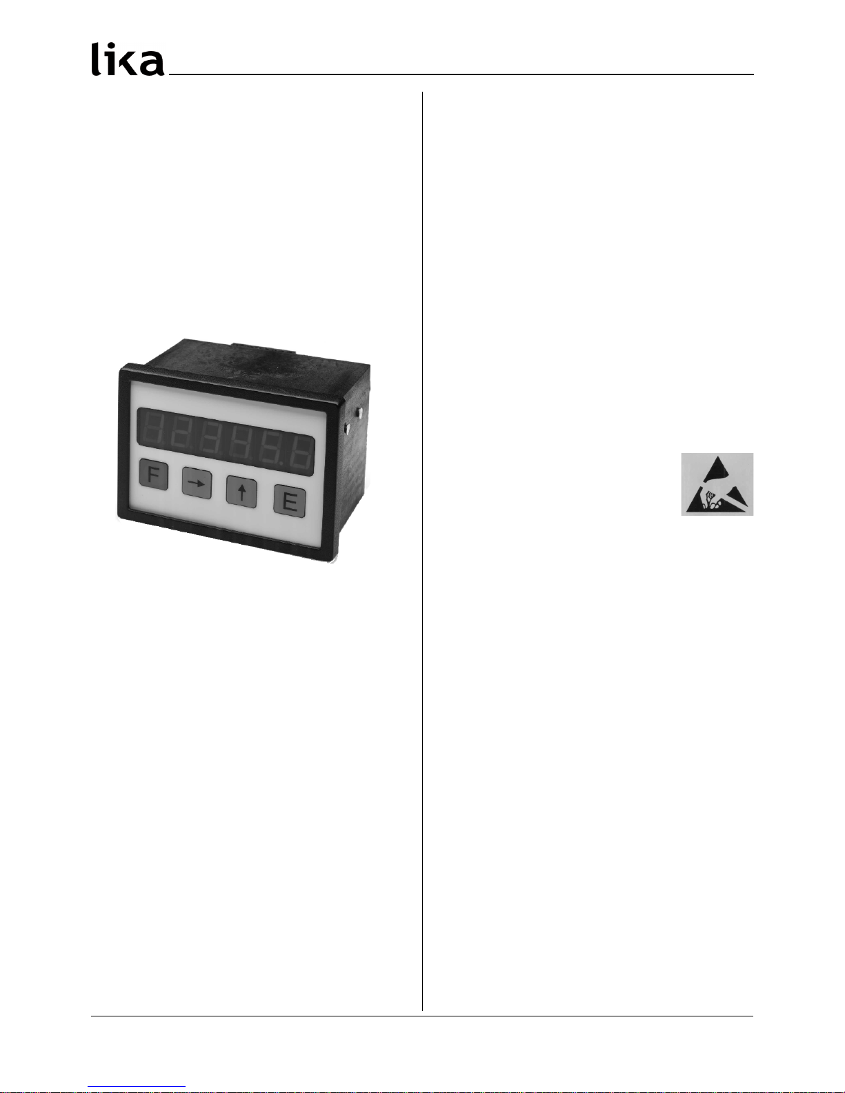
This manual describes the MC150 display series. The
purpose of this device is to display linear or
angular displacements on industrial machines and
automation systems. The device can be connected
to standard Push-Pull or Line Driver incremental
encoders or magnetic sensors.
Chapters
1 Safety summary
2 Identification
3 Installation
4 Mounting recommendations
5 Electrical connections
6 Functions
7 Set up
8 RS232 interface
9 Dimensional drawing and cut-out
1 - Safety summary
For the electrical connections, we recommend to
closely follow these electrical instructions. In
particular, according to the 89/336/EEC norm on
electromagnetic compatibility, following
precautions must be taken:
• Measurement system (sensor) should be
installed as close as possible to the display.
• Always use shielded and twisted cables if
possible.
• Avoid running the sensor cable near high
voltage power cables (e.g. drive cables).
• Install EMC filters on sensor power supply if
needed.
• Avoid mounting sensor near capacitive or
inductive noise sources such as relays, motors,
and switching power supplies.
• Static discharge can damage internal sensitive
electronic components. Before handling and
installing, discharge electrical
charge from your body and tools
which may come in touch with
the device.
Connect according to the chapter 5: “Electrical
connections”.
2 - Identification
The device can be identified by the label's data
(ordering code, serial number). This information is
listed in the delivery document. For technical
features of the product to make reference at the
technical catalogue.
3 - Installation
Install the device according to the protection level
provided. Protect the system against knocks,
friction, solvents and respect the environmental
characteristics of the product.
4 - Mounting recommendations
Push the display into the cut-out (approx. 90 x 66
mm2) without panel clips.
Install panel clips on the display's housing and
screw until fixed.
MAN MC150 I_E 1.7 9 www.lika.it
www.lika.biz
Page 2
+24V / GND
(see P13)
MC150
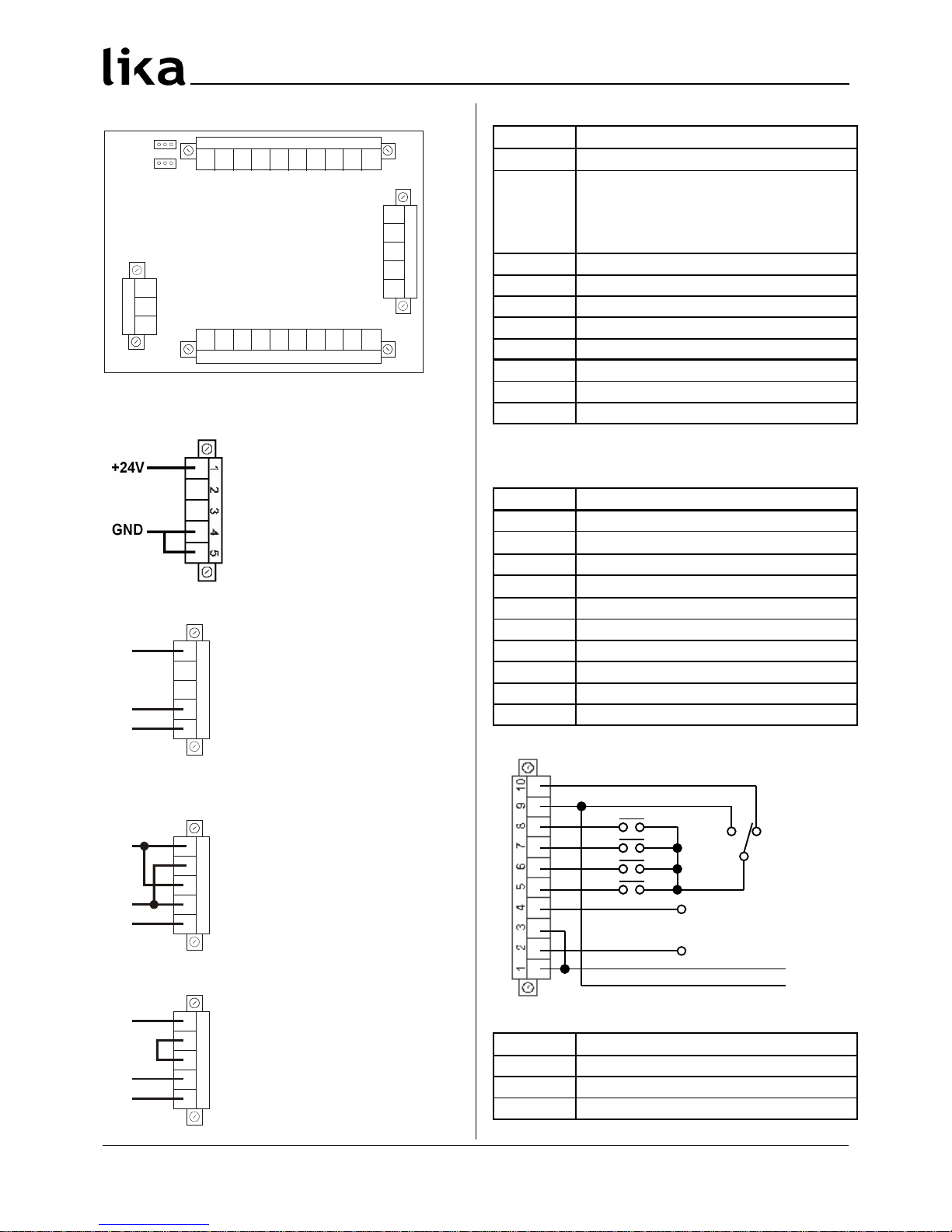
5 - Electrical connections
1 2
3 4 5 6 7 8 9 10
Con1
Con2
Con3
24V 5V
low high
J1
J2
1 2 3
Con4
1 2 3 456 7 8 9 10
1 2
3
4 5
5.1 CON1 connections (power supply)
Power supply 24Vdc
Pin 1 +24Vdc, max. 150 mA
Pin 2 n.c.
Pin 3 n.c.
Pin 4 GND
Pin 5 GND
Power supply 24Vac
1 2
3
4 5
L
N
PE
Pin 1 L
Pin 2 n.c.
Pin 3 n.c.
Pin 4 N, max. 150 mA
Pin 5 P.E.
n.c. = Not connected
Power supply 115Vac
1 2
3
4 5
L
N
PE
Pin 1 L
Pin 2 N
Pin 3 L
Pin 4 N, max. 100 mA
Pin 5 P.E.
Power supply 230Vac
1 2
3
4 5
L
N
PE
Pin 1 L
Pin 2 Connect to pin 3
Pin 3 Connect to pin 2
Pin 4 N, max. 100 mA
Pin 5 P.E.
5.2 CON2 connections (sensor input)
Pin Function
1 *
GND
2 *
+24Vdc (J1: left, power supply: 24Vdc)
+12Vdc (J1: left, power supply: 115Vac
230Vac)
+5Vdc (J1: right, any power supply)
3 A
4 /A (see parameter P22)
5 B
6 /B (see parameter P22)
7 0
8 /0 (see parameter P22)
9 P.E.
10 P.E.
*: output power supply for measuring system
5.3 CON3 connections (Inputs and Outputs)
Pin Function
1 +24Vdc input supply for output 2
2
Output 2 (PNP) *
3 +24Vdc input supply for output 1
4
Output 1 (PNP) *
5 Input 4 - OFFSET function
6 Input 3 - FREEZE/STOP function
7 Input 2 - SET function
8 Input 1 - RESET function
9 GND output for function inputs
10 +24Vdc output for function inputs
*: available only with “MC150-P1-…”
5.4 CON4 connections (RS232)
Pin Function
1 RxD
2 TxD
3 GND
MAN MC150 I_E 1.7 10 www.lika.it
www.lika.biz
Page 3
MC150
5.5 J1 jumper (encoder power supply)
Position Function
Left
+10Vdc +30Vdc *
Right +5Vdc
*: see chapter “5.2 CON2 connections”.
5.6 J2 jumper (input signal level)
Position Function
Left Input connected with GND (CON3/Pin9)
Right
Input connected with +24Vdc
(CON3/Pin10)
6 - Functions
6.1 Start up
At start up the unit shows the software version
followed by actual position.
Software version: SOF xx
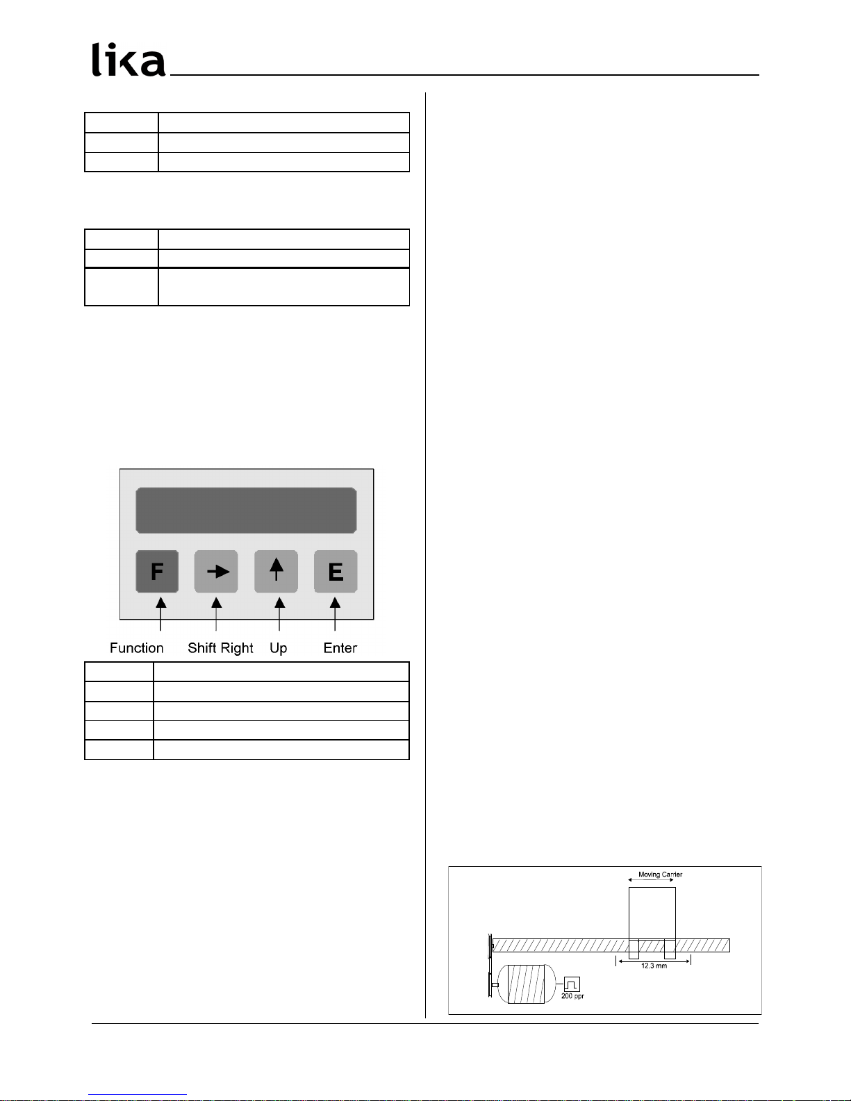
6.2 Key functions
Key Function
F
Function (save + exit setup)
Shift Right (select parameter / digit)
Up (change value)
E
Enter (save + scroll menu)
6.2.1 Default parameter (factory settings)
Default parameter values are written in BOLD
characters. The unit can be reset to default values
by pushing F, and E key while switching on.
6.2.2 Direct functions
To set direct functions, such as reset, reset with
datum value, tool correction (offset value),
absolute/relative display mode and mm/Inch display
mode, program P07 parameter.
7 - Set up
7.1 Access to setup menus
Push F key to enter setup.
• push to select Func 1 or Func 2
• push E to scroll parameters
• push F to exit setup
Admissible value range for each parameter is listed
as follows: [min. value, max. value]
7.2 Parameter setting
In order to activate modified parameters, switch off
and on the device.
Level 1: Func1
P00 Datum value / Eich [-99999, 999999]
Display can be set to datum value (or preset) by
activating SET input or pushing key.
Default value: 50.0
Level 2: Func2
P00 Display value per distance moved [1, 10000]
Enter the value to be displayed when the unit
receives the number of pulses per distance moved
in parameter P01. Note this value is entered
without decimal.
Default value: 100
P01 Nr. of pulses per distance moved [1, 65000]
Enter the number of pulses per distance. This same
distance unit is used to determine the Display value
per distance moved.
Default value: 100
Example:
A ball screw moves 12.3mm per revolution. The
system uses a rotary encoder with 200 PPR (pulses
per revolution).
In this case:
P00 should be set to 123 (value without decimals)
P01 is 200
MAN MC150 I_E 1.7 11 www.lika.it
www.lika.biz
Page 4

MC150
P02 Encoder edge counting mode [1, 3]
1 = x 1 (1 edge counting mode)
2 = x 2 (2 edge counting mode)
3 = x 4 (4 edge counting mode)
For linear magnetic measurement systems set 3.
Example:
A magnetic sensor SME5 with 0,01mm resolution
has to be displayed. The measurement length is
100,00 mm. The sensor outputs 10000 pulses (after
quad.).
P00 is 10000 (100,00mm without decimals)
P01 is 10000 (pulses)
P02 is 3 (signal quadrature)
P03 Counting direction [0, 1]
Sets counting direction of display.
0 = standard counting direction
1 = inverted counting direction
P04 Decimal point [1, 4]
Modification of decimal point position. This setting
has no influence on other parameters.
0 = 000000
1 = 00000.0
….
4 = 00.0000
P05 Password Level 1 [0, 999999]
Enter desired code number here to prevent
operator from entering the "Datum value mode"
(Level 1).
Default value: 0
Attention: Datum value can be set only after
digiting the correct password.
To cancel password and restore default value see
chapter “Default parameter” (6.2.1).
P06 Password Level 2 [0, 999999]
Enter desired code number here to prevent
operator from entering the "Parameter mode"
(Level 2).
Default value: 0
Attention: Datum value can be set only after
digiting the correct password.
To cancel password and restore default value see
chapter “Default parameter” (6.2.1).
P07 Function of the push buttons [0, 6]
The function of the , and the E buttons in
operating mode can be selected.
0 = no functions
1 = E will set actual value to zero
2 = will set actual value to Preset (Func1, P00)
4 = E activates Offset (P12)
8 = will set absolute/incremental mode
16 = E will set Inch/mm mode
To combine more than one function add up the
totals of the different functions and enter the sum
(amount):
3 = function 1 and 2 activated
6 = function 2 and 4 activated
9 = function 1 and 8 activated
11 = function 1, 2 and 8 activated
14 = function 2, 4 and 8 activated
18 = function 2 and 16 activated
P08 Input 1: Reset function [0, 1]
Sets function of Reset input.
0 = static reset. Sets actual value to 0 until input is
activated (high).
1 = dynamic reset. Edge triggered Reset input.
P09 Encoder Index function [0, 2]
Sets function of encoder index pulse 0, /0.
0 = no function
1 = Rising edge triggered Index pulse
2 = Falling edge triggered Index pulse
P10 Input2: SET function [0, 1]
Sets function of SET input.
0 = static SET input. Sets display to Preset value
until input is activated (high).
1 = dynamic SET. Edge triggered SET input.
P11 Input 3:
Freeze/ Stop/ Absolute-incremental function [0, 2]
Sets function of Freeze/Stop input.
0 = freeze actual value while internal counter is
still active.
1 = stop encoder pulse counting.
2 = change absolute/incremental mode
MAN MC150 I_E 1.7 12 www.lika.it
www.lika.biz
Page 5

MC150
P12 Offset [0, 65000]
Value entered here will be subtracted from actual
value by activating OFFSET function (Input 4).
By deactivating OFFSET input, Offset value will be
added to actual value.
Enter the Offset dimension in units of length, such
as xx.x mm or x.xx inches.
Default value: 10.0
P13 Function input configuration [0, 15]
Chose from NO (Normally Open) or NC (Normally
Closed), low active (connected with GND) or high
active (connected with +24Vdc).
P13 CON3
Con. with
GND
Con. with
+24Vdc
Pin 5Pin 6Pin 7Pin
8
0 15 NO NO NO NO
1 14 NC NO NO NO
2 13 NO NC NO NO
3 12 NC NC NO NO
4 11 NO NO NC NO
5 10 NC NO NC NO
6 9 NO NC NC NO
7 8 NC NC NC NO
8 7 NO NO NO NC
9 6 NC NO NO NC
10 5 NO NC NO NC
11 4 NC NC NO NC
12 3 NO NO NC NC
13 2 NC NO NC NC
14 1 NO NC NC NC
15 0 NC NC NC NC
P14 Output 1 [-99999, 999999]
Output 1 will be activated when actual value is
more (or less) than Output 1 value, see P21.
Default value: 10.0
P15 Output 2 [-99999, 999999]
Output 2 will be activated when actual value is
more (or less) than Output 1 value, see P21.
Default value: 20.0
P16 Output configuration [0, 1]
0 = static output
1 = with output dwell time (see P17 and P18)
P17 Output 1 dwell time [0, 2.50]
Enter output dwell time between 0 and 2.50
seconds. P16 must be 1.
Default value: 0
P18 Output 2 dwell time [0, 2.50]
Enter output dwell time between 0 and 2.50
seconds. P16 must be 1.
Default value: 0
P19 Memory on power down [0, 1]
0 = actual value will be stored on power down
1 = after turning power off and on Display shows
"Cal". Display has to be Datumed again before
use (see Func1,P00).
P20 Saw blade offset [-10000, +10000]
Here a value can be stored which is subtracted
from the display value when the Set or Reset
function is activated in incremental mode.
Default value: 0
P21 Output logic [0, 3]
Enter output logic of Output 1 and Output 2.
0 = Output 1 activated when Actual value > P14
Output 2 activated when Actual value > P15
1 = Output 1 activated when Actual value < P14
Output 2 activated when Actual value > P15
2 = Output 1 activated when Actual value > P14
Output 2 activated when Actual value < P15
3 = Output 1 activated when Actual value < P14
Output 2 activated when Actual value < P15
P22 Select CON2 input signals [0, 1]
0 = measuring system with A, B and Z tracks.
1 = measuring system with A, /A, B, /B, Z and /Z
tracks.
MAN MC150 I_E 1.7 13 www.lika.it
www.lika.biz
Page 6
MC150
Setup for devices with RS232 serial interface
(option I1)
P60 Display address [11, 99]
Enter here the serial address of the readout when
using the serial interface option RS232. Don't use
addresses 20, 30, 40,….., 90.
Default value: 11
P61 Baud rate [0, 4]
0 = 2400
1 = 4800
2 = 9600
3 = 19200
4 = 38400
P62 RS232 mode [0, 3]
0 = RS232 protocol according to DIN66019
1 = Printer mode. To transmit actual value
periodically to a printer at a time interval set in
parameter P63.
2 = Printer mode. To transmit actual value to a
printer when pushing E button (attention to
P07: do not use 1, 4 and 16 functions).
3 = Printer mode. To transmit actual value to a
printer when activating Input CON3/ pin 5
(attention: set P12 = 0).
P63 Transmission time interval [0.01, 650.00]
Enter the time interval for periodic actual value
transmission in sec. (P62 must be =1).
Default value: 1.00
P99 Actual value for RS232 [-99999, 999999]
This parameter shows the actual value for serial
transmission via RS232 Interface if parameter
P62=0.
NOTE:
In order to activate modified parameters, switch off
and on the device.
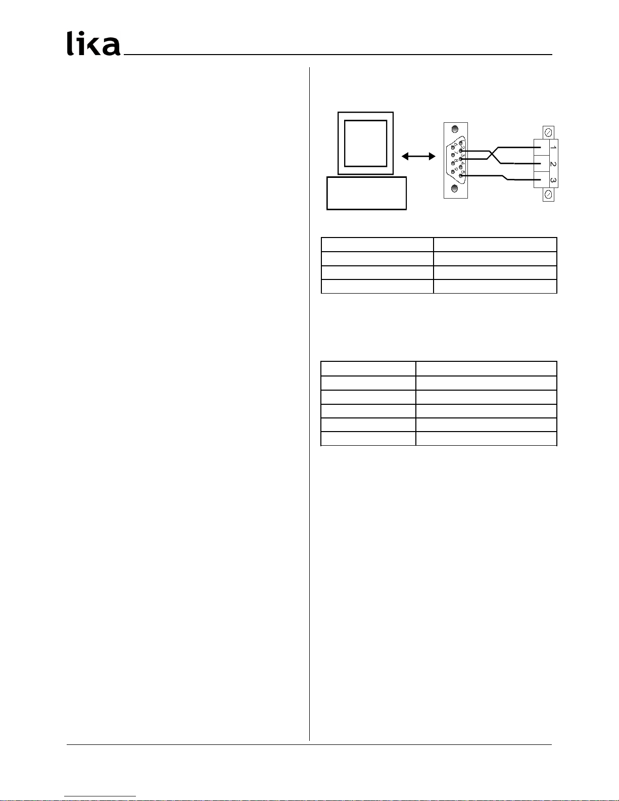
8 - RS232 interface
8.1 PC connection
Use 9 pin DSub connector and connect with CON4
of the MC150 readout.
Pin Function
1 RxD Reception data
2 TxD Transmission data
3 GND Ground
Make sure that RxD on PC side is connected with
TxD on MC150 side and TxD / PC is connected with
RxD / MC150.
8.2 Technical data
Function Data
Baud rate
2400,4800,9600,19200,38400
Data bits 8 bit ASCII
Parity bit No
Stop bit 1
Flow control No
8.3 Communication protocol
The RS232 protocol is according to DIN 66019, ISO
1765, ANSI X3.28.
The PC is the master and the MC150 is the slave
with individual serial address to be entered in
Parameter P60.
There are 3 ways of communication:
• Send
• Receive
• Broadcast
MAN MC150 I_E 1.7 14 www.lika.it
www.lika.biz
Page 7

MC150
8.3.1 Protocol structure
Field Value Function
EOT 04 H End Of Transmit
AD1 ascii Unit address, MSByte
AD2 ascii Unit address, LSByte
STX 02 H Start of TeXt
C1,C2 ascii
Level code = 20 : Level 1
21: Level 2
C3,C4 ascii Parameter code = 00…99
DATA
n byte
ascii
Process data
ETX 03 H End of TeXt
BCC ascii Block Check Character
ENQ 05 H ENQuiry
NAK 15 H Not Acknowledge
ACK 06 H Acknowledge
NOTE:
• BCC (block-check-character) is a character used
for check the correct transmission. It is
generated by XOR-ing characters C1, C2, C3,
C4, DATA and ETX (including). If BCC < 20 Hex,
BCC must be added up with 20 Hex, this avoids
BCC to have values in the range of control
character values.
• DATA field can contain any number of
numerical characters, a sign and can be filled
up with zeros. All DATA are sent in ASCII Code.
8.3.2 Send data from Master to Slave
PC MC150
EOT AD1 AD2 STX C1 C2 C3 C4
DATA ETX BCC
When transmission is correct slave replies with ACK
in any other cases with NAK.
MC150 PC
ACK
or
NAK
All parameters sent to the slave are stored in a data
buffer. Parameters have to be activated by the
"activate parameter" command (see chap. 8.3.4).
Example:
Sets the parameter P01 = 100 (unit address = 11).
PC MC150
EOT AD1 AD2 STX C1 C2 C3 C4
ascii
1 1 2 1 0 1
Hex
04 31 31 02 32 31 30 31
DATA ETX BCC
ascii
1 0 0
Hex
31 30 30 03 30
MC150 PC
ACK
ascii
Hex
06
8.3.3 Receive data from slave
PC MC150
EOT AD1 AD2 STX C1 C2 C3 C4 ENQ
The correct reception of the string is acknowledged
with the following message:
MC150 PC
STX C1 C2 C3 C4 DATA ETX BCC
The reception of a incorrect string is followed by a
negative acknowledgment like:
MC150 PC
STX C1 C2 C3 C4 EOT
in any other cases with “NAK”:
MC150 PC
NAK
Example:
Read actual value (unit address = 11).
PC MC150
EOT AD1 AD2 STX C1 C2 C3 C4 ENQ
ascii
1 1 2 1 9 9
Hex
04 31 31 02 32 31 39 39 05
If actual value = 12 acknowledge message will be:
MC150 PC
STX C1 C2 C3 C4 DATA ETX BCC
ascii
2 1 9 9 1 2
Hex
02 32 31 39 39 31 32 03 23
MAN MC150 I_E 1.7 15 www.lika.it
www.lika.biz
Page 8

MC150
8.3.4 Serial commands
All commands are sent with parameter P52 (C1, C2,
C3, C4 fields = 2152). See “Send data from Master
to Slave” (chap. 8.3.2)
The following commands are available:
- Activate data: DATA=137
- Save data to EEProm: DATA=138
- Set datum: DATA=139
Example:
Send “Activate data” (unit address = 11).
PC MC150
EOT AD1 AD2 STX C1 C2 C3 C4
ascii
1 1 2 1 5 2
Hex
04 31 31 02 32 31 35 32
DATA ETX BCC
ascii
1 3 7
Hex
31 33 37 03 32
MC150 PC
ACK
ascii
Hex
06
8.3.5 Printer mode
When a printer is connected to the MC150 the
following data string will be transmitted:
MC150 printer
AD1 AD2 DATA LF CR
xx xx xx 0A Hex 0D Hex
The MC150 is sending its serial address followed by
the actual value and Line Feed (LF) and Carriage
Return (CR).
9 - Dimensional drawing and cut-out
Check details on product catalogue.
Provide a 90 x 66 mm2 (w x h) cut-out.
Rev HW-SW Man. Vers. Description
0 1.0 1st issue
- 1.- Manual update
6 03-08 1.6 Chap.5, 6, 7 and 8 corrections
7 03-10 1.7
Chap. 5, 8.2 and parameter P62
corrections.
Add parameter P22.
Lika Electronic
Via S. Lorenzo, 25 - 36010 Carrè (VI) - Italy
Tel. +39 0445 382814
Fax +39 0445 382797
Italy: eMail info@lika.it - www.lika.it
World: eMail info@lika.biz - www.lika.biz
MAN MC150 I_E 1.7 16 www.lika.it
www.lika.biz
 Loading...