

Page 1
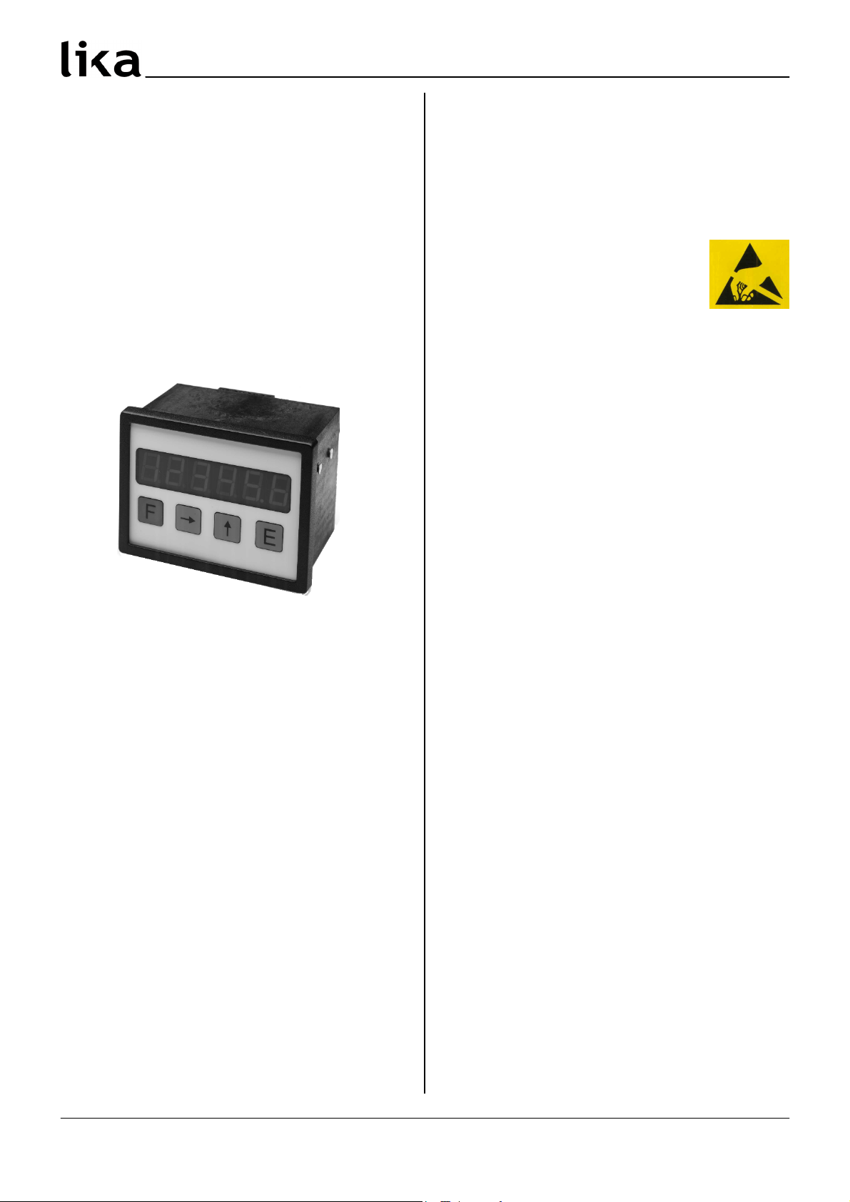
MC111
User manual
MC111
Description
This manual describes the MC111 display series. The
purpose of this device is to display linear or
angular displacements on industrial machines and
automation systems. The device can be connected
to standard Push&Pull incremental encoders or
magnetic sensors (A and B signals).
Chapters
1 Safety summary
2 Identification
3 Installation
4 Mounting recommendations
5 Electrical connections
6 Functions
7 Set up
8 Dimensional drawing and cut&out
1 Safety summary
For the electrical connections, we recommend to
closely follow these electrical instructions. In
particular, according to the 89/336/EEC norm on
electromagnetic compatibility, following
precautions must be taken:
• Measurement system (sensor) should be
installed as close as possible to the display.
• Always use shielded and twisted cables if
possible.
• Avoid running the sensor cable near high
voltage power cables (e.g. drive cables).
• Install EMC filters on sensor power supply if
needed.
• Avoid mounting sensor near capacitive or
inductive noise sources and switching power
supplies.
• static discharge can damage internal sensitive
electronic components. Before handling and
installing, discharge electrical
charge from your body and tools
which may come in touch with
the device.
Connect according to the chapter 5: “Electrical
connections”.
2 Identification
The device can be identified by the label's data
(ordering code, serial number). This information is
listed in the delivery document. For technical
features of the product, refer to the technical
catalogue.
3 Installation
Install the device according to the protection level
provided. Protect the system against knocks,
friction, solvents and respect the environmental
characteristics of the product.
4 Mounting recommendations
Push the display into the cut&out (approx. 92 x 68
mm2) without panel clips.
Install panel clips on the display's housing and
screw until fixed.
MAN MC111 I_E 1.1.doc Pag. 5 www.lika.it
www.lika.biz
Page 2
1
2
3
4
5
6
7
8
910
Con1
MC111
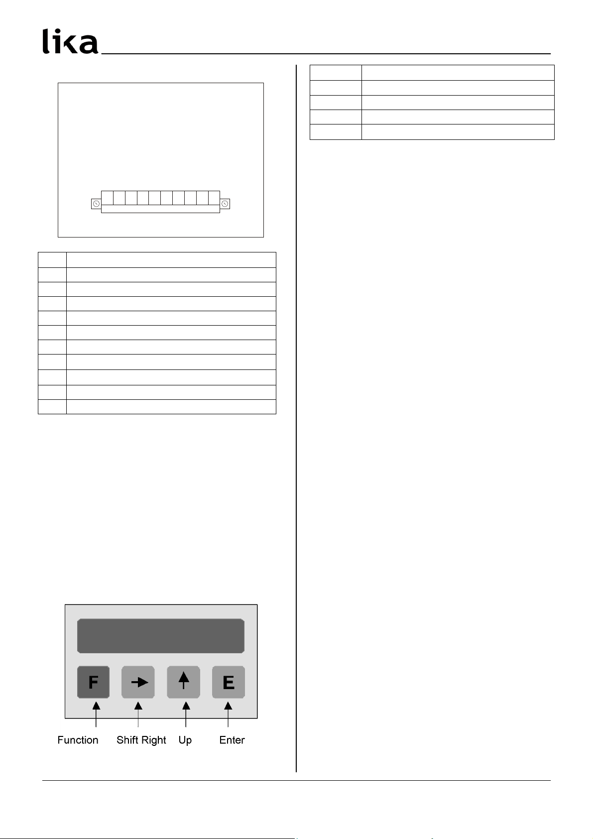
5 Electrical connections
Pin
Function
1 +24Vdc ±10%
2 0Vdc GND
3 A
4 B
5 GND (sensor power supply)
6 +24Vdc (sensor power supply)
7
8
Input 1: Reset / Output 1 *
Input 2: Set / Output 2 *
9 Rectified power supply +
10 Rectified power supply &
*: the outputs are optional (see order code), set
P02 correctly.
Input: 0 ÷ 6.5Vdc = “low active”
8.5 ÷ 30Vdc = “high active”
Output: 24Vdc, 600mA (PNP)
6 Functions
6.1 Start up
At start up the unit shows the software version
followed by actual position.
Software version: SOF xx
6.2 Key functions
Key Function
F Function (save + exit setup)
Shift Right (select parameter / digit)
Up (change value)
E Enter (save + scroll menu)
6.2.1 Default parameter (factory settings)
Default parameter values are written in BOLD
characters. The unit can be reset to default values
by pushing F, and E key while switching on.
6.2.2 Direct functions
To set direct functions, such as reset, reset with
datum value, tool correction (offset value), program
P07 parameter.
7 Set up
7.1 Access to setup menus
Push F key to enter setup.
• push to select Func 1 or Func 2
• push E to scroll parameters
• push F to exit setup
Admissible value range for each parameter is listed
as follows: [min. value, max. value]
7.2 Parameter setting
Level 1: Func1
Eich Datum value / Preset [&99999, 999999]
Display can be set to datum value (or preset) by
activating SET input or pushing key.
Default value: 50.0
Level 2 : Func2
P00 Display value per distance moved [1, 10000]
Enter the value to be displayed when the unit
receives the number of pulses per distance moved
in parameter P01. Note this value is entered
without decimal.
Default value: 100
P01 Nr. of pulses per distance moved [1, 65000]
The display is always set on 4 edge counting mode.
Enter the number of encoder pulses x4 per
distance. This same distance unit is used to
determine the Display value per distance moved.
Default value: 100
MAN MC111 I_E 1.1.doc Pag. 6 www.lika.it
www.lika.biz
Page 3
MC111
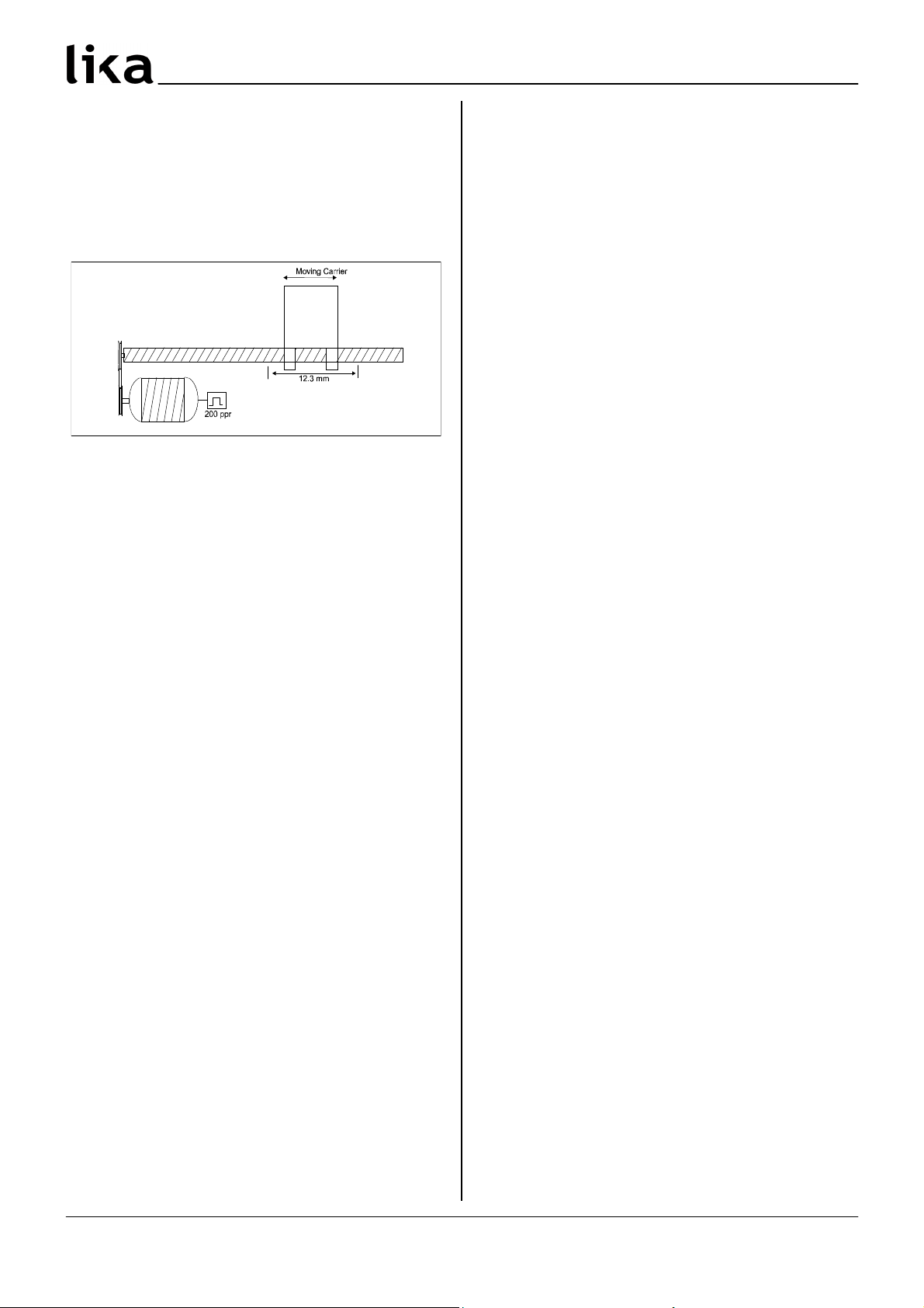
Example:
A ball screw moves 12.3mm per revolution. The
system uses a rotary encoder with 200 PPR (pulses
per revolution).
In this case:
P00 should be set to 123 (value without decimals)
P01 is 800
P02 Input / Output pin [0, 1]
Sets pins 7 and 8 as input or output.
0 = Input
1 = Output (optional, see order code)
P03 Counting direction [0, 1]
Sets counting direction of display.
0 = standard counting direction
1 = inverted counting direction
P04 Decimal point [1, 4]
Modification of decimal point position. This setting
has no influence on other parameters.
0 = 000000
1 = 00000.0
….
4 = 00.0000
P05 Password Level 1 [0, 999999]
Enter desired code number here to prevent
operator from entering the "Datum value mode"
(Level 1).
Default value: 0
Attention: Datum value can be set only after
digiting the correct password.
To cancel password and restore default value see
chapter “Default parameter” (6.2.1).
P06 Password Level 2 [0, 999999]
Enter desired code number here to prevent
operator from entering the "Parameter mode"
(Level 2).
Default value: 0
Attention: Datum value can be set only after
digiting the correct password.
To cancel password and restore default value see
chapter “Default parameter” (6.2.1).
P07 Function of the push buttons [0, 6]
The function of the and the E button in
operating mode can be selected.
0 = no functions
1 = E will set actual value to zero
2 = will set actual value to Datum/Preset (Func1)
3 = both functions 1 + 2
4 = E activates "Saw blade offset" (P12)
6 = both functions 2 + 4
P08 Reset function [0, 1]
Sets function of Reset input (active if P11 = 0).
0 = static reset. Sets actual value to 0 until input is
activated (high).
1 = dynamic reset. Edge triggered Reset input.
P10 Input 2: SET function [0, 1]
Sets function of SET input.
0 = static SET input. Sets display to Preset value
until input is activated (high).
1 = dynamic SET. Edge triggered SET input.
P11 Input 1: Reset / Freeze function [0, 1]
Sets function of Reset / Freeze input.
0 = Input 1: Reset function
1 = Input 1: Freeze function
Reset: see P08
Freeze: freeze actual value while internal counter is
still active. If P11 = 1, than P08 is unused.
P12 Saw blade offset [&50000, 50000]
Value entered here will be added to or subtracted
from actual value by pushing E button (with
P07=2).
Default value: 10.0
MAN MC111 I_E 1.1.doc Pag. 7 www.lika.it
www.lika.biz
Page 4

MC111
P13 Function input configuration [0, 3]
Chose from NO (Normally Open) or NC (Normally
Closed), high active (connected with +24Vdc).
P13 Pin 7 Pin 8
0 NO NO
1 NC NO
2 NO NC
3 NC NC
P14 Output 1 [&99999, 999999]
Output 1 will be activated when actual value is
more than Output 1 value.
Default value: 10.0
P15 Output 2 [&99999, 999999]
Output 2 will be activated when actual value is
more than Output 2 value.
Default value: 20.0
P16 Output configuration [0, 1]
0 = static output
1 = with output dwell time
P17 Output 1 dwell time [0, 2.50]
Enter output 1 dwell time between 0 and 2.50
seconds. P16 must be 1.
Default value: 0.00
P18 Output 2 dwell time [0, 2.50]
Enter output 2 dwell time between 0 and 2.50
seconds. P16 must be 1.
Default value: 0.00
P19 Memory on power down [0, 1]
0 = actual value will be stored on power down
1 = after turning power off and on Display shows
"Eich". Display has to be Datumed again before
use.
P20 Not used
P21 Output logic [0, 3]
Enter output logic of Output 1 and Output 2.
0 = Output 1 activated when Actual value > P14
Output 2 activated when Actual value > P15
1 = Output 1 activated when Actual value > P14
Output 2 activated when Actual value < P15
2 = Output 1 activated when Actual value < P14
Output 2 activated when Actual value > P15
3 = Output 1 activated when Actual value < P14
Output 2 activated when Actual value < P15
P99 Reserved
8 Dimensional drawing and cutout
Check details on product catalogue.
Provide a 92 x 68 mm2 (w x h) cut&out.
Rev SW Man. Vers. Description
0 1 1.0 1st issue
1 2 1.1 Chap.5 update, P21 correction
Lika Electronic
Via S. Lorenzo, 25 & 36010 Carrè (VI) & Italy
Tel. +39 0445 806600
Fax +39 0445 806699
Italy: eMail info@lika.it & www.lika.it
World: eMail info@lika.biz & www.lika.biz
MAN MC111 I_E 1.1.doc Pag. 8 www.lika.it
www.lika.biz
 Loading...