

Page 1
User's guide
LD350
LD355
• Multifunction touch-screen display for incremental encoders
• Speed and position indicator, frequency counter, process meter,
timer, stopwatch, ...
• Input frequencies up to 1MHz
• Digital, analogue, serial and relay outputs
• DC / AC power supply: 18÷30Vdc or 115÷230Vac
Suitable for the following models:
• LD350/LD355 touch-screen display
• LD350/LD355-PM touch-screen display with
115/230Vac power supply
• LD350/LD355-DO touch-screen display with
four control outputs + RS-232 serial
interface
• LD350/LD355-AVI touch-screen display with
analogue output + four control outputs +
RS-232 serial interface
• LD350/LD355-RO touch-screen display with
two relay outputs
General Contents
Preliminary information 10
1 - Safety summary 12
2 - Identification 14
3 - Mounting instructions 15
4 - Electrical connections 17
5 - Display and touch screen 26
6 – Menus and parameters 28
7 - Appendix 74
8 - Parameters / serial codes 75
Lika Electronic • Tel. +39 0445 806600 • info@lika.biz • www.lika.biz
Smart encoders & actuators
Page 2

This publication was produced by Lika Electronic s.r.l. 2018. All rights reserved. Tutti i diritti riservati. Alle Rechte vorbehalten. Todos los
derechos reservados. Tous droits réservés.
This document and information contained herein are the property of Lika Electronic s.r.l. and shall not be reproduced in whole or in
part without prior written approval of Lika Electronic s.r.l. Translation, reproduction and total or partial modification (photostat copies,
film and microfilm included and any other means) are forbidden without written authorisation of Lika Electronic s.r.l.
The information herein is subject to change without notice and should not be construed as a commitment by Lika Electronic s.r.l. Lika
Electronic s.r.l. reserves the right to make all modifications at any moments and without forewarning.
This manual is periodically reviewed and revised. As required we suggest checking if a new or updated edition of this document is
available at Lika Electronic s.r.l.'s website. Lika Electronic s.r.l. assumes no responsibility for any errors or omissions in this document.
Critical evaluation of this manual by the user is welcomed. Your comments assist us in preparation of future documentation, in order
to make it as clear and complete as possible. Please send an e-mail to the following address info@lika.it for submitting your
comments, suggestions and criticisms.
Page 3

General contents
General contents................................................................................................................................................ 3
Subject index....................................................................................................................................................... 7
Typographic and iconographic conventions.................................................................................................9
Preliminary information.................................................................................................................................10
Operational modes.....................................................................................................................................................................10
Functional diagram....................................................................................................................................................................11
1 - Safety summary.........................................................................................................................................12
1.1 Safety........................................................................................................................................................................................12
1.2 Electrical safety....................................................................................................................................................................12
1.3 Mechanical safety...............................................................................................................................................................12
2 - Identification.............................................................................................................................................. 14
3 - Mounting instructions............................................................................................................................. 15
3.1 Overall dimensions..............................................................................................................................................................15
3.2 Installation.............................................................................................................................................................................16
3.3 Cleaning, maintenance and service notes................................................................................................................16
4 - Electrical connections.............................................................................................................................. 17
4.1 DC power supply..................................................................................................................................................................17
4.2 AC power supply (PM order code)...............................................................................................................................18
4.3 Auxiliary voltage output..................................................................................................................................................18
4.4 A, B incremental inputs (LD350 model).....................................................................................................................19
4.4.1 Wiring of the incremental inputs........................................................................................................................19
4.4.2 Note about mechanical switching contacts....................................................................................................19
4.5 A, /A, B, /B incremental inputs (LD355 model).......................................................................................................20
4.5.1 Wiring of the incremental inputs........................................................................................................................20
4.6 Control inputs.......................................................................................................................................................................21
4.6.1 Wiring of the control inputs..................................................................................................................................21
4.6.2 Note about mechanical switching contacts....................................................................................................21
4.7 Analogue output (AVI order code)...............................................................................................................................22
4.8 Serial interface (AVI and DO order codes)................................................................................................................23
4.9 Control outputs (AVI and DO order codes)..............................................................................................................24
4.9.1 Wiring of the control outputs...............................................................................................................................24
4.10 Relay outputs (RO order code)....................................................................................................................................25
4.10.1 Wiring of the relay outputs.................................................................................................................................25
5 - Display and touch screen........................................................................................................................ 26
5.1 Screen structure for parametrization.........................................................................................................................26
5.2 Screen structure during operation..............................................................................................................................27
6 – Menus and parameters............................................................................................................................ 28
6.1 Overview of the structure................................................................................................................................................28
6.2 General menu.......................................................................................................................................................................33
Operational mode...........................................................................................................................................................33
Encoder properties LD350.........................................................................................................................................33
Encoder properties LD355.........................................................................................................................................33
Encoder supply.................................................................................................................................................................34
Counting direction.........................................................................................................................................................34
Scale units...........................................................................................................................................................................34
Linearization mode........................................................................................................................................................35
Page 4

Pin preselection...............................................................................................................................................................36
Pin parameter...................................................................................................................................................................36
Back up memory..............................................................................................................................................................36
Factory settings...............................................................................................................................................................36
6.3 Speed operation mode menu.........................................................................................................................................37
Display value......................................................................................................................................................................37
Base frequency (Hz)......................................................................................................................................................37
Decimal point....................................................................................................................................................................37
Sampling time (s)...........................................................................................................................................................38
Wait time (s)......................................................................................................................................................................38
Standstill time (s)...........................................................................................................................................................39
Average filter....................................................................................................................................................................39
For/Rev detection............................................................................................................................................................39
6.4 Process Time operation mode menu...........................................................................................................................40
Display format..................................................................................................................................................................40
Display value......................................................................................................................................................................40
Base frequency (Hz)......................................................................................................................................................40
Sampling time (s)...........................................................................................................................................................41
Wait time (s)......................................................................................................................................................................41
Standstill time (s)...........................................................................................................................................................42
Average filter....................................................................................................................................................................42
6.5 Timer operation mode menu..........................................................................................................................................43
Time base.............................................................................................................................................................................43
Start / Stop.........................................................................................................................................................................43
Auto set / reset................................................................................................................................................................43
Latch function..................................................................................................................................................................44
Set value.............................................................................................................................................................................. 44
Inc / Dec mode..................................................................................................................................................................44
6.6 Counter operation mode menu....................................................................................................................................45
Count mode........................................................................................................................................................................45
Factor.....................................................................................................................................................................................45
Set value.............................................................................................................................................................................. 46
Decimal point....................................................................................................................................................................46
Batch mode........................................................................................................................................................................46
Batch set value.................................................................................................................................................................47
6.7 Velocity operation mode menu.....................................................................................................................................48
Start / Stop.........................................................................................................................................................................48
Display value......................................................................................................................................................................48
Base time (s)......................................................................................................................................................................48
Decimal point....................................................................................................................................................................48
Wait time (s)......................................................................................................................................................................49
Standstill time (s)...........................................................................................................................................................49
6.8 Preselection values menu................................................................................................................................................50
Preselection 1....................................................................................................................................................................50
Preselection 2....................................................................................................................................................................50
Preselection 3....................................................................................................................................................................50
Preselection 4....................................................................................................................................................................50
6.9 Preselection 1 menu..........................................................................................................................................................51
Mode 1..................................................................................................................................................................................51
Page 5

Hysteresis 1........................................................................................................................................................................53
Pulse time 1 (s)................................................................................................................................................................53
Output target 1...............................................................................................................................................................53
Output polarity 1............................................................................................................................................................53
Output lock 1....................................................................................................................................................................54
Start up delay 1 (s)........................................................................................................................................................54
Event color 1......................................................................................................................................................................54
6.10 Preselection 2 menu........................................................................................................................................................55
Mode 2..................................................................................................................................................................................55
Hysteresis 2........................................................................................................................................................................55
Pulse time 2 (s)................................................................................................................................................................55
Output target 2...............................................................................................................................................................55
Output polarity 2............................................................................................................................................................55
Output lock 2....................................................................................................................................................................55
Start up delay 2 (s)........................................................................................................................................................56
Event color 2......................................................................................................................................................................56
6.11 Preselection 3 menu........................................................................................................................................................57
Mode 3..................................................................................................................................................................................57
Hysteresis 3........................................................................................................................................................................57
Pulse time 3 (s)................................................................................................................................................................57
Output target 3...............................................................................................................................................................57
Output polarity 3............................................................................................................................................................57
Output lock 3....................................................................................................................................................................57
Start up delay 3 (s)........................................................................................................................................................58
Event color 3......................................................................................................................................................................58
6.12 Preselection 4 menu........................................................................................................................................................59
Mode 4..................................................................................................................................................................................59
Hysteresis 4........................................................................................................................................................................59
Pulse time 4 (s)................................................................................................................................................................59
Output target 4...............................................................................................................................................................59
Output polarity 4............................................................................................................................................................59
Output lock 4....................................................................................................................................................................60
Start up delay 4 (s)........................................................................................................................................................60
Event color 4......................................................................................................................................................................60
6.13 Serial menu.........................................................................................................................................................................61
Unit number.......................................................................................................................................................................61
Serial baud rate...............................................................................................................................................................61
Serial format......................................................................................................................................................................61
Serial init.............................................................................................................................................................................62
Serial protocol..................................................................................................................................................................62
Serial timer (s)..................................................................................................................................................................63
Serial value.........................................................................................................................................................................63
6.14 Analog menu......................................................................................................................................................................64
Analog format..................................................................................................................................................................64
Analog start.......................................................................................................................................................................64
Analog end..........................................................................................................................................................................64
Analog gain (%)..............................................................................................................................................................65
Analog offset.....................................................................................................................................................................65
6.15 Command menu...............................................................................................................................................................66
Page 6

Input 1 action...................................................................................................................................................................66
Input 1 config...................................................................................................................................................................68
Input 2 action...................................................................................................................................................................68
Input 2 config...................................................................................................................................................................68
Input 3 action...................................................................................................................................................................68
Input 3 config...................................................................................................................................................................68
6.16 Display menu......................................................................................................................................................................69
Color.......................................................................................................................................................................................69
Brightness (%)..................................................................................................................................................................69
Contrast................................................................................................................................................................................69
Screen saver (s)................................................................................................................................................................69
Up-date time (s)..............................................................................................................................................................70
Font.........................................................................................................................................................................................70
6.17 Linearization menu..........................................................................................................................................................71
P1(X).......................................................................................................................................................................................71
P24(X)....................................................................................................................................................................................71
P1(Y).......................................................................................................................................................................................71
P24(Y)....................................................................................................................................................................................71
6.17.1 Description of the linearisation function.......................................................................................................71
7 - Appendix..................................................................................................................................................... 74
7.1 Data readout via serial interface..................................................................................................................................74
8 - Parameters / serial codes.........................................................................................................................75
8.1 General menu.......................................................................................................................................................................75
8.2 Speed operation mode menu.........................................................................................................................................75
8.3 Process Time operation mode menu...........................................................................................................................76
8.4 Timer operation mode menu..........................................................................................................................................76
8.5 Counter operation mode menu....................................................................................................................................76
8.6 Velocity operation mode menu.....................................................................................................................................77
8.7 Preselection values menu................................................................................................................................................77
8.8 Preselection 1 menu..........................................................................................................................................................77
8.9 Preselection 2 menu..........................................................................................................................................................78
8.10 Preselection 3 menu........................................................................................................................................................78
8.11 Preselection 4 menu........................................................................................................................................................78
8.12 Serial menu.........................................................................................................................................................................79
8.13 Analog menu......................................................................................................................................................................79
8.14 Command menu...............................................................................................................................................................79
8.15 Display menu......................................................................................................................................................................80
8.16 Linearization menu..........................................................................................................................................................80
8.17 Serial codes of commands............................................................................................................................................82
Page 7

Subject index
A
Analog end..........................................................................64
Analog format...................................................................64
Analog gain (%)................................................................65
Analog offset.....................................................................65
Analog start........................................................................64
Auto set / reset..................................................................43
Average filter..............................................................39, 42
B
Back up memory...............................................................36
Base frequency (Hz).................................................37, 40
Base time (s).......................................................................48
Batch mode........................................................................46
Batch set value..................................................................47
Brightness (%)...................................................................69
C
Color......................................................................................69
Contrast................................................................................69
Count mode........................................................................45
Counting direction..........................................................34
D
Decimal point.....................................................37, 46, 48
Display format...................................................................40
Display value.......................................................37, 40, 48
E
Encoder properties LD350............................................33
Encoder properties LD355............................................33
Encoder supply..................................................................34
Event color 1......................................................................54
Event color 2......................................................................56
Event color 3......................................................................58
Event color 4......................................................................60
F
Factor....................................................................................45
Factory settings.................................................................36
Font........................................................................................70
For/Rev detection.............................................................39
H
Hysteresis 1.........................................................................53
Hysteresis 2.........................................................................55
Hysteresis 3.........................................................................57
Hysteresis 4.........................................................................59
I
Inc / Dec mode..................................................................44
Input 1 action....................................................................66
Input 1 config....................................................................68
Input 2 action....................................................................68
Input 2 config....................................................................68
Input 3 action....................................................................68
Input 3 config....................................................................68
L
Latch function...................................................................44
Linearization mode..........................................................35
M
Mode 1..................................................................................51
Mode 2..................................................................................55
Mode 3..................................................................................57
Mode 4..................................................................................59
O
Operational mode............................................................33
Output lock 1.....................................................................54
Output lock 2.....................................................................55
Output lock 3.....................................................................57
Output lock 4.....................................................................60
Output polarity 1.............................................................53
Output polarity 2.............................................................55
Output polarity 3.............................................................57
Output polarity 4.............................................................59
Output target 1.................................................................53
Output target 2.................................................................55
Output target 3.................................................................57
Output target 4.................................................................59
P
P1(X).......................................................................................71
P1(Y).......................................................................................71
P24(X)....................................................................................71
P24(Y)....................................................................................71
Pin parameter....................................................................36
Pin preselection................................................................36
Preselection 1....................................................................50
Preselection 2....................................................................50
Preselection 3....................................................................50
Preselection 4....................................................................50
Pulse time 1 (s)..................................................................53
Pulse time 2 (s)..................................................................55
Pulse time 3 (s)..................................................................57
Pulse time 4 (s)..................................................................59
S
Sampling time (s)......................................................38, 41
Scale units...........................................................................34
Screen saver (s).................................................................69
Serial baud rate.................................................................61
Page 8

Serial format......................................................................61
Serial init..............................................................................62
Serial protocol...................................................................62
Serial timer (s)...................................................................63
Serial value..........................................................................63
Set value.......................................................................44, 46
Standstill time (s)..............................................39, 42, 49
Start / Stop..................................................................43, 48
Start up delay 1 (s)..........................................................54
Start up delay 2 (s)..........................................................56
Start up delay 3 (s)..........................................................58
Start up delay 4 (s)..........................................................60
T
Time base.............................................................................43
U
Unit number.......................................................................61
Up-date time (s)...............................................................70
W
Wait time (s)........................................................38, 41, 49
Page 9
Typographic and iconographic conventions
In this guide, to make it easier to understand and read the text the following typographic and
iconographic conventions are used:
• parameters and objects both of the device and the interface are coloured in GREEN;
• alarms are coloured in RED;
• states are coloured in FUCSIA.
When scrolling through the text some icons can be found on the side of the page: they are expressly
designed to highlight the parts of the text which are of great interest and significance for the user.
Sometimes they are used to warn against dangers or potential sources of danger arising from the use of
the device. You are advised to follow strictly the instructions given in this guide in order to guarantee
the safety of the user and ensure the performance of the device. In this guide the following symbols are
used:
This icon, followed by the word WARNING, is meant to highlight the parts of the
text where information of great significance for the user can be found: user must
pay the greatest attention to them! Instructions must be followed strictly in order
to guarantee the safety of the user and a correct use of the device. Failure to heed
a warning or comply with instructions could lead to personal injury and/or damage
to the unit or other equipment.
This icon, followed by the word NOTE, is meant to highlight the parts of the text
where important notes needful for a correct and reliable use of the device can be
found. User must pay attention to them! Failure to comply with instructions could
cause the equipment to be set wrongly: hence a faulty and improper working of
the device could be the consequence.
This icon is meant to highlight the parts of the text where suggestions useful for
making it easier to set the device and optimize performance and reliability can be
found. Sometimes this symbol is followed by the word EXAMPLE when instructions
for setting parameters are accompanied by examples to clarify the explanation.
Page 10

Preliminary information
This guide is designed to provide the most complete information the operator needs to correctly and
safely install and operate the LD350 and LD355 touch-screen indicator series.
LD350 and LD355 touch-screen indicators are designed to interface HTL/TTL encoders or
NPN/PNP/NAMUR sensors and offer several operating modes such as position indicator, tachometer and
speed indicator, frequency / RPM indicator, process meter, counter, timer, stopwatch, etc. The input
frequency can be up to 1 MHz. They also implement the counting direction and the linearisation
functions.
They feature a touch screen and 7-segment graphic display with a complete set of plain text, symbols
and units. The LED display is bright and provides high contrast readability and also allows the background
light to turn red, green or yellow in the event of the set occurrences such as when the threshold limits
are exceeded. The combination of plain text and touch screen functions make the parametrization very
user-friendly and intuitive.
LD350 touch-screen indicator provides two incremental AB inputs for PNP/NPN/NAMUR/TRI-STATE type
signals.
LD355 touch-screen indicator provides four incremental AB /AB inputs for HTL/RS-422 type signals.
In the series the following models are available:
• LD350 / LD355 touch-screen indicator standard version;
• LD350- / LD355-PM provides additional 115-230Vac power supply;
• LD350- / LD355-AVI provides additional 16-bit analogue output, four control outputs and RS-
232 serial interface;
• LD350- / LD355-DO further offers four control outputs and RS-232 serial interface;
• LD350- / LD355-RO is equipped with two relay outputs.
All options (-PM, -AVI, -DO, -RO) can be freely combined.
For technical specifications please refer to the product datasheet.
To make it easier to read the text, this guide can be divided into two main sections.
In the first section (from section 1 to section 4) general information concerning the safety, the
mechanical installation and the electrical connection.
In the second section (from section 5 to section 8) both general and specific information is given on the
operator menu and the setup procedure.
Operational modes
All functions can be configured in the parameter menu.
The device can be set to one of the following operation modes:
• SPEED (only input A or input B are used, depending on the parameter setting), see the “6.3 Speed
operation mode menu” section on page 37.
◦ Tachometer / speed indicator
Page 11

◦ Measurement of frequency / RMP indicator
◦ Monitoring functions for speed and standstill
• PROCESS TIME (only input A is used), see the “6.4 Process Time operation mode menu” section on
page 40.
◦ Processing time indicator (reciprocal speed)
◦ Baking time indicator
◦ Flow time indicator
• TIMER (only input A or input B are used, depending on the parameter setting), see the “6.5 Timer
operation mode menu” section on page 43
◦ Operation as stopwatch (start / stop function can be freely parametrized)
◦ Counter for working hours
◦ Period measurement
• COUNTER (input A and input B are both used), see the “6.6 Counter operation mode menu”
section on page 45
◦ Pulse counter / sum or differential counter
◦ Up or down counter
◦ Position indicator
◦ Quadrature counter
◦ Batch counter
• VELOCITY (input A operates as a start input and input B operates as a stop input), see the “6.7
Velocity operation mode menu” section on page 48
◦ Runtime measurement as speed indicator
Functional diagram
Page 12

LD350 • LD355
1 - Safety summary
1.1 Safety
• Always adhere to the professional safety and accident prevention
regulations applicable to your country during device installation and
operation;
• installation and maintenance operations have to be carried out by qualified
personnel only, with power supply disconnected and stationary mechanical
parts;
• device must be used only for the purpose appropriate to its design: use for
purposes other than those for which it has been designed could result in
serious personal and/or the environment damage;
• high current, voltage and moving mechanical parts can cause serious or
fatal injury;
• warning ! Do not use in explosive or flammable areas;
• failure to comply with these precautions or with specific warnings
elsewhere in this manual violates safety standards of design, manufacture,
and intended use of the equipment;
• Lika Electronic assumes no liability for the customer's failure to comply
with these requirements.
1.2 Electrical safety
• Turn OFF power supply before connecting the device;
• connect following to explanation in the ”4 - Electrical connections” section
on page 17;
• in compliance with 2014/30/EU norm on electromagnetic
compatibility, following precautions must be taken:
- before handling and installing the equipment, discharge
electrical charge from your body and tools which may come in touch with
the device;
- power supply must be stabilized without noise; install EMC filters on
device power supply if needed;
- always use shielded cables (twisted pair cables whenever possible);
- avoid cables runs longer than necessary;
- avoid running the signal cable near high voltage power cables;
- mount the device as far as possible from any capacitive or inductive noise
source; shield the device from noise source if needed;
- minimize noise by connecting the unit to ground (GND). Make sure that
ground (GND) is not affected by noise. The connection point to ground can
be situated both on the device side and on user’s side. The best solution to
minimize the interference must be carried out by the user.
1.3 Mechanical safety
• Install the device following strictly the information in the “3 - Mounting
instructions” section;
• do not disassemble the unit;
• do not tool the unit;
MAN LD350_LD355 E 1.0.odt 1 - Safety summary 12 of 84
Page 13

LD350 • LD355
• delicate electronic equipment: handle with care;
• do not subject the device to knocks or shocks;
• respect the environmental characteristics of the device.
MAN LD350_LD355 E 1.0.odt 1 - Safety summary 13 of 84
Page 14

LD350 • LD355
2 - Identification
Device can be identified through the order code and the serial number printed
on the label applied to its body. Information is listed in the delivery document
too. Please always quote the order code and the serial number when reaching
Lika Electronic for purchasing spare parts or needing assistance. For any
information on the technical characteristics of the product, refer to the
technical catalogue.
Warning: devices having order code ending with “/Sxxx” may have
mechanical and electrical characteristics different from standard
and be supplied with additional documentation for special
connections (Technical info).
MAN LD350_LD355 E 1.0.odt 2 - Identification 14 of 84
Page 15
LD350 • LD355
3 - Mounting instructions
WARNING
Installation and maintenance operations have to be carried out by qualified
personnel only, with power supply disconnected and mechanical parts
compulsorily in stop.
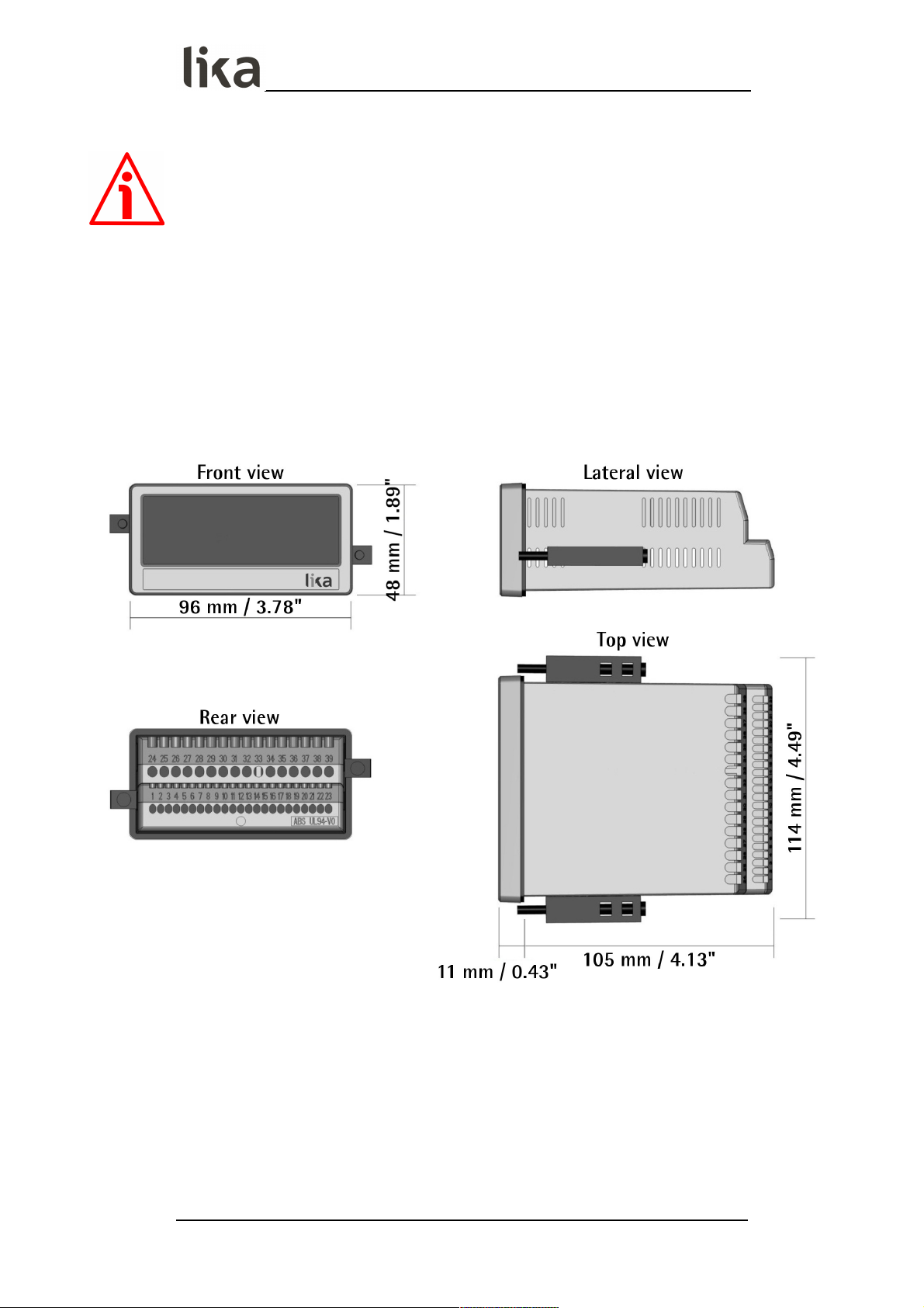
3.1 Overall dimensions
Mount the display into the provided cut-out (w x h approx. 91 x 43 mm, 3.58” x
1.69’’) without panel clips.
Install panel clips on the display housing and screw until the unit is fixed.
Panel cut out: 91 x 43 mm (3.58” x 1.69’’)
MAN LD350_LD355 E 1.0.odt 3 - Mounting instructions 15 of 84
Page 16

LD350 • LD355
3.2 Installation
The device is allowed to be installed and operated only within the permissible
temperature range (-20°C +60°C / -4°F +140°F). Please ensure an adequate
ventilation and avoid any direct contact between the device and gases / liquids.
Before installation or maintenance, the unit must be disconnected from all
voltage sources. Furthermore it must be ensured that no danger can arise in the
event of contact with the disconnected voltage sources.
Devices which are supplied by AC voltages must be connected only by means of
switches or circuit breakers with low voltage circuit. The switch or circuit
breaker must be installed as near as possible to the device and further indicated
as separator.
Incoming as well as outgoing wires and wires for extra low voltages (ELV) must
be separated from dangerous electrical cables (SELV circuits) by using double or
increased insulation.
All selected wires and insulations must comply with the provided voltage and
temperature ranges. Furthermore all country and application specific standards
which are relevant for structure, form and quality of the wires must be ensured.
Indications about the permissible wire cross sections for wiring are described in
the product datasheet.
Before starting the unit for the first time it must be ensured that all connections
and wires are firmly plugged in and secured to the screw terminal blocks. All
terminal blocks (including unused ones) must be fastened by turning the
relevant screws clockwise up to the end position.
Overvoltages at the connections must be limited to values in accordance with
the overvoltage category II.
For placement, wiring, environmental conditions as well as shielding and
earthing/grounding of the supply lines you must comply with the general
standards stated for industrial automation industry and the specific shielding
instructions provided by the manufacturer.
3.3 Cleaning, maintenance and service notes
To clean the unit please just use a slightly damp (not wet!), soft cloth. For the
rear side no cleaning is necessary. For an unscheduled, individual cleaning of the
rear side the maintenance technicians or installation operators are selfresponsible.
During normal operation no maintenance is necessary. In case of unexpected
problems, failures or malfunctions the device must be shipped back to the
manufacturer for any checking, adjustment or repair (if necessary).
Unauthorized opening and repair operations can have negative effects or cause
failures to the protection measures of the unit.
MAN LD350_LD355 E 1.0.odt 3 - Mounting instructions 16 of 84
Page 17
LD350 • LD355
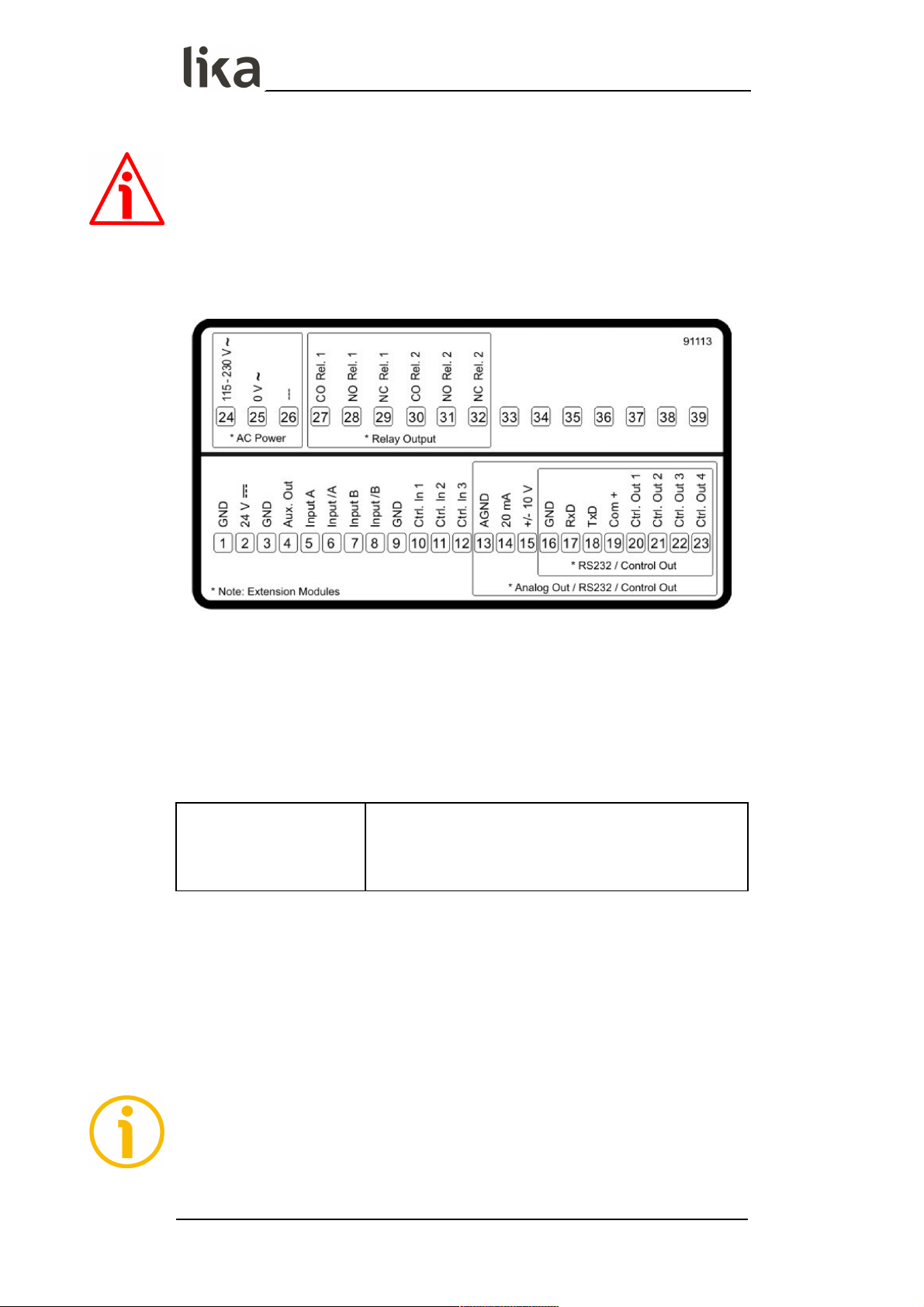
4 - Electrical connections
WARNING
Power supply must be turned off before performing any electrical connection!
The terminal block screws must be tightened using a slotted screwdriver having
a 2 mm wide blade.
4.1 DC power supply
DC power supply technical specifications
Input voltage:
Protection circuit:
Power consumption:
Fuse protection:
18Vdc ... 30Vdc
reverse polarity protection
approx. 100 mA (unloaded)
external fuse T 0.5 A
The unit accepts DC supply from 18 to 30 V through terminal blocks 1 and 2.
The power consumption depends on the level of the supply voltage (approx. 100
mA) and the additional current required by the Auxiliary Voltage output (3 –
GND + 4 – Aux. Out, see the “4.3 Auxiliary voltage output” section on page 18).
All GND terminal blocks are internally connected.
NOTE
For AC power supply (PM order code) see the following section.
MAN LD350_LD355 E 1.0.odt 4 - Electrical connections 17 of 84
Page 18

LD350 • LD355
4.2 AC power supply (PM order code)
AC power supply technical specifications
Input voltage:
Power consumption:
Fuse protection:
115Vac ... 230Vac (50÷60Hz)
approx. 3 VA (unloaded)
external fuse T 0.1 A
The unit with PM order code also accepts AC power supply from 115 V to 230 V
through terminal blocks 24 and 25. The power consumption depends on the
level of the supply voltage (approx. 3 VA) and the additional current required by
the Auxiliary Voltage output (3 – GND + 4 – Aux. Out, see the “4.3 Auxiliary
voltage output” section below).
Devices with PM order code can also be supplied with a DC voltage between 18
V and 30 V through terminals 1 and 2, see the previous “4.1 DC power supply”
section.
4.3 Auxiliary voltage output
Auxiliary voltage output technical specifications (LD350 model)
DC version:
AC version:
24Vdc (approx. 1 V lower than the power supply
voltage), max. 250 mA
24Vdc (±15%), max. 150 mA up to 45°C / 80 mA
when more than 45°C
Auxiliary voltage output technical specifications (LD355 model)
DC version:
AC version:
24Vdc (approx. 1 V lower than the power supply
voltage), max. 250 mA or 5Vdc (±15%), max. 250
mA
24Vdc (±15%) (max. 150 mA up to 45°C / 80 mA
when more than 45°C) or 5Vdc (±15%), max.
250 mA
Terminal blocks 3 and 4 provide an auxiliary output useful for supplying sensors
and encoders.
The output voltage level depends on the power supply.
DC version AC version
The encoder voltage is approx. 1 V lower than the
power supply voltage at terminal blocks 1 and 2
and should be loaded with max. 250 mA.
The encoder voltage is 24 Vdc (± 15%) and should
be loaded with max. 150 mA up to 45° Celsius. At
higher temperature the maximum output current is
reduced to 80 mA.
LD355 model allows the auxiliary voltage output to be set to either 24 Vdc or 5
Vdc. Refer to the Encoder supply parameter in the “6.2 General menu” section
on page 33.
MAN LD350_LD355 E 1.0.odt 4 - Electrical connections 18 of 84
Page 19
LD350 • LD355
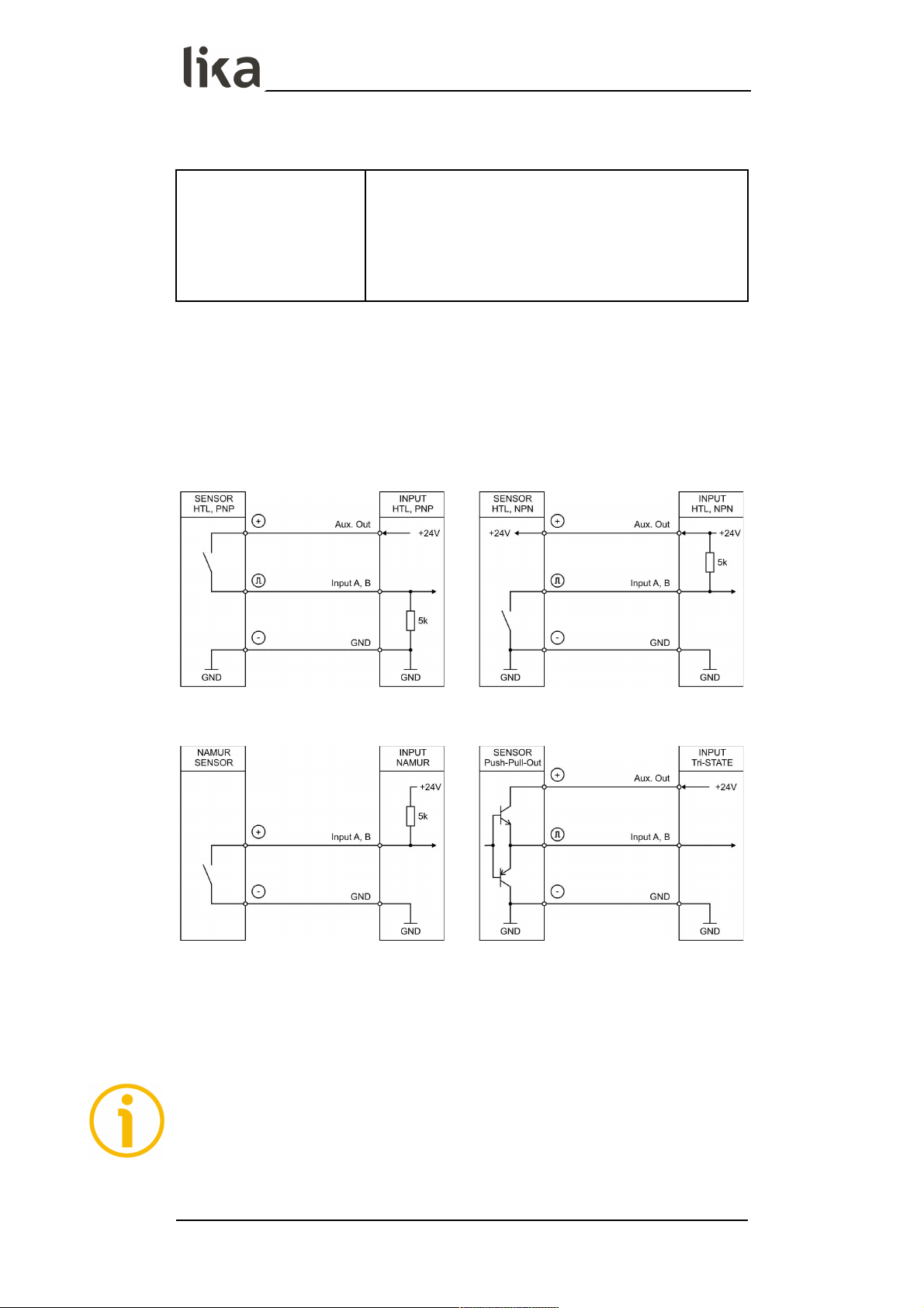
4.4 A, B incremental inputs (LD350 model)
A, B incremental inputs technical specifications
Number of inputs
(channels):
Configuration:
Format:
Frequency:
Load:
2 (A, B)
PNP, NPN, Namur, Tri-State
HTL (Low = 0 … 3 V, High = 9 … 30 V)
max. 250 kHz
max. 6 mA / Ri > 5 kOhm / 470 pF
The unit provides two inputs for HTL signals through terminal blocks 5 and 7.
The characteristics of the incremental inputs (PNP, NPN, Namur or Tri-State) can
be set in the General menu, see the Encoder properties LD350 parameter in
the “6.2 General menu” section on page 33.
4.4.1 Wiring of the incremental inputs PNP NPN
Namur Tri-State
Unconnected PNP inputs are always “LOW” and unconnected NPN inputs are
always “HIGH”.
All inputs are designed to receive impulses from electrical impulse sources.
4.4.2 Note about mechanical switching contacts
When, exceptionally, mechanical contacts are used, please connect an external
capacitor between GND (-) and the corresponding input (+). A capacity of 10 µF
will reduce the input frequency to 20 Hz and miscounting due to contact
bouncing will be eliminated.
MAN LD350_LD355 E 1.0.odt 4 - Electrical connections 19 of 84
Page 20
LD350 • LD355
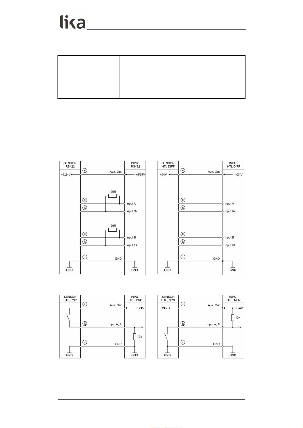
4.5 A, /A, B, /B incremental inputs (LD355 model)
AB, /AB incremental inputs technical specifications
Number of inputs
(channels):
Configuration:
HTL differential:
HTL PNP / NPN:
Load:
4 (A, /A, B, /B)
RS-422, HTL differential, HTL PNP, HTL NPN
HTL (Low = 0 … 3 V, High = 9 … 30 V)
max. 250 kHz
max. 3 mA / Ri > 10 kOhm / 47 pF
The unit provides four pulse inputs at terminal blocks 5, 6, 7 and 8 for HTL/RS422 signals. The characteristics of the incremental inputs can be set in the
General menu, see the Encoder properties LD355 parameter in the “6.2
General menu” section on page 33.
4.5.1 Wiring of the incremental inputs RS-422 HTL differential
HTL PNP, single ended HTL NPN, single ended
Unconnected PNP inputs are always “LOW” and unconnected NPN inputs are
always “HIGH”.
All inputs are designed to receive impulses from electrical impulse sources.
MAN LD350_LD355 E 1.0.odt 4 - Electrical connections 20 of 84
Page 21
LD350 • LD355
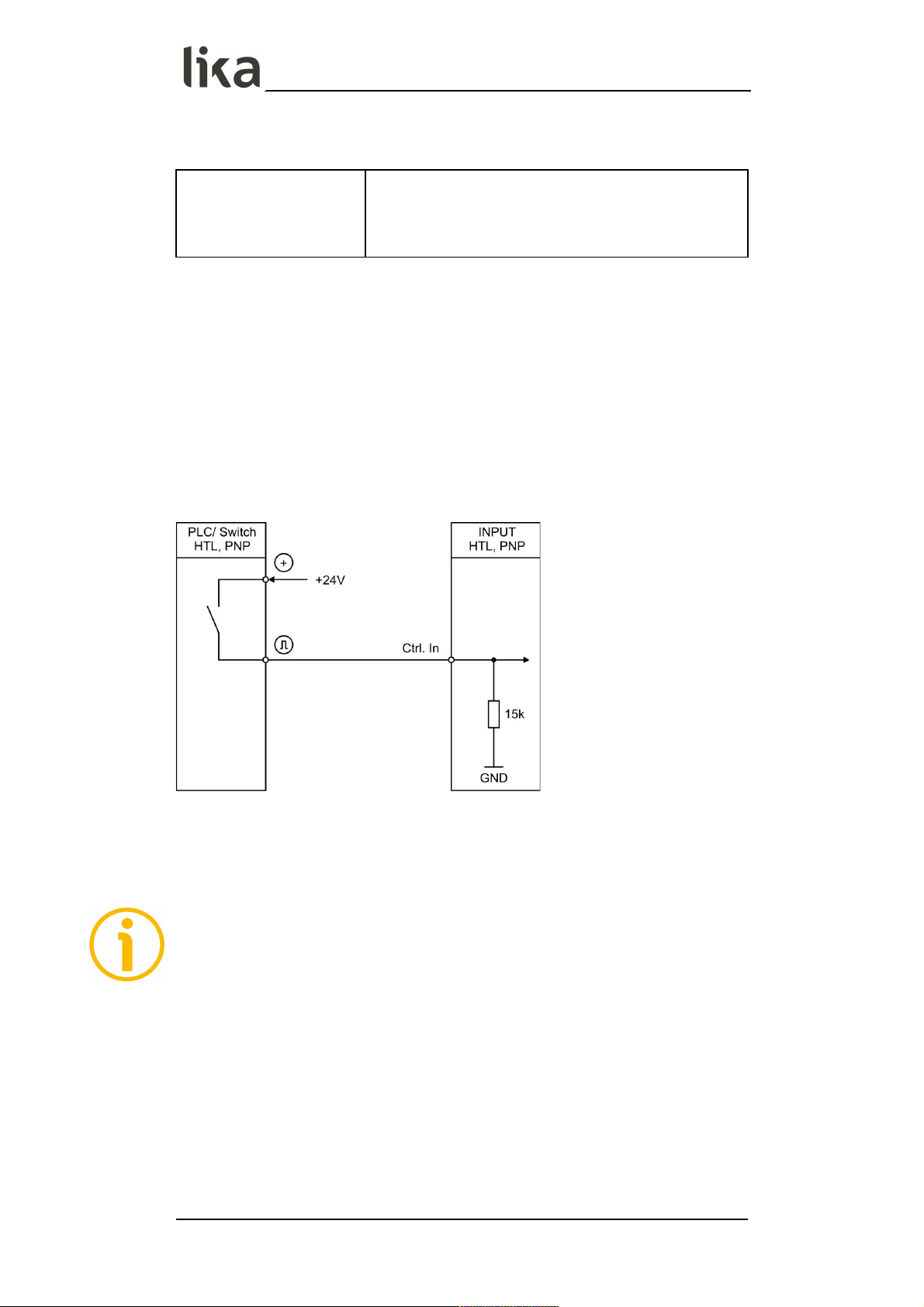
4.6 Control inputs
Control inputs technical specifications
Number of inputs:
Format:
Frequency:
Load:
3
HTL, PNP (Low = 0 … 3 V, High = 9 … 30 V)
max. 10 kHz
max. 2 mA / Ri > 15 kOhm / 470 pF
The three control inputs at terminal blocks 10, 11 and 12 have HTL PNP
characteristics.
In the Command menu (see the “6.15 Command menu” section on page 66) the
operation of the control inputs can be set. Available functions are: reset the
display value, display switching, locking the touch screen or release the lock
function of the control or relay outputs.
4.6.1 Wiring of the control inputs
Unconnected control inputs are always “LOW”.
All inputs are designed to receive impulses from an electronic impulse source.
4.6.2 Note about mechanical switching contacts
When, exceptionally, mechanical contacts are used, please connect an external
capacitor between GND (-) and the corresponding input (+). A capacity of 10 µF
will reduce the input frequency to 20 Hz and miscounting due to contact
bouncing will be eliminated.
MAN LD350_LD355 E 1.0.odt 4 - Electrical connections 21 of 84
Page 22

LD350 • LD355
4.7 Analogue output (AVI order code)
Analogue output technical specifications
Configuration:
Voltage output (0):
Current output (1):
Current output (2):
Resolution:
Accuracy:
Reaction time:
Current or voltage operation
-10 V … +10 V (max. 2 mA)
0 … 20 mA (burden: max. 270 Ohm)
4 … 20 mA (burden: max. 270 Ohm)
16 bits
±0.1%
< 150 ms
A 16 bit analogue output is available through terminal blocks 13 and 14 / 15.
It can be configured and scaled in the Analog menu, see the “6.14 Analog
menu” section on page 64.
The following configurations are available (see the Analog format parameter
on page 64):
0 Voltage output: -10 V … +10 V
1 Current output: 0 … 20 mA
2 Current output: 4 … 20 mA
The analogue output is proportional to the display value and is referenced to
potential AGND.
AGND and GND are internally connected.
WARNING
Voltage and current outputs of the analogue output cannot be operated
simultaneously.
MAN LD350_LD355 E 1.0.odt 4 - Electrical connections 22 of 84
Page 23

LD350 • LD355
4.8 Serial interface (AVI and DO order codes)
Serial interface technical specifications
Format:
Baud rate:
RS-232
9600, 19200 and 38400 baud
A serial interface (RS-232) is available through terminal blocks 16, 17 and 18.
It can be configured in the Serial menu, see the “6.13 Serial menu” section on
page 61.
The RS-232 serial interface can be used:
• for easy setup and commissioning of the unit
• to modify settings and parameters during operation
• to read out internal states and current measuring values via PC or PLC
The following drawing shows the connection to a PC by using a standard D-Sub
9-pin connector:
MAN LD350_LD355 E 1.0.odt 4 - Electrical connections 23 of 84
Page 24
LD350 • LD355
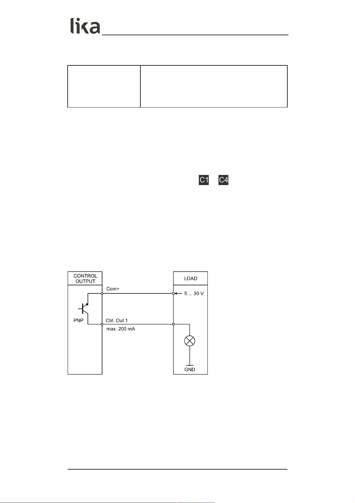
4.9 Control outputs (AVI and DO order codes)
Control outputs technical specifications
Number of outputs:
Format / level:
Output current:
Reaction time:
4
5 … 30 V (depending on the voltage level provided
to terminal block 19 - COM+), PNP
max. 200 mA
< 1 ms
Four control outputs are available at terminal blocks 20, 21, 22 and 23 (+
terminal block 19 for switching voltage).
The switching conditions can be set in the Preselection 1 … Preselection 4
menus, see the “6.9 Preselection 1 menu” … “6.12 Preselection 4 menu” sections
on pages 51, 55, 57 and 59 respectively. The outputs “20 - Ctrl. Out 1”, “21 - Ctrl.
Out 2”, “22 - Ctrl. Out 3” and “23 - Ctrl. Out 4” are fast PNP outputs with a
switching capability of 5÷30 V / 200 mA per channel. The switching states are
displayed (display with unit and status bar) as … , see the “5 - Display
and touch screen” section on page 26.
The switching voltage of the outputs must be applied to input terminal block 19
(COM+).
In case of switching inductive loads it is advisable to use an external filtering of
the coils.
4.9.1 Wiring of the control outputs
MAN LD350_LD355 E 1.0.odt 4 - Electrical connections 24 of 84
Page 25
LD350 • LD355
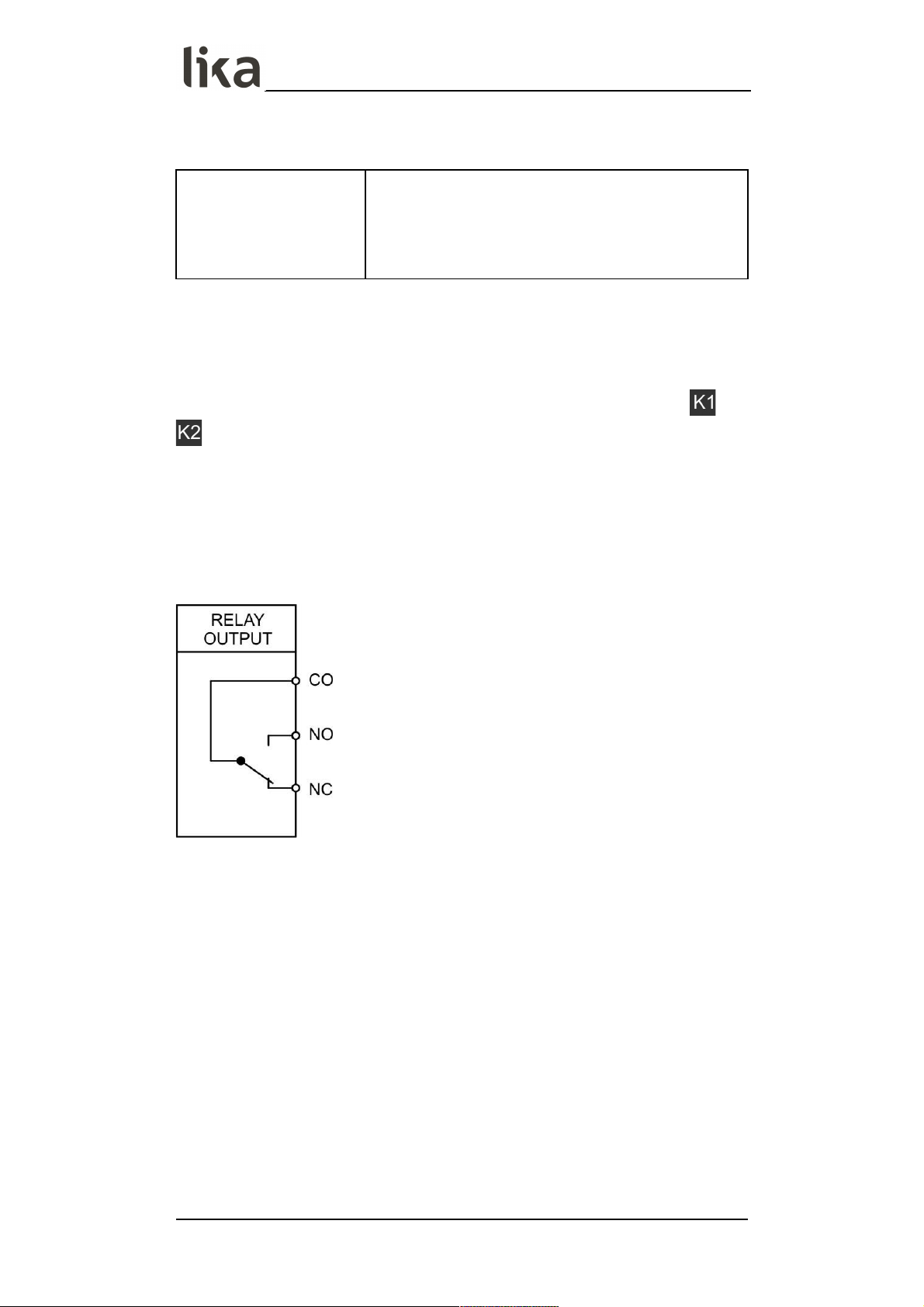
4.10 Relay outputs (RO order code)
Relay outputs technical specifications
Number of outputs:
Configuration:
AC switching capacity:
DC switching capacity:
Reaction time:
2
potential-free changeovers
max. 250 Vac / 3 A / 750 VA
max. 150 Vdc / 2 A / 50 W
< 20 ms
Two relay outputs with potential-free changeover contacts are available at
terminal blocks 27, 28, 29, 30, 31 and 32. The switching conditions can be set in
the Preselection 1 … Preselection 4 menus, see the “6.9 Preselection 1 menu”
… “6.12 Preselection 4 menu” sections on pages 51, 55, 57 and 59 respectively.
The switching states are displayed (display with unit and status bar) as and
, see the “5 - Display and touch screen” section on page 26.
AC switching capacity max. 250 Vac / max. 3 A / 750 VA
DC switching capacity max. 150 Vdc / max. 2 A / 50 W
4.10.1 Wiring of the relay outputs
MAN LD350_LD355 E 1.0.odt 4 - Electrical connections 25 of 84
Page 26
LD350 • LD355
5 - Display and touch screen
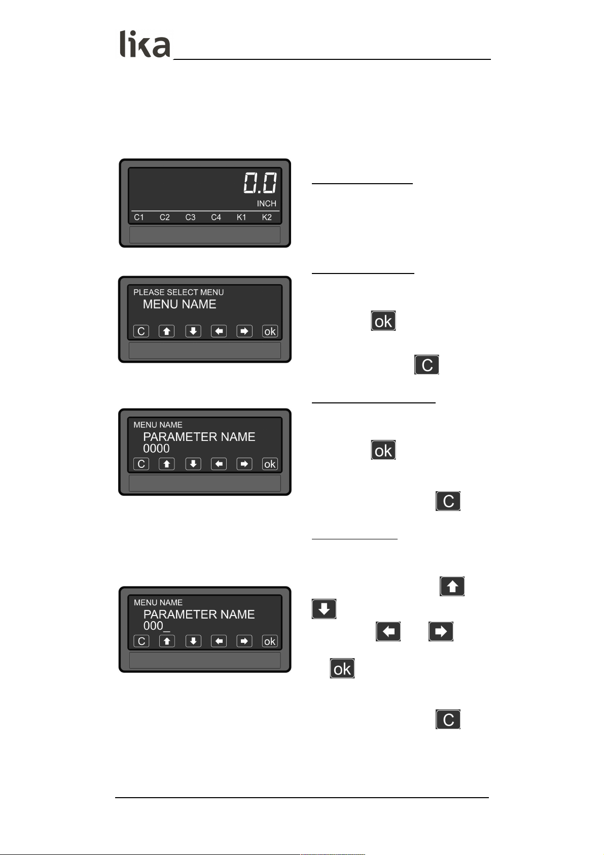
5.1 Screen structure for parametrization
Menus and parameters are described in the “6 – Menus and parameters” section
on page 28.
Start setup procedure
To enter the menus and edit the
parameters, keep the touchscreen
pressed for 3 seconds.
Selection of the menu
Select the menu by pressing the
arrow keys and confirm the choice by
pressing the key.
You can exit the selection of the
menu by pressing the key.
Selection of the parameter
Select the parameter by pressing the
arrow keys and confirm the choice by
pressing the key.
You can exit the selection of the
parameter by pressing the key.
Parameter setting:
After selection the parameter (or its
last digit) starts blinking. Set the
parameter by pressing the and
arrow keys, shift the cursor by
pressing the and arrow
keys and save the value by pressing
the key.
You can exit the editing of the
parameter by pressing the key.
Parameter changes become active only after closing the selection of the
menu.
MAN LD350_LD355 E 1.0.odt 5 - Display and touch screen 26 of 84
Page 27
LD350 • LD355
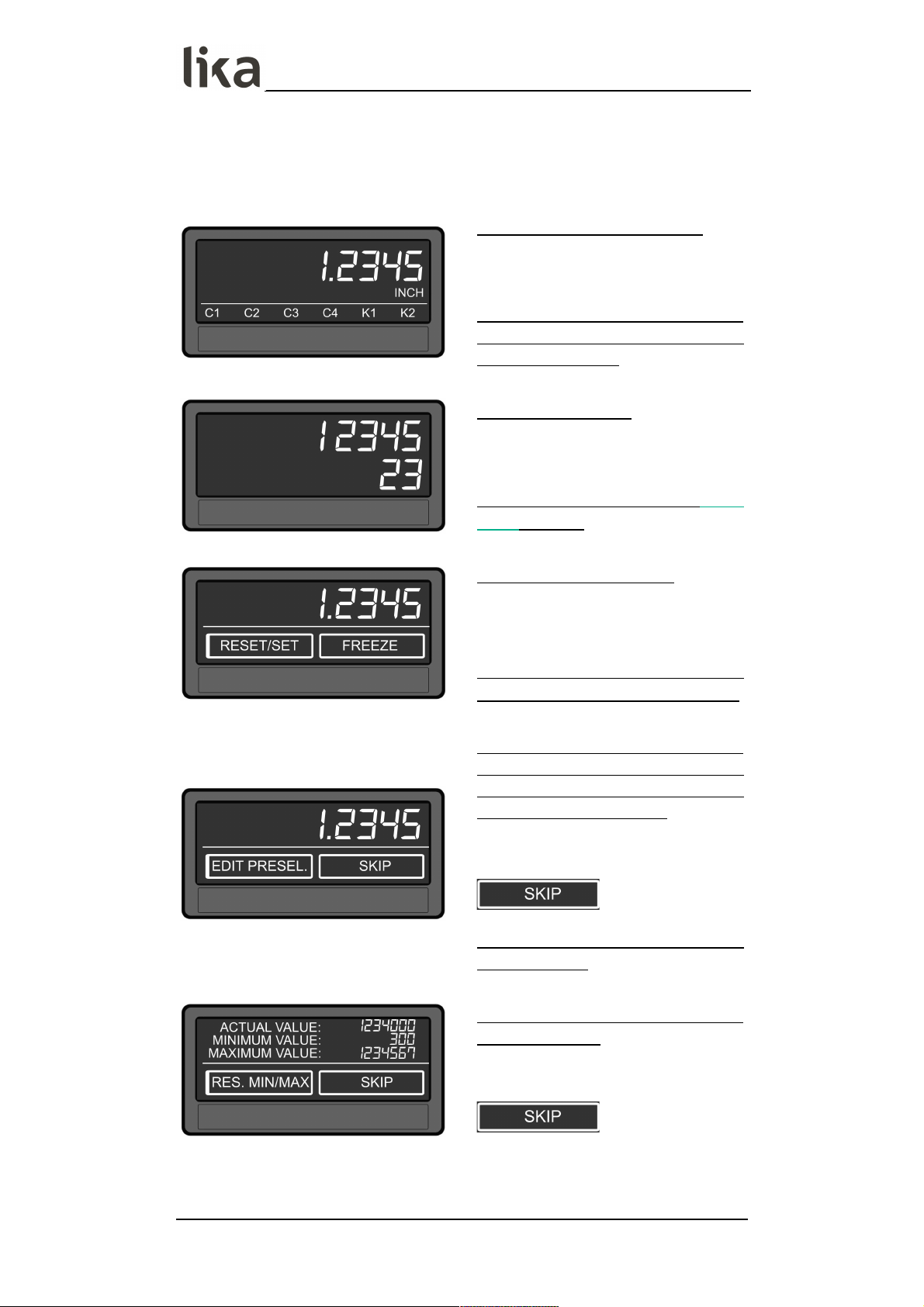
5.2 Screen structure during operation
The following screens are available during operation. Depending on the device
version and the selected operation mode, not all displays will be shown.
Display with unit and status bar
To switch to the next display, press
the touch screen.
Control output states and relay
states are only shown with AVI, DO
and RO order codes.
Display batch counter
To switch to the next display, press
the top half of the screen.
It is available only when the Batch
mode is active.
Display with command keys
To switch to the next display, press
the top half of the screen.
It is available only when the Timer or
Counter operation modes are active .
Display for quick start of the
preselection values setting process
(see the “ 6.8 Preselection values
menu “ section on page 50 )
To switch to the next display, press
the top half of the screen or the
key.
It is available only with AVI, DO and
RO order codes.
Display with current, minimum and
maximum values.
To switch to the next display, press
the top half of the screen or the
key.
MAN LD350_LD355 E 1.0.odt 5 - Display and touch screen 27 of 84
Page 28

LD350 • LD355
6 – Menus and parameters
6.1 Overview of the structure
The following tables offer an overview of the menus and their relevant
parameters. The menu names are printed in bold and the associated parameters
are listed under the menu name. Depending on the device model and the
selected operation mode, only the available menus / parameters are shown.
NOTE
In the pages that describe the menus, the default values are highlighted with
grey background.
General menu, see the “6.2 General menu” section on page 33
Operational mode, see on page 33
Encoder properties LD350, see on page 33 (LD350 model)
or
Encoder properties LD355, see on page 33 (LD355 model)
Encoder supply, see on page 34
Counting direction, see on page 34
Scale units, see on page 34
Linearization mode, see on page 35
Pin preselection, see on page 36
Pin parameter, see on page 36
Back up memory, see on page 36
Factory settings, see on page 36
The following menus depend on the setting of the Operational
mode parameter, see on page 33.
Operational mode = SPEED, Speed operation mode menu, see
the “6.3 Speed operation mode menu” section on page 37
Display value, see on page 37
Base frequency (Hz), see on page 37
Decimal point, see on page 37
Sampling time (s), see on page 38
Wait time (s), see on page 38
Standstill time (s), see on page 39
Average filter, see on page 39
For/Rev detection, see on page 39
MAN LD350_LD355 E 1.0.odt 6 – Menus and parameters 28 of 84
Page 29

LD350 • LD355
Operational mode = PROCESS TIME, Process Time operation
mode menu, see the “6.4 Process Time operation mode menu”
section on page 40
Display format, see on page 40
Display value, see on page 40
Base frequency (Hz), see on page 40
Sampling time (s), see on page 41
Wait time (s), see on page 41
Standstill time (s), see on page 42
Average filter, see on page 42
Operational mode = TIMER, Timer operation mode menu, see
the “6.5 Timer operation mode menu” section on page 43
Time base, see on page 43
Start / Stop, see on page 43
Latch function, see on page 44
Set value, see on page 44
Inc / Dec mode, see on page 44
Operational mode = COUNTER, Counter operation mode menu,
see the “6.6 Counter operation mode menu” section on page 45
Count mode, see on page 45
Factor, see on page 45
Set value, see on page 46
Decimal point, see on page 46
Batch mode, see on page 46
Batch set value, see on page 47
Operational mode = VELOCITY, Velocity operation mode menu,
see the “6.7 Velocity operation mode menu” section on page 48
Start / Stop, see on page 48
Display value, see on page 48
Base time (s), see on page 48
Decimal point, see on page 48
MAN LD350_LD355 E 1.0.odt 6 – Menus and parameters 29 of 84
Page 30

LD350 • LD355
Wait time (s), see on page 49
Standstill time (s), see on page 49
It is only available for devices with order codes AVI, DO or RO.
Preselection values menu, see the “6.8 Preselection values menu” section on
page 50
Preselection 1, see on page 50
Preselection 2, see on page 50
Preselection 3, see on page 50
Preselection 4, see on page 50
It is only available for devices with order codes AVI, DO or RO.
Preselection 1 menu, see the “6.9 Preselection 1 menu” section on page 51
Mode 1, see on page 51
Hysteresis 1, see on page 53
Pulse time 1 (s), see on page 53
Output target 1, see on page 53
Output polarity 1, see on page 53
Output lock 1, see on page 54
Start up delay 1 (s), see on page 54
Event color 1, see on page 54
It is only available for devices with order codes AVI, DO or RO.
Preselection 2 menu, see the “6.10 Preselection 2 menu” section on page 55
Mode 2, see on page 55
Hysteresis 2, see on page 55
Pulse time 2 (s), see on page 55
Output target 2, see on page 55
Output polarity 2, see on page 55
Output lock 2, see on page 55
Start up delay 2 (s), see on page 56
Event color 2, see on page 56
MAN LD350_LD355 E 1.0.odt 6 – Menus and parameters 30 of 84
Page 31

LD350 • LD355
It is only available for devices with order codes AVI, DO or RO.
Preselection 3 menu, see the “6.11 Preselection 3 menu” section on page 57
Mode 3, see on page 57
Hysteresis 3, see on page 57
Pulse time 3 (s), see on page 57
Output target 3, see on page 57
Output polarity 3, see on page 57
Output lock 3, see on page 57
Start up delay 3 (s), see on page 58
Event color 3, see on page 58
It is only available for devices with order codes AVI, DO or RO.
Preselection 4 menu, see the “6.12 Preselection 4 menu” section on page 59
Mode 4, see on page 59
Hysteresis 4, see on page 59
Pulse time 4 (s), see on page 59
Output target 4, see on page 59
Output polarity 4, see on page 59
Output lock 4, see on page 60
Start up delay 4 (s), see on page 60
Event color 4, see on page 60
It is only available for devices with order codes AVI and DO.
Serial menu, see the “6.13 Serial menu” section on page 61
Unit number, see on page 61
Serial baud rate, see on page 61
Serial format, see on page 61
Serial init, see on page 62
Serial protocol, see on page 62
Serial timer (s), see on page 63
Serial value, see on page 63
MAN LD350_LD355 E 1.0.odt 6 – Menus and parameters 31 of 84
Page 32

LD350 • LD355
It is only available for devices with order code AVI.
Analog menu, see the “6.14 Analog menu” section on page 64
Analog format, see on page 64
Analog start, see on page 64
Analog end, see on page 64
Analog gain (%), see on page 65
Analog offset, see on page 65
Command menu, see the “6.15 Command menu” section on page 66
Input 1 action, see on page 66
Input 1 config., see on page 68
Input 2 action, see on page 68
Input 2 config., see on page 68
Input 3 action, see on page 68
Input 3 config., see on page 68
Display menu, see the “6.16 Display menu” section on page 69
Color, see on page 69
Brightness (%), see on page 69
Contrast, see on page 69
Screen saver (s), see on page 69
Up-date time (s), see on page 70
Font, see on page 70
It is only available if the Linearization mode parameter in the General menu
(see on page 35) is set to either “1 – 1 QUADRANT” or “2 – 4 QUADRANT”.
Linearization menu, see the “6.17 Linearization menu” section on page 71
P1(X), see on page 71
...
P24(X), see on page 71
P1(Y), see on page 71
...
P24(Y), see on page 71
MAN LD350_LD355 E 1.0.odt 6 – Menus and parameters 32 of 84
Page 33

LD350 • LD355
6.2 General menu
The default values are highlighted with grey background.
Operational mode
This parameter allows to set the required operational mode, i.e. the desired
measuring function.
0 SPEED
Speed indicator (RPM), tachometer or frequency
counter, see the “6.3 Speed operation mode menu”
section on page 37.
1 PROCESS TIME
Operation as baking time or processing time
indicator (reciprocal speed), see the “6.4 Process
Time operation mode menu” section on page 40.
2 TIMER
Operation as stopwatch, see the “6.5 Timer
operation mode menu” section on page 43.
3 COUNTER
Operation as position indicator, event, sum,
differential or up-down counter, see the “6.6
Counter operation mode menu” section on page 45.
4 VELOCITY
Runtime measurement as speed indicator, see the
“6.7 Velocity operation mode menu” section on
page 48.
Encoder properties LD350
This parameter is only available for LD350 model.
It allows to set the characteristics of the pulse inputs for LD350.
0 PNP
PNP (switch to +)
1 NPN
NPN (switch to -)
2 NAMUR
Connect sensor (–) to GND and sensor (+) to input
(A or B)
3 TRI-STATE
Tri-State for Push-Pull encoders / sensors
Encoder properties LD355
This parameter is only available for LD355 model.
It allows to set the characteristics of the pulse inputs for LD355.
0 RS422
RS-422 standard
1 HTL DIFFERENTIAL
HTL differential
2 HTL PNP
HTL PNP single ended (switch to +)
3 HTL NPN
HTL NPN single ended (switch to -)
MAN LD350_LD355 E 1.0.odt 6 – Menus and parameters 33 of 84
Page 34

LD350 • LD355
Encoder supply
This parameter is only available for LD355 model.
It allows to set the voltage level of the auxiliary voltage output (4 = Aux. Out).
For more information refer to the “4.3 Auxiliary voltage output” section on page
18.
0 24VDC SUPPLY
24 Vdc encoder supply
1 5VDC SUPPLY
5 Vdc encoder supply
Counting direction
This parameter is only available when the Counter operation mode is active, see
the “6.6 Counter operation mode menu” section on page 45.
It allows to set the counting direction: the display will show the count up
information when the encoder rotates clockwise / counter-clockwise (or the axis
moves forward / backward).
0 FORWARD
Clockwise / Forward direction
1 REVERSE
Counter-clockwise / Reverse direction
Scale units
This parameter sets the required engineering unit. It does not affect the
calculation of the display value. The number of decimal places must be set in the
Decimal point parameter that is available in each specific operation mode
menu.
0 Hz Default when Speed operation menu is active
1 kHz
2 m/s
3 m/min
4 km/h
5 mph
6 1/min
7 RPM
8 1/sec
9 RPS
10 Stk/h
11 pcs/h
12 mm
13 m
14 inch
MAN LD350_LD355 E 1.0.odt 6 – Menus and parameters 34 of 84
Page 35

LD350 • LD355
15 feet
16 Stueck
17 pcs
18 sec
Default when Process time, Timer, Counter and
Velocity operation menus are active
19 min
20 Min:Sec
21 H:M:S
22 %
23 l/min
24 gal/min
25 ml/min
26 gr/min
27 inch/min
28 H:M
29 Edit unit
A customized measuring unit with up to 16 digits
can be edited using this parameter.
When you press the key the Edit Unit menu
appears.
A measuring unit can be created using the arrow
keys (by pressing and holding the arrow key down
the characters scroll fast).
Press the key to save the Edit Unit menu.
Press the key to close the Edit Unit menu.
Linearization mode
This parameter activates and sets the linearisation function. See the “6.17
Linearization menu” section on page 71 and the “6.17.1 Description of the
linearisation function” section on page 71.
0 OFF
No linearisation
1 1 QUADRANT
Linearisation using 1 quadrant (see on page 71).
2 4 QUADRANT
Linearisation using 4 quadrants (see on page 71).
MAN LD350_LD355 E 1.0.odt 6 – Menus and parameters 35 of 84
Page 36

LD350 • LD355
Pin preselection
This parameter allows to set the PIN code to lock the quick start of the
Preselection values menu used to enter the preselection values, see the “5.2
Screen structure during operation” section on page 27. Refer also to the “6.8
Preselection values menu” section on page 50. Master PIN is 6079.
This lock function is only useful if used along with the lock function set in the
Pin parameter.
0000
No lock
...
9999
Access after entering PIN Code 9999
Pin parameter
This parameter sets the PIN code for lock function of all parameters. The Master
PIN is 6079.
0000
No lock
...
9999
Parametrization of the unit after entering PIN code
9999
Back up memory
0 NO
No memory backup following a power failure
1 YES
Backup memory following a power failure, the
current values will be saved
Factory settings
At any time you can return all settings to the factory default values.
Default values are highlighted with grey background in this manual.
WARNING
This action will reset all parameters to factory default values and customised
settings will be lost. After reset you will have to repeat your individual set-up
procedure.
0 NO
No default values are loaded
1 YES
Load default values of all parameters
MAN LD350_LD355 E 1.0.odt 6 – Menus and parameters 36 of 84
Page 37

LD350 • LD355
6.3 Speed operation mode menu
When the Operational mode parameter in the General menu is set to 0 =
SPEED (see on page 33), the Speed operation mode menu is available. It allows
to set the unit operation as speed indicator (RPM), tachometer or frequency
meter.
In this operation mode only input A is active or input A and input B with 90°
phase offset for detection of forward / reverse motion.
Display value
Desired value that will be displayed according to the setting of the Base
frequency (Hz) parameter.
00000001
Smallest value
0000100.0
Default value
99999999
Highest value
Base frequency (Hz)
Reference frequency for the desired Display value expressed in Hz.
000001
Smallest value
000100
Default value
500000
Highest value
Decimal point
It sets the position of the decimal point.
0 NO
No decimal point
1 0000000.0
Decimal point placed in the specified position
2 000000.00
Decimal point placed in the specified position
3 00000.000
Decimal point placed in the specified position
4 0000.0000
Decimal point placed in the specified position
5 000.00000
Decimal point placed in the specified position
6 00.000000
Decimal point placed in the specified position
7 0.0000000
Decimal point placed in the specified position
MAN LD350_LD355 E 1.0.odt 6 – Menus and parameters 37 of 84
Page 38

LD350 • LD355
Sampling time (s)
It allows to set the minimum measurement time. This parameter is used as a
filter in case of uneven frequencies. It directly affects the response time of the
unit. The value is expressed in seconds (s).
0.005
Shortest Sampling time
0.100
Default value
9.999
Longest Sampling time
Wait time (s)
This parameter sets the span of time of the lowest frequency, i.e. the time
between two rising edges when the device detects the frequency 0 Hz.
Frequencies whose span of time is longer than the set Wait time (s) will be
evaluated as frequency = 0 Hz. The value is expressed in seconds (s).
0.01
Frequency = 0 Hz, for frequencies below 100 Hz
01.00
Default value
99.99
Frequency = 0 Hz, for frequencies below 0.1 Hz
MAN LD350_LD355 E 1.0.odt 6 – Menus and parameters 38 of 84
Page 39
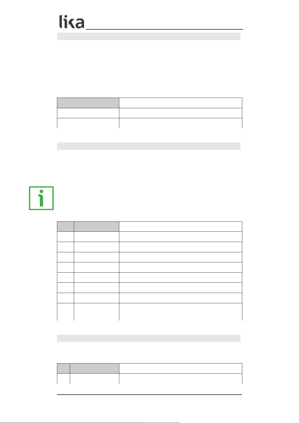
LD350 • LD355
Standstill time (s)
This parameter sets the time after which a standstill condition is acknowledged.
When the “frequency = 0 Hz” condition is detected, after the delay set next to
this parameter the unit warns of the standstill condition and reactivates the
start up delays (see the Start up delay x (s) parameter in the Preselection 1 …
Preselection 4 menus on pages 51, 55, 57 and 59 respectively).
Standstill detection can be set in the Preselection 1 … Preselection 4 menus,
see on pages 51, 55, 57 and 59 respectively.
00.00
Shortest time
…
99.99
Longest time
Average filter
Selectable average or filter function to avoid measuring fluctuations due to
unstable frequencies. With settings 1 to 4 a floating average calculation is
performed. With settings 5 to 8, the device uses an exponential filter. The time
constant T (63%) corresponds to the number of sampling cycles.
EXAMPLE
If Sampling time (s) = 0.1 s and Average filter = “Exponential filter, T (63 %)
= 2x Sampling time (s)”, after 0.2 seconds, 63% of the step size is reached.
0 OFF
No average value will be created
1 2 cycle average
Floating average within 2 cycles
2 4 cycle average
Floating average within 4 cycles
3 8 cycle average
Floating average within 8 cycles
4 16 cycle average
Floating average within 16 cycles
5 2 cycle filter Exponential filter, T (63 %) = 2x Sampling time (s)
6 4 cycle filter Exponential filter, T (63 %) = 4x Sampling time (s)
7 8 cycle filter Exponential filter, T (63 %) = 8x Sampling time (s)
8 16 cycle filter
Exponential filter, T (63 %) = 16x Sampling time
(s)
For/Rev detection
This parameter enables the detection of the direction of rotation (input A, input
B with 90° phase shift).
0 NO
Detection of the direction of rotation OFF
1 YES
Detection of the direction of rotation ON
MAN LD350_LD355 E 1.0.odt 6 – Menus and parameters 39 of 84
Page 40

LD350 • LD355
6.4 Process Time operation mode menu
When the Operational mode parameter in the General menu is set to 1 =
PROCESS TIME (see on page 33), the Process Time operation mode menu is
available. It allows to set the unit operation as baking time or processing time
indicator (reciprocal speed).
Only input A is used.
Display format
This parameter sets the display format for the value. The corresponding decimal
point will be set automatically.
0 SECONDS
Value displayed in seconds
1 MINUTES
Value displayed in minutes
2 MIN:SEC
Value displayed in Minutes : Seconds
3 MIN.00
Value displayed in Minutes . Hundredths of a
minute (1/100)
4 H:M:S
Value displayed in Hours : Minutes : Seconds
Display value
Desired value that will be displayed according to the setting of the Base
frequency (Hz) parameter.
00000001
Smallest value
00001000
Default value
99999999
Highest value
Base frequency (Hz)
Reference frequency for the desired Display value expressed in Hz.
000001
Smallest value
000100
Default value
500000
Highest value
MAN LD350_LD355 E 1.0.odt 6 – Menus and parameters 40 of 84
Page 41

LD350 • LD355
Sampling time (s)
It allows to set the minimum measurement time. This parameter is used as a
filter in case of uneven frequencies. It directly affects the response time of the
unit. The value is expressed in seconds (s).
0.005
Shortest Sampling time
0.100
Default value
9.999
Longest Sampling time
Wait time (s)
This parameter sets the span of time of the lowest frequency, i.e. the time
between two rising edges when the device detects the frequency 0 Hz.
Frequencies whose span of time is longer than the set Wait time (s) will be
evaluated as frequency = 0 Hz. The value is expressed in seconds (s).
00.01
Frequency = 0 Hz, for frequencies below 100 Hz
01.00
Default value
99.99
Frequency = 0 Hz, for frequencies below 0.1 Hz
MAN LD350_LD355 E 1.0.odt 6 – Menus and parameters 41 of 84
Page 42
LD350 • LD355
Standstill time (s)
This parameter sets the time after which a standstill condition is acknowledged.
When the “frequency = 0 Hz” condition is detected, after the delay set next to
this parameter the unit warns of the standstill condition and reactivates the
start up delays (see the Start up delay x (s) parameter in the Preselection 1 …
Preselection 4 menus on pages 51, 55, 57 and 59 respectively).
Standstill detection can be set in the Preselection 1 … Preselection 4 menus,
see on pages 51, 55, 57 and 59 respectively.
00.00
Shortest time
…
99.99
Longest time
Average filter
Selectable average or filter function to avoid measuring fluctuations due to
unstable frequencies. With settings 1 to 4 a floating average calculation is
performed. With settings 5 to 8, the device uses an exponential filter. The time
constant T (63%) corresponds to the number of sampling cycles.
EXAMPLE
If Sampling time (s) = 0.1 s and Average filter = “Exponential filter, T (63 %)
= 2x Sampling time (s)”, after 0.2 seconds, 63% of the step size is reached.
0 OFF
No average value will be created
1 2 cycle average
Floating average within 2 cycles
2 4 cycle average
Floating average within 4 cycles
3 8 cycle average
Floating average within 8 cycles
4 16 cycle average
Floating average within 16 cycles
5 2 cycle filter Exponential filter, T (63 %) = 2x Sampling time (s)
6 4 cycle filter Exponential filter, T (63 %) = 4x Sampling time (s)
7 8 cycle filter Exponential filter, T (63 %) = 8x Sampling time (s)
8 16 cycle filter
Exponential filter, T (63 %) = 16x Sampling time
(s)
MAN LD350_LD355 E 1.0.odt 6 – Menus and parameters 42 of 84
Page 43

LD350 • LD355
6.5 Timer operation mode menu
When the Operational mode parameter in the General menu is set to 2 =
TIMER (see on page 33), the Timer operation mode menu is available. It allows
to set the unit operation as timer or stopwatch.
Depending on the parametrization only input A or both inputs A and B are used.
Time base
This parameter sets the time base or resolution of the measurement.
0 1/1000 SEC
Milliseconds
1 1/100 SEC
Hundredths of a second (1/100)
2 1/10 SEC
Tenths of a second (1/10)
3 SECONDS
Full seconds
4 MIN.00
Minutes and hundredths of a minute (1/100)
5 MIN.0
Minutes and tenths of a minute (1/10)
6 H:M:S
Hours : Minutes : Seconds (9999:59:59)
7 H:M
Hours : Minutes (999999:59)
Start / Stop
This parameter sets the start/stop condition of the time measurement.
0 COUNT AT A HIGH
Time measurement is active as long as input A
signal is “HIGH“
1 COUNT AT A LOW
Time measurement is active as long as input A
signal is “LOW“
2 START A / STOP B
A rising edge of input A signal starts the time
measurement; a rising edge of input B signal stops
the time measurement
3 PERIODE AT A
Time period measurement: the span of time
between two rising edges of input A signal is
displayed
Auto set / reset
0 NO
Time measurement operates by adding up or
subtracting measured values (see the Inc / Dec
mode parameter in the next page), no automatic
set / reset operation is carried out at next start.
Start setting must be done via set / reset (see “6.15
Command menu“ section on page 66)
MAN LD350_LD355 E 1.0.odt 6 – Menus and parameters 43 of 84
Page 44

LD350 • LD355
1 YES
At each start, the new time measurement
automatically starts from the value set next to the
Set value parameter (see the next page)
Latch function
0 NO
Real time display, the counting value appears on
the display
1 YES
The display shows the result of the last
measurement; the current measurement is shown
in the background
Set value
In case of a set / reset command (via keyboard shortcut, control input or PC user
interface), the timer is preset to the value entered next to this item. See also the
Auto set / reset parameter in the previous page.
00000.000
Smallest value (Reset)
…
99999999
Highest value
Inc / Dec mode
It sets the time measurement operation by adding or subtracting measured
values. When the Start / Stop parameter is set to 3 = PERIODE AT A (period
time measurement), the time measurement always operates by adding
measured values.
0
INCREMENT
MODE
Time measurement operates by adding measured
values
1
DECREMENT
MODE
Time measurement operates by subtracting
measured values
MAN LD350_LD355 E 1.0.odt 6 – Menus and parameters 44 of 84
Page 45

LD350 • LD355
6.6 Counter operation mode menu
When the Operational mode parameter in the General menu is set to 3 =
COUNTER (see on page 33), the Counter operation mode menu is available. It
allows to set the unit operation as position indicator, impulse counter, 2 inputs
sum counter, 2 inputs differential counter or up-down counter.
Input A and input B are both used.
Count mode
This parameter allows to set the counter operational mode.
0 A SINGLE
Input A is used as counting input. Input B is
used to set the counting direction: “LOW“ =
Clockwise / Forward direction; “HIGH“ =
Counter-clockwise / Reverse direction
1 A + B
Sum counter: A channel pulses + B channel pulses
2 A - B
Differential counter: A channel pulses – B channel
pulses
3 A/B 90 x1
Quadrature counter: Pulses A, B with edge counting
x1
4 A/B 90 x2
Quadrature counter: Pulses A, B with edge counting
x2
5 A/B 90 x4
Quadrature counter: Pulses A, B with edge counting
x4
Factor
It sets the scaling factor. When the sum counter mode (Count mode = 1 = A +
B) or the differential counter mode (Count mode = 2 = A - B) are set, please
note that the pulse scaling factor will only affect input A.
EXAMPLE
If Factor is set to 1.23456, 100,000 input pulses will result in a value of 123456.
00.00001
Smallest value
01.00000
Default value
99.99999
Highest value
MAN LD350_LD355 E 1.0.odt 6 – Menus and parameters 45 of 84
Page 46

LD350 • LD355
Set value
In case of a reset command (via keyboard shortcut, control input, or PC user
interface), the counter is set to the value entered next to this item.
-99999999
Smallest value
+00000000
Default value
+99999999
Highest value
Decimal point
This parameter sets the position of the decimal point.
0 NO
No decimal point
1 0000000.0
Decimal point placed in the specified position
2 000000.00
Decimal point placed in the specified position
3 00000.000
Decimal point placed in the specified position
4 0000.0000
Decimal point placed in the specified position
5 000.00000
Decimal point placed in the specified position
6 00.000000
Decimal point placed in the specified position
7 0.0000000
Decimal point placed in the specified position
Batch mode
It allows to set the batch counter.
The function of batch counting according to a preset value (Preselection 1 ...
Preselection 3) is only possible if the switch conditions “automatic reset to
zero” (7 = RESULT >= PRES->0) or “set the counter value” (8 = RESULT<=0>SET) are enabled.
Preselection 4 value is the preset value of the batch counter, when the Batch
mode is active.
EXAMPLE
We need the batch counter to increment by 1 at each 1,000 pulses.
Preselection 1 parameter has to be set to “1000”; the corresponding switch
condition Mode 1 has to be set to "7 = RESULT>=PRES->0"; Batch mode has
to be set to “1 = INCREMENT BATCH”. Should an output be turned on after a
batch amount of 33, Preselection 4 has to be set to “33” and the switching
condition of Mode 4 has to be set to “display value greater than or equal to” (3
= RESULT>=PRES).
0 OFF
No batch counter
MAN LD350_LD355 E 1.0.odt 6 – Menus and parameters 46 of 84
Page 47

LD350 • LD355
1
INCREMENT
BATCH
Batch counter operates by incrementing
2
DECREMENT
BATCH
Batch counter operates by decrementing
3 USE INPUTS ONLY
The batch counter is operated only via external
commands (see the Command menu, refer to the
“6.15 Command menu” section on page 66)
Batch set value
In case of a reset / set command (via keyboard, control input or PC user
interface) the batch counter is set to the value entered next to this item. The
parameter is available only when the Batch mode is active.
00000000
Smallest value
…
99999999
Highest value
MAN LD350_LD355 E 1.0.odt 6 – Menus and parameters 47 of 84
Page 48

LD350 • LD355
6.7 Velocity operation mode menu
When the Operational mode parameter in the General menu is set to 4 =
VELOCITY (see on page 33), the Velocity operation mode menu is available. It
allows to set the unit operation as runtime measurement for speed.
Channel A is the start input while channel B is the stop input.
Start / Stop
This parameter sets the start and stop condition.
0 RISE TO RISE
Start = rising edge of input A signal
Stop = rising edge of input B signal
1 FALL TO FALL
Start = falling edge of input A signal
Stop = falling edge of input B signal
2 RISE TO FALL
Start = rising edge of input A signal
Stop = falling edge of input B signal
3 FALL TO RISE
Start = falling edge of input A signal
Stop = rising edge of input B signal
Display value
Desired value that will be displayed according to the setting of the Base time
(s) parameter.
00000001
Smallest value
00001000
Default value
99999999
Highest value
Base time (s)
Reference time for the desired Display value expressed in seconds.
000.001
Smallest value
001.000
Default value
999.999
Highest value
Decimal point
This parameter sets the position of the decimal point.
0 NO
No decimal point
1 0000000.0
Decimal point placed in the specified position
2 000000.00
Decimal point placed in the specified position
3 00000.000
Decimal point placed in the specified position
MAN LD350_LD355 E 1.0.odt 6 – Menus and parameters 48 of 84
Page 49

LD350 • LD355
4 0000.0000
Decimal point placed in the specified position
5 000.00000
Decimal point placed in the specified position
6 00.000000
Decimal point placed in the specified position
7 0.0000000
Decimal point placed in the specified position
Wait time (s)
This parameter sets the span of time of the lowest frequency, i.e. the time
between two rising edges when the device detects the frequency 0 Hz.
Frequencies whose span of time is longer than the set Wait time (s) will be
evaluated as frequency = 0 Hz. The value is expressed in seconds (s).
00.00
The display value is retained until a new value is
available
00.01
Frequency = 0 Hz, for frequencies below 100 Hz
…
99.99
Frequency = 0 Hz, for frequencies below 0.1 Hz
Standstill time (s)
This parameter sets the time after which a standstill condition is acknowledged.
When the “frequency = 0 Hz” condition is detected, after the delay set next to
this parameter the unit warns of the standstill condition and reactivates the
start up delays (see the Start up delay x (s) parameter in the Preselection 1 …
Preselection 4 menus on pages 51, 55, 57 and 59 respectively).
Standstill detection can be set in the Preselection 1 … Preselection 4 menus,
see on pages 51, 55, 57 and 59 respectively.
Standstill time (s) makes sense only if Wait time (s) parameter is different
from 00.00.
00.00
Shortest time
…
99.99
Longest time
MAN LD350_LD355 E 1.0.odt 6 – Menus and parameters 49 of 84
Page 50

LD350 • LD355
6.8 Preselection values menu
The Preselection values menu is used to set the preselection values or the
switching points.
The preselection values / switching points are always referred to the display
value.
This menu is only available for devices with order codes AVI, DO or RO.
Preselection 1
Preselection / switching point 1. The features of Preselection 1 must be set in
the Preselection 1 menu, see “6.9 Preselection 1 menu” section on page 51.
-9999999.9
Smallest value
+0000100.0
Default value
+9999999.9
Highest value
Preselection 2
Preselection / switching point 2. The features of Preselection 2 must be set in
the Preselection 2 menu, see “6.10 Preselection 2 menu” section on page 55.
-9999999.9
Smallest value
+0000200.0
Default value
+9999999.9
Highest value
Preselection 3
Preselection / switching point 3. The features of Preselection 3 must be set in
the Preselection 3 menu, see “6.11 Preselection 3 menu” section on page 57.
-9999999.9
Smallest value
+0000300.0
Default value
+9999999.9
Highest value
Preselection 4
Preselection / switching point 4. The features of Preselection 4 must be set in
the Preselection 4 menu, see “6.12 Preselection 4 menu” section on page 59.
When the Batch mode is active (see on page 46), Preselection 4 value is the
preset value of the batch counter.
-9999999.9
Smallest value
+0000400.0
Default value
+9999999.9
Highest value
MAN LD350_LD355 E 1.0.odt 6 – Menus and parameters 50 of 84
Page 51

LD350 • LD355
6.9 Preselection 1 menu
The Preselection 1 menu is only available for devices with order codes AVI, DO
and RO. It allows to set the characteristics of Preselection 1.
Mode 1
Switching conditions for Preselection 1. The output / relay / display switches
under the following conditions:
0 |RESULT|>=|PRES|
The absolute display value is greater than or equal
to the absolute value of Preselection 1.
If Hysteresis 1 is greater than 0, the following
switching condition is applied:
Display value Preselection 1 ON
Display value < Preselection 1 – Hysteresis 1
OFF
1 |RESULT|<=|PRES|
The absolute display value is less than or equal to
the absolute value of Preselection 1 (start up
suppression – see the Start up delay 1 (s)
parameter on page 54- is advisable).
If Hysteresis 1 is greater than 0, the following
switching condition is applied:
Display value Preselection 1 ON
Display value > Preselection 1 + Hysteresis 1
OFF
2 |RESULT|=|PRES|
The absolute display value is equal to the absolute
value of Preselection 1.
A range (Preselection 1 +/- ½ Hysteresis 1) can
be defined and monitored along with a hysteresis
value.
If Hysteresis 1 is greater than 0, the following
switching condition is applied:
Display value > Preselection 1 + ½ Hysteresis 1
OFF
Display value < Preselection 1 - ½ Hysteresis 1
OFF
3 RESULT >= PRES
Display value is greater than or equal to
Preselection 1, e.g. an overspeed id detected.
If Hysteresis 1 is greater than 0, the following
switching condition is applied:
Display value Preselection 1 ON
Display value < Preselection 1 – Hysteresis 1
OFF
4 RESULT <= PRES
Display value is less than or equal to Preselection
1, e.g. an underspeed is detected (start up
suppression -see the Start up delay 1 (s)
parameter on page 54- is advisable).
If Hysteresis 1 is greater than 0, the following
MAN LD350_LD355 E 1.0.odt 6 – Menus and parameters 51 of 84
Page 52

LD350 • LD355
switching condition is applied:
Display value Preselection 1 ON
Display value > Preselection 1 + Hysteresis 1
OFF
5 RESULT = PRES
Display value is equal to Preselection 1. A range
(Preselection 1 +/- ½ Hysteresis 1) can be defined
and monitored along with a hysteresis value.
If Hysteresis 1 is greater than 0, the following
switching condition is applied:
Display value > Preselection 1 + ½ Hysteresis 1
OFF
Display value < Preselection 1 - ½ Hysteresis 1
OFF
6 RESULT = 0
Display value is zero (standstill condition detected
after the Standstill time (s) delay has expired), e. g.
standstill monitoring. It is only available when
Speed or Process Time operation modes are
selected (see on pages 37 and 40 respectively).
7 RESULT>= PRES->0
Auto reset at Preselection 1. It is only available
when Timer or Counter operation modes are
selected (see on pages 43 and 45 respectively).
Display value is greater than or equal to
Preselection 1, the display value is set to 0.
If Batch mode is active (see on page 46), the batch
counter increments or decrements when the display
value is set to 0.
8 RESULT<= 0->SET
Auto set to Preselection 1. It is only available when
Timer or Counter operation modes are selected
(see on pages 43 and 45 respectively).
Display value is less than or equal to 0, the display
value is set to Preselection 1.
If Batch mode is active (see on page 46), the batch
counter increments or decrements when the display
value is set to Preselection 1.
9 RES>=PRES-TRAIL
Trailing Preselection 1:
Display value is greater than or equal to
Preselection 2 – Preselection 1 ON
Preselection 1 is the trailing preselection from
Preselection 2.
MAN LD350_LD355 E 1.0.odt 6 – Menus and parameters 52 of 84
Page 53

LD350 • LD355
Hysteresis 1
This parameter sets the switching hysteresis of the switch-off point for
Preselection 1 value.
000.0
No switching hysteresis
…
99999
Switching hysteresis = 99999
Pulse time 1 (s)
Duration of the output pulse for the switching condition of Preselection 1
value.
00.000
No output pulse (static signal)
…
60.000
Pulse duration = 60 seconds
Output target 1
Assignment of an output or relay for the switching condition of Preselection 1
value.
If more than one switching condition is assigned to the output / relay, the
output is set when one switching condition at least is true.
0 NO
No switching condition assigned
1 CTRL OUT 1
Switching condition assigned to “20 - Ctrl. Out 1”
2 CTRL OUT 2
Switching condition assigned to “21 - Ctrl. Out 2”
3 CTRL OUT 3
Switching condition assigned to “22 - Ctrl. Out 3”
4 CTRL OUT 4
Switching condition assigned to “23 - Ctrl. Out 4”
5 RELAY 1
Switching condition assigned to “27-28-29 - Rel. 1”
6 RELAY 2
Switching condition assigned to “30-31-32 - Rel. 2”
Output polarity 1
Polarity for the switching condition of Preselection 1.
0 ACTIVE HIGH
Switching condition is true Active “HIGH“
1 ACTIVE LOW
Switching condition is true Active “LOW“
MAN LD350_LD355 E 1.0.odt 6 – Menus and parameters 53 of 84
Page 54

LD350 • LD355
Output lock 1
Latch for the switching condition of Preselection 1.
0 NO No latch for Preselection 1
1 YES
Latch for Preselection 1 (command 4 - LOCK
RELEASE -see the Input 1 action parameter on
page 66- will clear the latch).
Start up delay 1 (s)
Start up suppression for the switching condition of Preselection 1.
This adjustment only applies to the switching conditions 1 - |RESULT|<=|
PRES| and 4 - RESULT<=PRES (see the Mode 1 parameter on page 51) and
when Speed or Process Time operation modes are selected (see on pages 37
and 40 respectively).
00.000
No start up suppression
…
60.000
Start up suppression expressed in seconds
NOTE
Start up delay 3 (s) and Start up delay 4 (s) (see on pages 58 and 60
respectively) have an automatic start up suppression.
Event color 1
Event-depending change of colour of the display for the switching condition of
Preselection 1. Event color 1 has the lowest priority. Event color 2, Event
color 3 and Event color 4 are allowed to overwrite this change of colour.
0 NO CHANGE
No change of colour
1 CHANGE TO RED
Colour of display changes to red
2
CHANGE TO
GREEN
Colour of display changes to green
3
CHANGE TO
YELLOW
Colour of display changes to yellow
MAN LD350_LD355 E 1.0.odt 6 – Menus and parameters 54 of 84
Page 55

LD350 • LD355
6.10 Preselection 2 menu
The Preselection 2 menu is only available for devices with order codes AVI, DO
and RO. It allows to set the characteristics for Preselection 2.
Mode 2
Switching conditions for Preselection 2. The output / relay / display switches
under the following conditions:
0 … 8
For complete information on the switching
conditions 0 … 8, please refer to the Mode 1
parameter in the “6.9 Preselection 1 menu” section
on page 51.
9 RES>=PRES-TRAIL
Trailing Preselection 2:
Display value is greater than or equal to
Preselection 1 – Preselection 2 ON
Preselection 2 is the trailing preselection from
Preselection 1.
Hysteresis 2
This parameter sets the switching hysteresis of the switch-off point for
Preselection 2 value. For complete information please refer to the Hysteresis 1
parameter in the “6.9 Preselection 1 menu” section on page 51.
Pulse time 2 (s)
Duration of the output pulse for the switching condition of Preselection 2
value. For complete information please refer to the Pulse time 1 (s) parameter
in the “6.9 Preselection 1 menu” section on page 51.
Output target 2
Assignment of an output or relay for the switching condition of Preselection 2
value. For complete information please refer to the Output target 1 parameter
in the “6.9 Preselection 1 menu” section on page 51.
Output polarity 2
Polarity for the switching condition of Preselection 2. For complete
information please refer to the Output polarity 1 parameter in the “6.9
Preselection 1 menu” section on page 51.
Output lock 2
Latch for the switching condition of Preselection 2. For complete information
please refer to the Output lock 1 parameter in the “6.9 Preselection 1 menu”
section on page 51.
MAN LD350_LD355 E 1.0.odt 6 – Menus and parameters 55 of 84
Page 56

LD350 • LD355
Start up delay 2 (s)
Start up suppression for the switching condition of Preselection 2. For
complete information please refer to the Start up delay 1 (s) parameter in the
“6.9 Preselection 1 menu” section on page 51.
NOTE
Start up delay 3 (s) and Start up delay 4 (s) (see on pages 58 and 60
respectively) have an automatic start up suppression.
Event color 2
Event-depending change of colour of the display for the switching condition of
Preselection 2. Event color 2, Event color 3 and Event color 4 have the
highest priority and are allowed to overwrite the change of colour set next to
the Event color 1 parameter. For complete information please refer to the
Event color 1 parameter in the “6.9 Preselection 1 menu” section on page 51.
MAN LD350_LD355 E 1.0.odt 6 – Menus and parameters 56 of 84
Page 57

LD350 • LD355
6.11 Preselection 3 menu
The Preselection 3 menu is only available for devices with order codes AVI, DO
and RO. It allows to set the characteristics for Preselection 3.
Mode 3
Switching conditions for Preselection 3. The output / relay / display switches
under the following conditions:
0 … 8
For complete information on the switching
conditions 0 … 8, please refer to the Mode 1
parameter in the “6.9 Preselection 1 menu” section
on page 51.
9 RES>=PRES-TRAIL
Trailing Preselection 3:
Display value is greater than or equal to
Preselection 4 – Preselection 3 ON
Preselection 3 is the trailing preselection from
Preselection 4.
Hysteresis 3
This parameter sets the switching hysteresis of the switch-off point for
Preselection 3 value. For complete information please refer to the Hysteresis 1
parameter in the “6.9 Preselection 1 menu” section on page 51.
Pulse time 3 (s)
Duration of the output pulse for the switching condition of Preselection 3
value. For complete information please refer to the Pulse time 1 (s) parameter
in the “6.9 Preselection 1 menu” section on page 51.
Output target 3
Assignment of an output or relay for the switching condition of Preselection 3
value. For complete information please refer to the Output target 1 parameter
in the “6.9 Preselection 1 menu” section on page 51.
Output polarity 3
Polarity for the switching condition of Preselection 3. For complete
information please refer to the Output polarity 1 parameter in the “6.9
Preselection 1 menu” section on page 51.
Output lock 3
Latch for the switching condition of Preselection 3. For complete information
please refer to the Output lock 1 parameter in the “6.9 Preselection 1 menu”
section on page 51.
MAN LD350_LD355 E 1.0.odt 6 – Menus and parameters 57 of 84
Page 58

LD350 • LD355
Start up delay 3 (s)
Start up suppression for the switching condition of Preselection 3.
This adjustment only applies to the switching conditions 1 - |RESULT|<=|
PRES| and 4 - RESULT<=PRES (see the Mode 3 parameter on page 57) and
when Speed or Process Time operation modes are selected (see on pages 37
and 40 respectively).
0 OFF
No start up suppression
1 AUTO
Automatic start up suppression, until the
preselection value / switching point is exceeded for
the first time.
NOTE
Start up delay 1 (s) and Start up delay 2 (s) (see on pages 54 and 56
respectively) have a time-dependent start up suppression.
Event color 3
Event-depending change of colour of the display for the switching condition of
Preselection 3. Event color 2, Event color 3 and Event color 4 have the
highest priority and are allowed to overwrite the change of colour set next to
the Event color 1 parameter. For complete information please refer to the
Event color 1 parameter in the “6.9 Preselection 1 menu” section on page 51.
MAN LD350_LD355 E 1.0.odt 6 – Menus and parameters 58 of 84
Page 59

LD350 • LD355
6.12 Preselection 4 menu
The Preselection 4 menu is only available for devices with order codes AVI, DO
and RO. If Batch mode is active (see the “6.6 Counter operation mode menu”
section on page 45), the batch counter is compared with the Preselection 4
value.
Mode 4
Switching conditions for Preselection 4. The output / relay / display switches
under the following conditions:
0 … 8
For complete information on the switching
conditions 0 … 8, please refer to the Mode 1
parameter in the “6.9 Preselection 1 menu” section
on page 51.
9 RES>=PRES-TRAIL
Trailing Preselection 4:
Display value is greater than or equal to
Preselection 3 – Preselection 4 ON
Preselection 4 is the trailing preselection from
Preselection 3.
Hysteresis 4
This parameter sets the switching hysteresis of the switch-off point for
Preselection 4 value. For complete information please refer to the Hysteresis 1
parameter in the “6.9 Preselection 1 menu” section on page 51.
Pulse time 4 (s)
Duration of the output pulse for the switching condition of Preselection 4
value. For complete information please refer to the Pulse time 1 (s) parameter
in the “6.9 Preselection 1 menu” section on page 51.
Output target 4
Assignment of an output or relay for the switching condition of Preselection 4
value. For complete information please refer to the Output target 1 parameter
in the “6.9 Preselection 1 menu” section on page 51.
Output polarity 4
Polarity for the switching condition of Preselection 4. For complete
information please refer to the Output polarity 1 parameter in the “6.9
Preselection 1 menu” section on page 51.
MAN LD350_LD355 E 1.0.odt 6 – Menus and parameters 59 of 84
Page 60

LD350 • LD355
Output lock 4
Latch for the switching condition of Preselection 4. For complete information
please refer to the Output lock 1 parameter in the “6.9 Preselection 1 menu”
section on page 51.
Start up delay 4 (s)
Start up suppression for the switching condition of Preselection 4.
This adjustment only applies to the switching conditions 1 - |RESULT|<=|
PRES| and 4 - RESULT<=PRES (see the Mode 4 parameter on page 59) and
when Speed or Process Time operation modes are selected (see on pages 37
and 40 respectively).
0 OFF
No start up suppression
1 AUTO
Automatic start up suppression, until the
preselection value / switching point is exceeded for
the first time.
NOTE
Start up delay 1 (s) and Start up delay 2 (s) (see on pages 54 and 56
respectively) have a time-dependent start up suppression.
Event color 4
Event-depending change of colour of the display for the switching condition of
Preselection 4. Event color 2, Event color 3 and Event color 4 have the
highest priority and are allowed to overwrite the change of colour set next to
the Event color 1 parameter. For complete information please refer to the
Event color 1 parameter in the “6.9 Preselection 1 menu” section on page 51.
MAN LD350_LD355 E 1.0.odt 6 – Menus and parameters 60 of 84
Page 61
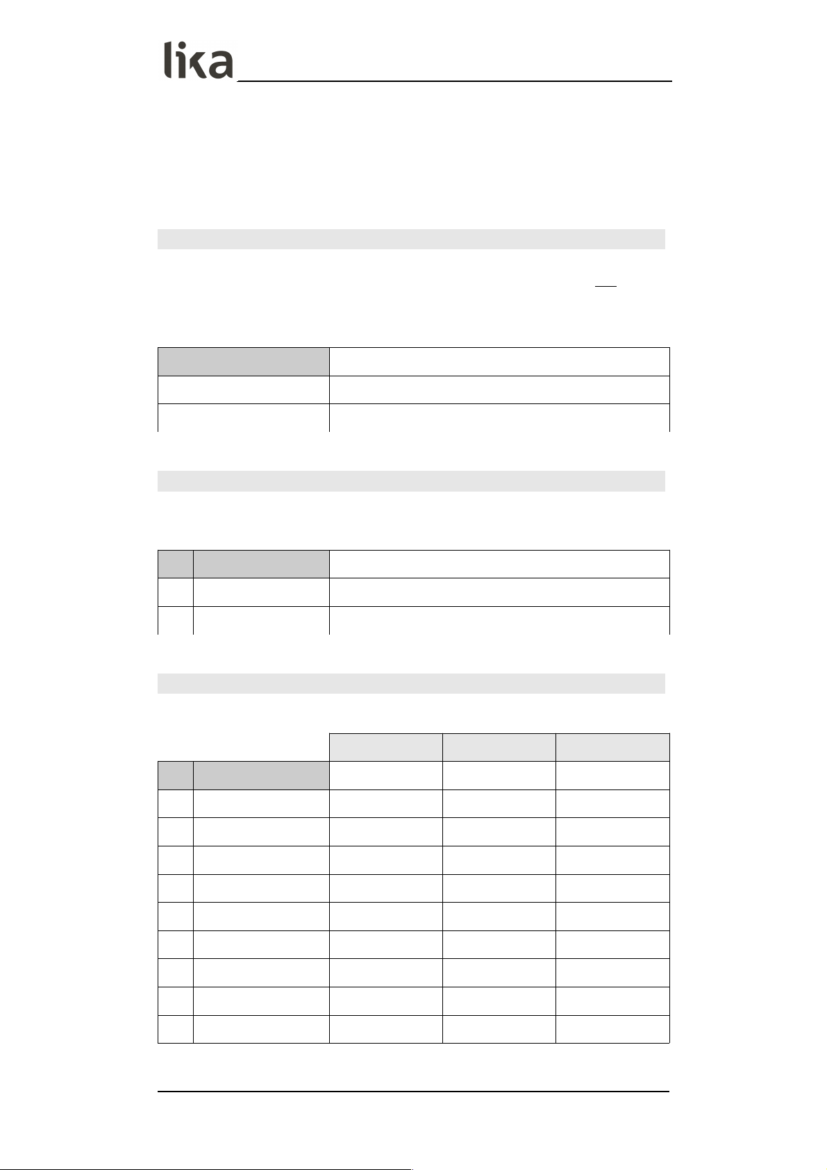
LD350 • LD355
6.13 Serial menu
The Serial menu allows to configure the basic settings of the serial interface
(terminal blocks 16, 17 and 18). For complete information on the serial port
features, please refer to the “4.8 Serial interface (AVI and DO order codes)”
section on page 23.
This function is only available for devices with order codes AVI and DO.
Unit number
This parameter allows to set the address of the serial device. You can assign to
the unit any address number between 11 and 99. The address must not contain
any “0“ because such numbers (20, 30, …) are reserved for collective addressing
(broadcast address).
11
Smallest address value
…
99
Highest address value
Serial baud rate
This parameter allows to set the serial transmission speed (baud rate).
Available options are:
0 9600
9600 baud
1 19200
19200 baud
2 38400
38400 baud
Serial format
This parameter allows to set the bit data format.
Data Bits Parity Bit Stop Bits
0 7-EVEN-1
7 even 1
1 7-EVEN-2
7 even 2
2 7-ODD-1
7 odd 1
3 7-ODD-2
7 odd 2
4 7-NONE-1
7 no 1
5 7-NONE-2
7 no 2
6 8-EVEN-1
8 even 1
7 8-ODD-1
8 odd 1
8 8-NONE-1
8 no 1
9 8-NONE-2
8 no 2
MAN LD350_LD355 E 1.0.odt 6 – Menus and parameters 61 of 84
Page 62

LD350 • LD355
Serial init
This parameter allows to set the baud rate for the transmission of the
initialization values to the OS6.0 software tool. If you set transmission values
higher than 9600 baud, the duration of the initialization procedure will be
shortened.
0 NO
The initialization values will be transmitted at 9600
baud. After initialization the unit will operate
according to the user settings again.
1 YES
The initialization values will be transmitted
according to the user defined baud rate (Serial
baud rate parameter). After initialization the unit
will go on operating according to the user settings
again.
Serial protocol
It sets the sequence of characters to be sent when using the serial output for
cyclic data transmission under time control (see the Serial timer (s) parameter).
If you set the option “1“ the unit address is removed from the string, this results
in a slightly faster transmission cycle.
The transmission string will be as follows:
Option 0
UN UN + / - X X X X X X X LF CR
Option 1
+ / - X X X X X X X LF CR
Where:
UN UN = serial address, e.g. “1 1”. See the Unit number parameter in
the previous page (option 0 only)
+ / - = plus / minus signs, i.e. positive / negative sign of transmitted
value
X X X X X X X X = data to be transmitted according to the setting in the Serial
value parameter
LF = line feed character
CR = carriage return character
0
Transmission string with serial address
1
Transmission string without serial address
MAN LD350_LD355 E 1.0.odt 6 – Menus and parameters 62 of 84
Page 63

LD350 • LD355
Serial timer (s)
This parameter sets the cycle time for the cyclic transmission of data set in the
Serial value parameter when using the serial output. The value is expressed in
seconds. In case of a serial request, the cyclic transmission is stopped for 20 s.
00.000
Cyclic transmission is switched off. The unit will
send data following a serial request or a “7 – Serial
print” command (see the Input 1 action, Input 2
action and Input 3 action parameters on pages 66
and 68).
…
60.000
Cycle time expressed in seconds.
Serial value
This parameter sets the value to be transmitted.
0
0 Measurement_Result
1
1 Speed_Value
2
2 Time_Result
3
3 Counter
4
4 Velocity_Speed
5
5 Batch_Counter
6
6 Minimal_Value
7
7 Maximal_Value
8
8 N.A.
9
9 N.A.
N.A. = not available
MAN LD350_LD355 E 1.0.odt 6 – Menus and parameters 63 of 84
Page 64

LD350 • LD355
6.14 Analog menu
The Analog menu allows to configure the basic settings of the analogue output
(terminal blocks 13 and 14 / 15).
For complete information on the analogue output features, please refer to the
“4.7 Analogue output (AVI order code)” section on page 22.
This function is only available for devices with order code AVI.
Analog format
This parameter sets the characteristics of the analogue output. The analogue
output is proportional to the display value.
If Analog format is set to “0 = -10…10V”, when the Counter operation mode
is active (see the “6.6 Counter operation mode menu” section on page 45) the
polarity of the analogue output depends on the polarity of the display value.
0 -10…10V
-10 … +10 V
1 0…20MA
0 … 20 mA
2 4…20MA
4 … 20 mA
Analog start
This parameter sets the start value of the analogue conversion. The start value
corresponds to the display value for an analogue output of 0 V or 0 mA or 4 mA
depending on the set Analog format.
-99999999
Smallest start value
+0000000.0
Default value
+99999999
Highest start value
Analog end
This parameter sets the end value of the analogue conversion. The end value
corresponds to the display value for an analogue output of (+/-)10 V or 20 mA
depending on the set Analog format.
-99999999
Smallest start value
+0001000.0
Default value
+99999999
Highest start value
MAN LD350_LD355 E 1.0.odt 6 – Menus and parameters 64 of 84
Page 65

LD350 • LD355
Analog gain (%)
This parameter sets the maximum conversion of the analogue output expressed
in percentage (%).
000.00
Smallest gain
100.00
Default value
110.00
Highest gain
EXAMPLE
If you set “102.00” next to this item the result will be a conversion of 10.2 V or
20.4 mA when the value set next to the Analog end parameter is reached.
If you set “95.00” next to this item the result will be a conversion of 9.5 V or 18
mA when the value set next to the Analog end parameter is reached.
Analog offset
This parameter sets the zero offset of the analogue output.
-99.99
Smallest offset
+00.00
Default value
+99.99
Highest offset
EXAMPLE
If you set “+00.20” next to this item the result will be an offset of 0.02 V or 0.04
mA as regards the Analog start value.
MAN LD350_LD355 E 1.0.odt 6 – Menus and parameters 65 of 84
Page 66

LD350 • LD355
6.15 Command menu
The Command menu allows to configure the operation of the inputs “10 - Ctrl.
In 1”, “11 - Ctrl. In 2” and “12 - Ctrl. In 3”.
For complete information on the control inputs features, please refer to the “4.6
Control inputs” section on page 21.
Input 1 action
This parameter sets the function of the input “10 - Ctrl. In 1”.
0 NO
No function
1 RESET/SET VALUE When the Timer operation mode is
active (see the “6.5 Timer operation
mode menu” section on page 43): it
resets the value to 0.
When the Counter operation mode is
active (see the “6.6 Counter operation
mode menu” section on page 45): it
resets / sets the value to the one set
next to the Set value parameter (see
on page 46).
When the Velocity operation mode is
active (see the “6.7 Velocity operation
mode menu” section on page 48): it
resets the value to 0.
(d) (s)
2 FREEZE
It freezes the current display value. (s)
3 KEY LOCK
It disables the touch screen. (s)
4 LOCK RELEASE
It releases the lock in all outputs / relay. (d)
5 RESET MIN/MAX
It resets the minimum / maximum
values.
(d) (s)
6 SERIAL PRINT
It allows serial data to be transmitted,
see the Serial value parameter on
page 63.
(d)
7 TEACH PRESEL. 1
The current display value is stored as
Preselection 1 (see the Preselection 1
parameter on page 50).
(d)
8 TEACH PRESEL. 2
The current display value is stored as
Preselection 2 (see the Preselection 2
parameter on page 50).
(d)
9 TEACH PRESEL. 3
The current display value is stored as
Preselection 3 (see the Preselection 3
parameter on page 50).
(d)
10 TEACH PRESEL. 4
The current display value is stored as
Preselection 4 (see the Preselection 4
parameter on page 50).
(d)
11 SCROLL DISPLAY
It scrolls through the available display (d)
MAN LD350_LD355 E 1.0.odt 6 – Menus and parameters 66 of 84
Page 67

LD350 • LD355
screens (see the “5.2 Screen structure
during operation” section on page 27).
12 CLEAR LOOP TIME
It clears all latched switching
conditions.
13 START PRESELECT
N.A.
14 ACTIVATE DATA
N.A.
15 STORE DATA
N.A.
16 TESTPROGRAM
N.A.
17 SET RED COLOR
The display lights up red. The colour
can be changed by setting an eventdependent switching condition (see the
parameters Event color 1, Event color
2, Event color 3 and Event color 4 in
the “6.9 Preselection 1 menu“ … “6.12
Preselection 4 menu“ on page 51 ff).
(d)
18 SET GREEN COLOR
The display lights up green. The colour
can be changed by setting an eventdependent switching condition (see the
parameters Event color 1, Event color
2, Event color 3 and Event color 4 in
the “6.9 Preselection 1 menu“ … “6.12
Preselection 4 menu“ on page 51 ff).
(d)
19 SET YELLOW COLOR
The display lights up yellow. The colour
can be changed by setting an eventdependent switching condition (see the
parameters Event color 1, Event color
2, Event color 3 and Event color 4 in
the “6.9 Preselection 1 menu“ … “6.12
Preselection 4 menu“ on page 51 ff).
(d)
20 INCREMENT BATCH
It increases the batch counter (see the
Counter operation mode, “6.6 Counter
operation mode menu” section on page
45).
(d)
21 DECREMENT BATCH
It decreases the batch counter (see the
Counter operation mode, “6.6 Counter
operation mode menu” section on page
45).
(d)
22 RESET/SET BATCH
It resets the batch counter (see the
Counter operation mode, “6.6 Counter
operation mode menu” section on page
45).
(d)
(s) = static switching (level evaluation)
Input 1 config. parameter must be set to be active at LOW / HIGH level
(see options 0 – ACTIVE LOW and 1 – ACTIVE HIGH).
MAN LD350_LD355 E 1.0.odt 6 – Menus and parameters 67 of 84
Page 68

LD350 • LD355
(d) = dynamic switching (edge evaluation)
Input 1 config. parameter must be set to activate at rising / falling
edge (see options 2 – RISING EDGE and 3 - FALLING EDGE).
N.A. = not available
Input 1 config.
This parameter sets the switching characteristics of the input “10 - Ctrl. In 1”.
0 ACTIVE LOW
It is active at “LOW“ level (static)
1 ACTIVE HIGH
It is active at “HIGH“ level (static)
2 RISING EDGE
It activates at rising edge
3 FALLING EDGE
It activates at falling edge
Input 2 action
This parameter sets the function of the input “11 - Ctrl. In 2”. For complete
information please refer to the Input 1 action parameter on page 66.
Input 2 config.
This parameter sets the switching characteristics of the input “11 - Ctrl. In 2”.
For complete information please refer to the Input 1 config. parameter on
page 68.
Input 3 action
This parameter sets the function of the input “12 - Ctrl. In 3”. For complete
information please refer to the Input 1 action parameter on page 66.
Input 3 config.
This parameter sets the switching characteristics of the input “12 - Ctrl. In 3”.
For complete information please refer to the Input 1 config. parameter on
page 68.
MAN LD350_LD355 E 1.0.odt 6 – Menus and parameters 68 of 84
Page 69

LD350 • LD355
6.16 Display menu
The Display menu allows to set the features of the display.
Parameter changes become active only after exiting the menu selection.
Color
This parameter sets the colour of the display.
It is also possible to enable an event-depending change of the colour of the
display by setting a switching condition (see the parameters Event color 1,
Event color 2, Event color 3 and Event color 4 in the “6.9 Preselection 1
menu“ … “6.12 Preselection 4 menu“ on page 51 ff).
Event-depending changes are only available for devices with order codes AVI,
DO and RO.
0 RED
The display is coloured in red
1 GREEN
The display is coloured in green
2 YELLOW
The display is coloured in yellow
Brightness (%)
This parameter sets the brightness of the display in percent (%).
010
Min. brightness
090
Default value
100
Max. brightness
Contrast
This parameter sets the viewing angle.
0
Viewing angle from top
1
Viewing angle from centre
2
Viewing angle from bottom
Screen saver (s)
This parameter sets the time expressed in seconds before the display is switched
off, starting from the last touch action.
A new touch action will activate the display again.
0000
Screen saver not active
…
9999
Longest time before the screen saver is activated
MAN LD350_LD355 E 1.0.odt 6 – Menus and parameters 69 of 84
Page 70

LD350 • LD355
Up-date time (s)
This parameter sets the update time of the display (refresh of the display), the
value is expressed in seconds. It does not affect the parameter values.
0.005
Shortest update time
0.100
Default value
9.999
Longest update time
Font
This parameter sets the font style.
0
Standard
1
Font 1
MAN LD350_LD355 E 1.0.odt 6 – Menus and parameters 70 of 84
Page 71

LD350 • LD355
6.17 Linearization menu
The linearisation function is configured in this menu. The linearisation points are
available only when the Speed, Process Time or Counter operation modes are
enabled (see on pages 37, 40 and 45 respectively). Furthermore this menu is
displayed only if the Linearization mode parameter in the General menu (see
on page 35) is set to either “1 – 1 QUADRANT” or “2 – 4 QUADRANT”; if 0 – OFF
option is set the Linearization menu does not appear.
For a complete description of the linearisation function and some examples
refer to the “6.17.1 Description of the linearisation function” section below.
P1(X)
…
P24(X)
X-coordinate of the linearisation point.
This value represents the display value the unit shows on the display without
linearisation.
-99999999
Smallest X-coordinate
+0000000.0
Default value
+99999999
Largest X-coordinate
P1(Y)
…
P24(Y)
Y-coordinate of the linearisation point.
This is the display value the unit will show on the display after linearisation.
EXAMPLE
P2(X) parameter value will be replaced by P2(Y) parameter value.
-99999999
Smallest Y-coordinate
+0000000.0
Default value
+99999999
Largest Y-coordinate
6.17.1 Description of the linearisation function
The linearisation function allows to convert a linear input signal into a nonlinear representation (or vice versa). 24 programmable X / Y coordinates
(interpolation points) are available, they can be freely arranged over the whole
conversion range at any desired distance. The unit uses linear interpolation
between two coordinates. Therefore it is advisable to set several coordinates
MAN LD350_LD355 E 1.0.odt 6 – Menus and parameters 71 of 84
Page 72

LD350 • LD355
where the curvature is greater and only few coordinates where the curvature is
lesser.
If you need to set an individual linearisation curve, the Linearization mode
parameter in the General menu (see on page 35) must be set to either “1 - 1
QUADRANT” or “2 - 4 QUADRANT” (see the diagrams below).
The parameters P1(X) to P24(X) are used to specify the coordinates on the xaxis. These are the measuring values that the unit would normally generate
according to the actual input signal.
Parameters P1(Y) to P24(Y) are the values that the unit will generate instead of
the X values, i.e. for instance P5(Y) replaces P5(X) etc.
The X coordinates must use continuously increasing settings, i.e. P1(X)
must have the lowest setting while P24(X) must have the highest setting
(P1(X) < P2(X) < P3(X) … < P23(X) < P24(X)). If the measured value is
greater than the last defined X value, the corresponding Y value is
displayed.
If the Linearization mode parameter in the General menu is set to “1 – 1
QUADRANT”, P1(X) parameter must be set to zero. Linearisation is only defined
in the positive range and the negative range will be mirrored symmetrical with
respect to the central point.
If the Linearization mode parameter in the General menu is set to “2 – 4
QUADRANT”, P1(X) parameter can be set also to a negative value. If the
measured value is smaller than P1(X), P1(Y) is displayed.
EXAMPLE
The picture below shows a sluiceway where the gate is controlled by means of
an incremental encoder. We want to display the opening of the gate "d", the
existing encoder information is proportional to the angular information .φ
MAN LD350_LD355 E 1.0.odt 6 – Menus and parameters 72 of 84
Page 73

LD350 • LD355
In this case we need to convert a non-linear input signal (incremental encoder
signals φ) into a linear representation (opening of the gate “d”). In the x-axis we
must set the actual values detected by the encoder while in the y-axis we will
set the opening values of the gate.
MAN LD350_LD355 E 1.0.odt 6 – Menus and parameters 73 of 84
Page 74
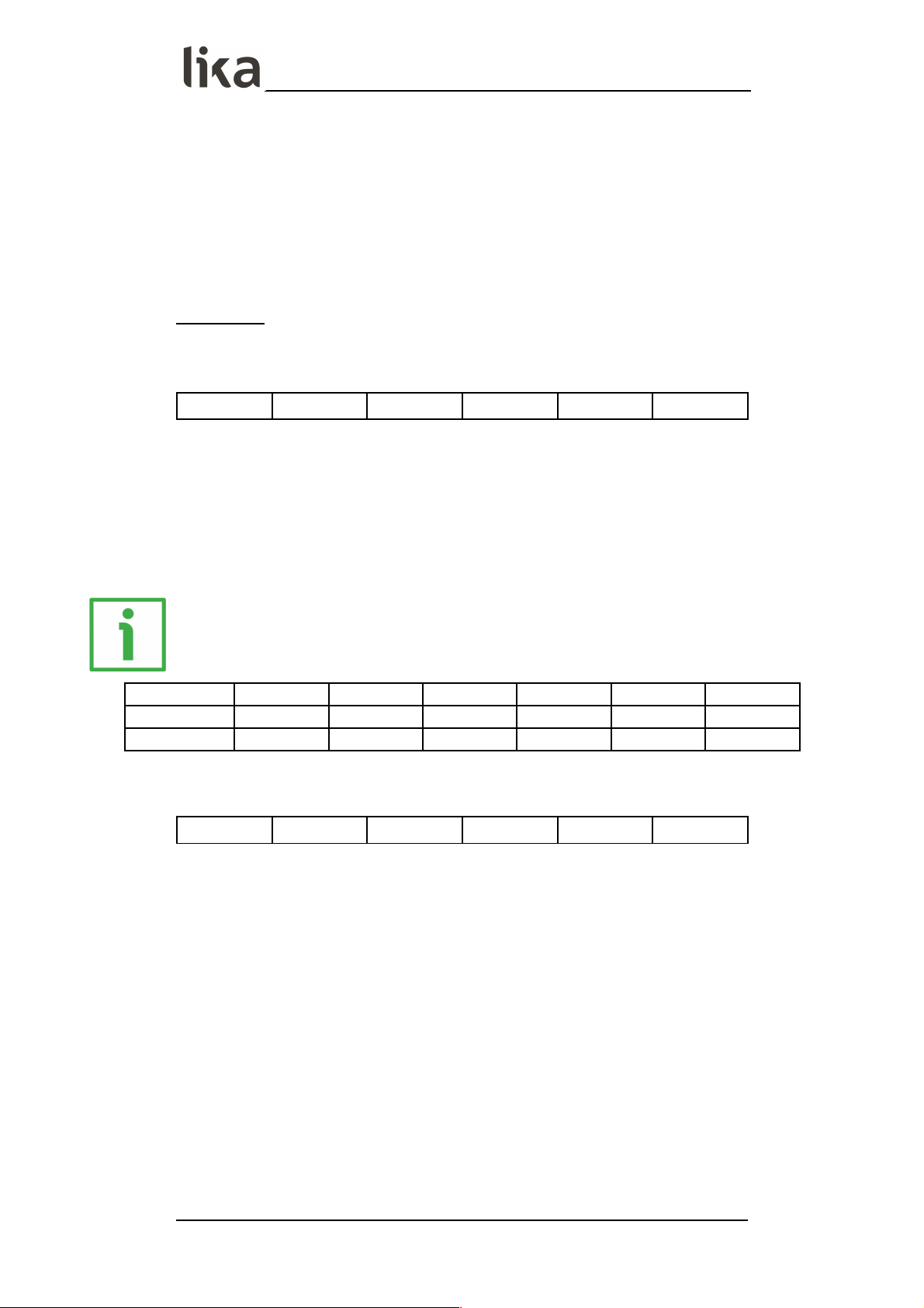
LD350 • LD355
7 - Appendix
7.1 Data readout via serial interface
All codes shown in the Serial value parameter (see the “6.13 Serial menu”
section on page 61) are available for serial readout by a PC or a PLC. For
communication the monitors use the Drivecom Protocol according to ISO 1745.
All protocol details can be found in the user's guide “MAN Serial Protocol
IFxx_LD25x_LD30x I_E.pdf”. It is available for download from our web page
www.lika.biz.
To request for a data transmission you must send the following request string to
the converter:
EOT AD1 AD2 C1 C2 ENQ
EOT = control character CTRL D (Hex 04)
AD1 = unit address, High Byte
AD2 = unit address, Low Byte
C1 = register code, High Byte
C2 = register code, Low Byte
ENQ = control character CTRL E (Hex 05)
EXAMPLE
The following example shows the request string for readout of the serial code =
1 from a unit having address “11”:
ASCII code: EOT 1 1 : 1 ENQ
Hex code: 04 31 31 3A 31 05
Binary code: 0000 0100 0011 0001 0011 0001 0011 1010 0011 0001 0000 0101
Following a correct request, the unit will respond:
STX C1 C2 xxxxx ETX BCC
STX = control character CTRL B (Hex 02)
C1 = register code, High Byte
C2 = register code, Low Byte
xxxxx= readout data
ETX = control character CTRL C (Hex 03)
BCC = block check character
MAN LD350_LD355 E 1.0.odt 7 - Appendix 74 of 84
Page 75
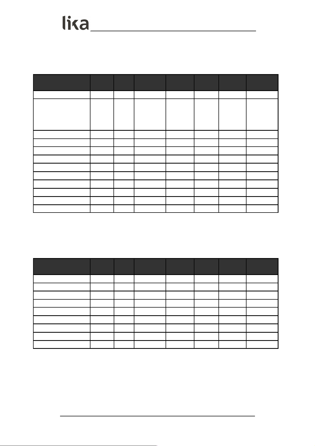
LD350 • LD355
8 - Parameters / serial codes
8.1 General menu
See the “6.2 General menu” section on page 33
Parameter
Serial
code
Value Min. value
Max.
value
Default
value
Positions Characters
Operational mode
0 3 0 4 0 1 0
Encoder properties
LD350
Encoder properties
LD355
1 0 0 3 0 1 0
Encoder supply
2 0 0 1 0 1 0
Counting direction
3 0 0 1 0 1 0
Scale units
4 29 0 29 0 2 0
Linearization mode
5 0 0 2 0 1 0
Pin preselection
6 0 0000 9999 0000 4 0
Pin parameter
7 0 0000 9999 0000 4 0
Back up memoryY
8 1 0 1 1 1 0
Factory settings
9 0 0 1 0 1 0
- 10 0 0 0 0 0 0
- 11 0 0 0 0 0 0
8.2 Speed operation mode menu
See the “6.3 Speed operation mode menu” section on page 37
Parameter
Serial
code
Value Min. value
Max.
value
Default
value
Positions Characters
Display value
12 1000 00000001 99999999 100.0 8 0
Base frequency (Hz)
13 100 000001 500000 100 6 0
Decimal point
14 1 0 7 1 1 0
Sampling time (s)
15 100 0.005 9.999 0.100 4 3
Wait time (s)
16 100 0.01 99.99 01.00 4 2
Standstill time (s)
17 0 00.00 99.99 00.00 4 2
Average filter
18 0 0 8 0 1 0
For/Rev detection
19 0 0 1 0 1 0
- 20 0 0 0 0 0 0
MAN LD350_LD355 E 1.0.odt 8 - Parameters / serial codes 75 of 84
Page 76

LD350 • LD355
8.3 Process Time operation mode menu
See the “6.4 Process Time operation mode menu” section on page 40
Parameter
Serial
code
Value Min. value
Max.
value
Default
value
Positions Characters
Display format
21 0 0 4 0 1 0
Display value
22 1000 00000001 99999999 1000 8 0
Base frequency (Hz)
23 100 000001 500000 100 6 0
Sampling time (s)
24 100 0.005 9.999 0.100 4 3
Wait time (s)
25 100 00.01 99.99 01.00 4 2
Standstill time (s)
26 0 00.00 99.99 00.00 4 2
Average filter
27 0 0 8 0 1 0
- 28 0 0 0 0 0 0
- 29 0 0 0 0 0 0
8.4 Timer operation mode menu
See the “6.5 Timer operation mode menu” section on page 43
Parameter
Serial
code
Value Min. value
Max.
value
Default
value
Positions Characters
Time base
30 7 0 7 0 1 0
Start / Stop
31 2 0 3 2 1 0
Auto set / reset
32 0 0 1 0 1 0
Latch function
33 0 0 1 0 1 0
Set value
34 0 00000.000 99999999 0 8 0
Inc / Dec mode
35 0 0 1 0 1 0
8.5 Counter operation mode menu
See the “6.6 Counter operation mode menu” section on page 45
Parameter
Serial
code
Value Min. value
Max.
value
Default
value
Positions Characters
Count mode
36 3 0 5 3 1 0
Factor
37 1000 00.00001 99.99999 1.00000 7 5
Set value
38 0 -99999999 99999999 +0 +/- 8 0
Decimal point
39 0 0 7 0 1 0
Batch mode
40 1 0 3 0 1 0
Batch set value
41 0 00000000 99999999 0 8 0
- 42 0 0 0 0 1 0
MAN LD350_LD355 E 1.0.odt 8 - Parameters / serial codes 76 of 84
Page 77
LD350 • LD355
8.6 Velocity operation mode menu
See the “6.7 Velocity operation mode menu” section on page 48
Parameter
Serial
code
Value Min. value
Max.
value
Default
value
Positions Characters
Start / Stop
A0 0 0 3 0 1 0
Display value
A1 1000 00000001 99999999 1000 8 0
Base time (s)
A2 1000 000.001 999.999 1.000 6 3
Decimal point
A3 0 0 7 0 1 0
Wait time (s)
A4 0 00.00 99.99 0 4 2
Standstill time (s)
A5 0 00.00 99.99 0 4 2
- A6 0 0 0 0 0 0
- A7 0 0 0 0 0 0
8.7 Preselection values menu
See the “6.8 Preselection values menu” section on page 50
Parameter
Serial
code
Value Min. value
Max.
value
Default
value
Positions Characters
Preselection 1
A8 1000 -9999999.9 9999999.9 100.0 +/- 8 0
Preselection 2
A9 2000 -9999999.9 9999999.9 200.0 +/- 8 0
Preselection 3
B0 3000 -9999999.9 9999999.9 300.0 +/- 8 0
Preselection 4
B1 4000 -9999999.9 9999999.9 400.0 +/- 8 0
8.8 Preselection 1 menu
See the “6.9 Preselection 1 menu” section on page 51
Parameter
Serial
code
Value Min. value
Max.
value
Default
value
Positions Characters
Mode 1
B2 7 0 9 0 1 0
Hysteresis 1
B3 0 000.0 99999 0 5 0
Pulse time 1 (s)
B4 500 00.000 60.000 0 5 3
Output target 1
B5 1 0 6 1 1 0
Output polarity 1
B6 0 0 1 0 1 0
Output lock 1
B7 0 0 1 0 1 0
Start up delay 1 (s)
B8 0 00.000 60.000 0 5 3
Event color 1
B9 0 0 3 0 1 0
MAN LD350_LD355 E 1.0.odt 8 - Parameters / serial codes 77 of 84
Page 78
LD350 • LD355
8.9 Preselection 2 menu
See the “6.10 Preselection 2 menu” section on page 55
Parameter
Serial
code
Value Min. value
Max.
value
Default
value
Positions Characters
Mode 2
C0 0 0 9 0 1 0
Hysteresis 2
C1 0 000.0 99999 0 5 0
Pulse time 2 (s)
C2 0 00.000 60.000 0 5 3
Output target 2
C3 2 0 6 1 1 0
Output polarity 2
C4 0 0 1 0 1 0
Output lock 2
C5 0 0 1 0 1 0
Start up delay 2 (s)
C6 0 00.000 60.000 0 5 3
Event color 2
C7 0 0 3 0 1 0
8.10 Preselection 3 menu
See the “6.11 Preselection 3 menu” section on page 57
Parameter
Serial
code
Value Min. value
Max.
value
Default
value
Positions Characters
Mode 3
C8 0 0 9 0 1 0
Hysteresis 3
C9 0 000.0 99999 0 5 0
Pulse time 3 (s)
D0 0 00.000 60.000 0 5 3
Output target 3
D1 3 0 6 1 1 0
Output polarity 3
D2 0 0 1 0 1 0
Output lock 3
D3 0 0 1 0 1 0
Start up delay 3 (s)
D4 0 0 1 0 1 0
Event color 3
D5 0 0 3 0 1 0
8.11 Preselection 4 menu
See the “6.12 Preselection 4 menu” section on page 59
Parameter
Serial
code
Value Min. value
Max.
value
Default
value
Positions Characters
Mode 4
D6 0 0 9 0 1 0
Hysteresis 4
D7 0 000.0 99999 0 5 0
Pulse time 4 (s)
D8 0 00.000 60.000 0 5 3
Output target 4
D9 4 0 6 1 1 0
Output polarity 4
E0 0 0 1 0 1 0
Output lock 4
E1 0 0 1 0 1 0
Start up delay 4 (s)
E2 0 0 1 0 1 0
Event color 4
E3 0 0 3 0 1 0
MAN LD350_LD355 E 1.0.odt 8 - Parameters / serial codes 78 of 84
Page 79

LD350 • LD355
8.12 Serial menu
See the “6.13 Serial menu” section on page 61
Parameter
Serial
code
Value Min. value
Max.
value
Default
value
Positions Characters
Unit number
90 11 11 99 11 2 0
Serial baud rate
91 0 0 2 0 1 0
Serial format
92 0 0 9 0 1 0
Serial init
9~ 0 0 1 0 1 0
Serial protocol
E4 0 0 1 0 1 0
Serial timer (s)
E5 0 00.000 60.000 0 5 3
Serial value
E6 0 0 9 0 1 0
- E7 0 0 0 0 0 0
8.13 Analog menu
See the “6.14 Analog menu” section on page 64
Parameter
Serial
code
Value Min. value
Max.
value
Default
value
Positions Characters
Analog format
E8 0 0 2 0 1 0
Analog start
E9 0 -99999999 99999999 0.0 +/- 8 0
Analog end
F0 10000 -99999999 99999999 1000.0 +/- 8 0
Analog gain (%)
F1 10000 000.00 110.00 100.00 5 2
Analog offset
F2 0 -99.99 99.99 0.00 84 2
- F3 0 0 0 0 0 0
- F4 0 0 0 0 0 0
8.14 Command menu
See the “6.15 Command menu” section on page 66
Parameter
Serial
code
Value Min. value
Max.
value
Default
value
Positions Characters
Input 1 action
F5 20 0 22 0 2 0
Input 1 config.
F6 2 0 3 2 1 0
Input 2 action
F7 21 0 22 0 2 0
Input 2 config.
F8 2 0 3 2 1 0
Input 3 action
F9 22 0 22 0 2 0
Input 3 config.
G0 2 0 3 2 1 0
- G1 0 0 0 0 1 0
- G2 0 0 0 0 1 0
- G3 0 0 0 0 1 0
- G4 0 0 0 0 1 0
- G5 0 0 0 0 1 0
MAN LD350_LD355 E 1.0.odt 8 - Parameters / serial codes 79 of 84
Page 80

LD350 • LD355
8.15 Display menu
See the “6.16 Display menu” section on page 69
Parameter
Serial
code
Value Min. value
Max.
value
Default
value
Positions Characters
Color
G6 0 0 2 0 1 0
Brightness (%)
G7 90 010 100 090 3 0
Contrast
G8 1 0 2 1 1 0
Screen saver (s)
G9 0 0000 9999 0 4 0
Up-date time (s)
H0 100 0.005 9.999 0.100 4 3
Font
H1 0 0 1 0 1 0
- H2 0 0 0 0 1 0
- H3 0 0 0 0 1 0
- H4 0 0 0 0 1 0
8.16 Linearization menu
See the “6.17 Linearization menu” section on page 71
Parameter
Serial
code
Value Min. value
Max.
value
Default
value
Positions Characters
P1(X)
H5 0 -99999999 99999999 0.0 +/- 8 0
P1(Y)
H6 0 -99999999 99999999 0.0 +/- 8 0
P2(X)
H7 0 -99999999 99999999 0.0 +/- 8 0
P2(Y)
H8 0 -99999999 99999999 0.0 +/- 8 0
P3(X)
H9 0 -99999999 99999999 0.0 +/- 8 0
P3(Y)
I0 0 -99999999 99999999 0.0 +/- 8 0
P4(X)
I1 0 -99999999 99999999 0.0 +/- 8 0
P4(Y)
I2 0 -99999999 99999999 0.0 +/- 8 0
P5(X)
I3 0 -99999999 99999999 0.0 +/- 8 0
P5(Y)
I4 0 -99999999 99999999 0.0 +/- 8 0
P6(X)
I5 0 -99999999 99999999 0.0 +/- 8 0
P6(Y)
I6 0 -99999999 99999999 0.0 +/- 8 0
P7(X)
I7 0 -99999999 99999999 0.0 +/- 8 0
P7(Y)
I8 0 -99999999 99999999 0.0 +/- 8 0
P8(X)
I9 0 -99999999 99999999 0.0 +/- 8 0
P8(Y)
J0 0 -99999999 99999999 0.0 +/- 8 0
P9(X)
J1 0 -99999999 99999999 0.0 +/- 8 0
P9(Y)
J2 0 -99999999 99999999 0.0 +/- 8 0
P10(X)
J3 0 -99999999 99999999 0.0 +/- 8 0
P10(Y)
J4 0 -99999999 99999999 0.0 +/- 8 0
P11(X)
J5 0 -99999999 99999999 0.0 +/- 8 0
P11(Y)
J6 0 -99999999 99999999 0.0 +/- 8 0
(continue on next page)
MAN LD350_LD355 E 1.0.odt 8 - Parameters / serial codes 80 of 84
Page 81

LD350 • LD355
(continued)
Parameter
Serial
code
Value Min. value
Max.
value
Default
value
Positions Characters
P12(X)
J7 0 -99999999 99999999 0.0 +/- 8 0
P12(Y)
J8 0 -99999999 99999999 0.0 +/- 8 0
P13(X)
J9 0 -99999999 99999999 0.0 +/- 8 0
P13(Y)
K0 0 -99999999 99999999 0.0 +/- 8 0
P14(X)
K1 0 -99999999 99999999 0.0 +/- 8 0
P14(Y)
K2 0 -99999999 99999999 0.0 +/- 8 0
P15(X)
K3 0 -99999999 99999999 0.0 +/- 8 0
P15(Y)
K4 0 -99999999 99999999 0.0 +/- 8 0
P16(X)
K5 0 -99999999 99999999 0.0 +/- 8 0
P16(Y)
K6 0 -99999999 99999999 0.0 +/- 8 0
P17(X)
K7 0 -99999999 99999999 0.0 +/- 8 0
P17(Y)
K8 0 -99999999 99999999 0.0 +/- 8 0
P18(X)
K9 0 -99999999 99999999 0.0 +/- 8 0
P18(Y)
L0 0 -99999999 99999999 0.0 +/- 8 0
P19(X)
L1 0 -99999999 99999999 0.0 +/- 8 0
P19(Y)
L2 0 -99999999 99999999 0.0 +/- 8 0
P20(X)
L3 0 -99999999 99999999 0.0 +/- 8 0
P20(Y)
L4 0 -99999999 99999999 0.0 +/- 8 0
P21(X)
L5 0 -99999999 99999999 0.0 +/- 8 0
P21(Y)
L6 0 -99999999 99999999 0.0 +/- 8 0
P22(X)
L7 0 -99999999 99999999 0.0 +/- 8 0
P22(Y)
L8 0 -99999999 99999999 0.0 +/- 8 0
P23(X)
L9 0 -99999999 99999999 0.0 +/- 8 0
P23(Y)
M0 0 -99999999 99999999 0.0 +/- 8 0
P24(X)
M1 0 -99999999 99999999 0.0 +/- 8 0
P24(Y)
M2 0 -99999999 99999999 0.0 +/- 8 0
MAN LD350_LD355 E 1.0.odt 8 - Parameters / serial codes 81 of 84
Page 82

LD350 • LD355
8.17 Serial codes of commands
Serial code Command
54 RESET/SET
55 FREEZE DISPLAY
56 TOUCH DISABLE
57 CLR LOCK
58 CLR MIN MAX
59 SERIAL PRINT
60 TEACH PRES 1
61 TEACH PRES 2
62 TEACH PRES 3
63 TEACH PRES 4
64 SCROLL_DISPLAY
65 CLEAR LOOP TIME
66 START PRESELECTION
67 ACTIVATE DATA
68 STORE EEPROM
69 TESTPROGRAM
MAN LD350_LD355 E 1.0.odt 8 - Parameters / serial codes 82 of 84
Page 83

This page intentionally left blank
Page 84

Document release Release date Description
1.0 27.09.2018 First issue
Lika Electronic
Via S. Lorenzo, 25 • 36010 Carrè (VI) • Italy
Tel. +39 0445 806600
Fax +39 0445 806699
info@lika.biz • www.lika.biz
 Loading...