

Page 1
User's guide
LD200
• Position display, counter, event transmitter, converter
• For HTL/Push-Pull, TTL/Line Driver, Sine/Cosine 1Vpp incremental
encoders/sensors and SSI absolute encoders/sensors
• Linear (mm, inches,...) and angular (degrees) display function
• 1 input and 3 dedicated digital outputs
• RS-232 interface and software tool for easy configuration
Suitable for the following models:
• LD200 universal display
General Contents
Preliminary information 10
1 - Safety summary 11
2 - Identification 13
3 - Mounting instructions 14
4 - Electrical connections 16
5 - Functions 19
6 - Setup 25
7 - RS-232 serial interface 53
8 - Application software for PC 65
Lika Electronic • Tel. +39 0445 806600 • info@lika.biz • www.lika.biz
Smart encoders & actuators
Page 2

This publication was produced by Lika Electronic s.r.l. 2018. All rights reserved. Tutti i diritti riservati. Alle Rechte vorbehalten. Todos los
derechos reservados. Tous droits réservés.
This document and information contained herein are the property of Lika Electronic s.r.l. and shall not be reproduced in whole or in
part without prior written approval of Lika Electronic s.r.l. Translation, reproduction and total or partial modification (photostat copies,
film and microfilm included and any other means) are forbidden without written authorisation of Lika Electronic s.r.l.
The information herein is subject to change without notice and should not be construed as a commitment by Lika Electronic s.r.l. Lika
Electronic s.r.l. reserves the right to make all modifications at any moments and without forewarning.
This manual is periodically reviewed and revised. As required we suggest checking if a new or updated edition of this document is
available at Lika Electronic s.r.l.'s website. Lika Electronic s.r.l. assumes no responsibility for any errors or omissions in this document.
Critical evaluation of this manual by the user is welcomed. Your comments assist us in preparation of future documentation, in order
to make it as clear and complete as possible. Please send an e-mail to the following address info@lika.it for submitting your
comments, suggestions and criticisms.
Page 3

General contents
User's guide......................................................................................................................................................... 1
General contents.............................................................................................................................................................................3
Subject index.....................................................................................................................................................................................8
Typographic and iconographic conventions...................................................................................................................9
Preliminary information...........................................................................................................................................................10
1 - Safety summary....................................................................................................................................................................11
1.1 Safety........................................................................................................................................................................................11
1.2 Electrical safety....................................................................................................................................................................11
1.3 Mechanical safety...............................................................................................................................................................12
2 - Identification..........................................................................................................................................................................13
3 - Mounting instructions......................................................................................................................................................14
3.1 Overall dimensions..............................................................................................................................................................14
3.2 Installation.............................................................................................................................................................................15
3.3 Cleaning and maintenance.............................................................................................................................................15
4 - Electrical connections.......................................................................................................................................................16
4.1 CON6 connections (Power supply to the display).................................................................................................16
4.2 CON1 connections (Mini-DIN connector).................................................................................................................16
4.3 CON2 connections (RS-232 serial interface)...........................................................................................................16
4.4 CON3 connections (Sine/Cosine 1Vpp)......................................................................................................................17
4.5 CON5 connections (Push-Pull, Line Driver, SSI).....................................................................................................17
4.6 Jumper J1 (Power supply to the encoder / sensor)..............................................................................................18
4.7 CON4 connections (Outputs and Input)....................................................................................................................18
5 - Functions...................................................................................................................................................................................19
5.1 Start up....................................................................................................................................................................................19
5.2 Function of the LEDs..........................................................................................................................................................19
5.3 Function of the keys...........................................................................................................................................................20
5.4 Default parameters (factory settings)........................................................................................................................20
5.5 Absolute / relative counting mode..............................................................................................................................20
5.6 Memory on power down (for incremental and 1Vpp encoders / sensors).................................................21
5.7 Offset........................................................................................................................................................................................21
5.8 Displaying values in millimetres / degrees / inches / fractional inches.......................................................21
5.9 Zero setting (or Preset setting).....................................................................................................................................21
5.10 Preset Input function (CON4, pins 7 and 8)..........................................................................................................22
5.10.1 Examples of using the input...........................................................................................................................23
5.11 OUT 1, OUT 2, OUT 3 output function (CON4, pins 1 … 6)..............................................................................23
5.11.1 Examples of using the outputs......................................................................................................................24
6 - Setup...........................................................................................................................................................................................25
6.1 Access to setup menus......................................................................................................................................................25
6.2 Basic settings........................................................................................................................................................................26
Ad..................................................................................................................................................................................................26
L_int............................................................................................................................................................................................26
6.3 Parameter settings..............................................................................................................................................................26
d_tyPE........................................................................................................................................................................................26
6.4 AB0 incremental rotary encoder..................................................................................................................................27
PPr................................................................................................................................................................................................27
diSt_r..........................................................................................................................................................................................27
Page 4

MOd 360...................................................................................................................................................................................27
Unit..............................................................................................................................................................................................27
EnAbLE 0...................................................................................................................................................................................27
dir..................................................................................................................................................................................................28
dEciMALS..................................................................................................................................................................................28
PrESEt.........................................................................................................................................................................................28
LIMIt P.......................................................................................................................................................................................28
LIMIt N.......................................................................................................................................................................................28
OFFSEt........................................................................................................................................................................................29
EnAb. In.....................................................................................................................................................................................29
6.5 1Vpp Sine/Cosine rotary encoder.................................................................................................................................30
PPr................................................................................................................................................................................................30
diSt_r..........................................................................................................................................................................................30
MOd 360...................................................................................................................................................................................30
Unit..............................................................................................................................................................................................30
EnAbLE 0...................................................................................................................................................................................30
dir..................................................................................................................................................................................................31
dEciMALS..................................................................................................................................................................................31
PrESEt.........................................................................................................................................................................................31
LIMIt P.......................................................................................................................................................................................31
LIMIt N.......................................................................................................................................................................................31
OFFSEt........................................................................................................................................................................................32
EnAb. In.....................................................................................................................................................................................32
6.6 Absolute rotary encoder with SSI interface.............................................................................................................33
ForMAt.......................................................................................................................................................................................33
PPr................................................................................................................................................................................................33
n_turnS......................................................................................................................................................................................33
diSt_r..........................................................................................................................................................................................33
Prtcl.............................................................................................................................................................................................34
codE.............................................................................................................................................................................................34
Unit..............................................................................................................................................................................................34
dir..................................................................................................................................................................................................34
dEciMALS..................................................................................................................................................................................34
PrESEt.........................................................................................................................................................................................35
LIMIt P.......................................................................................................................................................................................35
LIMIt N.......................................................................................................................................................................................35
OFFSEt........................................................................................................................................................................................35
EnAb. In.....................................................................................................................................................................................36
6.6.1 Connecting an SSI encoder with “MSB Left Aligned” protocol..........................................................36
6.7 Lika's SM2, SM25, SM5 magnetic sensors................................................................................................................40
Pitch............................................................................................................................................................................................40
rES................................................................................................................................................................................................40
Unit..............................................................................................................................................................................................40
dir..................................................................................................................................................................................................40
PrESEt.........................................................................................................................................................................................40
LIMIt P.......................................................................................................................................................................................41
LIMIt N.......................................................................................................................................................................................41
OFFSEt........................................................................................................................................................................................41
EnAb. In.....................................................................................................................................................................................41
Page 5

6.8 AB0 incremental linear encoder/sensor....................................................................................................................43
rES................................................................................................................................................................................................43
Unit..............................................................................................................................................................................................43
EnAbLE 0...................................................................................................................................................................................43
dir..................................................................................................................................................................................................43
PrESEt.........................................................................................................................................................................................44
LIMIt P.......................................................................................................................................................................................44
LIMIt N.......................................................................................................................................................................................44
OFFSEt........................................................................................................................................................................................44
EnAb. In.....................................................................................................................................................................................44
6.9 1Vpp Sine/Cosine linear encoder/sensor...................................................................................................................46
Pitch............................................................................................................................................................................................46
rES................................................................................................................................................................................................46
Unit..............................................................................................................................................................................................46
EnAbLE 0...................................................................................................................................................................................46
dir..................................................................................................................................................................................................47
PrESEt.........................................................................................................................................................................................47
LIMIt P.......................................................................................................................................................................................47
LIMIt N.......................................................................................................................................................................................47
OFFSEt........................................................................................................................................................................................47
EnAb. In.....................................................................................................................................................................................48
6.10 Absolute linear encoder/sensor with SSI interface............................................................................................49
ForMAt.......................................................................................................................................................................................49
StEPS...........................................................................................................................................................................................49
rES................................................................................................................................................................................................50
codE.............................................................................................................................................................................................50
Unit..............................................................................................................................................................................................50
dir..................................................................................................................................................................................................50
PrESEt.........................................................................................................................................................................................50
LIMIt P.......................................................................................................................................................................................51
LIMIt N.......................................................................................................................................................................................51
OFFSEt........................................................................................................................................................................................51
EnAb. In.....................................................................................................................................................................................51
7 - RS-232 serial interface....................................................................................................................................................53
7.1 Connection to a PC.............................................................................................................................................................53
7.2 Setting the serial port.......................................................................................................................................................53
7.3 Communication protocol.................................................................................................................................................53
7.3.1 Protocol structure..................................................................................................................................................54
SOF......................................................................................................................................................................................54
ADD.....................................................................................................................................................................................54
CMD....................................................................................................................................................................................54
ACK.....................................................................................................................................................................................54
DATA..................................................................................................................................................................................54
CHK.....................................................................................................................................................................................55
EOF......................................................................................................................................................................................55
7.3.2 Commands.................................................................................................................................................................55
TPOS...................................................................................................................................................................................56
TDEV...................................................................................................................................................................................56
RDEV...................................................................................................................................................................................56
Page 6

TFOR...................................................................................................................................................................................57
RFOR...................................................................................................................................................................................57
TPPR....................................................................................................................................................................................57
RPPR...................................................................................................................................................................................57
TREV....................................................................................................................................................................................57
RREV...................................................................................................................................................................................57
TDST....................................................................................................................................................................................57
RDST...................................................................................................................................................................................57
T360...................................................................................................................................................................................57
R360...................................................................................................................................................................................57
TSTE....................................................................................................................................................................................57
RSTE....................................................................................................................................................................................57
TPIT.....................................................................................................................................................................................58
RPIT.....................................................................................................................................................................................58
TRES....................................................................................................................................................................................58
RRES...................................................................................................................................................................................58
TPRO...................................................................................................................................................................................58
RPRO..................................................................................................................................................................................58
TCOD..................................................................................................................................................................................59
RCOD..................................................................................................................................................................................59
TUNI....................................................................................................................................................................................59
RUNI...................................................................................................................................................................................59
TETZ....................................................................................................................................................................................59
RETZ....................................................................................................................................................................................59
TDIR....................................................................................................................................................................................59
RDIR....................................................................................................................................................................................59
TDEC...................................................................................................................................................................................60
RDEC...................................................................................................................................................................................60
TREF....................................................................................................................................................................................60
RREF................................................................................................................................................................................... 60
TLIP.....................................................................................................................................................................................60
RLIP.....................................................................................................................................................................................60
TLIM....................................................................................................................................................................................60
RLIM...................................................................................................................................................................................60
TOFF....................................................................................................................................................................................60
ROFF...................................................................................................................................................................................60
TEIN....................................................................................................................................................................................60
REIN....................................................................................................................................................................................60
TADR...................................................................................................................................................................................61
RADR..................................................................................................................................................................................61
TRLA................................................................................................................................................................................... 61
RRLA...................................................................................................................................................................................61
TVER....................................................................................................................................................................................61
ZERO...................................................................................................................................................................................61
STAR...................................................................................................................................................................................62
STOP...................................................................................................................................................................................62
“Null”.................................................................................................................................................................................62
7.3.3 Examples of using the protocol and the commands..............................................................................63
Setting the Device type..........................................................................................................................................63
Page 7

Setting the Pulses per revolution......................................................................................................................63
Reading the position of the decimal separator...........................................................................................63
Reading the current position..............................................................................................................................63
Zero setting the position value..........................................................................................................................64
Starting the cyclic transmission.........................................................................................................................64
Reading the current position cyclically..........................................................................................................64
Stopping the cyclic transmission.......................................................................................................................64
8 - Application software for PC..........................................................................................................................................65
8.1 Serial communication settings......................................................................................................................................65
8.2 Selecting the encoder type.............................................................................................................................................66
8.3 Reading the encoder parameters.................................................................................................................................67
8.4 Setting the encoder parameters...................................................................................................................................67
8.5 Reading the position..........................................................................................................................................................68
8.6 Setting the absolute / relative counting mode......................................................................................................68
8.7 Reading the position cyclically......................................................................................................................................68
Page 8

Subject index
A
Ad............................................................................................26
C
codE................................................................................34, 50
D
d_tyPE...................................................................................26
dEciMALS..............................................................28, 31, 34
dir..............................................28, 31, 34, 40, 43, 47, 50
diSt_r......................................................................27, 30, 33
E
EnAb. In...................................29, 32, 36, 41, 44, 48, 51
EnAbLE 0.......................................................27, 30, 43, 46
F
ForMAt..........................................................................33, 49
L
L_int.......................................................................................26
LIMIt N.....................................28, 31, 35, 41, 44, 47, 51
LIMIt P.....................................28, 31, 35, 41, 44, 47, 51
M
MOd 360.......................................................................27, 30
N
n_turnS................................................................................33
O
OFFSEt......................................29, 32, 35, 41, 44, 47, 51
P
Pitch...............................................................................40, 46
PPr...........................................................................27, 30, 33
PrESEt......................................28, 31, 35, 40, 44, 47, 50
Prtcl........................................................................................34
R
rES....................................................................40, 43, 46, 50
S
StEPS.....................................................................................49
U
Unit...........................................27, 30, 34, 40, 43, 46, 50
Page 9
Typographic and iconographic conventions
In this guide, to make it easier to understand and read the text the following typographic and
iconographic conventions are used:
• parameters and objects both of the device and the interface are coloured in GREEN;
• alarms are coloured in RED;
• states are coloured in FUCSIA.
When scrolling through the text some icons can be found on the side of the page: they are expressly
designed to highlight the parts of the text which are of great interest and significance for the user.
Sometimes they are used to warn against dangers or potential sources of danger arising from the use of
the device. You are advised to follow strictly the instructions given in this guide in order to guarantee
the safety of the user and ensure the performance of the device. In this guide the following symbols are
used:
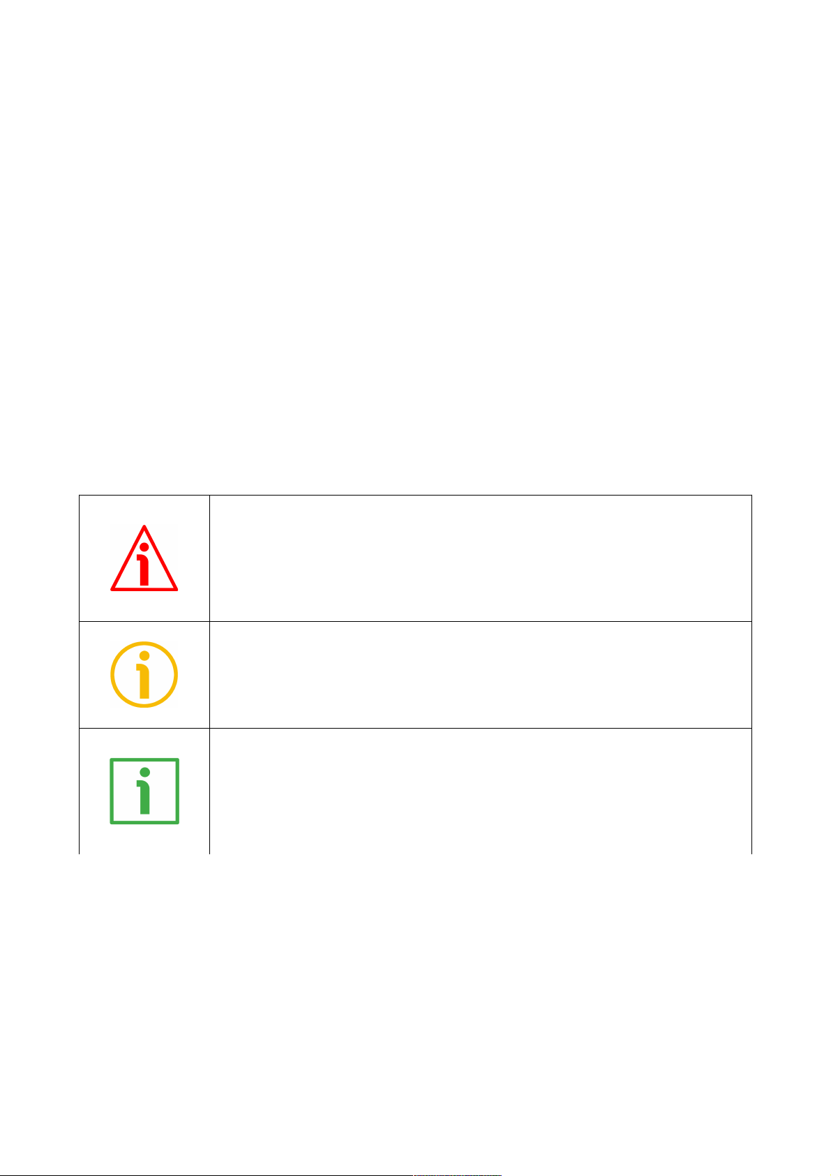
This icon, followed by the word WARNING, is meant to highlight the parts of the
text where information of great significance for the user can be found: user must
pay the greatest attention to them! Instructions must be followed strictly in order
to guarantee the safety of the user and a correct use of the device. Failure to heed
a warning or comply with instructions could lead to personal injury and/or damage
to the unit or other equipment.
This icon, followed by the word NOTE, is meant to highlight the parts of the text
where important notes needful for a correct and reliable use of the device can be
found. User must pay attention to them! Failure to comply with instructions could
cause the equipment to be set wrongly: hence a faulty and improper working of
the device could be the consequence.
This icon is meant to highlight the parts of the text where suggestions useful for
making it easier to set the device and optimize performance and reliability can be
found. Sometimes this symbol is followed by the word EXAMPLE when instructions
for setting parameters are accompanied by examples to clarify the explanation.
Page 10
Preliminary information
This guide is designed to provide the most complete information the operator needs to correctly and
safely install and operate the LD200 universal display.
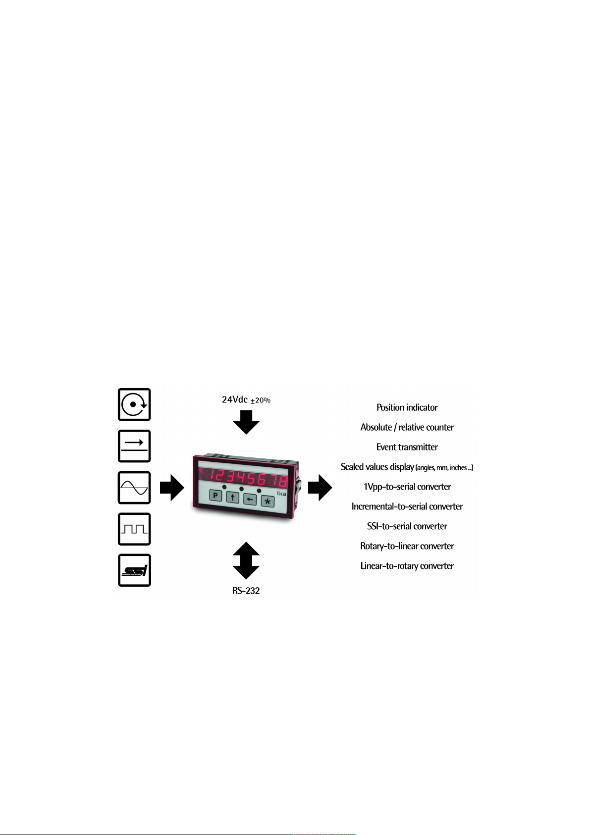
LD200 is a position display which allows to connect a variety of encoders / sensors, they can be
incremental (HTL/Push-Pull, TTL/Line Driver, Sine/Cosine 1Vpp) and absolute (SSI) as well as rotary and
linear.
User's interface is a scratch resistant polycarbonate keyboard fitted with 4 multifunction keys and a 7
segment 8 digit high brightness LED display. The device is also equipped with 3 status LEDs, 1 input and 3
digital outputs designed to operate dedicated functions.
The display provides an RS-232 interface for connection to a PC and configuration via free software tool.
Among the available functions:
• position indicators;
• absolute / relative counter;
• event transmitter.
It allows to display and scale both linear (millimeters, inches, fractional inches) and angular (degreses)
measurement values.
For technical specifications please refer to the product datasheet.
To make it easier to read the text, this guide can be divided into two main sections.
In the first section (from section 1 to section 4) general information concerning the safety, the
mechanical installation and the electrical connection.
In the second section (from section 5 to section 8) both general and specific information is given on the
operator's menu, the use of the keys, the setup procedure and the serial interface.
Page 11
LD200
1 - Safety summary
1.1 Safety
Always adhere to the professional safety and accident prevention
regulations applicable to your country during device installation and
operation;
installation and maintenance operations have to be carried out by qualified
personnel only, with power supply disconnected and stationary mechanical
parts;
device must be used only for the purpose appropriate to its design: use for
purposes other than those for which it has been designed could result in
serious personal and/or the environment damage;
high current, voltage and moving mechanical parts can cause serious or
fatal injury;
warning ! Do not use in explosive or flammable areas;
failure to comply with these precautions or with specific warnings
elsewhere in this manual violates safety standards of design, manufacture,
and intended use of the equipment;
Lika Electronic assumes no liability for the customer's failure to comply with
these requirements.
1.2 Electrical safety
Turn OFF power supply before connecting the device;
connect following to explanation in the ”4 - Electrical connections” section
on page 16;
in compliance with 2014/30/EU norm on electromagnetic
compatibility, the following precautions must be taken:
- before handling and installing the equipment, discharge
electrical charge from your body and tools which may come in
touch with the device;
- power supply must be stabilized without noise; install EMC filters on
device power supply if needed;
- always use shielded cables (twisted pair cables whenever possible);
- avoid cables runs longer than necessary;
- avoid running the signal cable near high voltage power cables;
- mount the device as far as possible from any capacitive or inductive
noise source; shield the device from noise source if needed;
- minimize noise by connecting the unit to ground (GND). Make sure
that ground (GND) is not affected by noise. The connection point to
ground can be situated both on the device side and on user’s side.
The best solution to minimize the interference must be carried out
by the user.
MAN LD200 E 2.3.odt 1 - Safety summary 11 of 72
Page 12

LD200
1.3 Mechanical safety
Install the device following strictly the information in the “3 - Mounting
instructions” section on page 14;
do not disassemble the unit;
do not tool the unit;
delicate electronic equipment: handle with care;
do not subject the device to knocks or shocks;
respect the environmental characteristics of the device.
MAN LD200 E 2.3.odt 1 - Safety summary 12 of 72
Page 13

LD200
2 - Identification
Device can be identified through the order code and the serial number printed
on the label applied to its body. Information is listed in the delivery document
too. Please always quote the order code and the serial number when reaching
Lika Electronic for purchasing spare parts or needing assistance. For any
information on the technical characteristics of the product, refer to the
technical catalogue.
Warning: devices having order code ending with “/Sxxx” may have
mechanical and electrical characteristics different from standard
and be supplied with additional documentation for special
connections (Technical info).
MAN LD200 E 2.3.odt 2 - Identification 13 of 72
Page 14
LD200
3 - Mounting instructions
WARNING
Installation and maintenance operations have to be carried out by qualified
personnel only, with power supply disconnected and mechanical parts
compulsorily in stop.
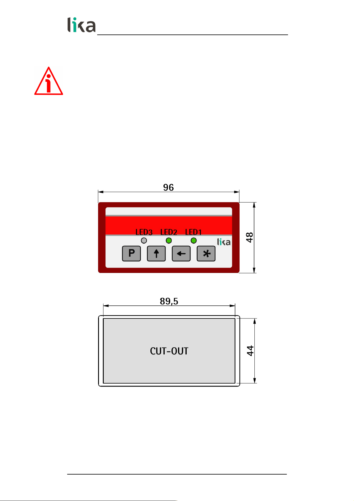
3.1 Overall dimensions
Insert the display without panel clips through the cut-out (approx. 89.5 W x 44
H mm / 3.523” W x 1.732” H) made in the panel.
Mount the panel clips on the sides of the display housing and tighten the
screws until fixed.
Values are expressed in millimeters
MAN LD200 E 2.3.odt 3 - Mounting instructions 14 of 72
Page 15

LD200
3.2 Installation
The device is allowed to be installed and operated only within the permissible
temperature range (0°C +70°C / +32°F +158°F). Please ensure an adequate
ventilation and avoid any direct contact between the device and gases / liquids.
Before installation or maintenance, the unit must be disconnected from all
voltage sources. Furthermore it must be ensured that no danger can arise in the
event of contact with the disconnected voltage sources.
All selected wires and insulations must comply with the provided voltage and
temperature ranges. Furthermore all country and application specific standards
which are relevant for structure, form and quality of the wires must be ensured.
Indications about the permissible wire cross sections for wiring are described in
the product datasheet.
Before starting the unit for the first time it must be ensured that all connections
and wires are firmly plugged in and secured to the screw terminal blocks. All
terminal blocks (including unused ones) must be fastened by turning the
relevant screws clockwise up to the end position.
For placement, wiring, environmental conditions as well as shielding and
earthing/grounding of the supply lines you must comply with the general
standards stated for industrial automation industry and the specific shielding
instructions provided by the manufacturer.
3.3 Cleaning and maintenance
To clean the unit please just use a slightly damp (not wet!), soft cloth. For the
rear side no cleaning is necessary. For an unscheduled, individual cleaning of the
rear side the maintenance technicians or installation operators are selfresponsible.
During normal operation no maintenance is necessary. In case of unexpected
problems, failures or malfunctions the device must be shipped back to the
manufacturer for any checking, adjustment or repair (if necessary).
Unauthorized opening and repair operations can have negative effects or cause
failures to the protection measures of the unit.
MAN LD200 E 2.3.odt 3 - Mounting instructions 15 of 72
Page 16
LD200
4 - Electrical connections
WARNING
Power supply must be turned off before performing any electrical connection!
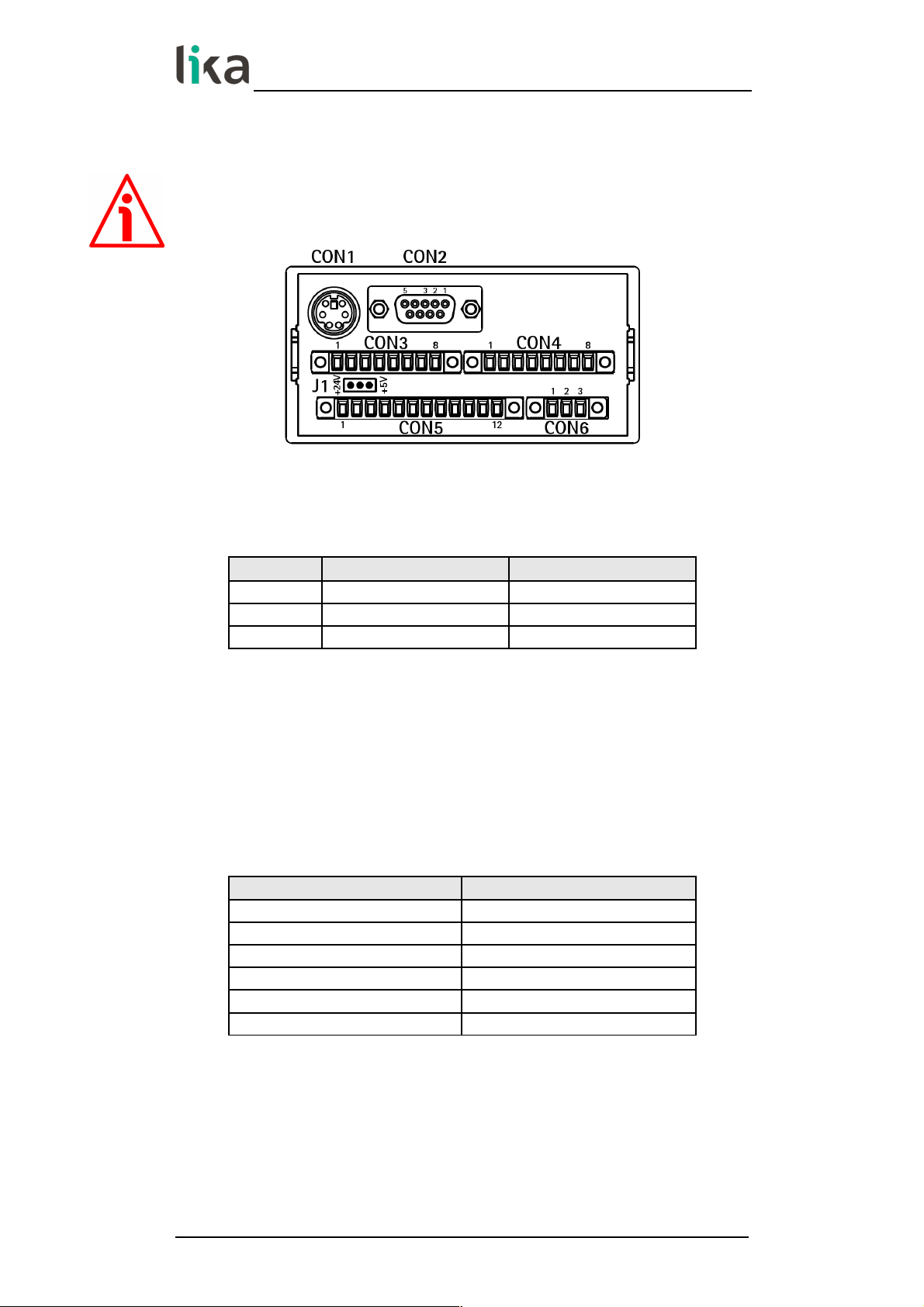
4.1 CON6 connections (Power supply to the display)
Pin Vdc Vac
1 + 24Vdc ±20% 18Vac
2 0Vdc 18Vac
3 P.E. (GND) P.E. (GND)
4.2 CON1 connections (Mini-DIN connector)
Plug the Mini-DIN circular connector of Lika's SM2, SM25 or SM5 sensors on the
backside of the display. For more information refer to the technical
documentation of the magnetic sensors.
4.3 CON2 connections (RS-232 serial interface)
Pin Description
1
not connected
2 RxD
3 TxD
4
not connected
5 0Vdc
6, 7, 8, 9
not connected
For parameter setup via RS-232 interface and software tool please refer to
sections “7 - RS-232 serial interface” on page 53 and “8 - Application software
for PC” on page 65.
MAN LD200 E 2.3.odt 4 - Electrical connections 16 of 72
Page 17

LD200
4.4 CON3 connections (Sine/Cosine 1Vpp)
It allows to connect a Sine/Cosine 1Vpp encoder.
Pin Description
1 0Vdc
2 +5Vdc
3 SIN + (B)
4 SIN - (/B)
5 COS + (A)
6 COS - (/A)
7 REF + (0)
1
8 REF - (/0)
1
1. Zero signal provided by the encoder can be used to activate the Preset
function. See the “5.9 Zero setting (or Preset setting)” section on page
21. To enable it set the EnAbLE 0 parameter in the specific menu to
“ON”, the counting is zero set at the rising edge of the Zero signal.
4.5 CON5 connections (Push-Pull, Line Driver, SSI)
It allows to connect an HTL/Push-Pull or a TTL/Line Driver incremental encoder /
sensor or an SSI interface absolute encoder / sensor.
Pin Description
1 0Vdc
2 +Vdc
1
3 A
4 /A
5 B
6 /B
7 0
2
8 /0
2
9 Data OUT + (SSI)
10 Data OUT - (SSI)
11 Clock IN + (SSI)
12 Clock IN - (SSI)
1. The voltage level of the power supply provided to the connected
encoder can be selected by means of jumper J1. Refer to the “4.6
Jumper J1 (Power supply to the encoder / sensor)” section in the
following page.
2. Zero signal provided by the encoder can be used to activate the Preset
function. See the “5.9 Zero setting (or Preset setting)” section on page
21. To enable it set the EnAbLE 0 parameter in the specific menu to
“ON”, the counting is zero set at the rising edge of the Zero signal.
MAN LD200 E 2.3.odt 4 - Electrical connections 17 of 72
Page 18
LD200
4.6 Jumper J1 (Power supply to the encoder / sensor)
It allows to select the voltage level of the power supply provided to the
connected incremental or SSI encoder / sensor.
Position Description
Left (1-2) +Vdc = +24Vdc @ 1A
Right (2-3) +Vdc = +5Vdc @ 150mA
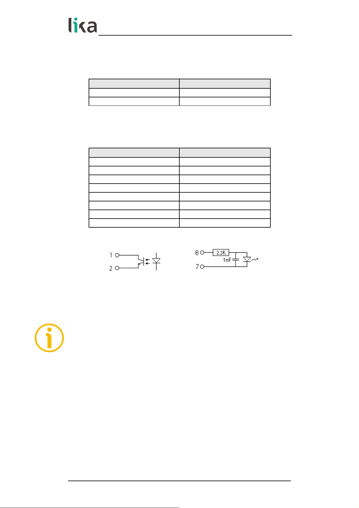
4.7 CON4 connections (Outputs and Input)
Pin Description
1 OUT1 +
2 OUT1 3 OUT2 +
4 OUT2 5 OUT3 +
6 OUT3 7 Preset Input 8 Preset Input +
Digital outputs scheme Digital input scheme
Outputs are open collector with optocouplers, Imax = 25 mA.
Input with optocoupler, Vin max = 30Vdc.
NOTE
Some examples of use of the input and the outputs are available in the “5.10
Preset Input function (CON4, pins 7 and 8)” section on page 22 and in the “5.11
OUT 1, OUT 2, OUT 3 output function (CON4, pins 1 … 6)” section on page 23.
MAN LD200 E 2.3.odt 4 - Electrical connections 18 of 72
Page 19
LD200
5 - Functions
5.1 Start up
At switching on the unit shows the hardware/software version followed by the
device address and the current position.
Hardware version Software version
Version: H xx S yy
Device address (0 … 31): Ad zz (see on page 26)
(used for RS-232 interface connection)
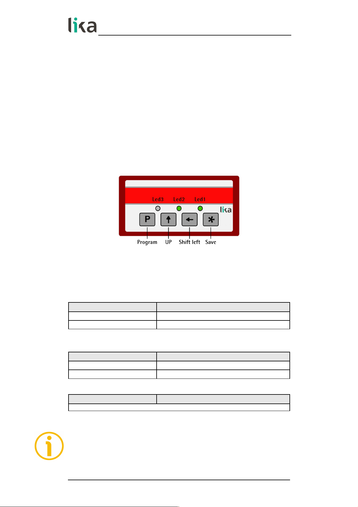
5.2 Function of the LEDs
The display is equipped with three LEDs, their function is described in the
following table.
LED 1 GREEN Description
OFF measurement in millimetres or degrees
ON measurement in inches or fractional inches
See the “5.8 Displaying values in millimetres / degrees / inches / fractional inches” section on
page 21
LED 2 GREEN Description
OFF absolute display mode
ON relative display mode
See the “5.5 Absolute / relative counting mode” section on page 20
LED 3 Description
no function
NOTE
During initialisation, system checks the diagnostic LEDs for proper operation;
therefore they light up for a while.
MAN LD200 E 2.3.odt 5 - Functions 19 of 72
Page 20
LD200
5.3 Function of the keys
Key Function
P
Program: it allows to scroll the items in the menu
UP: it allows to change the value of the selected
digit
Shift left: it allows to select the digit and
sometimes also to change it
*
Save: it allows to save data
Sometimes the keys are used in combination to execute specific functions. Refer
to the following sections.
5.4 Default parameters (factory settings)
Default parameter values are set at the factory by Lika Electronic engineers to
allow the operator to run the device for standard operation in a safe mode. They
are highlighted in BOLD characters in the description of the menus.
The unit can be reset to default values following the steps below:
hold down P and keys while switching the device on (“dEFPAr” must
appear);
zero set the unit (see the “5.9 Zero setting (or Preset setting)“ section on
page 21).
WARNING
This action will reset all parameters to factory default values and customised
settings will be lost. After reset you will have to repeat your individual set-up
procedure.
NOTE
When you need to connect a new device to LD200 please upload the default
parameters of the display before configuring it.
5.5 Absolute / relative counting mode
Press P and * keys to switch from absolute (LED2 = OFF) to relative display
mode (LED2 = ON) and vice versa. Default display mode is “absolute”. Absolute /
relative display mode function is not active with SSI encoders / sensors.
MAN LD200 E 2.3.odt 5 - Functions 20 of 72
Page 21

LD200
5.6 Memory on power down (for incremental and 1Vpp encoders / sensors)
On power down the device automatically stores the last position value on
internal memory.
WARNING
If the position of the connected encoder changes while the power of the display
is off, at the next start up the device will display the last position stored before
switching off, not the new position.
5.7 Offset
The offset value is the difference between the value displayed and the value
that is actually measured. It is added to the current position value to indicate,
for example, the thickness of a tool.
When the current position value is displayed, press key to add the OFFSEt
value to it (“OFFSEt” will be displayed); press key again to confirm.
If the OFFSEt value is already used, press key to subtract it from the current
value (“nO OFS” will be displayed); press key again to confirm.
Display value = current position + PrESEt value + OFFSEt value
For more information on the offset value refer to the OFFSEt parameter in the
specific menus.
5.8 Displaying values in millimetres / degrees / inches / fractional inches
When you press key for 3 s. the display switches the engineering unit from
millimeters/degrees (LED1 = OFF) to inches and further to fractional inches
(LED1 = ON). Default display mode is millimetres.
Refer to the Unit parameter in the specific menus.
5.9 Zero setting (or Preset setting)
The Preset function of the display is meant to show a desired value according to
the position value provided by the connected encoder. The chosen position will
get the value set next to the PrESEt parameter (see the specific menus) and all
the previous and the following positions will get a value according to it. This
function is useful, for example, when we want to pair the zero position of the
application with the zero value that is displayed.
Reset/preset function can be activated in the following ways:
via keyboard: press * key for 3 seconds to access the Preset function
("rESEt" will be displayed). Press P key to exit function (no reset operation is
carried out). Press * key twice to confirm the preset execution ("donE" will
be displayed);
via Preset digital input: see the “5.10 Preset Input function (CON4, pins 7
and 8)” section in the following page;
MAN LD200 E 2.3.odt 5 - Functions 21 of 72
Page 22
LD200
via Encoder Zero signal: refer to the EnAbLE 0 parameter in the specific
menus;
by transmitting the zero setting command via serial port; please refer to the
“7 - RS-232 serial interface” section on page 53;
using the software tool via serial port; please refer to the “8 - Application
software for PC” section on page 65.
For more information on the preset / zero setting function please refer to the
description of the PrESEt parameter in the specific menus.
NOTE
In the absolute counting mode setting the preset/reset affects also the relative
counting mode (see the “5.5 Absolute / relative counting mode” section on page
20).
In the relative counting mode setting the preset/reset does not affect the
absolute counting mode (see the “5.5 Absolute / relative counting mode” section
on page 20).
Display value = 0 + PrESEt value
NOTE
See also OUT 3 output in the “5.11 OUT 1, OUT 2, OUT 3 output function (CON4,
pins 1 … 6)” section on the next page to zero set the connected encoder.
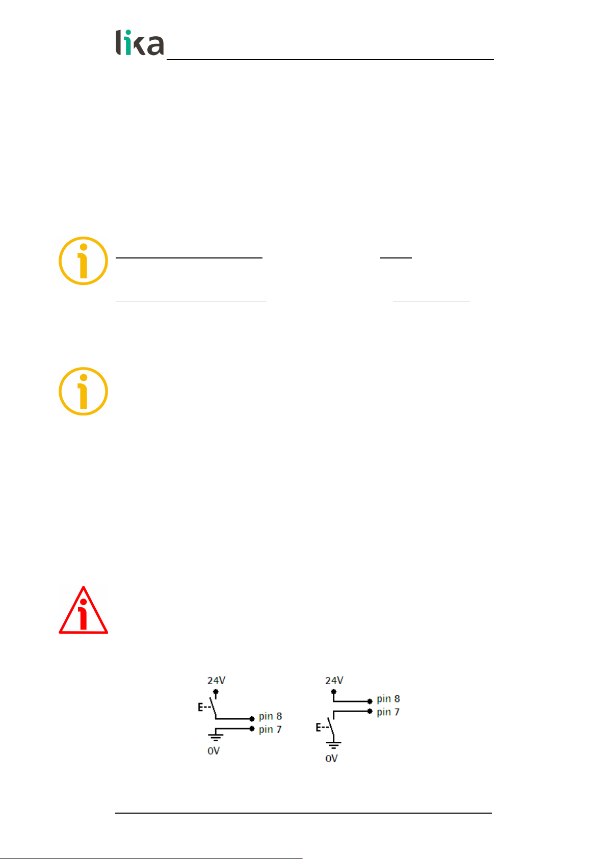
5.10 Preset Input function (CON4, pins 7 and 8)
The Preset input function is used to execute the Set Preset function (see the
previous “5.9 Zero setting (or Preset setting)” section). The Preset signal has to
be at logic level HIGH (Vin between +10Vdc and +30Vdc) for 100 msec.
minimum.
Refer to the EnAb. In parameter in the specific menus to enable this function.
Display value = 0 + PrESEt value
WARNING
Input with optocoupler, Vin max = 30Vdc.
Recommended wiring diagrams:
MAN LD200 E 2.3.odt 5 - Functions 22 of 72
Page 23

LD200
5.10.1 Examples of using the input
In both examples the “Enable Preset Input” function has to be enabled: EnAb. In
parameter = ON.
1 Using a remote button to perform the Preset function of the displayed
value (any encoder / sensor connected):
2 Using OUT 1 (positive limit switch) to send a digital output to the PLC
and simultaneously perform a Preset function of the displayed value:
In this case, the high-level signal sent to the PLC has a duration of 160 ms.
5.11 OUT 1, OUT 2, OUT 3 output function (CON4, pins 1 … 6)
OUT 1 and OUT 2 digital outputs can be used to set upper and lower software
limit switches. See the LIMIt P and LIMIt N parameters in the specific menus.
OUT 3 output can be used for zero setting an SSI absolute encoder / sensor
equipped with zero setting input. When you press the zero setting key or send
the zero setting serial command (see on page 21), OUT 3 is at high logic level for
a duration of 100 ms.
Output Function
OUT 1
HIGH LEVEL if the current position is > LIMIt P
LOW LEVEL if the current position is < LIMIt P
OUT 2
HIGH LEVEL if the current position is < LIMIt N
LOW LEVEL if the current position is > LIMIt N
OUT 3
HIGH LEVEL while the reset command is active
LOW LEVEL during normal operation
MAN LD200 E 2.3.odt 5 - Functions 23 of 72
Page 24

LD200
WARNING
Outputs are open collector with optocouplers, Imax = 25 mA.
Recommended wiring diagrams:
5.11.1 Examples of using the outputs
In the first two examples the “Enable Preset Input” function has to be enabled:
EnAb. In = ON.
1 Using OUT 1 (positive limit switch) to send a digital output to the PLC
and simultaneously perform a Preset function of the displayed value,
the “Enable Preset Input” function has to be enabled: EnAb. In
parameter = ON:
In this case, the high-level signal sent to the PLC has a duration of 160 ms.
2 Using OUT 3 (encoder zero setting output) to send a 24V signal to an
SSI encoder in order to zero set the position by means of the Zero
setting input:
When we use the display zero setting function by means of the zero setting
key or by sending the zero setting serial command (see on page 21), we
contemporaneously transmit to the SSI encoder a 24V signal having a
duration of 100 ms.
MAN LD200 E 2.3.odt 5 - Functions 24 of 72
Page 25

LD200
6 - Setup
6.1 Access to setup menus
Press P key for 3 second to enter the Setup procedure ("SEtUP" will be
displayed):
Then:
press * key to enter the "Basic settings" menu (see the “6.2 Basic settings”
section on page 26);
press key to enter the "Parameter settings" menu (see the “6.3
Parameter settings” section on page 26).
In the "Basic settings" menu both the name of the parameter and the value
appear simultaneously; the value blinks; in the "Parameter settings" menu the
name of the parameter appears first, pressing P key once again the set value
also appears. Press P key to scroll the menu.
Change the value by pressing and/or keys.
Press * to store parameters and values. Displayed value stops blinking if stored
correctly.
Admissible value range for each parameter is listed as follows in the next pages:
[minimum value, maximum value] (default value)
To exit the SETUP procedure scroll the whole list of parameters by pressing P
key.
NOTE
In the LD200 page of Lika's web site www.lika.biz an application software
LD200_Serial_Communication_x_x.exe is available for parameter setup via
RS-232 interface (CON2 connections). Please refer to the “7 - RS-232 serial
interface” section on page 53 and to the “8 - Application software for PC”
section on page 65.
MAN LD200 E 2.3.odt 6 - Setup 25 of 72
Page 26

LD200
6.2 Basic settings
Ad
Device address [0, 31] (def: 0)
It sets the address of the device needed for RS-232 communication. Please refer
to the “7 - RS-232 serial interface” section on page 53 and to the “8 Application software for PC” section on page 65.
L_int
Light intensity of the display [0, 15] (def: 10)
It sets the light intensity of 7 segment LED display. Use and keys to
change the parameter value.
0 = minimum intensity
...
10 = normal intensity
...
15 = maximum intensity
6.3 Parameter settings
d_tyPE
Device type
[E_Incr, E_1VPP, E_SSI_, M_SEnS, M_Incr, M_1VPP, M_SSI_] (def: E_Incr)
It sets the type of encoder/sensor connected to the display.
d_tyPE Type of transducer
E_Incr
AB0 incremental rotary encoder
Refer to “6.4 AB0 incremental rotary encoder“ section on page 27
E_1VPP
1Vpp Sine/Cosine rotary encoder
Refer to “6.5 1Vpp Sine/Cosine rotary encoder” section on page 30
E_SSI_
SSI interface absolute rotary encoder
Refer to “6.6 Absolute rotary encoder with SSI interface” section on on page 33
M_SEnS
SM2, SM25, SM5 magnetic linear sensors
Refer to “6.7 Lika's SM2, SM25, SM5 magnetic sensors” section on on page 40
M_Incr
AB0 incremental linear encoder/sensor
Refer to “6.8 AB0 incremental linear encoder/sensor” section on on page 43
M_1VPP
1Vpp Sine/Cosine linear encoder/sensor
Refer to “6.9 1Vpp Sine/Cosine linear encoder/sensor” section on on page 46
M_SSI_
SSI interface absolute linear encoder/sensor
Refer to “6.10 Absolute linear encoder/sensor with SSI interface” section on on page 49
NOTE
Each device type has appropriate parameters only relevant to the specific type
of encoder/sensor. The choice of the connected device also changes the list of
the available parameters.
MAN LD200 E 2.3.odt 6 - Setup 26 of 72
Page 27

LD200
6.4 AB0 incremental rotary encoder
d_tyPE = E_Incr. List of parameters of incremental rotary encoders with
HTL/Push-Pull or TTL/Line Driver circuit (with or without complementary signals).
For connection refer to the “4.5 CON5 connections (Push-Pull, Line Driver, SSI)”
section on page 17.
PPr
Pulses per revolution [1, 99999999] (def: 4096)
Number of pulses per revolution (PPR) provided by the encoder.
diSt_r
Display value per turn [1, 99999999] (def: 4096)
Value to be displayed after 1 revolution of the encoder.
If diSt_r is > PPr * 4, a “jump” in the display value will occur.
MOd 360
360° display mode [OFF, On] (def: OFF)
It sets the angular display mode (expressed in degrees: ...0.0°...359.9°...0.0°...).
If MOd 360 = ON, the display value per turn (see diSt_r parameter) has to be
set to 360, 3600 or 36000 depending on the required decimal separator
position. Set Unit parameter = U_dEc.
OFF = angular display mode not active
On = angular display mode active
Unit
Unit of measurement [U_dEc, Inch, Inch_F] (def: U_dEc)
It sets the unit of measurement of the display mode to millimeters/degrees,
inches or fractional inches. See also the “5.8 Displaying values in millimetres /
degrees / inches / fractional inches” section on page 21.
U_dEc = mm/degrees (“degrees” only if MOd 360 = On)
Inch = inches
Inch_F = fractional inches (eg. 12.31.64 = 12" 31/64)
EnAbLE 0
Enable Zero signal [OFF, On] (def: OFF)
It is used to activate the Preset function of the display by means of the zero
signal of the encoder (pins 7 and 8 of CON5, see on page 17). See the “5.9 Zero
setting (or Preset setting)” section on page 21.
If EnAbLE 0 is set to “On”, the display value is zero set at the rising edge of the
Zero signal.
OFF = Zero signal not enabled
On = Zero signal enabled
MAN LD200 E 2.3.odt 6 - Setup 27 of 72
Page 28

LD200
dir
Counting direction [uP, dn] (def: uP)
It sets the counting direction of the display value.
uP = standard counting direction = count up when the encoder shaft turns
clockwise (viewed from the shaft side)
dn = inverted counting direction
dEciMALS
Decimal separator [0, 3] (def: 0)
It changes the position of the decimal separator. This setting does not affect
other parameters.
0 = 00000000
…
3 = 00000.000 (0000.0000 if Unit = Inch)
PrESEt
Preset value [-99999999, 99999999] (def: 0)
The Preset function of the display is meant to show a desired value according to
the position value provided by the connected encoder. The chosen position will
get the value set next to this PrESEt parameter and all the previous and the
following positions will get a value according to it. This function is useful, for
example, when we want to pair the zero position of the application with the
zero value that is displayed. To execute the preset see the “5.9 Zero setting (or
Preset setting)” section on page 21. This parameter is always expressed and
calculated in metric measurement unit (millimeters).
LIMIt P
Positive limit switch [-99999999, 99999999] (def: 0)
Value of positive limit switch.
Output OUT 1 (see on page 18) is active (HIGH LEVEL) when the current position
is greater than the set value. This parameter is always expressed and calculated
in metric measurement unit (millimeters). See also the “5.11 OUT 1, OUT 2, OUT
3 output function (CON4, pins 1 … 6)” section on page 23.
LIMIt N
Negative limit switch [-99999999, 99999999] (def: 0)
Value of negative limit switch.
Output OUT 2 (see on page 18) is active (HIGH LEVEL) when the current position
is less than the set value. This parameter is always expressed and calculated in
metric measurement unit (millimeters). See also the “5.11 OUT 1, OUT 2, OUT 3
output function (CON4, pins 1 … 6)” section on page 23.
MAN LD200 E 2.3.odt 6 - Setup 28 of 72
Page 29

LD200
OFFSEt
Offset value [-99999999, 99999999] (def: 0)
The offset value is the difference between the value displayed and the value
that is actually measured. It is added to the current position value to indicate,
for example, the thickness of a tool. This value is added to the current position
by pressing key. This parameter is always expressed and calculated in metric
measurement unit (millimeters). See also the “5.7 Offset” section on page 21.
Position = current position + OFFSEt value
EnAb. In
Enable Preset Input [OFF, On] (def: OFF)
If it is set to “On”, the Preset digital input can be used to activate the Preset
function (see the “5.10 Preset Input function (CON4, pins 7 and 8)” section on
page 22).
OFF = Input not enabled
On = Input enabled
EXAMPLE
An I58-H-500ZCU46L2 encoder (500 PPR) has to display 10,00 mm at each
complete turn, activate the positive limit switch at 30,00 mm and enable the
input function.
d_tyPE = E_Incr dEciMALS = 2
PPr = 500 (encoder feature) PrESEt = 0
diSt_r = 1000 LIMIt P = 2999
MOd 360 = OFF LIMIt N = 0
Unit = U_dec OFFSEt = 0
EnAbLE 0 = OFF EnAb. In = ON
dir = Up
EXAMPLE
We need to connect the following incremental rotary encoder: I28-Y100BNF25Lx (100 PPR) and display 100 mm at each complete turn.
d_tyPE = E_Incr dEciMALS = 0
PPr = 100 (encoder feature) PrESEt = 0
diSt_r = 100 LIMIt P = 0
MOd 360 = OFF LIMIt N = 0
Unit = U_dec OFFSEt = 0
EnAbLE 0 = OFF EnAb. In = OFF
dir = Up
MAN LD200 E 2.3.odt 6 - Setup 29 of 72
Page 30

LD200
6.5 1Vpp Sine/Cosine rotary encoder
d_tyPE = E_1VPP. List of parameters of rotary encoders with 1Vpp Sine/Cosine
output circuit. For connection refer to the “4.4 CON3 connections (Sine/Cosine
1Vpp)” section on page 17.
PPr
Pulses per revolution [1, 99999999] (def: 4096)
Number of pulses per revolution (Sine/Cosine signals) provided by the encoder.
diSt_r
Display value per turn [1, 99999999] (def: 4096)
Value to be displayed after 1 revolution of the encoder.
If diSt_r is > PPr * 1024, a “jump” in the display value will occur. The max.
interpolation factor is 5,000.
MOd 360
360° display mode [OFF, On] (def: OFF)
It sets the angular display mode (expressed in degrees: ...0.0°...359.9°...0.0°...).
If MOd 360 = ON, the display value per turn (see diSt_r parameter) has to be
set to 360, 3600 or 36000 depending on the required decimal separator
position. Set Unit parameter = U_dec.
OFF = angular display mode not active
On = angular display mode active
Unit
Unit of measurement [U_dEc, Inch, Inch_F] (def: U_dEc)
It sets the unit of measurement of the display mode to millimeters/degrees,
inches or fractional inches. See also the “5.8 Displaying values in millimetres /
degrees / inches / fractional inches” section on page 21.
U_dEc = mm/degrees (“degrees” only if MOd 360 = On)
Inch = inches
Inch_F = fractional inches (eg. 12.31.64 = 12" 31/64)
EnAbLE 0
Enable Zero signal [OFF, On] (def: OFF)
It is used to activate the Preset function of the display by means of the zero
signal of the encoder (pins 7 and 8 of CON3, see on page 17). See the “5.9 Zero
setting (or Preset setting)” section on page 21.
If EnAbLE 0 is set to “On”, the display value is zero set at the rising edge of the
Zero signal.
OFF = Zero signal not enabled
On = Zero signal enabled
MAN LD200 E 2.3.odt 6 - Setup 30 of 72
Page 31

LD200
dir
Counting direction [uP, dn] (def: uP)
It sets the counting direction of the display value.
uP = standard counting direction = count up when the encoder shaft turns
clockwise (viewed from the shaft side)
dn = inverted counting direction
dEciMALS
Decimal separator [0, 3] (def: 0)
It changes the position of the decimal separator. This setting does not affect
other parameters.
0 = 00000000
…
3 = 00000.000 (0000.0000 if Unit = Inch)
PrESEt
Preset value [-99999999, 99999999] (def: 0)
The Preset function of the display is meant to show a desired value according to
the position value provided by the connected encoder. The chosen position will
get the value set next to this PrESEt parameter and all the previous and the
following positions will get a value according to it. This function is useful, for
example, when we want to pair the zero position of the application with the
zero value that is displayed. To execute the preset see the “5.9 Zero setting (or
Preset setting)” section on page 21. This parameter is always expressed and
calculated in metric measurement unit (millimeters).
LIMIt P
Positive limit switch [-99999999, 99999999] (def: 0)
Value of positive limit switch.
Output OUT 1 (see on page 18) is active (HIGH LEVEL) when the current position
is greater than the set value. This parameter is always expressed and calculated
in metric measurement unit (millimeters). See also the “5.11 OUT 1, OUT 2, OUT
3 output function (CON4, pins 1 … 6)” section on page 23.
LIMIt N
Negative limit switch [-99999999, 99999999] (def: 0)
Value of negative limit switch.
Output OUT 2 (see on page 18) is active (HIGH LEVEL) when the current position
is less than the set value. This parameter is always expressed and calculated in
metric measurement unit (millimeters). See also the “5.11 OUT 1, OUT 2, OUT 3
output function (CON4, pins 1 … 6)” section on page 23.
MAN LD200 E 2.3.odt 6 - Setup 31 of 72
Page 32

LD200
OFFSEt
Offset value [-99999999, 99999999] (def: 0)
The offset value is the difference between the value displayed and the value
that is actually measured. It is added to the current position value to indicate,
for example, the thickness of a tool. This value is added to the current position
by pressing key. This parameter is always expressed and calculated in metric
measurement unit (millimeters). See also the “5.7 Offset” section on page 21.
Position = current position + OFFSEt value
EnAb. In
Enable Preset Input [OFF, On] (def: OFF)
If it is set to “On”, the Preset digital input can be used to activate the Preset
function (see the “5.10 Preset Input function (CON4, pins 7 and 8)” section on
page 22).
OFF = Input not enabled
On = Input enabled
EXAMPLE
An I58-V-1024ZCU16 encoder (1024 sinusoids each turn) has to display 360.00°
each turn and activate the positive limit switch at 359.99°.
d_tyPE = E_1Vpp dEciMALS = 2
PPr = 1024 (encoder feature) PrESEt = 0
diSt_r = 36000 LIMIt P = 35998
MOd 360 = ON LIMIt N = 0
Unit = U_dec OFFSEt = 0
EnAbLE 0 = OFF EnAb. In = OFF
dir = Up
MAN LD200 E 2.3.odt 6 - Setup 32 of 72
Page 33

LD200
6.6 Absolute rotary encoder with SSI interface
d_tyPE = E_SSI_. List of parameters of singleturn/multiturn absolute rotary
encoders with SSI interface and “Tree” or LSB Right Aligned” protocol. For
connection refer to the “4.5 CON5 connections (Push-Pull, Line Driver, SSI)”
section on page 17.
NOTE
If you need to connect a rotary encoder with “MSB Left Aligned” protocol and
25-bit max. resolution, refer to the “6.6.1 Connecting an SSI encoder with “MSB
Left Aligned” protocol“ section on page 36.
NOTE
Absolute/relative display mode function is not active in this device type.
ForMAt
Number of clocks for SSI [13-25, 25-32] (def: 13-25)
It sets the number of clocks required by the SSI protocol.
13-25 = 13 or 25 clocks (singleturn/multiturn encoders)
25-32 = 25 or 32 clocks (extended protocol up to 32 bits)
WARNING
Extended format only with "LSB Right Aligned protocol" (see Prtcl parameter).
PPr
Resolution per turn [1, 33554432] (def: 4096)
Number of counts per revolution (cpr) provided by the absolute encoder.
n_turnS
Number of turns [1, 4096] (def: 4096)
Number of turns of the absolute encoder. For singleturn encoders set 1. With
programmable encoders set the number of hardware revolutions, not the
programmed value.
diSt_r
Display value per turn [1, 99999999] (def: 4096)
Value to be displayed after 1 revolution of the encoder.
If diSt_r is > PPr, a “jump” in the display value will occur.
MAN LD200 E 2.3.odt 6 - Setup 33 of 72
Page 34

LD200
Prtcl
SSI protocol [SHIFt, trEE] (def: trEE)
Type of SSI protocol used by the connected encoder.
SHIFt = LSB Right Aligned protocol
trEE = Tree format protocol
NOTE
If you need to configure an SSI encoder with “MSB Left Aligned” protocol and
25-bit max. resolution, refer to the “6.6.1 Connecting an SSI encoder with “MSB
Left Aligned” protocol“ section on page 36.
codE
Encoder output code [GrAy, bin] (def: GrAy)
Output code of the encoder.
GrAy = Gray code (eg. Lika order code "GS" or "GR")
bin = Binary code (eg. Lika order code "BS" or "BR")
Unit
Unit of measurement [U_dEc, Inch, Inch_F] (def: U_dEc)
It sets the unit of measurement of the display mode to millimeters, inches or
fractional inches. See also the “5.8 Displaying values in millimetres / degrees /
inches / fractional inches” section on page 21.
U_dEc = mm
Inch = inches
Inch_F = fractional inches (eg. 12.31.64 = 12" 31/64)
dir
Counting direction [uP, dn] (def: uP)
It sets the counting direction of the display value.
uP = standard counting direction = count up when the encoder shaft turns
clockwise (viewed from the shaft side)
dn = inverted counting direction
dEciMALS
Decimal separator [0, 3] (def: 0)
It changes the position of the decimal separator. This setting does not affect
other parameters.
0 = 00000000
…
3 = 00000.000 (0000.0000 if Unit = Inch)
MAN LD200 E 2.3.odt 6 - Setup 34 of 72
Page 35

LD200
PrESEt
Preset value [-99999999, 99999999] (def: 0)
The Preset function of the display is meant to show a desired value according to
the position value provided by the connected encoder. The chosen position will
get the value set next to this PrESEt parameter and all the previous and the
following positions will get a value according to it. This function is useful, for
example, when we want to pair the zero position of the application with the
zero value that is displayed. To execute the preset see the “5.9 Zero setting (or
Preset setting)” section on page 21. This parameter is always expressed and
calculated in metric measurement unit (millimeters).
NOTE
Refer also to the “5.11 OUT 1, OUT 2, OUT 3 output function (CON4, pins 1 … 6)”
section on page 23 for contemporaneously resetting the encoder via OUT 3
output (if the encoder is equipped with the Zero setting input).
LIMIt P
Positive limit switch [-99999999, 99999999] (def: 0)
Value of positive limit switch.
Output OUT 1 (see on page 18) is active (HIGH LEVEL) when the current position
is greater than the set value. This parameter is always expressed and calculated
in metric measurement unit (millimeters). See also the “5.11 OUT 1, OUT 2, OUT
3 output function (CON4, pins 1 … 6)” section on page 23.
LIMIt N
Negative limit switch [-99999999, 99999999] (def: 0)
Value of negative limit switch.
Output OUT 2 (see on page 18) is active (HIGH LEVEL) when the current position
is less than the set value. This parameter is always expressed and calculated in
metric measurement unit (millimeters). See also the “5.11 OUT 1, OUT 2, OUT 3
output function (CON4, pins 1 … 6)” section on page 23.
OFFSEt
Offset value [-99999999, 99999999] (def: 0)
The offset value is the difference between the value displayed and the value
that is actually measured. It is added to the current position value to indicate,
for example, the thickness of a tool. This value is added to the current position
by pressing key. This parameter is always expressed and calculated in metric
measurement unit (millimeters). See also the “5.7 Offset” section on page 21.
Position = current position + OFFSEt value
MAN LD200 E 2.3.odt 6 - Setup 35 of 72
Page 36

LD200
EnAb. In
Enable Preset Input [OFF, On] (def: OFF)
If it is set to “On”, the Preset digital input can be used to activate the Preset
function (see the “5.10 Preset Input function (CON4, pins 7 and 8)” section on
page 22).
OFF = Input not enabled
On = Input enabled
EXAMPLE
The absolute position of an AM5812/4096GS-10 encoder (4096 cpr, 4096 turns,
Gray code and "Tree” protocol) has to display 20,00 mm at each complete turn,
activate the positive limit switch at 50,00 mm and enable the input function.
d_tyPE = E_SSI_ Prtcl = Tree (encoder feature) PrESEt = 0
ForMAt = 13-25 codE = Gray (encoder feature) LIMIt P = 4999
PPr = 4096 (encoder feature) Unit = U_dec LIMIt N = 0
n_turnS = 4096 (encoder feature) dir = Up OFFSEt = 0
diSt_r = 2000 dEciMALS = 2 EnAb. In = ON
EXAMPLE
We need to connect the following absolute rotary encoder: MM3612/8192GB-6
(4096 cpr, 8192 turns, Gray code and "LSB Right Aligned” protocol).
d_tyPE = E_SSI_ Prtcl = Shift (encoder feature) PrESEt = 0
ForMAt = 13-25 codE = Gray (encoder feature) LIMIt P = 0
PPr = 4096 (encoder feature) Unit = U_dec LIMIt N = 0
n_turnS = 8192 (encoder feature) dir = Up OFFSEt = 0
diSt_r = 4096 dEciMALS = 0 EnAb. In = OFF
6.6.1 Connecting an SSI encoder with “MSB Left Aligned” protocol
You can set the LD200 display for connection to a rotary or linear encoder
equipped with “MSB Left Aligned” SSI serial protocol having a max.
resolution of 25 bits.
If the total hardware resolution of the connected encoder is between 12 and
25 bits (transmission of 25 clocks) please set the parameters as follows:
d_tyPE = E_SSI_ n_turnS = 4096, see the table below
ForMAt = 13-25 diSt_r = the same as PPr, see the table below
PPr = see the table below Prtcl = Tree
MAN LD200 E 2.3.odt 6 - Setup 36 of 72
Page 37

LD200
Number of bits PPr n_turnS diSt_r
25
8192 4096 8192
24
4096 4096 4096
23
2048 4096 2048
22
1024 4096 1024
21
512 4096 512
20
256 4096 256
19
128 4096 128
18
64 4096 64
17
32 4096 32
16
16 4096 16
15
8 4096 8
14
4 4096 4
13
2 4096 2
If the total hardware resolution of the connected encoder is between 2 and
12 bits (transmission of 13 clocks) please set the parameters as follows:
d_tyPE = E_SSI_ n_turnS = 1, see the table below
ForMAt = 13-25 diSt_r = the same as PPr, see the table below
PPr = see the table below Prtcl = Tree
Number of bits PPr n_turnS diSt_r
12
4096 1 4096
11
2048 1 2048
10
1024 1 1024
9
512 1 512
8
256 1 256
7
128 1 128
6
64 1 64
5
32 1 32
4
16 1 16
3
8 1 8
2
4 1 4
MAN LD200 E 2.3.odt 6 - Setup 37 of 72
Page 38

LD200
The total hardware resolution of the connected encoder is: cpr + number of
turns.
In a rotary encoder the cpr is expressed in bits in the order code while the
number of turns must be translated into bits.
For example: AM5812/4096...: “12” is the number of bits of the counts per
revolution (i.e. 212 = 4096 cpr); “4096” is the number of turns, that is: 212. So the
number of turns expressed in bits is “12”.
In the example the total hardware resolution will be 12 + 12 = 24 bits.
In a linear encoder the number of bits is calculated considering the maximum
number of information the encoder can provide to output and cannot be
directly gathered from the order code. WARNING: please do not add to sum any
additional bit (such as an error bit). The maximum number of information
depends on the measuring length of the application and the resolution of the
encoder and is calculated as follows:
Maximum number of information =
measuring length
resolution
EXAMPLE
Let's say we need to connect the following linear encoder: SMAX-BG-100. Its
resolution is 0.1 mm (see the order code). The maximum measuring length of
the SMAX linear encoder over the MTAX tape is 600 mm (see the order code of
the tape).
So the encoder will provide the following maximum number of information:
Maximum number of information =
600
= 6,000
0.1
It is clear that if you mount only half the tape (i.e. 300 mm), then the maximum
number of information that the encoder can provide will be down to half (3,000
information).
To translate the number of information into bits, you must “round up” the value
to the next highest power of 2, that is: 6,000 = 213 (8,192). The number of bits to
consider will be “13”.
For further information please refer to the specific technical documentation of
the connected encoder.
EXAMPLE
Using the parameters dedicated to the absolute rotary encoders with SSI
interface, we are able to configure the display for connection to an SMA2 linear
encoder (resolution from 1 µm to 50 µm, Gray or binary code and “MSB Left
Aligned” protocol). Please consider that the maximum measuring length of the
SMA2 encoder over the MTA2 tape is 8,160 mm.
MAN LD200 E 2.3.odt 6 - Setup 38 of 72
Page 39

LD200
d_tyPE = E_SSI_ n_turnS = 4096
ForMAt = 13-25 diSt_r = the same as PPr
PPr = 2048 if resolution = 1 µm Prtcl = Tree
PPr = 1024 if resolution = 2 µm codE = Gray or Bin
PPr = 512 if resolution = 5 µm dir = Up or Dn
PPr = 256 if resolution = 10 µm
PPr = 64 if resolution = 50 µm
For example if we connect an SMA2-GG1-1-...:
Maximum number of information =
8,160
= 8,160,000
0.001
8,160,000 = 2
23
Thus:
n_turnS = 4,096 = 2
12
PPr = 223 – 212 = 211 = 2,048, as you can see in the table above.
MAN LD200 E 2.3.odt 6 - Setup 39 of 72
Page 40

LD200
6.7 Lika's SM2, SM25, SM5 magnetic sensors
d_tyPE = M_SEnS. List of parameters of Lika's SM2, SM25 or SM5 series
magnetic sensors with Mini-DIN connector. For connection refer to the “4.2
CON1 connections (Mini-DIN connector)” section on page 16.
Pitch
Type of sensor/tape [10, 20, 25, 32, 40, 50] (def: 50)
It sets the type of SM sensor + MT tape used. The number to be set indicates the
pole pitch of the sensor and tape expressed in tenths of a millimeter.
20 = SM2 sensor + MT20 tape (2 mm pole pitch)
25 = SM25 sensor + MT25 tape (2.5 mm pole pitch)
50 = SM5 sensor + MT50 tape (5 mm pole pitch)
rES
Resolution [0.001, 0.005, 0.01, 0.05, 0.1, 0.5, 1] (def: 0.001)
It sets the linear resolution expressed in millimeters to be used to display the
position value.
1 = 1 mm
...
0.001 = 0.001 mm
Unit
Unit of measurement [U_dEc, Inch, Inch_F] (def: U_dEc)
It sets the unit of measurement of the display mode to millimeters, inches or
fractional inches. See also the “5.8 Displaying values in millimetres / degrees /
inches / fractional inches” section on page 21.
U_dEc = mm
Inch = inches
Inch_F = fractional inches (eg. 12.31.64 = 12" 31/64)
dir
Counting direction [uP, dn] (def: uP)
It sets the counting direction of the display value.
uP = standard counting direction = count up when the sensor moves over the
tape in the standard direction as explained in the manual
dn = inverted counting direction
PrESEt
Preset value [-99999999, 99999999] (def: 0)
The Preset function of the display is meant to show a desired value according to
the position value provided by the connected encoder. The chosen position will
get the value set next to this PrESEt parameter and all the previous and the
following positions will get a value according to it. This function is useful, for
example, when we want to pair the zero position of the application with the
MAN LD200 E 2.3.odt 6 - Setup 40 of 72
Page 41

LD200
zero value that is displayed. To execute the preset see the “5.9 Zero setting (or
Preset setting)” section on page 21. This parameter is always expressed and
calculated in metric measurement unit (millimeters).
LIMIt P
Positive limit switch [-99999999, 99999999] (def: 0)
Value of positive limit switch.
Output OUT 1 (see on page 18) is active (HIGH LEVEL) when the current position
is greater than the set value. This parameter is always expressed and calculated
in metric measurement unit (millimeters). See also the “5.11 OUT 1, OUT 2, OUT
3 output function (CON4, pins 1 … 6)” section on page 23.
LIMIt N
Negative limit switch [-99999999, 99999999] (def: 0)
Value of negative limit switch.
Output OUT 2 (see on page 18) is active (HIGH LEVEL) when the current position
is less than the set value. This parameter is always expressed and calculated in
metric measurement unit (millimeters). See also the “5.11 OUT 1, OUT 2, OUT 3
output function (CON4, pins 1 … 6)” section on page 23.
OFFSEt
Offset value [-99999999, 99999999] (def: 0)
The offset value is the difference between the value displayed and the value
that is actually measured. It is added to the current position value to indicate,
for example, the thickness of a tool. This value is added to the current position
by pressing key. This parameter is always expressed and calculated in metric
measurement unit (millimeters). See also the “5.7 Offset” section on page 21.
Position = current position + OFFSEt value
EnAb. In
Enable Preset Input [OFF, On] (def: OFF)
If it is set to “On”, the Preset digital input can be used to activate the Preset
function (see the “5.10 Preset Input function (CON4, pins 7 and 8)” section on
page 22).
OFF = Input not enabled
On = Input enabled
MAN LD200 E 2.3.odt 6 - Setup 41 of 72
Page 42

LD200
EXAMPLE
An SM5-R-2 sensor is connected to an LD200 display and has to display
positions with a resolution of 0.01 mm, a tool correction factor of 5 mm and
software limit switches at 0 and 1.5 meter.
d_tyPE = M_Sens PrESEt = 0
Pitch = 50 (sensor feature) LIMIt P = 149999
rES = 0.01 mm LIMIt N = 0
Unit = U_dec OFFSEt = 500
dir = Up EnAb. In = OFF
MAN LD200 E 2.3.odt 6 - Setup 42 of 72
Page 43

LD200
6.8 AB0 incremental linear encoder/sensor
d_tyPE = M_Incr. List of parameters of incremental linear encoders and sensors
with HTL/Push-Pull or TTL/Line Driver output (with or without complementary
signals). For connection refer to the “4.5 CON5 connections (Push-Pull, Line
Driver, SSI)” section on page 17.
rES
Resolution [0.001, 0.002, 0.005, 0.01, 0.02, 0.025, 0.04, 0.05, 0.1, 0.25, 0.5] (def:
0.001)
It sets the linear resolution expressed in millimeters to be used to display the
position value.
0.5 = 0.5 mm
...
0.001 = 0.001 mm
Unit
Unit of measurement [U_dEc, Inch, Inch_F] (def: U_dEc)
It sets the unit of measurement of the display mode to millimeters, inches or
fractional inches. See also the “5.8 Displaying values in millimetres / degrees /
inches / fractional inches” section on page 21.
U_dEc = mm
Inch = inches
Inch_F = fractional inches (eg. 12.31.64 = 12" 31/64)
EnAbLE 0
Enable Zero signal [OFF, On] (def: OFF)
It is used to activate the Preset function of the display by means of the zero
signal of the sensor (pins 7 and 8 of CON5, see on page 17). See the “5.9 Zero
setting (or Preset setting)” section on page 21.
If EnAbLE 0 is set to “On”, the display value is zero set at the rising edge of the
Zero signal.
We recommend sensors with “R” Reference order code to be used.
OFF = Zero signal not enabled
On = Zero signal enabled
dir
Counting direction [uP, dn] (def: uP)
It sets the counting direction of the display value.
uP = standard counting direction = count up when the sensor moves over the
tape in the standard direction as explained in the manual
dn = inverted counting direction
MAN LD200 E 2.3.odt 6 - Setup 43 of 72
Page 44

LD200
PrESEt
Preset value [-99999999, 99999999] (def: 0)
The Preset function of the display is meant to show a desired value according to
the position value provided by the connected encoder. The chosen position will
get the value set next to this PrESEt parameter and all the previous and the
following positions will get a value according to it. This function is useful, for
example, when we want to pair the zero position of the application with the
zero value that is displayed. To execute the preset see the “5.9 Zero setting (or
Preset setting)” section on page 21. This parameter is always expressed and
calculated in metric measurement unit (millimeters).
LIMIt P
Positive limit switch [-99999999, 99999999] (def: 0)
Value of positive limit switch.
Output OUT 1 (see on page 18) is active (HIGH LEVEL) when the current position
is greater than the set value. This parameter is always expressed and calculated
in metric measurement unit (millimeters). See also the “5.11 OUT 1, OUT 2, OUT
3 output function (CON4, pins 1 … 6)” section on page 23.
LIMIt N
Negative limit switch [-99999999, 99999999] (def: 0)
Value of negative limit switch.
Output OUT 2 (see on page 18) is active (HIGH LEVEL) when the current position
is less than the set value. This parameter is always expressed and calculated in
metric measurement unit (millimeters). See also the “5.11 OUT 1, OUT 2, OUT 3
output function (CON4, pins 1 … 6)” section on page 23.
OFFSEt
Offset value [-99999999, 99999999] (def: 0)
The offset value is the difference between the value displayed and the value
that is actually measured. It is added to the current position value to indicate,
for example, the thickness of a tool. This value is added to the current position
by pressing key. This parameter is always expressed and calculated in metric
measurement unit (millimeters). See also the “5.7 Offset” section on page 21.
Position = current position + OFFSEt value
EnAb. In
Enable Preset Input [OFF, On] (def: OFF)
If it is set to “On”, the Preset digital input can be used to activate the Preset
function (see the “5.10 Preset Input function (CON4, pins 7 and 8)” section on
page 22).
OFF = Input not enabled
On = Input enabled
MAN LD200 E 2.3.odt 6 - Setup 44 of 72
Page 45

LD200
EXAMPLE
The measurement values of an SME51-Y-2-10-I-L2-B magnetic sensor paired
with an MT50 tape have to be displayed.
d_tyPE = M_Incr PrESEt = 0
rES = 0.01 mm LIMIt P = 0
Unit = U_dec LIMIt N = 0
EnAbLE 0 = OFF OFFSEt = 0
dir = Up EnAb. In = OFF
MAN LD200 E 2.3.odt 6 - Setup 45 of 72
Page 46

LD200
6.9 1Vpp Sine/Cosine linear encoder/sensor
d_tyPE = M_1VPP. List of parameters of incremental linear encoders and
sensors with 1Vpp Sine/Cosine output. For connection refer to the “4.4 CON3
connections (Sine/Cosine 1Vpp)” section on page 17.
Pitch
Pitch of the sensor/tape [10, 20, 25, 32, 40, 50] (def: 50)
It sets the type of sensor and tape used. Value indicates the pole pitch of the
sensor and tape expressed in tenths of a millimeter.
10 = MT10 tape (1 mm pole pitch)
...
50 = MT50 tape (5 mm pole pitch)
rES
Resolution [0.005, 0.01, 0.02, 0.025, 0.04, 0.05, 0.1, 0.25, 0.5] (def: 0.005)
It sets the linear resolution expressed in millimeters to be used to display the
position value.
0.5 = 0.5 mm
...
0.005 = 0.005 mm
Unit
Unit of measurement [U_dEc, Inch, Inch_F] (def: U_dEc)
It sets the unit of measurement of the display mode to millimeters, inches or
fractional inches. See also the “5.8 Displaying values in millimetres / degrees /
inches / fractional inches” section on page 21.
U_dEc = mm
Inch = inches
Inch_F = fractional inches (eg. 12.31.64 = 12" 31/64)
EnAbLE 0
Enable Zero signal [OFF, On] (def: OFF)
It is used to activate the Preset function of the display by means of the zero
signal of the sensor (pins 7 and 8 of CON3, see on page 17). See the “5.9 Zero
setting (or Preset setting)” section on page 21.
If EnAbLE 0 is set to “On”, the display value is zero set at the rising edge of the
Zero signal.
We recommend sensors with “R” Reference order code to be used.
OFF = Zero signal not enabled
On = Zero signal enabled
MAN LD200 E 2.3.odt 6 - Setup 46 of 72
Page 47

LD200
dir
Counting direction [uP, dn] (def: uP)
It sets the counting direction of the display value.
uP = standard counting direction = count up when the sensor moves over the
tape in the standard direction as explained in the manual
dn = inverted counting direction
PrESEt
Preset value [-99999999, 99999999] (def: 0)
The Preset function of the display is meant to show a desired value according to
the position value provided by the connected encoder. The chosen position will
get the value set next to this PrESEt parameter and all the previous and the
following positions will get a value according to it. This function is useful, for
example, when we want to pair the zero position of the application with the
zero value that is displayed. To execute the preset see the “5.9 Zero setting (or
Preset setting)” section on page 21. This parameter is always expressed and
calculated in metric measurement unit (millimeters).
LIMIt P
Positive limit switch [-99999999, 99999999] (def: 0)
Value of positive limit switch.
Output OUT 1 (see on page 18) is active (HIGH LEVEL) when the current position
is greater than the set value. This parameter is always expressed and calculated
in metric measurement unit (millimeters). See also the “5.11 OUT 1, OUT 2, OUT
3 output function (CON4, pins 1 … 6)” section on page 23.
LIMIt N
Negative limit switch [-99999999, 99999999] (def: 0)
Value of negative limit switch.
Output OUT 2 (see on page 18) is active (HIGH LEVEL) when the current position
is less than the set value. This parameter is always expressed and calculated in
metric measurement unit (millimeters). See also the “5.11 OUT 1, OUT 2, OUT 3
output function (CON4, pins 1 … 6)” section on page 23.
OFFSEt
Offset value [-99999999, 99999999] (def: 0)
The offset value is the difference between the value displayed and the value
that is actually measured. It is added to the current position value to indicate,
for example, the thickness of a tool. This value is added to the current position
by pressing key. This parameter is always expressed and calculated in metric
measurement unit (millimeters). See also the “5.7 Offset” section on page 21.
Position = current position + OFFSEt value
MAN LD200 E 2.3.odt 6 - Setup 47 of 72
Page 48

LD200
EnAb. In
Enable Preset Input [OFF, On] (def: OFF)
If it is set to “On”, the Preset digital input can be used to activate the preset
function (see the “5.10 Preset Input function (CON4, pins 7 and 8)” section on
page 22).
OFF = Input not enabled
On = Input enabled
EXAMPLE
The measurement values of an SMS1x-V-1-R-L2 magnetic sensor with a
resolution of 10 µm paired with an MT10 tape have to be displayed.
d_tyPE = M_1VPP PrESEt = 0
Pitch = 10 (1 mm, sensor feature) LIMIt P =0
rES = 0.01 mm LIMIt N = 0
Unit = U_dec OFFSEt = 0
EnAbLE 0 = OFF EnAb. In = OFF
dir = Up
MAN LD200 E 2.3.odt 6 - Setup 48 of 72
Page 49

LD200
6.10 Absolute linear encoder/sensor with SSI interface
d_tyPE = M_SSI_. List of parameters of absolute linear encoders and sensors
with SSI interface and "LSB Right Aligned” protocol. For connection refer to the
“4.5 CON5 connections (Push-Pull, Line Driver, SSI)” section on page 17.
NOTE
If you need to connect a linear encoder with “MSB Left Aligned” protocol (such
as an SMA2 linear encoder: “MSB Left Aligned” protocol, resolution from 1 µm
to 50 µm), refer to the “6.6.1 Connecting an SSI encoder with “MSB Left
Aligned” protocol“ section on page 36.
NOTE
Absolute/relative display mode function is not active in this device type.
ForMAt
Number of clocks for SSI [25, 32] (def: 25)
It sets the number of clocks required by the SSI protocol.
25 = 25 clocks (standard protocol)
32 = 32 clocks (extended protocol up to 32 bits)
StEPS
Number of steps [0, 99999999] (def: 4096)
Maximum number of information provided by the absolute encoder/sensor
(total resolution) expressed in the higher power of 2 value.
StEPS = 524,288 for SMA5-GA-10 (219)
StEPS = 1,048,576 for SMA5-GA-5 (220)
NOTE
The maximum number of information depends on the measuring length of the
application and the resolution of the encoder and is calculated as follows:
Maximum number of information =
measuring length
resolution
EXAMPLE
Let's say we need to connect the following linear encoder: SMA1-GA2-5. Its
resolution is 0.005 mm (see the order code). The maximum measuring length of
the SMA1 linear encoder over the MTA1 tape is 5,015 mm (see the technical
sheet of the tape).
So the encoder will provide the following maximum number of information:
Maximum number of information =
5,015
= 1,003,000
0.005
MAN LD200 E 2.3.odt 6 - Setup 49 of 72
Page 50

LD200
The higher power of 2 to be set will be 1,048,576 (220).
It is clear that if you mount only half the tape (i.e. ~2,507 mm), then the
maximum number of information that the encoder can provide will be down to
half (501,400 information, value to be set: 524,288 = 219).
rES
Resolution [0.005, 0.01, 0.05, 0.1] (def: 0.005)
It sets the linear resolution of the sensor connected to the display expressed in
millimeters.
0.1 = 0.1 mm
0.05 = 0.05 mm
0.01 = 0.01 mm
0.005 = 0.005 mm
codE
Encoder/sensor output code [GrAy, bin] (def: GrAy)
Output code of the encoder/sensor.
GrAy = Gray code
bin = Binary code
Unit
Unit of measurement [U_dEc, Inch, Inch_F] (def: U_dEc)
It sets the unit of measurement of the display mode to millimeters, inches or
fractional inches. See also the “5.8 Displaying values in millimetres / degrees /
inches / fractional inches” section on page 21.
U_dEc = mm
Inch = inches
Inch_F = fractional inches (eg. 12.31.64 = 12" 31/64)
dir
Counting direction [uP, dn] (def: uP)
It sets the counting direction of displayed value.
uP = standard counting direction = count up when the sensor moves over the
tape in the standard direction as explained in the manual
dn = inverted counting direction
PrESEt
Preset value [-99999999, 99999999] (def: 0)
The Preset function of the display is meant to show a desired value according to
the position value provided by the connected encoder. The chosen position will
get the value set next to this PrESEt parameter and all the previous and the
following positions will get a value according to it. This function is useful, for
example, when we want to pair the zero position of the application with the
zero value that is displayed. To execute the preset see the “5.9 Zero setting (or
MAN LD200 E 2.3.odt 6 - Setup 50 of 72
Page 51

LD200
Preset setting)” section on page 21. This parameter is always expressed and
calculated in metric measurement unit (millimeters).
NOTE
Refer also to the “5.11 OUT 1, OUT 2, OUT 3 output function (CON4, pins 1 … 6)”
section on page 23 for contemporaneously resetting the encoder via OUT 3
output (if the encoder is equipped with the Zero setting input).
LIMIt P
Positive limit switch [-99999999, 99999999] (def: 0)
Value of positive limit switch.
Output OUT 1 (see on page 18) is active (HIGH LEVEL) when the current position
is greater than the set value. This parameter is always expressed and calculated
in metric measurement unit (millimeters). See also the “5.11 OUT 1, OUT 2, OUT
3 output function (CON4, pins 1 … 6)” section on page 23.
LIMIt N
Negative limit switch [-99999999, 99999999] (def: 0)
Value of negative limit switch.
Output OUT 2 (see on page 18) is active (HIGH LEVEL) when the current position
is less than the set value. This parameter is always expressed and calculated in
metric measurement unit (millimeters). See also the “5.11 OUT 1, OUT 2, OUT 3
output function (CON4, pins 1 … 6)” section on page 23.
OFFSEt
Offset value [-99999999, 99999999] (def: 0)
The offset value is the difference between the value displayed and the value
that is actually measured. It is added to the current position value to indicate,
for example, the thickness of a tool. This value is added to the current position
by pressing key. This parameter is always expressed and calculated in metric
measurement unit (millimeters). See also the “5.7 Offset” section on page 21.
Position = current position + OFFSEt value
EnAb. In
Enable Preset Input [OFF, On] (def: OFF)
If it is set to “On”, the Preset digital input can be used to activate the Preset
function (see the “5.10 Preset Input function (CON4, pins 7 and 8)” section on
page 22).
OFF = Input not enabled
On = Input enabled
MAN LD200 E 2.3.odt 6 - Setup 51 of 72
Page 52

LD200
EXAMPLE
Display of the value measured by a Lika's absolute magnetic sensor, type SMA5GA-10-L2.
d_tyPE = M_SSI_ dir = Up
ForMAt = 13-25 PrESEt = 0
StEPS = 524288 (219) LIMIt P = 0
rES = 0.01 mm LIMIt N = 0
codE = Gray (sensor feature) OFFSEt = 0
Unit = U_dec EnAb. In = OFF
MAN LD200 E 2.3.odt 6 - Setup 52 of 72
Page 53

LD200
7 - RS-232 serial interface
In the LD200 page of Lika's web site www.lika.biz an application software
LD200_Serial_Communication_x_x.exe is available for parameter setup via
RS-232 interface (CON2 connections, see the “4.3 CON2 connections (RS-232
serial interface)” section on page 16). Refer also to “8 - Application software for
PC” section on page 65.
7.1 Connection to a PC
PC
male frontal side
LD200
female frontal side
WARNING
Please make sure that RxD on PC side is connected to TxD on LD200 side and
TxD on PC side is connected to RxD on LD200 side.
7.2 Setting the serial port
Configure the serial port of the PC as shown in the following table:
Function Data
Baud rate 9600
Data bits 8
Parity bit No
Stop bit 1
Flow control No
7.3 Communication protocol
The communication protocol consists of messages having a fixed length of 14
bytes. In every transmission a Command message is sent by the PC, while the
LD200 answers sending back an Acknowledge message (except when the cyclic
transmission of the position value is set).
MAN LD200 E 2.3.odt 7 - RS-232 serial interface 53 of 72
Page 54

LD200
7.3.1 Protocol structure
Byte Field Function
0
SOF
Start of Frame
1
ADD
Device address
2, 3, 4, 5
CMD
Command
6
ACK
Acknowledge
7, 8, 9, 10
DATA
Process data
11,12
CHK
Checksum
13
EOF
End of Frame
SOF
Start of Frame
Start of message byte.
SOF = “ | ” (ASCII) = 7C (hex)
ADD
Device address
Byte used to specify the address of device the message is sent to. The value of
ADD is hexadecimal.
EXAMPLE
Address 12: ADD = 0C (hex)
CMD
Command
Byte used to specify the command (sent or received). CMD byte is ASCII coded
(see the “7.3.2 Commands” section on page 55 for available values).
ACK
Acknowledge
The acknowledge character confirms the correct transmission of data.
PC LD200: ACK =“Null” (00 Hex)
LD200 PC: ACK =“:” (3A Hex)
Other values mean incorrect transmission.
DATA
Current position and Process data
4 DATA bytes are used to transmit the current position or parameter
data/values to be set.
DATA bytes content must be hexadecimal.
MAN LD200 E 2.3.odt 7 - RS-232 serial interface 54 of 72
Page 55

LD200
Bytes 7 to 10 are “signed integer 32 bit” and have the following structure:
byte 7 … byte 10
MSBit … LSBit
2
31
… 2
24
… 2
7
… 2
0
CHK
Checksum
2 CHK bytes are used to control the correct transmission of the message. Value
of CHK is the sum of bytes 0-10.
Bytes 11 and 12 are “unsigned integer 16 bit” and have the following
structure:
byte 11 byte 12
MSBit LSBit
2
15
… 2
8
2
7
… 2
0
As CHK is 16 bit unsigned, a checksum overflow is ignored.
EOF
End of Frame
End of message byte.
EOF = “ ” (ASCII) = 04 (hex)
7.3.2 Commands
Transmitted commands have the following meaning:
• “T…” (transmit): it means a command sent from the PC to the LD200 to
read a parameter value. DATA content has no meaning in this case
LD200 replies sending back the same CMD, ACK = ”:” and required value
in the DATA field.
• “R…” (receive): it means a command sent from the PC to the LD200 to
write a parameter value that must be entered in the DATA field.
LD200 acquires the value and confirms sending back the same CMD,
ACK = ”:” and the same DATA values.
MAN LD200 E 2.3.odt 7 - RS-232 serial interface 55 of 72
Page 56

LD200
Possible values of Command (CMD) are the following:
TPOS
Transmission of the current position [signed int 32 bit]
If the device type is set to M_SEnS or M_1VPP the current position value
must be multiplied by the resolution of the sensor (see the rES parameter in
the specific menus).
EXAMPLE
Received position = 1589, rES = 0.05 mm
Real position = 1589 * 0.05 = 79.45 mm
If the device type is set to M_Incr or M_SSI_ the position is transmitted
according to the resolution of the device.
EXAMPLE
Received position = 13362, rES = 0.002 mm, Real position = 13.362 mm
Received position = 2345, rES = 0.05 mm, Real position = 23.45 mm
Received position = 1921, rES = 0.1 mm, Real position = 192.1 mm
If the device type is set to E_incr, E_1VPP or E_SSI_ the position is
transmitted without decimal separator.
EXAMPLE
Received position = 15879, dEciMALS = 2, Real position = 158.79
See an example of reading the current position in the “Reading the current
position” section on page 63.
TDEV
RDEV
Device type [unsigned char 8 bit]. See the d_tyPE parameter in the specific
menus.
These commands are used to read or set the device type connected to the
display. DATA bytes must be as in the following table:
DATA bytes 7-9 = 00 (Hex)
DATA byte 10 (Hex) Device type
00 M_SEnS (see on page 40)
01 M_Incr (see on page 43)
02 M_1VPP (see on page 46)
03 M_SSI_ (see on page 49)
04 E_Incr (see on page 27)
05 E_1VPP (see on page 30)
06 E_SSI_ (see on page 33)
See an example of setting the device type in the “Setting the Device type”
section on page 63.
MAN LD200 E 2.3.odt 7 - RS-232 serial interface 56 of 72
Page 57

LD200
TFOR
RFOR
Number of SSI clocks [unsigned char 8 bit]. See the ForMAt parameter in the
specific menus.
Possible values of DATA bytes are:
DATA bytes 7-9 = 00 (Hex)
DATA byte 10 (Hex) E_SSI_ M_SSI_
00 13-25 25
01 25-32 32
TPPR
RPPR
Pulses per revolution [signed int 32 bit]. See the PPr parameter in the specific
menus.
See an example of setting the pulses per revolution in the “Setting the Pulses
per revolution” section on page 63.
TREV
RREV
Number of turns [signed int 32 bit]. See the n_turnS parameter on page 33.
TDST
RDST
Display value per turn [signed int 32 bit]. See the diSt_r parameter in the
specific menus.
T360
R360
360° display mode [bool]. See the MOd 360 parameter in the specific menus.
Possible values of DATA bytes are:
DATA bytes 7-9 = 00 (Hex)
DATA byte 10 (Hex) MOd 360
00 OFF
01 ON
TSTE
RSTE
Number of steps [signed int 32 bit]. See the StEPS parameter on page 49.
MAN LD200 E 2.3.odt 7 - RS-232 serial interface 57 of 72
Page 58

LD200
TPIT
RPIT
Pitch of the sensor / tape [unsigned char 8 bit]. See the Pitch parameter in the
specific menus.
Value is expressed in tenths of a millimeter. Possible values of DATA bytes are:
DATA bytes 7-9 = 00 (Hex)
DATA byte 10 (Hex) Pitch Tape
00 10 MT10
01 20 MT20
02 25 MT25
03 32 MT32
04 40 MT40
05 50 MT50
TRES
RRES
Linear resolution [unsigned char 8 bit]. See the rES parameter in the specific
menus.
Resolution is expressed in millimeters. Possible values of DATA bytes are:
DATA bytes 7-9 = 00 (Hex)
DATA byte 10 (Hex) M_SEnS M_Incr M_1VPP M_SSI_
00 0.001 0.001 0.005 0.005
01 0.005 0.002 0.01 0.01
02 0.01 0.005 0.02 0.05
03 0.05 0.01 0.025 0.1
04 0.1 0.02 0.04 05 0.5 0.025 0.05 06 1 0.04 0.1 07 - 0.05 0.25 08 - 0.1 0.5 09 - 0.25 - 0A - 0.5 - -
TPRO
RPRO
SSI protocol [bool]. See the Prtcl parameter on page 34.
DATA bytes 7-9 = 00 (Hex)
DATA byte 10 (Hex) Prtcl
00 Tree
01 Shift
MAN LD200 E 2.3.odt 7 - RS-232 serial interface 58 of 72
Page 59

LD200
TCOD
RCOD
Output code of SSI protocol [bool]. See the codE parameter in the specific
menus.
Possible values of DATA bytes are:
DATA bytes 7-9 = 00 (Hex)
DATA byte 10 (Hex) codE
00 Gray
01 Binary
TUNI
RUNI
Unit of measurement [unsigned char 8 bit]. See the Unit parameter in the
specific menus.
Possible values of DATA bytes are:
DATA bytes 7-9 = 00 (Hex)
DATA byte 10 (Hex) Unit
00 Decimal (mm)
01 Inches
02 Fractional Inches
TETZ
RETZ
Enabling of Zero signal [bool]. See the EnAbLE 0 parameter in the specific
menus.
Possible values of DATA bytes are:
DATA bytes 7-9 = 00 (Hex)
DATA byte 10 (Hex) EnAbLE 0
00 OFF
01 ON
TDIR
RDIR
Counting direction [bool]. See the dir parameter in the specific menus.
Possible values of DATA bytes are:
DATA bytes 7-9 = 00 (Hex)
DATA byte 10 (Hex) Dir
00 standard
01 inverted
MAN LD200 E 2.3.odt 7 - RS-232 serial interface 59 of 72
Page 60

LD200
TDEC
RDEC
Decimal separator [unsigned char 8 bit]. See the dEciMALS parameter in the
specific menus.
Possible values of DATA bytes are:
DATA bytes 7-9 = 00 (Hex)
DATA byte 10 (Hex) dEciMALS
00 0 decimals
… …
03 3 decimals
See an example of reading the position of the decimal separator in the “Reading
the position of the decimal separator” section on page 63.
TREF
RREF
Preset value [signed int 32 bit]. See the PrESEt parameter in the specific menus.
TLIP
RLIP
Positive limit switch [signed int 32 bit]. See the LIMIt P parameter in the
specific menus.
TLIM
RLIM
Negative limit switch [signed int 32 bit]. See the LIMIt N parameter in the
specific menus.
TOFF
ROFF
Offset value [signed int 32 bit]. See the OFFSEt parameter in the specific menus.
TEIN
REIN
Enabling the Preset input [bool]. See the EnAB. In parameter in the specific
menus.
Possible values of DATA bytes are:
DATA bytes 7-9 = 00 (Hex)
DATA byte 10 (Hex) EnAb. In
00 OFF
01 ON
MAN LD200 E 2.3.odt 7 - RS-232 serial interface 60 of 72
Page 61

LD200
TADR
RADR
Serial address of the device [unsigned char 8 bit]. See the Ad parameter on page
26.
Enter the new address of the device in the DATA bytes according to the
following table. When you send the command, enter the current address in the
ADD field, not the new one. The new address will be valid after ACK message.
Possible values of DATA bytes are:
DATA bytes 7-9 = 00 (Hex)
DATA byte 10 (Hex) Ad
00 address 0
… …
1F address 31
TRLA
RRLA
Absolute / relative counting mode [bool]. See the “5.5 Absolute / relative
counting mode” section on page 20.
Possible values of DATA bytes are:
DATA bytes 7-9 = 00 (Hex)
DATA byte 10 (Hex) Counting mode
00 absolute
01 relative
TVER
Hardware and software versions of the device.
The structure of DATA bytes is as follows:
Byte 7 8 9 10
Meaning
- -
HW
version
SW
version
ZERO
Zero setting the display position. See the “5.9 Zero setting (or Preset setting)”
section on page 21.
DATA bytes are negligible.
See an example of zero setting the display position in the “Zero setting the
position value” section on page 64.
MAN LD200 E 2.3.odt 7 - RS-232 serial interface 61 of 72
Page 62

LD200
STAR
Starting the cyclic mode [unsigned int 32 bit]
It sets the cyclic transmission of the position value. Enter in the DATA bytes the
cyclic time expressed in milliseconds.
Cyclic time can be set to any value between 100 and 10000 ms, values must be
a multiple of 4.
See an example of starting the cyclic transmission of the position value in the
“Starting the cyclic transmission” section on page 64.
See an example of cyclic transmission of the position value from LD200 in the
“Reading the current position cyclically” section on page 64.
STOP
Stopping the cyclic mode.
DATA bytes are negligible.
See an example of stopping the cyclic transmission of the position value in the
“Stopping the cyclic transmission” section on page 64.
“Null”
Used by LD200 for cyclic transmission [unsigned int 32 bit]
This command is used only by LD200 for cyclic transmission of the position.
See an example of cyclic transmission of the position value from LD200 in the
“Reading the current position cyclically” section on page 64.
NOTE
While sending a "T…" transmission CMD command from the PC to LD200
the contents of DATA bytes are negligible.
While sending an "R…" receive CMD command from the PC to LD200 the
parameter value to transmit has to be set in the DATA field.
The RUNI command (see on page 59) allows to set the unit of measurement
used for displaying the value, but the following parameters are transmitted
always in millimeters (mm): diSt_r, PrESEt, LIMIt P, LIMIt N, OFFSEt and
the current position value.
MAN LD200 E 2.3.odt 7 - RS-232 serial interface 62 of 72
Page 63

LD200
7.3.3 Examples of using the protocol and the commands
In all examples the address of the device is 0 (ADD of LD200 = 0).
Setting the Device type
E_Incr = 04 h
PC LD200
CMD = RDEV
SOF ADD CMD ACK DATA CHK EOF
Hex
7C 00 52444556 00 0004 01B1 04
LD200 PC
SOF ADD CMD ACK DATA CHK EOF
Hex
7C 00 52444556 3A 0004 01EB 04
Setting the Pulses per revolution
PPR = 500 = 01F4 h
PC LD200
CMD = RPPR
SOF ADD CMD ACK DATA CHK EOF
Hex
7C 00 52505052 00 001F4 02B5 04
LD200 PC
SOF ADD CMD ACK DATA CHK EOF
Hex
7C 00 52505052 3A 001F4 02EF 04
Reading the position of the decimal separator
PC LD200
CMD = TDEC
SOF ADD CMD ACK DATA CHK EOF
Hex
7C 00 54444543 00 0000 019C 04
LD200 PC
SOF ADD CMD ACK DATA CHK EOF
Hex
7C 00 54444543 3A 0002 01D8 04
DATA = 00 00 00 02 h => dEciMALS = 2
Reading the current position
PC LD200
CMD = TPOS
SOF ADD CMD ACK DATA CHK EOF
Hex
7C 00 54504F53 00 0000 01C2 04
LD200 PC
SOF ADD CMD ACK DATA CHK EOF
Hex
7C 00 54504F53 3A 0000 01FC 04
DATA = 0 => Position = 0
MAN LD200 E 2.3.odt 7 - RS-232 serial interface 63 of 72
Page 64

LD200
Zero setting the position value
PC LD200
CMD = ZERO
SOF ADD CMD ACK DATA CHK EOF
Hex
7C 00 5A45524F 00 0000 01BC 04
LD200 PC
SOF ADD CMD ACK DATA CHK EOF
Hex
7C 00 5A45524F 3A 0000 01F6 04
Starting the cyclic transmission
Cyclic time = 100 ms = 64h
PC LD200
CMD = STAR
SOF ADD CMD ACK DATA CHK EOF
Hex
7C 00 53544152 00 00064 021A 04
LD200 PC
SOF ADD CMD ACK DATA CHK EOF
Hex
7C 00 53544152 3A 00064 0254 04
Reading the current position cyclically
LD200 PC
SOF ADD CMD ACK DATA CHK EOF
Hex
7C 00 00000000 3A 003E8 01A1 04
DATA = 00 00 03 E8 h => Position = 1000
Stopping the cyclic transmission
PC LD200
CMD = STOP
SOF ADD CMD ACK DATA CHK EOF
Hex
7C 00 53544F50 00 0000 01C2 04
LD200 PC
SOF ADD CMD ACK DATA CHK EOF
Hex
7C 00 53544F50 3A 0000 01FC 04
MAN LD200 E 2.3.odt 7 - RS-232 serial interface 64 of 72
Page 65

LD200
8 - Application software for PC
LD200 display is supplied with a software expressly developed and released by
Lika Electronic in order to easily programme and configure the device. It allows
the operator to set the working parameters of the device and monitor whether
the device is running properly. The program is supplied for free and can be
installed in any PC fitted with a Windows operating system (Windows XP or
later). The name of the program executable file is
LD200_Serial_Communication_x_x.exe where _x_x is the release version of
the file. The program is available for download at the page dedicated to LD200
in Lika's web site www.lika.biz.
The program is designed to be installed simply by copying the executable file
(*.exe file) to the desired location and there is no installation process. To launch
the program just double-click the file icon. To close the program press the EXIT
button at the top right of the page.
NOTE
Before starting the program and establishing a communication with the device,
it is necessary to connect it to the personal computer. The interface is an RS232 serial interface. To communicate with the encoder, you must connect the
device to the personal computer through a serial port. Should the personal
computer not be equipped with a serial port, you must install a USB / RS-232
converter, easily available in the market.
On the DISPLAY side, the serial cable must be connected as explained in the “4.3
CON2 connections (RS-232 serial interface)” section on page 16.
8.1 Serial communication settings
When you start the program by double clicking on the
LD200_Serial_Communication_x_x.exe executable file icon, first of all you
must select the serial port. If the COM port is not listed (see the Serial port
drop-down box), enter the correct number directly in the field (e.g. COM5,
COM11, …).
Then start the serial communication by pressing the START Serial
communication button.
If the serial parameters are set properly and the communication with the COM
port is established correctly, some information will appear in the Note field (see
the message Serial port active).
MAN LD200 E 2.3.odt 8 - Application software for PC 65 of 72
Page 66

LD200
8.2 Selecting the encoder type
In the Device type box select the address and type of the encoder connected to
the LD200.
Press the READ button next to the Address drop-down box to read the address
that is set currently.
Select a different address in the drop-down box and press the SET button to
confirm a new address.
MAN LD200 E 2.3.odt 8 - Application software for PC 66 of 72
Page 67

LD200
If the PC communicates properly with LD200 the complete list of parameters for
the the selected type of encoder is displayed.
In case of wrong communication an error messages is displayed. The number of
the COM port and the address of the encoder must be checked.
All messages that are exchanged between the PC and the device via RS-232
serial interface can be viewed. Press the VIEW MESSAGE button on the bottom
right.
8.3 Reading the encoder parameters
In the Read parameters box press the READ button next to each parameter to
read only the value of the specific parameter selected.
Press the READ ALL PARAMETERS to display the complete list of values of all
parameters.
8.4 Setting the encoder parameters
In the Set Parameters box the complete list of the parameters to be set is
available.
Enter the new value in the field or select it by means of the drop-down box.
Then press the SET button next to each parameter to confirm only the value of
the specific parameter selected; or press the SET ALL PARAMETERS button to
confirm the complete list of values of all parameters.
A green mark next to each SET button confirms that the parameter has been
accepted, a red mark means an incorrect value.
Negative values can be set entering the “minus" (“-") sign.
MAN LD200 E 2.3.odt 8 - Application software for PC 67 of 72
Page 68

LD200
All parameters that are set properly are saved automatically and displayed in the
Read Parameters box.
8.5 Reading the position
As soon as you press the READ button in the Position [mm] box you read the
position that is currently displayed on the device including preset and offset
values if set.
Press the RESET button to reset the position to the value set next to the Preset
parameter.
8.6 Setting the absolute / relative counting mode
Press the ABSOLUTE or RELATIVE buttons in the Display mode box to select
the absolute or the relative counting mode respectively.
8.7 Reading the position cyclically
The program allows to set the cyclic transmission of the position value. To
enable the setting use the functions in the Reading position box on the top
right.
In the Cyclic time field enter the delay between two consecutive readings
expressed in milliseconds. Press the START button to start the reading cycle. A
blue bar under the buttons shows that the cycle is active (also a message
appears in the Note field at the top of the page). Press the STOP button to stop
the reading cycle.
MAN LD200 E 2.3.odt 8 - Application software for PC 68 of 72
Page 69

This page intentionally left blank
Page 70

This page intentionally left blank
Page 71

This page intentionally left blank
Page 72

Document version Release date Description HW SW
1.0 17.11.2005 First issue 1 1
1.1 07.12.2005 HW-SW update, general review 1 3
1.2 12.12.2005 OUT3 corrected 1 3
1.3 19.12.2005
LIMIt P corrected
1 3
1.4 21.02.2006
RS-232 communication update, parameters Unit and MOd 360,
LED1 function, preset function changed
1 4
1.5 14.03.2007
Preset Input function, EnAbLE 0 for E_INCR and M_INCR, diSt_r
for E_SSI_ updated
1 6
1.6 07.06.2007
Preset input corrected (“5.10 Preset Input function (CON4, pins 7 and
8)”)
1 6
2.0 07.11.2007
HW update: last position memorization, Enable Zero signal added to
E_1VPP e M_1VPP
2 8
2.1 25.11.2009
“5.11 OUT 1, OUT 2, OUT 3 output function (CON4, pins 1 … 6)”
updated
2 8
2.2 14.10.2010 SW update, general review 2 10
2.3 10.12.2018 General review, Italian and English versions separated 3 10
Lika Electronic
Via S. Lorenzo, 25 • 36010 Carrè (VI) • Italy
Tel. +39 0445 806600
Fax +39 0445 806699
info@lika.biz • www.lika.biz
 Loading...