

Page 1
LD120
User manual
LD120-M7
SM5
Description
This manual describes the LD120 display and the
sensors of the SM5 series. The purpose of this
system is to display displacements on industrial
machines and automation systems. The
measurement system includes a LED display,
magnetic tape and a magnetic sensor. As the sensor
is moved along the magnetic tape, it detects the
displacement which is shown on the display. The
flexibility of the tape allows it to be used for both
linear and angular applications.
Chapters
1 Safety summary
2 Identification
3 Installation
4 Mounting steps
5 Electrical connections
6 Setup
7 RS485 serial interface
8 Dimensional drawing and cut-out
1 - Safety summary
We strongly recommend carefully reading this user
manual and following the installation guidelines:
• Measurement system (sensor) should be installed
as close as possible to the display.
• Always use shielded and twisted cables if
possible.
• Avoid running the sensor cable near high
voltage power cables (e.g. drive cables).
• Install EMC filters on sensor power supply if
needed.
• Avoid mounting sensor near capacitive or
inductive noise sources such as relays, motors,
and switching power supplies.
Connect according to the chapter 5: “Electrical
connections”.
2 - Identification
The display and sensor can be identified by the
label's data (ordering code, serial number). This
information is listed in the delivery document. For
technical features of the product to make reference
at the technical catalogue.
3 - Installation
Install the product according to the protection level
provided. Protect the system against knocks,
friction, solvents, and respect the environmental
characteristics of the device.
4 - Mounting steps
4.1 Display
Push the display into the cut-out (approx. 68 x 33
mm2) without panel clips.
Install panel clips on the display's housing and screw
until fixed.
4.2 Magnetic tape
See manual supply with the magnetic tape.
4.3 Sensor mounting
4.3.1 Sensor type SM5-R (rectangular)
Sensor can be fixed by means of two M3 screws
over the buttonholes. Make sure that the gap
between sensor and tape is in respect with (fig. 1)
along the total measuring length. Avoid contact
between the parts. You can check planarity and
parallelism between sensor and magnetic tape using
a feeler gauge.
MAN LD120 I_E 1.5 Pag. 9 www.lika.it
www.lika.biz
PH SYSTEMS - www.phsystems.be - sales@phsystems.be
Page 2
LD120
figure 1
D = 0,1 mm - 2,1 mm
4.3.2 Sensor type SM5-C (circular)
The sensor can be fixed in a corresponding
mounting hole by means of the two nuts. Make sure
that the gap between sensor and tape is in respect
with (fig. 2) along the total measuring length.
Observe the correct alignment of the marker on the
tape. Avoid contact between the parts. You can
check planarity and parallelism between sensor and
magnetic tape using a feeler gauge.
figure 2
D = 0,1 mm - 2,1 mm
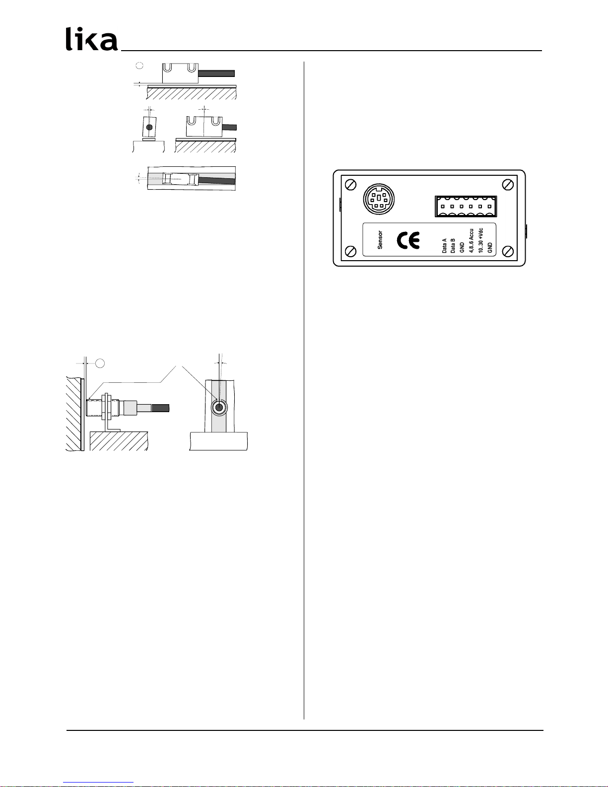
5 - Electrical connections
5.1 SM5 sensor
Plug in the sensor's Mini-DIN connector (circular) on
backside of the display.
5.2 Display
Make the clamp connections as follow:
Serial interface is option.
The ACCU input can supply the device in stand-by
mode with a low consumption. In this way the LED’s
are deactivate while the electronics count and the
sensor remain active.
NOTE:
This device is to be supplied by a Class 2 Circuit or
Low-Voltage Limited Energy or Energy Source not
exceeding 30Vdc.
MAN LD120 I_E 1.5 Pag. 10 www.lika.it
www.lika.biz
D
< 1 °
< 3 ° < 3 °
<3°
D
Marker
PH SYSTEMS - www.phsystems.be - sales@phsystems.be
Page 3

LD120
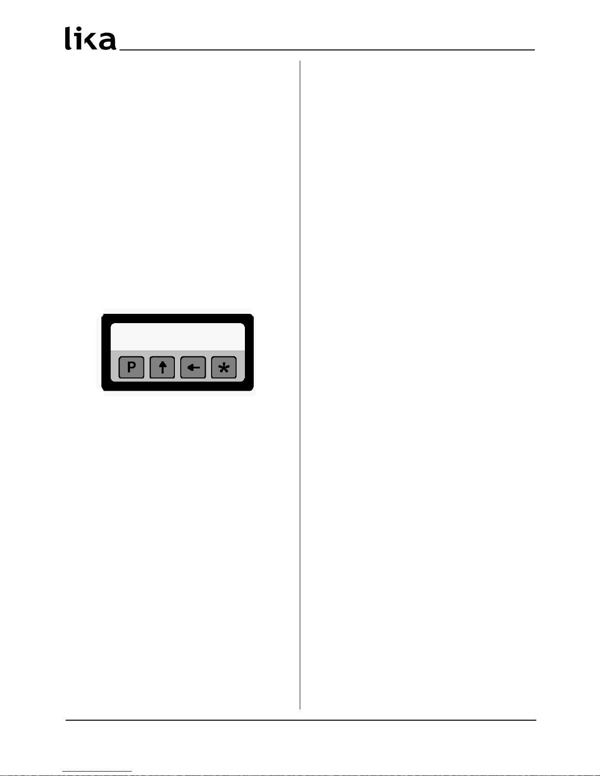
6 - Setup
6.1 Key's function
: UP (select value)
: Shift links (select digit)
* : Save (save data)
P : Program (programming/change parameter)
6.2 Key combinations / Quick functions
6.2.1 Set datum (reference)
Push * key for 3 s to set actual value to datum
value.
Datum value is = rEF + OFS1 + OFSx (where OFSx is
the actually set Offset value).
This function is enabled only if “F_rSt” parameter is
set “on”.
6.2.2 Incremental measurement
Push P and * key simultaneously to switch from
absolute measurement to incremental.
In incremental mode the decimal point flashes.
Zero setting in incremental mode (see 6.2.1) does
not change absolute value in the background.
6.2.3 Mm/inch display modes
Mm/ich display modus can be changed by pushing
key for 3 s.
6.2.4 Offset value modification
Push P and keys simultaneously to display Offset
1 value (OFS1). Use and keys to change value
and save with * key. Further Offset values OFS2 and
OFS3 can be changed only in setup menu.
This function is enable only if “F_oFS” parameter is
set “on”.
key allows to scroll OFS1, OFS2 and OFS3 values.
OFS1 = actual value + OFS1 + rEF
OFS2 = actual value + OFS1 + OFS2 + rEF
OFS3 = actual value + OFS1 + OFS3 + rEF
6.2.5 Datum modification
Push P and keys simultaneously to display datum
value rEF. Use and keys to change value and
save with * key.
This function is enabled only if “F_rEF” parameter is
set “on”.
6.3 Setup / Parameter setting
Push P key for 3 s to enter setup and “SEtUP” is
displayed.
Push key to enter Menu 1 (parameters)
Push * key to enter Menu 2 (RS485 serial I/F)
Push P key to access the next Parameter and
Parameter setting.
Push P key for 3 s to exit the setup at any point.
6.3.1 Default parameters (factory settings)
Default parameter values are written in BOLD
characters. The unit can be reset to default values by
pushing * key while switching on.
6.3.2 Menu 1: Parameters
rES Resolution [10, 50, 100, 1000, InCH, FrEE]
Linear resolution value expressed in µm (microns).
10 = 0,01 mm
50 = 0,05 mm
100 = 0,1 mm
1000 = 1 mm
InCH = sets display mode and measurement unit to
inch (with 3 decimals, e.g. 1.000).
FrEE = allows to input a free resolution factor e.g.
for angle displays (basis of calculation is max.
resolution 0,01 mm).
* = save, P = next parameter, P for 3 s. = exit
FrEE [0.0001, 1.0000]
Only if rES = FrEE.
E.g. angle display with range from 0° to 90° and 0,1°
resolution on a rotating table with circumference of
785,4 mm. Total working range is 785,4 mm : 4 =
196.35 mm.
FrEE = 900 : 19635 = 0,0458
Default value = 0.0001
* = save, P = next parameter, P for 3 s. = exit
dEC Decimal point [0, 1, 2, 3]
Only if rES = FrEE.
Modification of decimal point position.
0 = no decimal point
1 = one decimal (e.g. 1,0)
2 = two decimals (e.g. 1,00)
3 = three decimals (e.g. 1,000)
* = save, P = next parameter, P for 3 s. = exit
MAN LD120 I_E 1.5 Pag. 11 www.lika.it
www.lika.biz
PH SYSTEMS - www.phsystems.be - sales@phsystems.be
Page 4

LD120
dir Counting direction [uP, dn]
uP = up (standard direction)
dn = down (inverted direction)
* = save, P = next parameter, P for 3 s. = exit
F_rEL Incremental measurement function [on, oFF]
Enables incremental measurement function (by
pushing P and * keys).
on = function on
oFF = function off
* = save, P = next parameter, P for 3 s. = exit
F_rSt Datum function [on, oFF]
Enables datum function (by pushing * key).
on = function on
oFF = function off
* = save, P = next parameter, P for 3 s. = exit
F_oFS Offset function [on, oFF]
Enables offset function (by pushing P and keys).
on = function on
oFF = function off
* = save, P = next parameter, P for 3 s. = exit
rEF Datum value [-99999, 99999]
Absolute reference value for the measuring system.
This value is displayed by pushing * key for 3 s.
(displayed value includes previously set offset
values).
Default value = 0
* = save, P = next parameter, P for 3 s. = exit
OFS1 Offset1 value (-99999, 99999)
First offset value (e.g. tool correction). This value is
added to actual value (see 6.2.3.)
Default value = 0
* = save, P = next parameter, P for 3 s. = exit
OFS2 Offset2 value [-99999, 99999]
Second Offset value. This value is added to actual
value and OFS1.
Default value = 0
* = save, P = next parameter, P for 3 s. = exit
OFS3 Offset3 value [-99999, 99999]
Third Offset value. This value is added to actual
value and OFS1.
Default value = 0
* = save, P = next parameter, P for 3 s. = exit
NOTE:
To set negative values, select sign digit with key
and change with key. If “-” sign flashes negative
value is selected, otherwise positive value is
selected. Push * key to save.
F_SAP Save actual value [on, oFF]
Saves the last displayed value after power off.
on = last value memory on
oFF = last value memory off
* = save, P = next parameter, P for 3 s. = exit
When the setup is completed the display shows
"rESEt".
• Push P key to display rEF+OFS1+OFSx
• Push * key to reset the display.
• Push P key twice to quit the setup.
6.3.3 Menu 2: RS485
Ad xx Device address [00, 31]
Setting of device address (only if ordered with serial
interface (option I4).
Default value = 0
* = save, P = next parameter
H_cnt Hourmeter (1/10 h)
Elapsed time indication (display connected to power
supply). Resolution is 1/10 hour (6 minutes).
= hourmeter reset, P = exit
MAN LD120 I_E 1.5 Pag. 12 www.lika.it
www.lika.biz
PH SYSTEMS - www.phsystems.be - sales@phsystems.be
Page 5

LD120
7 - RS485 serial interface (option I4)
If the display is provided with RS485 serial interface,
the following commands can be used.
7.1 RS485 parameters
Baud rate = 9600
Data bits = 8
Parity bit = No
Stop bit = 1
Flow control = Xon/Xoff
7.2 Serial commands
Serial commands must have the following structure:
| A DC M ND = X
where :
| : PC keyboard symbol
AD : device address (00 to 31) 2 digit
CMND : command (see command list)
X : value range (see command list)
Upon receipt of a wrong command the display will
answer with the same command + ? and checksum
(e.g. sent command: |02azs → answer |02azs?EF)
Any common terminal program can be used for
communication with LD120 (e.g. Hyperterminal).
Command will be send after confirmation by ENTER
key (carriage return).
Answers are structured as follow:
ADCMND:SXXXXXCK
where:
AD : device address
CMND : command
XXXXX : value
CK : checksum
The checksum is equal to the least significant byte
of the summing the hex values of all characters
transmitted.
Example:
The displayed position is 8,29. The position of device
with address 01 is read by means of the |01TPOS
command.
The answer is: 01TPOS:+008290F
The sum of hex values of all characters is the
following: 30+31+54+50+4F+53+3A+2B+30+30+
38+ 32+39 = 30F
The least significant byte of 30F is 0F which is the
checksum.
7.2.1 Command list
(below the device address is indicated with AD)
Zeroing of device address
|00RSET
Device address is set to value 0.
Device address [1, 31]
|00INIT=X
Sets device address to value X.
Display device address
|00DADR
Displays device address until P key is pushed.
Change device address [1, 31]
|ADRADR=X
Changes actual device address AD to X.
Answer: ADRADR:+XCHKS (CHKS is checksum and X
is value).
Read actual position
|ADTPOS
Reads actual position of device AD (resolution is
0,01mm).
Change counting direction [0, 1]
|ADRDIR=X
Sets counting direction.
X=0 → uP = standard direction
X=1→ dn = inverted direction
Answer: ADRDIR:+00000XCHKS
Read counting direction
|ADTDIR
Reads the actual counting direction.
X=0→uP , X=1→dn
Answer: ADTDIR:+0000XCHKS
MAN LD120 I_E 1.5 Pag. 13 www.lika.it
www.lika.biz
PH SYSTEMS - www.phsystems.be - sales@phsystems.be
Page 6

LD120
Decimal point [0, 3]
|ADRDEC=X
Modification of decimal point position.
0 = no decimal point
1 = one decimal (e.g. 1,0)
2 = two decimals (e.g. 1,00)
3 = three decimals (e.g. 1,000)
Answer: ADRDEC:+0000XCHKS
ATTENTION: decimal point setting has no influence
on mm/inch display mode (see command |
ADRMMI=0).
Read decimal point position
|ADTDEC
Reads value of actual decimal point position.
X=0→ 0, X=1→ 1, X=2→ 2, X=3→ 3
Answer: ADTDEC:+0000XCHKS
Display mm/inch [0, 1]
|ADRMMI=X
Sets mm or inch display mode.
X=0→ mm
X=1→ inch
Answer: ADRMMI:+0000XCHKS
Read mm/inch display mode
|ADTMMI
Reads value of actual display mode.
X=0→ mm, X=1→ inch
Answer: ADTMMI:+0000XCHKS
Incremental measurement function [0, 1]
Enables incremental measurement function (key
combination P and *).
|ADRRLA=X
X=0→ oFF (function off)
X=1→ on (function on)
Answer: ADRRAE:+0000XCHKS
Read incremental measurement
|ADTRAE
Reads status of incremental measurement function.
X=0→ oFF, X=1→ on
Answer: ADTRAE:+0000XCHKS
Incremental measurement [0, 1]
Sets from absolute display mode to incremental
(relative).
|ADRRLA=X
X=0→ oFF
X=1→ on
Answer: ADRRAE:+0000XCHKS
Read incremental measurement
|ADTRLA
Reads status of absolute/incremental display mode.
X=0→ oFF, X=1→ on
Answer: ADTRLA:+0000XCHKS
Datum function [0, 1]
|ADRRSE=X
Enables datum function (by pushing * key).
X=0→ oFF (function off)
X=1→ on (function on)
Answer: ADRRSE:+0000XCHKS
Read datum function
|ADTRSE
Reads status of datum function.
X=0→ oFF, X=1→ on
Answer: ADTRSE:+0000XCHKS
Datum value modification [0, 1]
|ADRRFE=X
Enables datum value modification (by key
combination P and ).
X=0→ oFF (not enables)
X=1→ on (enabled)
Answer: ADRRFE:+0000XCHKS
Read datum value modification
|ADTRFE
Reads status of datum value modification.
X=0→ oFF, X=1→ on
Answer: ADTRFE:+0000XCHKS
Offset function [0, 1]
|ADROFE=X
Enables offset function (by key combination P and
)
X=0→ oFF (function off)
X=1→ on (function on)
Answer: ADROFE:+0000XCHKS
MAN LD120 I_E 1.5 Pag. 14 www.lika.it
www.lika.biz
PH SYSTEMS - www.phsystems.be - sales@phsystems.be
Page 7

LD120
Read offset function
|ADTOFE
Reads status of offset function.
X=0→ oFF, X=1→ on
Answer: ADTOFE:+0000XCHKS
Resolution [10, 50, 100, 1000]
|ADRRES=X
Sets linear resolution.
X=10→ 0,01 mm
X=50→ 0,05 mm
X=100→ 0,1 mm
X=1000→ 1 mm
Answer: ADRRES:+XCHKS
Read resolution
|ADTRES
Reads value of actual resolution.
X=10→ 0,01 mm, X=50→ 0,05 mm,
X=100→ 0,1 mm, X=1000→ 1 mm
Answer: ADTRES:+XCHKS
Free resolution factor FrEE [0.0001, 1.0000]
|ADRFRE=X
Sets free resolution factor FrEE (see chapter 6.3.2).
Answer: ADRFRE:+XCHKS
Read FrEE factor
|ADTFRE
Reads value of actual FrEE factor.
Answer: ADTFRE:+X.XXXXCHKS
Datum value [-99999, 99999]
|ADRREF=X
Absolute reference value for the measurement
system. Resolution is 0,01.
Answer: ADRREF:XCHKS
Read datum value
|ADTREF
Reads actual datum value.
Answer: ADTREF:XCHKS
Offset1 value [-99999, 99999]
|ADROF1=X
Sets Offset1 (OFSt1) value (resolution 0,01mm).
Answer: ADROF1:XCHKS
Read Offset1 value
|ADTOF1
Reads actual Offset1 value.
Answer: ADTOF1:XCHKS
Offset2 value [-99999, 99999]
|ADROF2=X
Sets Offset2 (OFSt2) value (resolution 0,01mm).
Answer: ADROF2:XCHKS
Read Offset2 value
|ADTOF2
Reads actual Offset2 value.
Answer: ADTOF2:XCHKS
Offset3 value [-99999, 99999]
|ADROF3=X
Sets Offset3 (OFSt3) value (resolution 0,01mm).
Answer: ADROF3:XCHKS
Read Offset3 value
|ADTOF3
Reads actual Offset3 value.
Answer: ADTOF3:XCHKS
Save actual value function [0, 1]
|ADRSPE=X
Saves the last displayed value after power off.
X=0→ oFF
X=1→ on
Answer: ADRSPE:+0000000XCHKS
Read save actual value function
|ADTSPE
Reads status of save actual value function.
X=0→ oFF, X=1→ on
Answer: ADTSPE:+0000000XCHKS
8 - Dimensional drawing and cut-out
8.1 Display Cut-out
Provide a 68 x 33 mm2 (w x h) cut-out.
8.2 SM5 sensor
Check details on product catalogue.
MAN LD120 I_E 1.5 Pag. 15 www.lika.it
www.lika.biz
PH SYSTEMS - www.phsystems.be - sales@phsystems.be
Page 8

LD120
Rev. Man.Vers. Description
0 1.0 1^ issue
1.- SW + Manual update
5 1.5 Chap.6 correction
Lika Electronic
Via S. Lorenzo, 25 - 36010 Carrè (VI) - Italy
Tel. +39 0445 382814
Fax +39 0445 382797
Italy: eMail info@lika.it - www.lika.it
World: eMail info@lika.biz - www.lika.biz
MAN LD120 I_E 1.5 Pag. 16 www.lika.it
www.lika.biz
PH SYSTEMS - www.phsystems.be - sales@phsystems.be
 Loading...