

Page 1

User's guide
ES58, ES58S
EM58, EM58S
ESC58/59/60
EMC58/59/60
Version RS-485
• Singleturn and multiturn absolute rotary encoder
• MODBUS RTU interface (RS-485) with programming software
• Resolution 4,096 cpr (ES58), 4,096 cpr x 16,384 revolutions (EM58)
• Diagnostic LEDs
• IP67 protection rate
Suitable for the following models:
• ES5812/MB-..., ES58S12/MB-...
• ESC5812/MB-..., ESC5912/MB-...,
ESC6012/MB-...
• EM5812/16384MB-..., EM58S12/16384MB-...
• EMC5812/16384MB-...,
EMC5912/16384MB-...,
EMC6012/16384MB-...
Table of Contents
Safety summary 12
Identification 14
Mechanical installation 15
Electrical connections 20
Quick reference 30
MODBUS® interface 50
Programming parameters 65
Programming examples 85
Lika Electronic • Tel. +39 0445 806600 • info@lika.biz • www.lika.biz
Smart encoders & actuators
Page 2

This publication was produced by Lika Electronic s.r.l. 2019. All rights reserved. Tutti i diritti riservati. Alle Rechte vorbehalten. Todos los
derechos reservados. Tous droits réservés.
This document and information contained herein are the property of Lika Electronic s.r.l. and shall not be reproduced in whole or in
part without prior written approval of Lika Electronic s.r.l. Translation, reproduction and total or partial modification (photostat copies,
film and microfilm included and any other means) are forbidden without written authorisation of Lika Electronic s.r.l.
The information herein is subject to change without notice and should not be construed as a commitment by Lika Electronic s.r.l. Lika
Electronic s.r.l. reserves the right to make all modifications at any moments and without forewarning.
This manual is periodically reviewed and revised. As required we suggest checking if a new or updated edition of this document is
available at Lika Electronic s.r.l.'s website. Lika Electronic s.r.l. assumes no responsibility for any errors or omissions in this document.
Critical evaluation of this manual by the user is welcomed. Your comments assist us in preparation of future documentation, in order
to make it as clear and complete as possible. Please send an e-mail to the following address info@lika.it for submitting your
comments, suggestions and criticisms.
Page 3

General contents
User's guide......................................................................................................................................................... 1
General contents............................................................................................................................................. 3
Subject Index................................................................................................................................................... 6
Typographic and iconographic conventions..............................................................................................7
Preliminary information................................................................................................................................ 8
Glossary of MODBUS terms.......................................................................................................................... 9
1 Safety summary.................................................................................................................................. 12
1.1 Safety..............................................................................................................................................................................12
1.2 Electrical safety..........................................................................................................................................................12
1.3 Mechanical safety.....................................................................................................................................................13
2 Identification....................................................................................................................................... 14
3 Mechanical installation..................................................................................................................... 15
3.1 Solid shaft encoders (ES58, ES58S, EM58, EM58S).....................................................................................15
3.1.1 Customary installation................................................................................................................................15
3.1.2 Installation using fixing clamps (code LKM-386)............................................................................16
3.1.3 Installation using a mounting bell (code PF4256)..........................................................................16
3.2 Hollow shaft encoders (ESC58, EMC58, ESC59, EMC59, ESC60, EMC60)..........................................17
3.2.1 ESC58, EMC58.................................................................................................................................................17
3.2.2 ESC59, EMC59.................................................................................................................................................18
3.2.3 ESC60, EMC60.................................................................................................................................................19
4 Electrical connections........................................................................................................................ 20
4.1 CB cable.........................................................................................................................................................................20
4.1.1 CB cable specifications................................................................................................................................20
4.2 M12 5-pin connector...............................................................................................................................................21
4.3 Ground connection...................................................................................................................................................21
4.4 Diagnostic LEDs (Figure 1).....................................................................................................................................22
4.5 DIP switches (Figure 2 and Figure 3).................................................................................................................25
4.5.1 Setting data transmission rate: Baud rate and Parity bit (Figure 3)........................................26
4.5.2 Setting the node address (Figure 3)......................................................................................................27
4.5.3 Termination resistor (Figure 3).................................................................................................................29
5 Quick reference................................................................................................................................... 30
5.1 Getting started...........................................................................................................................................................30
5.2 Configuring the encoder using the software tool by Lika Electronic.................................................31
5.3 Main page of the interface...................................................................................................................................32
5.3.1 Configuring the serial port – Connection to the encoder...........................................................33
Read Params.......................................................................................................................................................35
Write Holding....................................................................................................................................................35
5.3.2 Reading the Input Registers.....................................................................................................................36
Continuous reading.......................................................................................................................................37
Current position...............................................................................................................................................37
Angle.......................................................................................................................................................................37
Counts....................................................................................................................................................................37
Turns.......................................................................................................................................................................37
Baud rate dip switch.....................................................................................................................................37
Address dip switch.........................................................................................................................................38
Page 4

SW version...........................................................................................................................................................38
HW version..........................................................................................................................................................38
Status word.........................................................................................................................................................38
Alarm register....................................................................................................................................................38
Machine data not valid................................................................................................................................38
5.3.3 Reading the exception responses – Exception error......................................................................39
Exception error.................................................................................................................................................39
5.3.4 Reading / writing the Holding Registers.............................................................................................40
Counts per rev...................................................................................................................................................41
Total resolution.................................................................................................................................................41
Preset value.........................................................................................................................................................41
Offset value.........................................................................................................................................................41
Node address......................................................................................................................................................41
Baud rate..............................................................................................................................................................42
Operating parameters...................................................................................................................................42
Enable scaling function...............................................................................................................................42
Change counting dir.....................................................................................................................................42
Control word......................................................................................................................................................42
Enable watchdog...........................................................................................................................................42
Execute preset.................................................................................................................................................43
Upload defaults..............................................................................................................................................43
Auto save..............................................................................................................................................................44
Save parameters.............................................................................................................................................44
5.4 Update FW page - Firmware upgrade..............................................................................................................45
5.4.1 Information on firmware upgrade.........................................................................................................45
5.4.2 Preliminary operations and connections.............................................................................................46
5.4.3 Launching the firmware upgrade process..........................................................................................46
5.5 Manual frame page – Transmitting PDUs manually..................................................................................48
6 MODBUS® interface........................................................................................................................... 50
6.1 MODBUS Master / Slaves protocol principle.................................................................................................50
6.2 MODBUS frame description..................................................................................................................................51
6.3 Transmission modes.................................................................................................................................................52
6.3.1 RTU transmission mode..............................................................................................................................53
6.4 Function codes............................................................................................................................................................55
6.4.1 Implemented function codes...................................................................................................................55
03 Read Holding Registers........................................................................................................................55
04 Read Input Register................................................................................................................................57
06 Write Single Register.............................................................................................................................59
16 Write Multiple Registers......................................................................................................................61
7 Programming parameters................................................................................................................. 65
7.1 Parameters available................................................................................................................................................65
7.1.1 Machine data parameters (Holding registers)...................................................................................65
Custom counts per revolution [0000-0001 hex]............................................................................65
Custom total resolution [0002-0003 hex].........................................................................................67
Preset value [0004-0005 hex]...................................................................................................................70
Offset value [0006-0007 hex]....................................................................................................................71
Operating parameters [0008 hex]...........................................................................................................72
Scaling function...............................................................................................................................................72
Code sequence..................................................................................................................................................73
Control Word [0009 hex]..............................................................................................................................73
Page 5

Watchdog enable............................................................................................................................................74
Save parameters...............................................................................................................................................74
Load default parameters.............................................................................................................................74
Perform counting preset.............................................................................................................................74
7.1.2 Input Register parameters.........................................................................................................................76
Alarms register [0000 hex]..........................................................................................................................76
Machine data not valid................................................................................................................................76
Flash memory error........................................................................................................................................76
Watchdog.............................................................................................................................................................76
Current position [0001-0002 hex]..........................................................................................................77
Register 4 [0003 hex]......................................................................................................................................77
Wrong parameters list [0004-0005 hex]............................................................................................77
DIP switch baud rate [0006 hex]..............................................................................................................78
DIP switch node ID [0007 hex]..................................................................................................................79
SW Version [0008 hex]...................................................................................................................................79
HW Version [0009 hex]..................................................................................................................................79
Status word [000A hex].................................................................................................................................80
Scaling...................................................................................................................................................................80
Counting direction..........................................................................................................................................80
Alarm......................................................................................................................................................................81
7.2 Exception response and codes.............................................................................................................................82
8 Programming examples..................................................................................................................... 85
8.1 Using the 03 Read Holding Registers function code.................................................................................85
8.2 Using the 04 Read Input Register function code........................................................................................86
8.3 Using the 06 Write Single Register function code.....................................................................................87
8.4 Using the 16 Write Multiple Registers function code...............................................................................88
9 Default parameters list...................................................................................................................... 89
9.1 List of the Holding Registers with default value.........................................................................................89
9.2 List of the Input Registers.....................................................................................................................................89
Page 6

Subject Index
A
Address dip switch...........................................................38
Alarm.....................................................................................81
Alarm register....................................................................38
Alarms register [0000 hex]...........................................76
Angle.....................................................................................37
Auto save.............................................................................44
B
Baud rate.............................................................................42
Baud rate dip switch.......................................................37
C
Change counting dir.......................................................42
Code sequence..................................................................73
Continuous reading.........................................................37
Control word......................................................................42
Control Word [0009 hex]..............................................73
Counting direction..........................................................80
Counts...................................................................................37
Counts per rev...................................................................41
Current position................................................................37
Current position [0001-0002 hex]............................77
Custom counts per revolution [0000-0001 hex]65
Custom total resolution [0002-0003 hex]............67
D
DIP switch baud rate [0006 hex]...............................78
DIP switch node ID [0007 hex]...................................79
E
Enable scaling function.................................................42
Enable watchdog..............................................................42
Exception error..................................................................39
Execute preset...................................................................43
F
Flash memory error.........................................................76
H
HW version..........................................................................38
HW Version [0009 hex]..................................................79
L
Load default parameters...............................................74
M
Machine data not valid..........................................38, 76
N
Node address......................................................................41
O
Offset value.........................................................................41
Offset value [0006-0007 hex].....................................71
Operating parameters....................................................42
Operating parameters [0008 hex].............................72
P
Perform counting preset...............................................74
Preset value.........................................................................41
Preset value [0004-0005 hex].....................................70
R
Read Params.......................................................................35
Register 4 [0003 hex].....................................................77
S
Save parameters........................................................44, 74
Scaling..................................................................................80
Scaling function...............................................................72
Status word........................................................................38
Status word [000A hex].................................................80
SW version..........................................................................38
SW Version [0008 hex]...................................................79
T
Total resolution.................................................................41
Turns......................................................................................37
U
Upload defaults.................................................................43
W
Watchdog............................................................................76
Watchdog enable.............................................................74
Write Holding....................................................................35
Wrong parameters list [0004-0005 hex]................77
Page 7

Typographic and iconographic conventions
In this guide, to make it easier to understand and read the text the following typographic and
iconographic conventions are used:
• parameters and objects both of Lika device and interface are coloured in GREEN;
• alarms are coloured in RED;
• states are coloured in FUCSIA.
When scrolling through the text some icons can be found on the side of the page: they are expressly
designed to highlight the parts of the text which are of great interest and significance for the user.
Sometimes they are used to warn against dangers or potential sources of danger arising from the use of
the device. You are advised to follow strictly the instructions given in this guide in order to guarantee the
safety of the user and ensure the performance of the device. In this guide the following symbols are
used:
This icon, followed by the word WARNING, is meant to highlight the parts of the
text where information of great significance for the user can be found: user must
pay the greatest attention to them! Instructions must be followed strictly in order
to guarantee the safety of the user and a correct use of the device. Failure to heed
a warning or comply with instructions could lead to personal injury and/or damage
to the unit or other equipment.
This icon, followed by the word NOTE, is meant to highlight the parts of the text
where important notes needful for a correct and reliable use of the device can be
found. User must pay attention to them! Failure to comply with instructions could
cause the equipment to be set wrongly: hence a faulty and improper working of
the device could be the consequence.
This icon is meant to highlight the parts of the text where suggestions useful for
making it easier to set the device and optimize performance and reliability can be
found. Sometimes this symbol is followed by the word EXAMPLE when instructions
for setting parameters are accompanied by examples to clarify the explanation.
Page 8

Preliminary information
This guide is designed to provide the most complete information the operator needs to correctly and
safely install and operate the ES58 series singleturn and EM58 series multiturn absolute encoders
equipped with MODBUS interface.
They are:
• ES5812/MB-...
• ES58S12/MB-...
• ESC5812/MB-...
• ESC5912/MB-...
• ESC6012/MB-...
• EM5812/16384MB-...
• EM58S12/16384MB-...
• EMC5812/16384MB-...
• EMC5912/16384MB-...
• EMC6012/16384MB-...
For technical specifications please refer to the product datasheet.
To make it easier to read the text, this guide can be divided into two main sections.
In the first section general information concerning the safety, the mechanical installation and the
electrical connection as well as tips for setting up and running properly and efficiently the device are
provided.
In the second section, entitled MODBUS Interface, both general and specific information is given on the
MODBUS interface. In this section the interface features and the registers implemented in the unit are
fully described.
In the “Quick reference” section on page 30 the software tool designed by Lika Electronic to easily
configure the encoder via RS-485 serial port is fully described.
Page 9

Glossary of MODBUS terms
MODBUS, like many other networking systems, has a set of unique terminology. Table below contains a
few of the technical terms used in this guide to describe the MODBUS interface. They are listed in
alphabetical order.
Address field
It contains the Slave address.
Application Process
The Application Process is the task on the Application Layer.
Application protocol
MODBUS is an application protocol or messaging structure
that defines rules for organizing and interpreting data
independent of the data transmission medium.
ASCII transmission mode
When devices are setup to communicate on a MODBUS serial
line using ASCII (American Standard Code for Information
Interchange) mode, each 8–bit byte in a message is sent as
two ASCII characters. This mode is used when the physical
communication link or the capabilities of the device does not
allow the conformance with RTU mode requirements
regarding timers management.
Bus
A bus is a communication medium connecting several nodes.
Data can be transferred via serial or parallel circuits, that is, via
electrical conductors or fibre optic.
Client
A Client is any network device that sends data requests to
servers.
MODBUS follows the Client/Server model. MODBUS Masters
are referred to as Clients, while MODBUS Slaves are Servers.
Cyclic Redundancy Check
(CRC)
Error-checking technique in which the frame recipient
calculates a remainder by dividing frame contents by a prime
binary divisor and compares the calculated remainder to a
value stored in the frame by the sending node.
Data encoding
MODBUS uses a ‘big-Endian’ representation for addresses and
data items. This means that when a numerical quantity larger
than a single byte is transmitted, the most significant byte is
sent first.
Exception code
Code to be returned by Slaves in the event of problems. All
exceptions are signalled by adding 0x80 to the function code
of the request.
Exception response
MODBUS operates according to the common client/server
(Master/Slave) model: the Client (Master) sends a request
telegram (service request) to the Server (Slave), and the Server
replies with a response telegram. If the Server cannot process
a request, it will instead return a error function code
(exception response) that is the original function code plus
80H (i.e. with its most significant bit set to 1).
Function code
MODBUS is a request/reply protocol and offers services
Page 10

specified by function codes. The function code is sent from a
Client to the Server and indicates which kind of action the
Server must perform. MODBUS function codes are elements of
MODBUS request/reply PDUs.
The function code field of a MODBUS data unit is coded in one
byte. Valid codes are in the range of 1 ... 255 decimal (the
range 128 – 255 is reserved and used for exception responses).
Function code "0" is not valid. Lika devices only implement
public function codes.
Holding register
In the MODBUS data model, a Holding register is the output
data. A Holding register has a 16-bit quantity, is alterable by
an application program, and allows either read-write or readonly access.
IEEE 1588
This standard defines a protocol enabling synchronisation of
clocks in distributed networked devices (e.g. connected via
Ethernet).
Input register
In the MODBUS data model, an Input register is the input
data. An Input register has a 16-bit quantity, is provided by an
I/O system, and allows read-only access.
LRC Checking
In ASCII mode, messages include an error–checking field that
is based on a Longitudinal Redundancy Checking (LRC)
calculation that is performed on the message contents,
exclusive of the beginning ‘colon’ and terminating CRLF pair
characters. It is applied regardless of any parity checking
method used for the individual characters of the message.
Master
A Master is any network device that sends data requests to
Slaves.
Message
The MODBUS messaging service provides a Client/Server
communication between devices connected on the network.
The Client / Server model is based on four types of messages:
• MODBUS Request
• MODBUS Confirmation
• MODBUS Indication
• MODBUS Response
The MODBUS messaging services are used for information
exchange.
MODBUS Confirmation
A MODBUS Confirmation is the Response Message received on
the Client side.
MODBUS Indication
A MODBUS Indication is the Request message received on the
Server side.
MODBUS Request
A MODBUS Request is the message sent on the network by the
Client to initiate a transaction.
MODBUS Response
A MODBUS Response is the Response message sent by the
Server.
Network
Network is a group of computers on a single physical network
segment.
Page 11

PDU
The Protocol Data Unit (PDU) is the MODBUS function code
and data field. It is packed together with the Address Field and
the CRC (or LRC) to form the Modbus Serial Line PDU.
The MODBUS protocol defines three PDUs. They are:
• MODBUS Request PDU, mb_req_pdu
• MODBUS Response PDU, mb_rsp_pdu
• MODBUS Exception Response PDU,
mb_excep_rsp_pdu
Read Holding Registers
(03, 0003hex)
This function code is used to READ the contents of a
contiguous block of holding registers in a remote device; in
other words, it allows to read the values set ina group of work
parameters placed in order.
Read Input Register (04,
0004hex)
This function code is used to READ from 1 to 125 contiguous
input registers in a remote device; in other words, it allows to
read some result values and state / alarm messages in a
remote device.
Register
MODBUS functions operate on memory registers to configure,
monitor, and control device I/O.
RTU transmission mode
Remote Terminal Unit. When devices communicate on a
MODBUS serial line using the RTU mode, each 8–bit byte in a
message contains two 4–bit hexadecimal characters. The main
advantage of this mode is that its greater character density
allows better data throughput than ASCII mode for the same
baud rate. Each message must be transmitted in a continuous
stream of characters.
Server
A Server is any program that awaits data requests to be sent
to it. Servers do no initiate contacts with Clients, but only
respond to them.
MODBUS follows the Client/Server model. MODBUS Masters
are referred to as clients, while MODBUS Slaves are servers.
Service request
It is the MODBUS Request, i.e. the message sent on the
network by the Client to initiate a transaction.
Slave
A Slave is any program that awaits data requests to be sent to
it. Slaves do no initiate contacts with Masters, but only
respond to them.
Transmission rate
Data transfer rate (in bps).
Write Multiple Registers
(16, 0010hex)
This function code is used to WRITE a block of contiguous
registers (1 to 123 registers) in a remote device.
Write Single Register (06,
0006hex)
This function code is used to WRITE a single holding register in
a remote device.
Page 12

ES58 • EM58 MODBUS®
1 Safety summary
1.1 Safety
• Always adhere to the professional safety and accident prevention
regulations applicable to your country during device installation and
operation;
• installation and maintenance operations have to be carried out by
qualified personnel only, with power supply disconnected and stationary
mechanical parts;
• device must be used only for the purpose appropriate to its design: use for
purposes other than those for which it has been designed could result in
serious personal and/or the environment damage;
• high current, voltage and moving mechanical parts can cause serious or
fatal injury;
• warning ! Do not use in explosive or flammable areas;
• failure to comply with these precautions or with specific warnings
elsewhere in this manual violates safety standards of design, manufacture,
and intended use of the equipment;
• Lika Electronic assumes no liability for the customer's failure to comply
with these requirements.
1.2 Electrical safety
• Turn OFF the power supply before connecting the device;
• connect according to the explanation in the ”Electrical connections”
section on page 20;
• in compliance with 2014/30/EU norm on electromagnetic
compatibility, following precautions must be taken:
- before handling and installing the equipment, discharge
electrical charge from your body and tools which may come in touch
with the device;
- power supply must be stabilized without noise; install EMC filters on
device power supply if needed;
- always use shielded cables (twisted pair cables whenever possible);
- avoid cables runs longer than necessary;
- avoid running the signal cable near high voltage power cables;
- mount the device as far as possible from any capacitive or inductive
noise source; shield the device from noise source if needed;
- to guarantee a correct working of the device, avoid using strong magnets
on or near by the unit;
MAN ESx58x_EMx58x MB E 1.2 Safety summary 12 of 92
Page 13

ES58 • EM58 MODBUS®
- minimize noise by connecting the shield and/or the connector housing
and/or the frame to ground. Make sure that ground is not affected by
noise. The connection point to ground can be situated both on the device
side and on user’s side. The best solution to minimize the interference
must be carried out by the user.
1.3 Mechanical safety
• Install the device following strictly the information in the “Mechanical
installation” section on page 15;
• mechanical installation has to be carried out with stationary mechanical
parts;
• do not disassemble the unit;
• do not tool the unit or its shaft;
• delicate electronic equipment: handle with care; do not subject the device
and the shaft to knocks or shocks;
• respect the environmental characteristics of the product;
• unit with solid shaft: in order to guarantee maximum reliability over time
of mechanical parts, we recommend a flexible coupling to be installed to
connect the encoder and user's shaft; make sure the misalignment
tolerances of the flexible coupling are respected;
• unit with hollow shaft: the encoder can be mounted directly on a shaft
whose diameter has to respect the technical characteristics specified in the
purchase order and clamped by means of the collar and, when requested,
the anti-rotation pin.
MAN ESx58x_EMx58x MB E 1.2 Safety summary 13 of 92
Page 14

ES58 • EM58 MODBUS®
2 Identification
The device can be identified through the order code and the serial number
printed on the label applied to its enclosure. Information is listed in the delivery
document too. Please always quote the order code and the serial number when
reaching Lika Electronic for purchasing spare parts or needing assistance. For
any information on the technical characteristics of the product refer to the
technical catalogue.
Warning: devices having order code ending with "/Sxxx" may have
mechanical and electrical characteristics different from standard and
be supplied with additional documentation for special connections
(Technical Info).
MAN ESx58x_EMx58x MB E 1.2 Identification 14 of 92
Page 15

ES58 • EM58 MODBUS®
3 Mechanical installation
WARNING
Installation and maintenance operations must be carried out by qualified
personnel only, with power supply disconnected. Shaft and mechanical
components must be in stop.
For any information on the mechanical data and the electrical characteristics of
the encoder please refer to the technical catalogue.
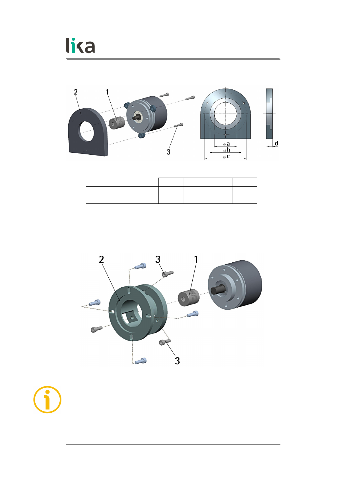
3.1 Solid shaft encoders (ES58, ES58S, EM58, EM58S)
• Mount the flexible coupling 1 on the encoder shaft;
• fix the encoder to the flange 2 (or to the mounting bell) by means of the
screws 3;
• secure the flange 2 to the support (or the mounting bell to the motor);
• mount the flexible coupling 1 on the motor shaft;
• make sure to comply with the misalignment tolerances of the flexible
coupling 1.
3.1.1 Customary installation
a [mm] b [mm] c [mm] d [mm]
ES58, EM58
- 42 50 F7 4
ES58S, EM58S
36 H7 48 - -
MAN ESx58x_EMx58x MB E 1.2 Mechanical installation 15 of 92
Page 16
ES58 • EM58 MODBUS®
3.1.2 Installation using fixing clamps (code LKM-386)
a [mm] b [mm] c [mm] d [mm]
ES58, EM58
- 50 F7 67 4
ES58S, EM58S
36 H7 - 67 -
3.1.3 Installation using a mounting bell (code PF4256) ES58S, EM58S
NOTE
In order to guarantee reliability over time of the encoder mechanical parts, we
recommend a flexible coupling to be installed between the encoder and the
motor shaft. Make sure to comply with the misalignment tolerances of the
flexible coupling.
MAN ESx58x_EMx58x MB E 1.2 Mechanical installation 16 of 92
Page 17

ES58 • EM58 MODBUS®
3.2 Hollow shaft encoders (ESC58, EMC58, ESC59, EMC59, ESC60, EMC60)
3.2.1 ESC58, EMC58
• Fasten the anti-rotation pin 1 to the rear of the motor (secure it using a
locknut);
• mount the encoder on the motor shaft using the reducing sleeve 8 (if
supplied). Avoid forcing the encoder shaft;
• insert the anti-rotation pin 1 into the slot on the flange of the encoder; this
secures it in place by grub screw 2, preset at Lika;
• fix the collar 3 to the encoder shaft (apply threadlocker to screw 3).
MAN ESx58x_EMx58x MB E 1.2 Mechanical installation 17 of 92
Page 18

ES58 • EM58 MODBUS®
3.2.2 ESC59, EMC59
• Mount the encoder on the motor shaft using the reducing sleeve 8 (if
supplied). Avoid forcing the encoder shaft;
• fasten the fixing plate 4 to the rear of the motor using two M3 cylindrical
head screws 5;
• fix the collar 3 to the encoder shaft (apply threadlocker to screw 3).
MAN ESx58x_EMx58x MB E 1.2 Mechanical installation 18 of 92
Page 19
ES58 • EM58 MODBUS®
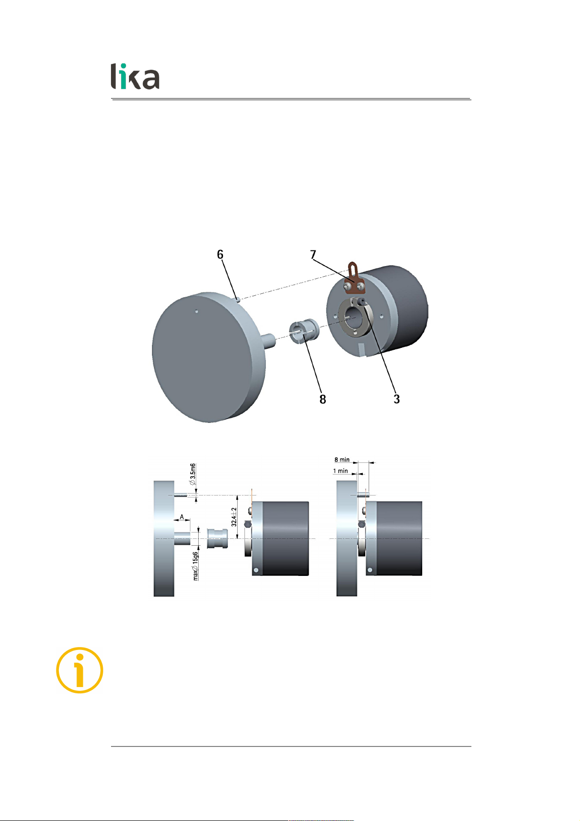
3.2.3 ESC60, EMC60
• Fix the tempered pin 6 to the rear of the motor;
• mount the encoder on the motor shaft using the reducing sleeve 8 (if
supplied). Avoid forcing the encoder shaft;
• make sure the anti-rotation pin 6 is inserted properly into the fixing plate 7;
• fix the collar 3 to the encoder shaft (apply threadlocker to screw 3).
NOTE
You are strongly advised not to carry out any mechanical operations (drilling,
milling, etc.) on the encoder shaft. This could cause serious damages to the
internal parts and an immediate warranty loss. Please contact our technical
personnel for the complete availability of "custom made" shafts.
MAN ESx58x_EMx58x MB E 1.2 Mechanical installation 19 of 92
Page 20

ES58 • EM58 MODBUS®
4 Electrical connections
WARNING
Electrical connections must be carried out by qualified personnel only, with
power supply disconnected. Shaft and mechanical components must be in stop.
For any information on the mechanical data and the electrical characteristics of
the encoder please refer to the technical catalogue.
4.1 CB cable
Colour Description
Red
+10Vdc +30Vdc
power supply voltage
Black
1
0Vdc
power supply voltage
White Modbus A (RS-485)
Blue Modbus B (RS-485)
1 0Vdc of the RS-485 serial connection too.
4.1.1 CB cable specifications
Model : LIKA CB type cable
Wires : 2 x 0.24 mm2 (24/19AWG) + 2 x 0.35 mm
2
(22/19AWG) pair cable
Jacket : PUR flame retardant and halogen free
Shield : tinned copper wire braid 65% nom. coverage
External diameter : 6.9 mm ±0.2 (0.272” ±0.008”)
Min. bend radius : external Ø x 6 (fixed); external Ø x 12 (dynamic)
Operating temperature : -40°C +80°C / -40°F +185°F (fixed); -30°C +70°C /
-22°F +158°F (dynamic)
Max. conductor resistance: 78.0 /km (24AWG) / 54.0 /km (22AWG)
Max. translation speed : 3.0 m/sec
Max. acceleration : 5.0 m/sec
2
MAN ESx58x_EMx58x MB E 1.2 Electrical connections 20 of 92
Page 21

ES58 • EM58 MODBUS®
4.2 M12 5-pin connector
M12 5-pin
male connector
A coding
(frontal view)
Pin Description
1
1
Shielding
2
+10Vdc +30Vdc
power supply voltage
3
2
0Vdc
power supply voltage
4 Modbus A (RS-485)
5 Modbus B (RS-485)
Case
3
Shielding
1 Pin 1 is intended to allow the connection of the shield to
ground even if the plug connector has a plastic case.
2 OVdc of the RS-485 serial connection too.
3 Lika's EC- pre-assembled cables only
4.3 Ground connection
To minimize noise connect properly the shield and/or the connector housing
and/or the frame to ground. Connect properly the cable shield to ground on
user's side. Lika's EC- pre-assembled cables are fitted with shield connection to
the connector ring nut in order to allow grounding through the body of the
device. Lika's E- connectors have a plastic gland, thus grounding is not possible.
In the specific case pin 1 of M12 connector is specifically intended to allow the
connection of the shield to ground. If metal connectors are used, connect the
cable shield properly as recommended by the manufacturer. Anyway make sure
that ground is not affected by noise. It is recommended to provide the ground
connection as close as possible to the device.
MAN ESx58x_EMx58x MB E 1.2 Electrical connections 21 of 92
Page 22

ES58 • EM58 MODBUS®
4.4 Diagnostic LEDs (Figure 1)
Figure 1: Diagnostic LEDs
Two bicoloured LEDs located in the rear side of the encoder (see the Figure here
above) are meant to show visually the operating or fault status of the MODBUS
MAN ESx58x_EMx58x MB E 1.2 Electrical connections 22 of 92
Page 23

ES58 • EM58 MODBUS®
interface and the device as well. The meaning of each LED is explained in the
following table. In case of error, to know in detail which alarm has been
triggered, see the Alarms register [0000 hex] variable on page 76.
ACTIVITY LED Description
Blinking GREEN
Indicates the device is sending or receiving a
message.
OFF Indicates there is no send - receive activity.
STATUS/ERROR LED Description
ON GREEN
No active alarm.
Blinking RED
Indicates there are either active alarms or an
internal error. For further information refer to
Alarms register [0000 hex] on page 76.
ON RED
An hardware error has occurred which
prevents the unit from continuing to run.
Please turn the device off and then on again.
If the error is still on, please contact Lika
Electronic After Sales Service.
While performing the firmware upgrade operation (bootloading, refer to the “5.4
Update FW page - Firmware upgrade” section on page 45), the two LEDs operate
in a specific way, as explained in the following table.
ACTIVITY
LED
STATUS/ERROR
LED
Description
Blinking
GREEN at 5 Hz
with duty cycle
= 50%
Blinking
GREEN at 5 Hz
with duty cycle
= 50%
While downloading data to the flash memory
for upgrading the firmware of the unit (see
the “5.4 Update FW page - Firmware
upgrade” section on page 45), both LEDs blink
green at 5 Hz with duty cycle = 50%.
Blinking
RED at 2 Hz with
duty cycle =
50%
Blinking
RED at 2 Hz with
duty cycle =
50%
The operator has pressed the BOOT STATE
button in the Firmware Upgrade page, the
encoder is waiting for the firmware upgrade
operation to start (by pressing the
DOWNLOAD button). For any information
please refer to the “5.4 Update FW page -
Firmware upgrade” section on page 45.
MAN ESx58x_EMx58x MB E 1.2 Electrical connections 23 of 92
Page 24

ES58 • EM58 MODBUS®
ACTIVITY
LED
STATUS/ERROR
LED
Description
Blinking
RED at 5 Hz with
duty cycle =
50%
Blinking
RED at 5 Hz with
duty cycle =
50%
While downloading data to the flash memory
for upgrading the firmware of the unit (see
the “5.4 Update FW page - Firmware
upgrade” section on page 45), if an error
occurs which stops the upgrading process
(for instance: a voltage drop and/or the
switching off of the unit), as soon as the
power is turned on again both LEDs start
blinking red at 5 Hz with duty cycle = 50% as
the user program is not installed in the flash
memory (it has been deleted previously). For
any information on restoring the unit please
refer to the “5.4 Update FW page - Firmware
upgrade” section on page 45.
ON
RED
ON
RED
While downloading data to the flash memory
for upgrading the firmware of the unit (see
the “5.4 Update FW page - Firmware
upgrade” section on page 45), if data
transmission is cut off (for instance, because
of the disconnection of the serial cable), after
5 seconds both LEDs come on solidly red. For
any information on restoring the unit please
refer to the “5.4 Update FW page - Firmware
upgrade” section on page 45.
OFF
ON GREEN
The firmware upgrade operation has been
carried out successfully, the encoder is
operating properly and no error is active. For
any information please refer to the “5.4
Update FW page - Firmware upgrade” section
on page 45.
During initialisation, system checks the diagnostic LEDs for proper operation;
therefore they blink for a while.
MAN ESx58x_EMx58x MB E 1.2 Electrical connections 24 of 92
Page 25

ES58 • EM58 MODBUS®
4.5 DIP switches (Figure 2 and Figure 3)
WARNING
Power supply must be turned off before performing this operation!
NOTE
When performing this operation be careful not to damage the internal
components and the connection wires.
To access the DIP switches loosen and remove the M12 metal screw plug in the
rear of the encoder. Be careful to replace the screw plug at the end of the
operation.
Figure 2: Reaching the DIP switches
MAN ESx58x_EMx58x MB E 1.2 Electrical connections 25 of 92
Page 26
ES58 • EM58 MODBUS®
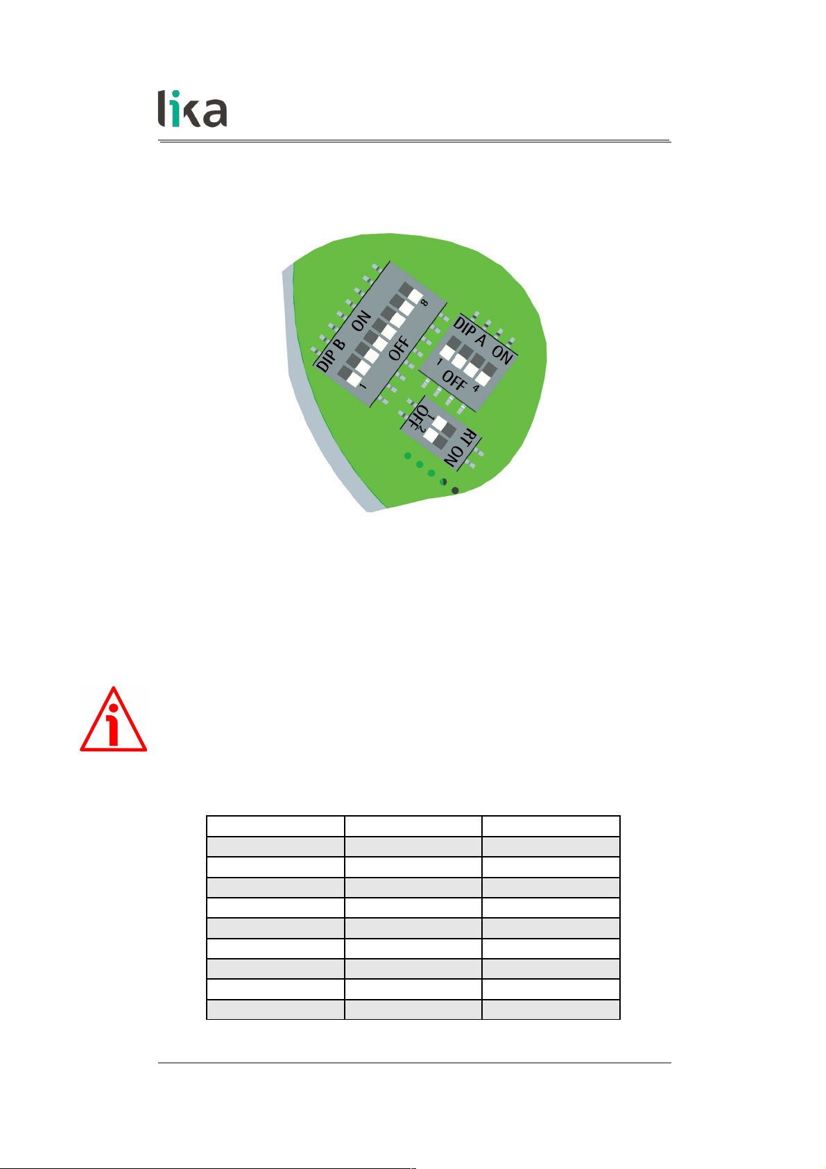
The DIP switches are located just beneath.
Figure 3: DIP switches
4.5.1 Setting data transmission rate: Baud rate and Parity bit (Figure 3)
WARNING
Power supply must be turned off before performing this operation!
Use the DIP switch A to set the data transmission rate (baud rate and parity bit).
Set the binary value of the baud rate and the parity bit according to the
following table, considering that: ON = 1; OFF = 0.
Switch Baud rate Parity bit
0000 9600 bit/s No parity
1000 9600 bit/s Even
0100 9600 bit/s Odd
1100 19200 bit/s No parity
0010 (default) 19200 bit/s Even
1010 19200 bit/s Odd
0110 115200 bit/s No parity
1110 115200 bit/s Even
0001 115200 bit/s Odd
MAN ESx58x_EMx58x MB E 1.2 Electrical connections 26 of 92
Page 27
ES58 • EM58 MODBUS®
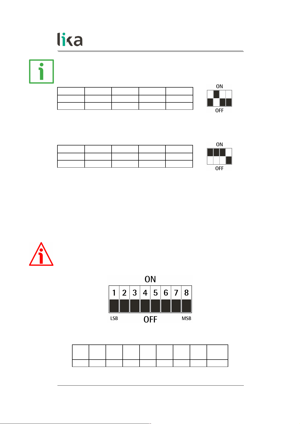
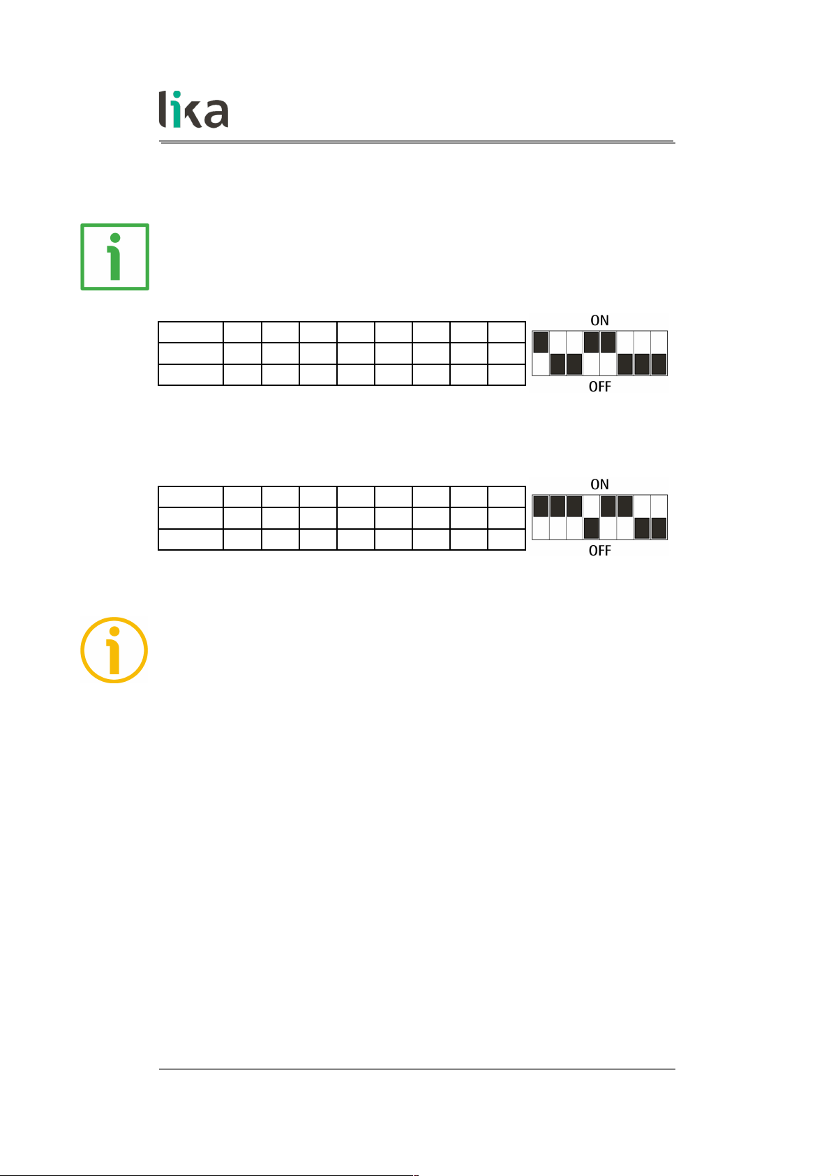
EXAMPLE
Set the baud rate to 9600 bits per second and Odd parity bit:
Switches 1 2 3 4
Position OFF ON OFF OFF
Value 0 1 0 0
Set the baud rate to 115200 bits per second and Even parity bit:
Switches 1 2 3 4
Position ON ON ON OFF
Value 1 1 1 0
The data transmission rate which is currently set in the unit can be read next to
the DIP switch baud rate [0006 hex] register, see on page 78.
4.5.2 Setting the node address (Figure 3)
WARNING
Power supply must be turned off before performing this operation!
Use the DIP switch B to set the node address.
Set the binary value of the node address, considering that: ON = 1; OFF = 0.
bit
1
LSB
2 3 4 5 6 7
8
MSB
2
0
2
1
2
2
2
3
2
4
2
5
2
6
2
7
MAN ESx58x_EMx58x MB E 1.2 Electrical connections 27 of 92
Page 28
ES58 • EM58 MODBUS®
The range of node addresses is between 1 and 247. The default address is 1.
EXAMPLE
Set the node address to 25:
2510 = 0001 10012 (binary value)
Switches 1 2 3 4 5 6 7 8
Position
ON OFF OFF ON ON OFF OFF OFF
Value
1 0 0 1 1 0 0 0
Set the node address to 55:
5510 = 0011 01112 (binary value)
Switches 1 2 3 4 5 6 7 8
Position
ON ON ON OFF ON ON OFF OFF
Value
1 1 1 0 1 1 0 0
NOTE
The default address is 1.
The address 0 is reserved to identify a “broadcast” exchange (Master sends a
request to all Slaves connected to the Modbus network). See the “6.1 MODBUS
Master / Slaves protocol principle” section on page 50.
The Modbus Master node has no specific address, only the Slave nodes must
have an address. Each Slave must have a unique address.
Addresses from 248 to 255 are reserved.
If you set the address 0, device will be set to 1 automatically.
If you set an address that is greater than 247, the device will be set to 247
automatically.
The node address which is currently set in the unit can be read next to the DIP
switch node ID [0007 hex] register, see on page 79.
MAN ESx58x_EMx58x MB E 1.2 Electrical connections 28 of 92
Page 29

ES58 • EM58 MODBUS®
4.5.3 Termination resistor (Figure 3)
WARNING
Power supply must be turned off before performing this operation!
Use the RT DIP switch to activate or deactivate the bus termination. The bus
termination resistor must be activated as line termination in the first or the last
device of the transmission line (both at the beginning and the end of the
communication bus).
RT Description
1 = 2 = ON
Activated: when the device is either the first
or the last of the transmission line
1 = 2 = OFF
Deactivated: when the device is neither the
first nor the last of the transmission line
MAN ESx58x_EMx58x MB E 1.2 Electrical connections 29 of 92
Page 30

ES58 • EM58 MODBUS®
5 Quick reference
5.1 Getting started
The following instructions are given to allow the operator to set up the device
for standard operation in a quick and safe mode.
• Mechanically install the device, see on page 15 ff;
• execute electrical connections, see on page 20 ff;
• set the data transmission rate (baud rate and parity bit; see the “4.5.1
Setting data transmission rate: Baud rate and Parity bit (Figure 3)” section
on page 26); the default value set by Lika Electronic at factory set-up is
“baud rate = 19200 bit/s, parity = Even”;
• set the node address (node ID; see the “4.5.2 Setting the node address
(Figure 3)” section on page 27); the default value set by Lika Electronic at
factory set-up is “1”;
• switch +10Vdc ÷ +30Vdc power supply on;
• if you want to use the physical resolution of the device (ES58: singleturn
physical resolution = 4,096 cpr; number of physical revolutions = 1
revolution; total physical resolution = 4,096 counts; 12 bits; EM58:
singleturn physical resolution = 4,096 cpr; number of physical revolutions
= 16,384 revolutions; total physical resolution = 67,108,864 counts; 26
bits), please check that the Scaling function item is disabled (bit 0 in the
Operating parameters [0008 hex] register = 0; see on page 72);
• otherwise if you need a specific resolution, please enable the Scaling
function item (bit 0 in the Operating parameters [0008 hex] register =
1; see on page 72);
• then set the value you need for the singleturn resolution next to the
Custom counts per revolution [0000-0001 hex] item (registers 1 and
2; see on page 65);
• set the value you need for the overall resolution next to the Custom total
resolution [0002-0003 hex] item (registers 3 and 4; see on page 67);
• now, if you need you can set the Preset next to the Preset value [0004-
0005 hex] register and then execute the Perform counting preset
command bit 11 in the Control Word [0009 hex] register; see on page
70);
• finally save the new setting values (Save parameters command bit 9 in
the Control Word [0009 hex] register; see on page 74).
MAN ESx58x_EMx58x MB E 1.2 Quick reference 30 of 92
Page 31

ES58 • EM58 MODBUS®
5.2 Configuring the encoder using the software tool by Lika Electronic
ES58 / EM58 series rotary encoders with MODBUS interface are supplied with a
software expressly developed by Lika Electronic in order to easily programme
and configure the devices. It allows the operator to set the working parameters
of the device and monitor whether the devices are running properly. The
program is supplied for free and can be installed in any PC fitted with a
Windows operating system (Windows XP or later). The name of the program
executable file is MODBUS-RTU.EXE, it is available for download through the
SOFTWARE link in the page of the website dedicated to the devices. The program
is designed to be installed simply by copying the executable file to the desired
location and no installation process is required. To launch the program just
double-click the file icon. To close the program press the CLOSE button at the
top right of the window.
NOTE
Please note that the program is designed to interface several encoder models
equipped with MODBUS interface. When you open the page of the interface,
before trying to establish the serial connection, it is necessary to select the
model of the connected encoder among the ones in the list.
NOTE
Before starting the program and establishing a communication with the device,
it is necessary to connect it to the personal computer. The interface of the
ES58 / EM58 series encoders is a serial RS-485 type, the standard of the serial
port in the personal computer (when the port is available) is the RS-232 type.
Therefore you must install an RS-232 to RS-485 converter, easily available in the
market. Should the personal computer not be equipped with a serial port (RS232 or RS-485), you must install a USB to RS-485 converter, easily available in
the market too. For complete information on the connection scheme and the
cable pinout refer to the instruction sheet provided with the converter.
On the ENCODER side the cable must be connected as described in the
“Electrical connections” section on page 20. Always be sure that RX wire in the
MODBUS ENCODER is connected up to TX wire in the PC and RX wire in the PC
is connected up to TX wire in the MODBUS ENCODER.
An optional kit fitted with RS-485/USB adapter for the communication between
the encoder and the PC is available for M12 output.
The order code is as follows:
• KIT EM58 MB M12 / USB adapter cable.
MAN ESx58x_EMx58x MB E 1.2 Quick reference 31 of 92
Page 32

ES58 • EM58 MODBUS®
5.3 Main page of the interface
To launch the program and configure the MODBUS encoder double-click the
MODBUS-RTU.EXE executable file.
The interface consists of a main page and two subpages.
When the program starts, the main page will appear on the screen.
The main page of the interface can be divided into seven parts.
1. In the first SERIAL LINE group box on the top left of the page the items
necessary to select the serial port and connect to the device are
available.
2. In the DEVICE group box on the top centre of the page the items
necessary to select the node address and the commands needful for
starting the connection process and, once the connection is established,
for reading and writing the parameters are available.
3. In the group box on the further right some information on the
connected encoder are displayed (after the connection is established).
4. In the FUNCTIONS group box on the top right of the page you can find
the commands to enter the main page, the page for firmware upgrade
and the page that allows to send Request PDUs manually.
5. In the INPUT REGISTERS group box on the bottom left of the page the
Input registers are available, they provide result values and status /
alarm information on the device. These items are described in the “7.1.2
Input Register parameters” section on page 76.
MAN ESx58x_EMx58x MB E 1.2 Quick reference 32 of 92
Page 33

ES58 • EM58 MODBUS®
6. In the EXCEPTION ERROR group box just beneath, the exception
response messages are shown, the Server transmits exception responses
to the Client when an error occurs because the Server is not able to
handle the request from the Client. For more information on the
exception responses and the MODBUS exception codes please refer to
the “7.2 Exception response and codes“ section on page 82.
7. In the HOLDING REGISTERS group box on the bottom right of the page
the Holding Registers are available; the items in this area allow to read
in or write into the working parameters of the connected device.
The main page allows the operator to choose the language used to display texts
and items in the user interface. Click the Italian flag icon at the top
right of the page to choose the Italian language; click the UK flag icon
to choose the English language.
On the top right of the page over the FUNCTIONS group box the MESSAGES >
button is available. By pressing the button the main page widens and a window
appears on the right: it shows the frames that are exchanged between the
software tool and the device. To close the messages window and display back
the main page only, press the < CLOSE button.
5.3.1 Configuring the serial port – Connection to the encoder
The first four group boxes at the top of the main page are used to connect to
the device via serial port. In particular they allow (in order):
• to select the serial port of the pc the encoder is connected to (SERIAL
LINE group box);
• to set the node address of the connected device and start the scanning
operation for finding the connected device (DEVICE group box);
• to show information about the connected device, once the connection is
carried out properly (group box between DEVICE and FUNCTIONS);
• to choose the page to be displayed (FUNCTIONS group box).
MAN ESx58x_EMx58x MB E 1.2 Quick reference 33 of 92
Page 34

ES58 • EM58 MODBUS®
When the page of the interface opens, by means of the drop-down box in the
Select serial com drop-down box of the SERIAL LINE group box you can
choose the serial port the device is connected to. The port that is currently
selected is indicated in the drop-down box. If you do not know the number of
the COM port the device is connected to, select the All coms check box.
In the Address item of the DEVICE group box the MODBUS address of the
connected device must be entered. By default the address of all Lika devices is
“1”. If you do not know the MODBUS address of the networked device select the
All addresses check box.
If you select the All coms check box and the All addresses check box the tool
will scan all the available serial ports (COM1 first, then COM2, COM3, etc., if
installed) and will test for each one all the baud rate and parity bit options
(9600 No parity, 9600 Even, 9600 Odd, etc.) and all the possible addresses (from
1 to 247, according to the MODBUS protocol).
It is clear that this searching operation may take a while.
To start searching and connect to the device press the CONNECT button in the
DEVICE group box. While the program is attempting to connect to the device, a
green progress bar and the Busy label over the Select serial com drop-down
box indicate that the port is currently open and being checked. As long as the
communication is active the bar indicates that the port is open. When there is
no communication the port becomes available for other applications after a
timeout of about 1 second.
If problems occur while trying to establish the connection (you have selected a
wrong or not available serial port, or the port is currently busy; or you have set a
wrong node address, etc.), the interface will go on trying to establish the
connection uninterruptedly, until the CONNECT button is pressed once again.
The message No com and the name of the last address and serial port that have
been checked will appear next to the button.
MAN ESx58x_EMx58x MB E 1.2 Quick reference 34 of 92
Page 35

ES58 • EM58 MODBUS®
If the connection succeeds, the Device connected message as well as the model
of the connected device are displayed in the group box between the DEVICE and
the FUNCTIONS group boxes. Actually the software is able to recognize
automatically the model of the connected device and changes the lay-out of
the software tool's pages consequently.
The values of the registers that are currently set in the device are shown in the
INPUT REGISTERS and HOLDING REGISTERS group boxes.
Furthermore the Read Params and Write Holding buttons appears in the
DEVICE group box.
Read Params
When you press the Read Params button you send a single command to read
the Input Registers and the Holding Registers. The Input Registers and the
Holding Registers listed in the page are updated according to the values of the
device in the moment when the request is transmitted (instantaneous reading).
To read the registers uninterruptedly you must press the Continuous reading
button, see on page 37.
Write Holding
When you press the Write Holding button you send a command to write all
Holding Registers at the same time. It is also possible to press the ENTER key in
the keyboard of your personal computer: it sends a command to write the only
MAN ESx58x_EMx58x MB E 1.2 Quick reference 35 of 92
Page 36

ES58 • EM58 MODBUS®
register where the cursor is placed. After having set a new value next to any
Holding Register, press the Write Holding button to transmit to the encoder all
Holding Registers data; or just press the ENTER key to send only the datum of
the Holding Register where the cursor is placed.
Inside the FUNCTIONS group box two further buttons are available: Update FW
and Manual frame. The first button allows the operator to enter the page for
the firmware upgrade; the second button allows to enter the page where PDUs
can be transmitted manually. For complete information on the firmware
upgrade procedure please refer to the “5.4 Update FW page - Firmware upgrade”
section on page 45; for complete information on the manual transmission of
the PDUs please refer to the “5.5 Manual frame page – Transmitting PDUs
manually” section on page 48. If you press the NORMAL button you go back to
the main page.
5.3.2 Reading the Input Registers
In the largest group box on the left of the programming interface the Input
Registers are available, they provide result values and status / alarm information
on the device. These items are described in the “7.1.2 Input Register parameters”
section on page 76 of this manual.
MAN ESx58x_EMx58x MB E 1.2 Quick reference 36 of 92
Page 37

ES58 • EM58 MODBUS®
In this group box the items listed hereafter are available.
Continuous reading
When you press the Continuous reading button you enable the transmission of
continuous commands to read the Input Registers uninterruptedly. After
pressing the button, its background is coloured orange and a green progress bar
appears beneath the field to indicate that a reading operation is being
executing. A further green progress bar and the Busy label over the Select
serial com drop-down box indicate that the serial port is open. The items in the
FUNCTIONS and HOLDING REGISTERS group boxes are made nonavailable. The
values of the Input Registers listed in the page are updated without cease. To
stop the continuous reading press the Continuous reading button once again.
To send a single command to read the registers (instantaneous reading) press
the Read Params button in the DEVICE group box, see on page 35.
Current position
It shows the current position of the device expressed in counts. The value does
not appear if an error is active in the device. See the Current position [0001-
0002 hex] register on page 77.
Angle
It shows the angular position of the encoder shaft expressed in degrees. The
value does not appear if an error is active in the device.
Counts
It shows the angular position of the encoder shaft expressed in counts per
revolution. The value does not appear if an error is active in the device.
Turns It shows the number of measured revolutions (Current position / Counts per rev). The value does not appear if an error is active in the device.
Baud rate dip switch
It shows the data transmission rate (baud rate and parity bit) that is currently
set through the DIP switch A (it is expressed in decimal notation -4 in the
Figure-, in a string format -19200 Even in the Figure- and by means of a
picture). See the DIP switch baud rate [0006 hex] register on page 78. To set
the baud rate refer to the “4.5.1 Setting data transmission rate: Baud rate and
Parity bit (Figure 3)“ section on page 26.
MAN ESx58x_EMx58x MB E 1.2 Quick reference 37 of 92
Page 38

ES58 • EM58 MODBUS®
Address dip switch
It shows the node address that is currently set through the DIP switch B (it is
expressed both in decimal notation -1 in the Figure- and by means of a picture).
See the DIP switch node ID [0007 hex] register on page 79. To set the node
address refer to the “4.5.2 Setting the node address (Figure 3)“ section on page
27.
SW version
It shows the version of the software that is installed currently (both as a decimal
value -512 in the Figure- and as a string -V2.0 in the Figure). See the SW
Version [0008 hex] register on page 79.
HW version
It shows the version of the hardware (PCB version) that is installed currently
(both as a decimal value -256 in the Figure- and as a string -V1.0 in the Figure).
See the HW Version [0009 hex] register on page 79.
Status word
It shows the value expressed in decimal notation (257 in the Figure) that can be
read currently next to the Status word [000A hex] register, refer to page 80. If
there are active alarms, the Alarm message appears on the right while the
position and number of revolutions values above disappear. A further yellow
message shows whether the scaling function and the counting direction
function are enabled.
Alarm register
It shows the value expressed in decimal notation (1 in the Figure) that can be
read currently next to the Alarms register [0000 hex] register, refer to page
76. If there are active alarms, the specific alarm message appears on the right
(e.g. DM error in the Figure) while the position and number of revolutions
values above disappear.
Machine data not valid
It shows the value expressed in decimal notation (2 in the Figure) that can be
read currently next to the Wrong parameters list [0004-0005 hex] register,
refer to page 77. If a wrong parameter has been set, it is stated on the right
(Counts per rev in the Figure) while the position and number of revolutions
values above disappear. Status word and Alarm register registers activate too.
MAN ESx58x_EMx58x MB E 1.2 Quick reference 38 of 92
Page 39

ES58 • EM58 MODBUS®
The input field of the specific wrong parameter in the HOLDING REGISTERS
group box of the interface is highlighted in red.
5.3.3 Reading the exception responses – Exception error
In the EXCEPTION ERROR group box just beneath the INPUT REGISTERS group
box, the exception response messages that the Server transmits to the Client
when an error occurs are shown.
Exception error
It shows the exception response messages that the Server transmits to the
Client when an error occurs because the Server is not able to handle the request
from the Client (for example, if you confirm values that are not allowed or
because of a request to read a non-existent output or register). For more
information on the exception responses and the MODBUS exception codes
please refer to the “7.2 Exception response and codes“ section on page 82.
MAN ESx58x_EMx58x MB E 1.2 Quick reference 39 of 92
Page 40

ES58 • EM58 MODBUS®
5.3.4 Reading / writing the Holding Registers
In the largest group box on the right of the programming interface, the Holding
Registers are available. The items in this group box allow to read in or write into
the working parameters of the device, by pressing the Read Params and Write
Holding buttons respectively, they are available in the DEVICE group box. The
Holding Registers are fully described in the “7.1.1 Machine data parameters
(Holding registers)” section on page 65 in this manual.
WARNING
If the Auto save check box at the bottom of the page is selected (see on page
44), all the parameters of the Holding registers are stored automatically and
instantaneously as soon as they are set: check box settings are saved as soon as
the check box is selected / deselected; the write registers are saved as soon as
you press the ENTER key in the keyboard or place the cursor anywhere outside
the field after setting the value.
MAN ESx58x_EMx58x MB E 1.2 Quick reference 40 of 92
Page 41

ES58 • EM58 MODBUS®
If the Auto save check box is not selected instead, you must press the Save
parameters button to store the parameters permanently on the EEPROM after
setting (see on page 44).
In this section the items listed hereafter are available.
Counts per rev
It allows both to set a custom singleturn resolution of the device and to show
the value that is set currently. The value is expressed in counts. See the Custom
counts per revolution [0000-0001 hex] register on page 65. This register can
be modified only if the Enable scaling function option next to the Operating
parameters item is enabled (=1).
Total resolution
It allows both to set a custom total resolution of the encoder (total number of
measuring steps tailored for the specific application) and to show the value that
is set currently. The value to be set must be expressed in counts. See the Custom
counts per revolution [0000-0001 hex] register on page 65. This register can
be modified only if the Enable scaling function option next to the Operating
parameters item is enabled (=1).
Preset value
It allows both to set the preset value and to show the value that is set currently.
To execute the preset operation you must then press the Execute preset button
next to the Control word item at the bottom of the page: it executes the whole
sequence of preset commands (activation of the Perform counting preset bit
and registers setting; deactivation of the Perform counting preset bit and
registers setting; save of parameters). Refer also to page 43. For more
information refer to the Preset value [0004-0005 hex] register on page 70.
Offset value
It shows the offset value which results from the setting of the Preset value. For
more information refer to the Offset value [0006-0007 hex] registers on page
71.
Node address
As the node address can be set only via hardware (by means of the DIP switch),
this parameter is not used.
MAN ESx58x_EMx58x MB E 1.2 Quick reference 41 of 92
Page 42

ES58 • EM58 MODBUS®
Baud rate
As the data transmission rate can be set only via hardware (by means of the DIP
switch), this parameter is not used.
Operating parameters
It groups the functions available in the Operating parameters [0008 hex]
register (see on page 72) and shows their current enabling 1/disabling 0 state.
The decimal value which results from the binary sequence of the sixteen bits in
the register (consider that 0 = DISABLED, 1 = ENABLED) will appear in the field
under the label (0 in the Figure above).
Enable scaling function
It allows both to enable 1/disable 0 the scaling function and to show its current
enabling/disabling state. Select/deselect the check box to switch between the
options, the decimal value which results from the binary sequence of the sixteen
bits in the Operating parameters [0008 hex] register will appear in the field
on the left side. When the function is enabled, the text of the label is coloured
yellow. For more information refer to the Scaling function parameter on page
72.
Change counting dir.
It allows both to change the counting direction function and to show its current
setting. Select/deselect the check box to enable 1/disable 0 the function, the
decimal value which results from the binary sequence of the sixteen bits in the
Operating parameters [0008 hex] register will appear in the field on the left
side. When the function is enabled, the text of the label is coloured yellow. For
more information refer to the Code sequence parameter on page 73.
Control word
It groups the functions available in the Control Word [0009 hex] register (see
on page 73) and to show their current enabling-activation 1/disablingdeactivation 0 state. Use the check boxes / buttons on the right side to set the
functions, the decimal value which results from the binary sequence of the
sixteen bits in the register will appear in the field under the label (0 in the Figure
above). For more information refer to the Control Word [0009 hex] register on
page 73.
Enable watchdog
It allows both to enable 1/disable 0 the watchdog function provided by the
MODBUS protocol and to show the enabling/disabling state. Select/deselect the
check box to enable 1/disable 0 the function, the decimal value which results
from the binary sequence of the sixteen bits in the Control Word [0009 hex]
MAN ESx58x_EMx58x MB E 1.2 Quick reference 42 of 92
Page 43

ES58 • EM58 MODBUS®
register will appear in the field on the left side. When the function is enabled,
the text of the label is coloured yellow. For more information refer to the
Watchdog enable parameter on page 74.
Execute preset
This button allows to activate the preset function in order to set the output
value to the value entered next to the Preset value parameter (see on page 41).
The Execute preset button executes the whole sequence of preset setting
commands: activation of the Perform counting preset bit and registers setting;
deactivation of the Perform counting preset bit and registers setting; save of
parameters. While the commands are being executing, the background of the
button is coloured orange and the decimal value which results from the binary
sequence of the sixteen bits in the Control Word [0009 hex] register is
updated in real time in the field under the label. As soon as the operation is
carried out, the value in the Current position field is the same as the value
entered in the Preset value parameter (you are not required to press the Read
Params button in order to refresh the current position value). For more
information refer to the Perform counting preset parameter on page 74.
Upload defaults
This button allows to activate the function meant to upload the default
parameters. It executes the whole sequence of default parameters upload
commands: activation of the Load default parameters bit and registers
setting; deactivation of the Load default parameters bit and registers setting;
save of parameters). While the commands are being executing, the background
of the button is coloured orange and the decimal value which results from the
binary sequence of the sixteen bits in the Control Word [0009 hex] register is
updated in real time in the field under the label. As soon as the operation is
carried out, the value in the parameter is updated automatically (you are not
required to press the Read Params button in order to refresh the values that are
currently set). For more information refer to the Load default parameters
parameter on page 74.
WARNING
The execution of this command causes all parameters which have been set
previously to be overwritten!
MAN ESx58x_EMx58x MB E 1.2 Quick reference 43 of 92
Page 44

ES58 • EM58 MODBUS®
Auto save
It enables / disables the autosave function.
If the Auto save check box is selected, all the parameters of the Holding
registers are stored automatically and instantaneously as soon as they are set:
check box settings are saved as soon as the check box is selected / deselected;
the write registers are saved as soon as you press the ENTER key in the keyboard
or place the cursor anywhere outside the field after setting the value.
If the Auto save check box is not selected instead, you must press the Save
parameters button to store the parameters permanently on the EEPROM after
setting.
Save parameters
This button is active only if the Auto save check box is not selected. It allows to
activate the function meant to store the parameters permanently on the
EEPROM. It executes the whole sequence of data store commands in order to
store the parameters permanently on the EEPROM: activation of the Save
parameters bit and registers setting; deactivation of the Save parameters bit
and registers setting). While the commands are being executing, the background
of the button is coloured orange and the decimal value which results from the
binary sequence of the sixteen bits in the Control Word [0009 hex] register is
updated in real time in the field under the label. For more information refer to
the Save parameters parameter on page 74.
WARNING
Select the Auto save check box to activate the autosave function. If the check
box is selected, all the parameters of the Holding registers are stored
automatically and instantaneously as soon as they are set and you are never
required to press the Save parameters button: check box settings are saved as
soon as the check box is selected / deselected; the write registers are saved as
soon as you press the ENTER key in the keyboard or place the cursor anywhere
outside the field after setting the value. For more information please refer to the
item in the previous page.
MAN ESx58x_EMx58x MB E 1.2 Quick reference 44 of 92
Page 45

ES58 • EM58 MODBUS®
5.4 Update FW page - Firmware upgrade
When you press the Update FW button in the FUNCTIONS group box on the
top right of the main page of the interface, you enter the page that allows to
upgrade the firmware of the device.
WARNING
The firmware upgrading operation must be accomplished by skilled and
competent personnel. If a wrong or incompatible firmware program is installed,
then the unit may not be updated correctly, in some cases preventing the unit
from working. It is mandatory to perform the upgrade according to the
instructions provided in this section.
Before installation always ascertain that the firmware program is compatible
with the hardware and software of the device. Furthermore never turn the
power off during flash upgrade.
5.4.1 Information on firmware upgrade
This operation allows to upgrade the unit firmware by downloading upgrading
data to the flash memory.
Firmware is a software program which controls the function and operation of a
device; the firmware program, sometimes referred to as “user program”, is stored
in the flash memory integrated inside the unit. These encoders are designed so
that the firmware can be easily updated by the user himself. This allows Lika
MAN ESx58x_EMx58x MB E 1.2 Quick reference 45 of 92
Page 46

ES58 • EM58 MODBUS®
Electronic to make new improved firmware programs available during the
lifetime of the product.
Typical reasons for the release of new firmware programs are the necessity to
make corrections, improve and even add new functions to the device.
The firmware upgrading program consists of a single file having .BIN extension
to be downloaded to the unit using the tools available in this page. Files are
released by Lika Electronic Technical Assistance & After Sale Service.
If the latest firmware version is already installed in the unit, you do not need to
proceed with any new firmware installation. The current firmware version can be
checked in the SW version item of the interface (see on page 38) or in the SW
Version [0008 hex] register after having connected properly to the unit (see
the page 79).
NOTE
If you are not confident that you can perform the update successfully please
contact Lika Electronic Technical Assistance & After Sale Service.
5.4.2 Preliminary operations and connections
Before proceeding with the firmware upgrade please ascertain that the
following requirements are fully met:
• the encoder is properly connected to a PC through an RS-485 serial
COM port;
• Modbus-RTU.exe interface is open and the connection is active;
• you have the .BIN file to hand for firmware upgrade.
5.4.3 Launching the firmware upgrade process
To upgrade the firmware program please proceed as follows:
1. open the Load firmware page by pressing the Update FW button;
2. press the SELECT FILE button; once you press the button the Open
dialogue box appears on the screen: open the folder where the firmware
upgrading .BIN file released by Lika Electronic is located, select the file,
and confirm by pressing the OPEN button;
3. press the BOOT STATE button; if the encoder is connected properly and
the system is able to enter the boot mode successfully, the BOOT OK
message appears on the right side of the button and the LEDs fitted in
MAN ESx58x_EMx58x MB E 1.2 Quick reference 46 of 92
Page 47

ES58 • EM58 MODBUS®
the encoder's enclosure start blinking red at 5 Hz with duty cycle = 50%;
the encoder is now ready and waits for the firmware upgrade operation
to start;
WARNING
As long as the encoder is in the boot mode and the firmware upgrading process
has not started, you can restore the normal communication mode simply by
switching the device off and then on again. On the contrary, once you start the
download process, any event that may happen such as the push of the STOP
button or an unexpected occurrence will require that you switch the device off
and on again and also that you restart the firmware download operation once
more.
WARNING
Before installation always ascertain that the firmware program is compatible
with the hardware and the software of the device. Never turn the power off
during flash upgrade.
4. Press the DOWNLOAD button to start the firmware upgrading process;
the two LEDs fitted in the encoder's enclosure starts blinking green at 5
Hz with duty cycle = 50% and the DOWNLOADING message appears on
the screen;
5. as soon as the operation is carried out successfully, the DOWNLOADED
message appears on the screen;
6. turn the encoder power off and then on again to complete the operation.
NOTE
While downloading the firmware upgrading program, you may be required to
press the STOP button; or unexpected conditions may arise which could lead to
a failure of the installation process. When such a matter occurs, the download
process cannot be carried out successfully and thus the operation is aborted; the
two LEDs fitted in the encoder's enclosure starts blinking red at 5 Hz with duty
cycle = 50%; when it happens, you must turn the power off and then on again
to reset the device and restart the operation.
MAN ESx58x_EMx58x MB E 1.2 Quick reference 47 of 92
Page 48

ES58 • EM58 MODBUS®
5.5 Manual frame page – Transmitting PDUs manually
When you press the Manual frame button in the FUNCTIONS group box on the
top right of the main page of the interface, you enter the page that allows to
enter and transmit Request PDUs manually. In the “Programming examples”
section on page 85 you can find some examples of Request PDU messages and
the relevant Response PDU messages.
If you need to enter and transmit a Request PDU manually proceed as follows:
1. enter the PDU message expressed in hexadecimal notation in the fields
under the Transmit pattern group box; you can use the TAB key in the
keyboard to move through the fields under Transmit pattern;
2. enter the Cyclical Redundancy Check (CRC) value in the last two fields
on the right side;
3. if you select the CRC auto check box you will not be required to enter
the CRC value manually: CRC will be calculated automatically by the
program when the message is transmitted;
4. press the SEND button to transmit the Request PDU message.
In the field under the Received pattern item the Response PDU transmitted
back by the Server will appear in hexadecimal format.
If the system is unable to receive the Response PDU, the No pattern error
message appears next to the Received pattern field.
MAN ESx58x_EMx58x MB E 1.2 Quick reference 48 of 92
Page 49

ES58 • EM58 MODBUS®
When an error occurs because the Server is not able to handle the request from
the Client (for example, if you confirm values that are not allowed or because of
a request to read a non-existent output or register), the exception response
messages that the Server transmits to the Client will be displayed next to the
Exception error field at the bottom of the page. For more information on the
exception responses and the MODBUS exception codes please refer to the “7.2
Exception response and codes“ section on page 82.
MAN ESx58x_EMx58x MB E 1.2 Quick reference 49 of 92
Page 50

ES58 • EM58 MODBUS®
6 MODBUS® interface
Lika ES58 / EM58 MODBUS series encoders are Slave devices and implement the
MODBUS application protocol (level 7 of OSI model) and the “Modbus over
Serial Line” protocol (levels 1 & 2 of OSI model).
For any further information or omitted specifications please refer to “Modbus
Application Protocol Specification V1.1b” and “Modbus over Serial Line.
Specification and Implementation Guide V1.02” available at www.modbus.org.
6.1 MODBUS Master / Slaves protocol principle
The Modbus Serial Line protocol is a Master – Slaves protocol. One only Master
(at the same time) is connected to the bus and one or several (247 maximum
number) Slave nodes are also connected to the same serial bus. A Modbus
communication is always initiated by the Master. The Slave nodes will never
transmit data without receiving a request from the Master node. The Slave
nodes will never communicate with each other. The Master node initiates only
one Modbus transaction at the same time.
The Master node issues a Modbus request to the Slave nodes in two modes:
• UNICAST mode: in that mode the Master addresses an individual Slave.
After receiving and processing the request, the Slave returns a message
(a “reply”) to the Master. In that mode, a Modbus transaction consists of
two messages: a request from the Master and a reply from the Slave.
Each Slave must have a unique address (from 1 to 247) so that it can be
addressed independently from other nodes. Lika devices only implement
commands in “unicast” mode.
• BROADCAST mode: in that mode the Master can send a request to all
Slaves at the same time. No response is returned to “broadcast” requests
sent by the Master. The “broadcast” requests are necessarily writing
commands. The address 0 is reserved to identify a “broadcast” exchange.
Lika devices do not implement commands in “broadcast” mode.
NOTE
Lika devices do not implement commands in “broadcast” mode.
MAN ESx58x_EMx58x MB E 1.2 MODBUS® interface 50 of 92
Page 51

ES58 • EM58 MODBUS®
6.2 MODBUS frame description
The Modbus application protocol defines a simple Protocol Data Unit (PDU)
independent of the underlying communication layers:
Function code Data
MODBUS PDU
The mapping of Modbus protocol on a specific bus or network introduces some
additional fields on the Protocol Data Unit. The client that initiates a Modbus
transaction builds the Modbus PDU, and then adds fields in order to build the
appropriate communication PDU.
MODBUS SERIAL LINE PDU
Address field Function code Data CRC
MODBUS PDU
• ADDRESS FIELD: on Modbus Serial Line the address field only contains
the Slave address. As previously stated (see the “4.5.2 Setting the node
address (Figure 3)“ section on page 27), the valid Slave node addresses
are in the range of 0 – 247 decimal. The individual Slave devices are
assigned addresses in the range of 1 – 247. A Master addresses a Slave
by placing the Slave address in the ADDRESS FIELD of the message.
When the Slave returns its response, it places its own address in the
response ADDRESS FIELD to let the Master know which Slave is
responding.
• FUNCTION CODE: the function code indicates to the Server what kind
of action to perform. The function code can be followed by a DATA field
that contains request and response parameters. For any further
information on the implemented function codes refer to the “6.4
Function codes” section on page 55.
• DATA: the DATA field of messages contains the bytes for additional
information and transmission specifications that the server uses to take
the action defined by the FUNCTION CODE. This can include items such
as discrete and register addresses, the quantity of items to be handled,
and the count of actual data bytes in the field. The structure of the
DATA field depends on each FUNCTION CODE (refer to the “6.4
Function codes” section on page 55).
• CRC (Cyclical Redundancy Checking): error checking field is the result
of a “Redundancy Checking” calculation that is performed on the
message contents. This is intended to check whether transmission has
MAN ESx58x_EMx58x MB E 1.2 MODBUS® interface 51 of 92
Page 52

ES58 • EM58 MODBUS®
been performed properly. The CRC field is two bytes, containing 16-bit
binary value. The CRC value is calculated by the transmitting device,
which appends the CRC to the message. The device that receives
recalculates a CRC during receipt of the message and compares the
calculated value to the actual value it received in the CRC field. If the
two values are not equal, an error results.
The Modbus protocol defines three PDUs. They are:
• Modbus Request PDU;
• Modbus Response PDU;
• Modbus Exception Response PDU.
The Modbus Request PDU is defined as {function_code, request_data}, where:
function_code = Modbus function code [1 byte];
request_data = this field is function code dependent and usually contains
information such as variable references, variable counts, data offsets, subfunction, etc. [n bytes].
The Modbus Response PDU is defined as {function_code, response_data},
where:
function_code = Modbus function code [1 byte];
response_data = this field is function code dependent and usually contains
information such as variable references, variable counts, data offsets, subfunction, etc. [n bytes].
The Modbus Exception Response PDU is defined as {exceptionfunction_code, exception_code}, where:
exception-function_code = Modbus function code + 0080 hex [1 byte];
exception_code = Modbus Exception code, refer to the table “Modbus Exception
Codes” in the section 7 of the document “Modbus Application Protocol
Specification V1.1b”.
6.3 Transmission modes
Two different serial transmission modes are defined in the Modbus serial
protocol: the RTU (Remote Terminal Unit) mode and the ASCII mode. The
transmission mode defines the bit contents of message fields transmitted
serially on the line. It determines how information is packed into the message
fields and decoded. The transmission mode and the serial port parameters must
be the same for all devices on a Modbus Serial Line. All devices must implement
the RTU mode, while the ASCII mode is an option. Lika devices only implement
RTU transmission mode, as described in the following section.
MAN ESx58x_EMx58x MB E 1.2 MODBUS® interface 52 of 92
Page 53

ES58 • EM58 MODBUS®
6.3.1 RTU transmission mode
When devices communicate on a Modbus serial line using the RTU (Remote
Terminal Unit) mode, each 8-bit byte in a message contains two 4-bit
hexadecimal characters. Each message must be transmitted in a continuous
stream of characters. Synchronization between the messages exchanged by the
transmitting device and the receiving device is achieved by placing an interval
of at least 3.5 character times between successive messages, this is called “silent
interval”. In this way a Modbus message is placed by the transmitting device into
a frame that has a known beginning and ending point. This allows devices that
receive a new frame to begin at the start of the message and to know when the
message is completed. So when the receiving device does not receive a message
for an interval of 4 character times, it considers the previous message as
completed and the next byte will be the first of a new message, i.e. an address.
When baud rate = 9600 bit/s the “silent interval” is 4 ms.
When baud rate = 19200 bit/s the “silent interval” is 2 ms.
When baud rate = 115200 bit/s the “silent interval” is 3.5 ms.
The format (11 bits) for each byte in RTU mode is as follows:
Coding system: 8-bit binary
Bits per Byte: 1 start bit;
8 data bits, least significant bit (lsb) sent first;
1 bit for parity completion (= Even);
1 stop bit.
Modbus protocol uses a “big-Endian” representation for addresses and data
items. This means that when a numerical quantity greater than a single byte is
transmitted, the most significant byte (MSB) is sent first.
Each character or byte is sent in this order (left to right):
lsb (Least Significant Bit) … msb (Most Significant Bit)
Start 1 2 3 4 5 6 7 8 Parity* Stop
* When “No parity” is activated, the parity bit is replaced by a stop bit.
The default parity mode must be even parity.
The maximum size of the Modbus RTU frame is 256 bytes, its structure is as
follows:
Slave
Address
Function code Data CRC
1 byte 1 byte 0 up to 252 byte(s)
2 bytes
CRC Low CRC Hi
MAN ESx58x_EMx58x MB E 1.2 MODBUS® interface 53 of 92
Page 54

ES58 • EM58 MODBUS®
The following drawing provides a description of the RTU transmission mode
state diagram. Both “Master” and “Slave” points of view are expressed in the
same drawing.
• Transition from Initial State to Idle state needs an interval of at least
3,5 character times (time-out expiration = t
3.5
).
• Idle state is the normal state when neither emission nor reception is
active. In RTU mode, the communication link is declared in Idle state
when there is no transmission activity after a time interval equal to at
least 3.5 characters (t
3,5
).
• A request can only be sent in Idle state. After sending a request, the
Master leaves the Idle state and cannot send a second request at the
same time.
• When the link is in Idle state, each transmitted character detected on
the link is identified as the start of the frame. The link goes to Active
state. Then the end of the frame is identified when no more character is
transmitted on the link after the time interval of at least t
3.5
.
• After detection of the end of frame, the CRC calculation and checking is
completed. Afterwards the address field is analysed to determine if the
frame is addressed to the device. If not, the frame is discarded. In order
to reduce the reception processing time the address field can be
analysed as soon as it is received without waiting the end of frame. In
this case the CRC will be calculated and checked only if the frame is
actually addressed to the Slave.
MAN ESx58x_EMx58x MB E 1.2 MODBUS® interface 54 of 92
Page 55

ES58 • EM58 MODBUS®
6.4 Function codes
As previously stated, the function code indicates to the Server what kind of
action to perform. The function code field of a Modbus data unit is coded in one
byte. Valid codes are in the range of 1 … 255 decimal (the range 128 … 255 is
reserved and used for Exception Responses). When a message is sent from a
Client to a Server device the function code field tells the Server what king of
action to perform. Function code “0” is not valid.
There are three categories of Modbus function codes, they are: public function
codes, user-defined function codes and reserved function codes.
Public function codes are in the range 1 ... 64, 73 ... 99 and 111 ... 127; they are
well defined function codes, validated by the MODBUS-IDA.org community and
publicly documented; furthermore they are guaranteed to be unique. Ranges of
function codes from 65 to 72 and from 100 to 110 are user-defined function
codes: user can select and implement a function code that is not supported by
the specification, it is clear that there is no guarantee that the use of the
selected function code will be unique. Reserved function codes are not
available for public use.
6.4.1 Implemented function codes
Lika ES58 / EM58 Modbus series encoders only implement public function codes,
they are described hereafter.
03 Read Holding Registers
FC = 03 (03 hex) ro
This function code is used to READ the contents of a contiguous block of
holding registers in a remote device; in other words, it allows to read the values
set in a group of work parameters placed in order. The Request PDU specifies the
starting register address and the number of registers. In the PDU registers are
addressed starting at zero. Therefore registers numbered 1-16 are addressed as
0-15.
The register data in the response message are packed as two bytes per register,
with the binary contents right justified within each byte. For each register, the
first byte contains the high order bits (msb) and the second contains the low
order bits (lsb).
For the complete list of holding registers accessible using 03 Read Holding
Registers function code please refer to the “7.1.1 Machine data parameters
(Holding registers)” section on page 65.
Request PDU
Function code 1 byte
03 hex
Starting address 2 bytes 0000 hex to FFFF hex
Quantity of registers 2 bytes 1 to 125 (007D hex)
MAN ESx58x_EMx58x MB E 1.2 MODBUS® interface 55 of 92
Page 56

ES58 • EM58 MODBUS®
Response PDU
Function code 1 byte
03 hex
Byte count 1 byte
2 x N*
Register value
N* x 2 bytes
*N = Quantity of registers
Exception Response PDU
Error code 1 byte
83 hex (=03 hex + 80 hex)
Exception code 1 byte 01 or 02 or 03 or 04
Here is an example of a request to read the Preset value [0004-0005 hex]
parameter (registers 5 and 6).
Request Response
Field name (Hex) Field name (Hex)
Function
03
Function
03
Starting address Hi
00
Byte count
04
Starting address Lo
04
Register 5 value Hi
00
No. of registers Hi
00
Register 5 value Lo
00
No. of registers Lo
02
Register 6 value Hi
05
Register 6 value Lo
DC
As you can see in the table, Preset value [0004-0005 hex] parameter
(registers 5 and 6) contains the value 00 00 hex and 05 DC hex, i.e. 1500 in
decimal notation.
MAN ESx58x_EMx58x MB E 1.2 MODBUS® interface 56 of 92
Page 57

ES58 • EM58 MODBUS®
The full frame needed for the request to read the Preset value [0004-0005
hex] parameter (registers 5 and 6) to the Slave having the node address 1 is as
follows:
Request PDU (in hexadecimal format)
[01][03][00][04][00][02][85][CA]
where:
[01] = Slave address
[03] = 03 Read Holding Registers function code
[00][04] = starting address (Preset value [0004-0005 hex] parameter, register
5)
[00][02] = number of requested registers
[85][CA] = CRC
The full frame needed to send back the values of the Preset value [0004-0005
hex] parameter (registers 5 and 6) from the Slave having the node address 1 is
as follows:
Response PDU (in hexadecimal format)
[01][03][04][00][00][05][DC][F8][FA]
where:
[01] = Slave address
[03] = 03 Read Holding Registers function code
[04] = number of bytes (2 bytes for each register)
[00][00] = value of register 5, 00 00 hex = 0 dec
[05][DC] = value of register 6, 05 DC hex = 1500 dec
[F8][FA] = CRC
04 Read Input Register
FC = 04 (04 hex)
This function code is used to READ from 1 to 125 contiguous input registers in a
remote device; in other words, it allows to read some results values and state /
alarm messages in a remote device. The Request PDU specifies the starting
register address and the number of registers. In the PDU registers are addressed
starting at zero. Therefore input registers numbered 1-16 are addressed as 0-15.
The register data in the response message are packed as two bytes per register,
with the binary contents right justified within each byte. For each register, the
first byte contains the high order bits (msb) and the second contains the low
order bits (lsb).
For the complete list of input registers accessible using 04 Read Input Register
function code please refer to the “7.1.2 Input Register parameters” section on
page 76.
MAN ESx58x_EMx58x MB E 1.2 MODBUS® interface 57 of 92
Page 58

ES58 • EM58 MODBUS®
Request PDU
Function code 1 byte
04 hex
Starting address 2 bytes 0000 hex to FFFF hex
Quantity of Input Registers 2 bytes 0000 hex to 007D hex
Response PDU
Function code 1 byte
04 hex
Byte count 1 byte
2 x N*
Input register value
N* x 2 bytes
*N = Quantity of registers
Exception Response PDU
Error code 1 byte
84 hex (=04 hex + 80 hex)
Exception code 1 byte 01 or 02 or 03 or 04
Here is an example of a request to read the Current position [0001-0002
hex] parameter (input registers 2 and 3).
Request Response
Field name (Hex) Field name (Hex)
Function
04
Function
04
Starting address Hi
00
Byte count
04
Starting address Lo
01
Register 3 value Hi
00
Quantity of Input Reg. Hi
00
Register 3 value Lo
00
Quantity of Input Reg. Lo
02
Register 4 value Hi
2F
Register 4 value Lo
F0
As you can see in the table, the Current position [0001-0002 hex] parameter
(input registers 2 and 3) contains the values 00 00 hex and 2F F0 hex, i.e. 12272
in decimal notation.
MAN ESx58x_EMx58x MB E 1.2 MODBUS® interface 58 of 92
Page 59

ES58 • EM58 MODBUS®
The full frame needed for the request to read the Current position [0001-
0002 hex] parameter (input registers 2 and 3) to the Slave having the node
address 1 is as follows:
Request PDU (in hexadecimal format)
[01][04][00][01][00][02][20][0B]
where:
[01] = Slave address
[04] = 04 Read Input Register function code
[00][01] = starting address (Current position [0001-0002 hex] parameter,
register 2)
[00][02] = number of requested registers
[20][0B] = CRC
The full frame needed to send back the value of the Current position [0001-
0002 hex] parameter (registers 2 and 3) from the Slave having the node
address 1 is as follows:
Response PDU (in hexadecimal format)
[01][04][04][00][00][2F][F0][E7][F0]
where:
[01] = Slave address
[04] = 04 Read Input Register function code
[04] = number of bytes (2 bytes for each register)
[00][00] = value of register 2 Current position [0001-0002 hex], 00 00 hex =
0 dec
[2F][F0] = value of register 3 Current position [0001-0002 hex], 2F F0 hex =
12272 dec
[E7][F0] = CRC
06 Write Single Register
FC = 06 (06 hex)
This function code is used to WRITE a single holding register in a remote device.
The Request PDU specifies the address of the register to be written. Registers are
addressed starting at zero. Therefore register numbered 1 is addressed as 0.
The normal response is an echo of the request, returned after the register
contents have been written. For the complete list of registers accessible using
06 Write Single Register function code please refer to the “7.1.1 Machine data
parameters (Holding registers)” section on page 65.
MAN ESx58x_EMx58x MB E 1.2 MODBUS® interface 59 of 92
Page 60

ES58 • EM58 MODBUS®
Request PDU
Function code 1 byte
06 hex
Register address 2 bytes 0000 hex to FFFF hex
Register value 2 bytes 0000 hex to FFFF hex
Response PDU
Function code 1 byte
06 hex
Register address 2 bytes 0000 hex to FFFF hex
Register value 2 bytes 0000 hex to FFFF hex
Exception Response PDU
Error code 1 byte
86 hex (=06 hex + 80 hex)
Exception code 1 byte 01 or 02 or 03 or 04
Here is an example of a request to write in the Operating parameters [0008
hex] item (register 9): we need to set the scaling function (Scaling function =
1) and the increasing counting with clockwise rotation of the encoder shaft
(Code sequence = 0).
Request Response
Field name (Hex) Field name (Hex)
Function
06
Function
06
Register address Hi
00
Register address Hi
00
Register address Lo
08
Register address Lo
08
Register value Hi
00
Register value Hi
00
Register value Lo
01
Register value Lo
01
As you can see in the table, the value 00 01 hex, i.e. 0000 0000 0000 0001 in
binary notation, is set in the Operating parameters [0008 hex] item (register
MAN ESx58x_EMx58x MB E 1.2 MODBUS® interface 60 of 92
Page 61

ES58 • EM58 MODBUS®
9): bit 0 Scaling function = 1; bit 1 Code sequence = 0; the remaining bits are
not used, therefore their value is 0.
The full frame needed for the request to write the value 00 01 hex in the
Operating parameters [0008 hex] item (register 9) to the Slave having the
node address 1 is as follows:
Request PDU (in hexadecimal format)
[01][06][00][08][00][01][C9][C8]
where:
[01] = Slave address
[06] = 06 Write Single Register function code
[00][08] = address of the register (Operating parameters [0008 hex] item,
register 9)
[00][01] = value to be set in the register
[C9][C8] = CRC
The full frame needed to send back a response following the request to write in
the Operating parameters [0008 hex] item (register 9) from the Slave having
the node address 1 is as follows:
Response PDU (in hexadecimal format)
[01][06][00][08][00][01][C9][C8]
where:
[01] = Slave address
[06] = 06 Write Single Register function code
[00][08] = address of the register (Operating parameters [0008 hex] item,
register 9)
[00][01] = value set in the register
[C9][C8] = CRC
16 Write Multiple Registers
FC = 16 (10 hex)
This function code is used to WRITE a block of contiguous registers (1 to 123
registers) in a remote device.
The values to be written are specified in the request data field. Data is packed as
two bytes per register.
The normal response returns the function code, starting address and quantity of
written registers.
MAN ESx58x_EMx58x MB E 1.2 MODBUS® interface 61 of 92
Page 62

ES58 • EM58 MODBUS®
For the complete list of registers accessible using 16 Write Multiple Registers
function code please refer to the “7.1.1 Machine data parameters (Holding
registers)” section on page 65.
Request PDU
Function code 1 byte
10 hex
Starting address 2 bytes 0000 hex to FFFF hex
Quantity of registers 2 bytes 0001 hex to 007B hex
Byte count 1 byte
2 x N*
Registers value
N* x 2 bytes
value
*N = Quantity of registers
Response PDU
Function code 1 byte
10 hex
Starting address 2 bytes 0000 hex to FFFF hex
Quantity of registers 2 bytes 1 to 123 (007B hex)
Exception Response PDU
Error code 1 byte
90 hex (= 10 hex + 80
hex)
Exception code 1 byte 01 or 02 or 03 or 04
Here is an example of a request to write the value 00 00 08 00 hex (=2048 dec)
next to the Custom counts per revolution [0000-0001 hex] (registers 1 and
2) parameter and the value 00 80 00 00 hex (=8388608 dec) next to the
Custom total resolution [0002-0003 hex] parameter(registers 3 and 4).
Request Response
Field name (Hex) Field name (Hex)
Function
10
Function
10
MAN ESx58x_EMx58x MB E 1.2 MODBUS® interface 62 of 92
Page 63

ES58 • EM58 MODBUS®
Starting address Hi
00
Starting address Hi
00
Starting address Lo
00
Starting address Lo
00
Quantity of registers Hi
00
Quantity of registers Hi
00
Quantity of registers Lo
04
Quantity of registers Lo
04
Byte count
08
Register 1 value Hi
00
Register 1 value Lo
00
Register 2 value Hi
08
Register 2 value Lo
00
Register 3 value Hi
00
Register 3 value Lo
80
Register 4 value Hi
00
Register 4 value Lo
00
As you can see in the table, the values 00 00 hex and 08 00 hex, i.e. 2048 in
decimal notation, are set respectively in the registers 1 and 2 of the Custom
counts per revolution [0000-0001 hex] parameter; while the values 00 80
hex and 00 00 hex, i.e. 8388608 in decimal notation, are set respectively in the
registers 3 and 4 of the Custom total resolution [0002-0003 hex] parameter.
Thus the encoder will be programmed to have a 2048-count-per-revolution
single-turn resolution and a 4096-turn multi-turn resolution (8 388 608/2048).
The full frame needed for the request to write the value 2048 dec next to the
Custom counts per revolution [0000-0001 hex] parameter(registers 1 and 2)
and the value 8388608 dec next to the Custom total resolution [0002-0003
hex] parameter(registers 3 and 4) to the Slave having the node address 1 is as
follows:
Request PDU (in hexadecimal format)
[01][10][00][00][00][04][08][00][00][08][00][00][80][00][00][B6][DA]
where:
[01] = Slave address
[10] = 16 Write Multiple Registers function code
[00][00] = starting address (Custom counts per revolution [0000-0001 hex]
parameter, register 1)
MAN ESx58x_EMx58x MB E 1.2 MODBUS® interface 63 of 92
Page 64

ES58 • EM58 MODBUS®
[00][04] = number of requested registers
[08] = number of bytes (2 bytes for each register)
[00][00] = value to be set in the register 1
[08][00] = value to be set in the register 2, 00 00 08 00 hex = 2048 dec
[00][80] = value to be set in the register 3
[00][00] = value to be set in the register 4, 00 80 00 00 hex = 8 388 608 dec
[B6][DA] = CRC
The full frame needed to send back a response following the request to write the
value 2048 next to the Custom counts per revolution [0000-0001 hex]
parameter (registers 1 and 2) and the value 8388608 next to the Custom total
resolution [0002-0003 hex] parameter (registers 3 and 4) from the Slave
having the node address 1 is as follows:
Response PDU (in hexadecimal format)
[01][10][00][00][00][04][C1][CA]
where:
[01] = Slave address
[10] = 16 Write Multiple Registers function code
[00][00] = starting address (Custom counts per revolution [0000-0001 hex]
parameter, register 1)
[00][04] = number of written registers
[C1][CA] = CRC
WARNING
For safety reasons, when the encoder is on, a continuous data exchange
between the Master and the Slave has to be planned in order to be sure that the
communication is always active; this is intended to prevent danger situations
from arising in case of failures in the communication network.
For this purpose the Watchdog function is implemented and can be activated as
optional. Watchdog function is a safety timer that uses a time-out to detect
loop or deadlock conditions. For instance, should the serial communication be
cut off while a command is still active and running Watchdog safety system
immediately takes action and commands an alarm to be triggered. To enable the
Watchdog function, set to “=1” the Watchdog enable bit 0 in the Control
Word [0009 hex] variable. If “=0” is set the Watchdog is disabled; if “=1” is set
the Watchdog is enabled. When the Watchdog function is enabled, if the device
does not receive a message from the Server within 1 second, the system forces
an alarm condition (the Watchdog alarm message is invoked to appear as soon
as the Modbus network communication is restored).
MAN ESx58x_EMx58x MB E 1.2 MODBUS® interface 64 of 92
Page 65

ES58 • EM58 MODBUS®
7 Programming parameters
7.1 Parameters available
Hereafter the parameters available for the MODBUS encoders are listed and
described as follows:
Parameter name [Register address]
[Register number, data types, attribute]
The register address is expressed in hexadecimal notation.
The register number is expressed in decimal notation.
Attribute:
ro = read only access
rw = read and write access
7.1.1 Machine data parameters (Holding registers)
Machine data parameters are accessible for both writing and reading; to read
the value set in a parameter use the 03 Read Holding Registers function code
(reading of multiple registers); to write a value in a parameter use the 06 Write
Single Register function code (writing of a single register) or the 16 Write
Multiple Registers (writing of multiple registers); for any further information
on the implemented function codes refer to the “6.4.1 Implemented function
codes“ section on page 55.
Custom counts per revolution [0000-0001 hex]
[Registers 1-2, Unsigned32, rw]
WARNING
This parameter is active only if the bit 0 Scaling function in the Operating
parameters [0008 hex] register is set to “=1”. If Scaling function = 1
(ENABLED) the singleturn resolution values set in this parameter are active and
used by the encoder; otherwise, if Scaling function = 0 (DISABLED) the system
uses the physical resolution values to calculate the position information:
ES58: physical singleturn resolution = 4096 cpr; number of physical revolutions
= 1 revolution; physical total resolution = 4096 = 12 bits.
EM58: physical singleturn resolution = 4096 cpr; number of physical revolutions
= 16384 revolutions; physical total resolution = 67 108 864 = 26 bits.
MAN ESx58x_EMx58x MB E 1.2 Programming parameters 65 of 92
Page 66

ES58 • EM58 MODBUS®
These registers set the custom number of distinguishable steps per revolution
that are output for the absolute position value (singleturn resolution).
You are allowed to set whatever integer value lower than or equal to the
maximum number of physical steps per revolution (4096 cpr).
If you enter an out-of-range value (i.e. greater than the maximum number of
physical steps per revolution), after sending the Request PDU the Machine data
not valid error message will be sent back while the relevant bit in the Wrong
parameters list [0004-0005 hex] parameter will be set to 1.
For any further information on the maximum number of physical steps per
revolution and the maximum number of physical revolutions refer to the
identification label of the specific device.
Default = 4096 (min. = 1, max. = 4096)
NOTE
To avoid counting errors please always make sure that the following condition is
met:
Custom total resolution [0002-0003 hex]
=
a power of 2.
Custom counts per revolution [0000-0001 hex]
WARNING
After having set a new value next to the Custom counts per revolution
[0000-0001 hex] registers, always check the Custom total resolution [00020003 hex] value and also make sure that the following condition is met:
Custom total resolution [0002-0003 hex]
≤
Number of physical revolutions
Custom counts per revolution [0000-0001 hex]
Let's suppose that the EM5812/16384MB encoder is programmed to use its
physical resolution, i.e.:
• Custom counts per revolution [0000-0001 hex] = 4,096 cpr
• Number of physical revolutions = 16,384
• Custom total resolution [0002-0003 hex] = 67,108,864 = 4,096 (cpr)
* 16,384 (rev.)
Let's set a custom singleturn resolution, for instance: Custom counts per
revolution [0000-0001 hex] = 2,048.
MAN ESx58x_EMx58x MB E 1.2 Programming parameters 66 of 92
Page 67

ES58 • EM58 MODBUS®
If we do not change the Custom total resolution [0002-0003 hex] value at
the same time, we will get the following result:
Number of revolutions =
67,108,864 (Custom total resolution [0002-
0003 hex])
= 32,768
2,048 (Custom counts per revolution [0000-
0001 hex])
As you can see, the encoder is required to carry out 32,768 revolutions, this
cannot be as the hardware number of revolutions is, as stated, 16,384. When
this happens, the encoder warns about the error through the error bits and the
LEDs.
WARNING
If you have set the preset, every time you change the value next to the Custom
counts per revolution [0000-0001 hex] registers, then you must check the
value in the Preset value [0004-0005 hex] registers; if necessary you are
required to set a new preset and perform the preset operation (bit 11 Perform
counting preset in Control Word [0009 hex] registers = 1).
Custom total resolution [0002-0003 hex]
[Registers 3-4, Unsigned32, rw]
WARNING
This parameter is active only if the bit 0 Scaling function in the Operating
parameters [0008 hex] register is set to “=1”. If Scaling function = 1
(ENABLED) the total resolution values set in this parameter are active and used
by the encoder; otherwise, if Scaling function = 0 (DISABLED) the system uses
the physical resolution values to calculate the position information:
ES58: physical singleturn resolution = 4096 cpr; number of physical revolutions
= 1 revolution; physical total resolution = 4096 = 12 bits.
EM58: physical singleturn resolution = 4096 cpr; number of physical revolutions
= 16384 revolutions; physical total resolution = 67 108 864 = 26 bits.
This is intended to set the number of distinguishable steps over the whole
measuring range (overall resolution of the encoder). The total resolution of the
encoder results from the product of Custom counts per revolution [0000-
0001 hex] by the required number of revolutions.
MAN ESx58x_EMx58x MB E 1.2 Programming parameters 67 of 92
Page 68

ES58 • EM58 MODBUS®
The custom number of revolutions results from the following calculation:
Custom total resolution [0002-0003 hex]
Custom counts per revolution [0000-0001 hex]
You are allowed to set whatever integer value lower than or equal to the overall
hardware resolution (ES58: 4,096 counts = 12 bits; EM58: 67,108,864 counts =
26 bits). If you set a value greater than the overall hardware resolution, after
sending the Request PDU the Machine data not valid error message will be
sent back while the relevant bit in the Wrong parameters list [0004-0005
hex] item will be set to 1.
For any further information on the maximum number of physical steps per
revolution and the maximum number of physical revolutions refer to the
identification label of the specific device.
Default = 4,096 (min. = 1, max. = 4,096) ES58
67,108,864 (min. = 1, max. = 67,108,864) EM58
NOTE
To avoid counting errors please always make sure to meet the following
condition:
Custom total resolution [0002-0003 hex]
=
power of 2.
Custom counts per revolution [0000-0001 hex]
WARNING
After having set a new value next to the Custom total resolution [0002-0003
hex] registers, always check also the Custom counts per revolution [0000-
0001 hex] registers and make sure that the following condition is met:
Custom total resolution [0002-0003 hex]
≤
Number of physical revolutions
Custom counts per revolution [0000-0001 hex]
Let's suppose that the EM5812/16384MB encoder is programmed as follows:
• Custom counts per revolution [0000-0001 hex] = 4,096 cpr
• number of custom revolutions = 4,096 revolutions
• Custom total resolution [0002-0003 hex] = 16,777,216 = 4,096 (cpr)
* 4,096 (rev.)
Let's set a new total resolution, for instance: Custom total resolution [0002-
0003 hex] = 360.
MAN ESx58x_EMx58x MB E 1.2 Programming parameters 68 of 92
Page 69

ES58 • EM58 MODBUS®
The Custom total resolution [0002-0003 hex] would be lower than the
Custom counts per revolution [0000-0001 hex], however the above setting
is accepted.
WARNING
If you have set the preset, when you change the value next to the Custom total
resolution [0002-0003 hex] parameter, then you must check the value in the
Preset value [0004-0005 hex] parameter and perform the homing operation
(bit 11 Perform counting preset in Control Word [0009 hex] = 1).
EXAMPLE
Multiturn encoder EM5812/16384MB-....
The physical resolution is as follows:
Hardware counts per revolution = 4,096 cpr (212)
Number of hardware revolutions = 16,384 turns (214)
Overall hardware resolution = 67,108,864 P (226)
You need to set a single-turn resolution of 2,048 counts per revolution while
1,024 revolutions are required:
• Enable the Scaling function: Operating parameters [0008 hex], bit 0
= 1
• Set the number of distinguishable steps per revolution: Custom counts
per revolution [0000-0001 hex] = 2,048 (0000 0800 hex)
• Set the overall resolution: Custom total resolution [0002-0003 hex]
= 2,048 1,024 = 2,097,152 (0020 0000 hex)
• Save the set parameters (Save parameters in the Control Word [0009
hex] register; see on page 74)
WARNING
We suggest setting values which are a power of 2 (2n: 2, 4, …, 2048, 4096, 8192,
…) to be set in the Custom counts per revolution [0000-0001 hex] and
Custom total resolution [0002-0003 hex] registers to avoid counting errors.
If Custom counts per revolution [0000-0001 hex] and/or Custom total
resolution [0002-0003 hex] values change, the Preset value [0004-0005
hex] must be updated in accordance with the new resolution. A new preset
operation is also required.
MAN ESx58x_EMx58x MB E 1.2 Programming parameters 69 of 92
Page 70

ES58 • EM58 MODBUS®
Preset value [0004-0005 hex]
[Registers 5-6, Unsigned32, rw]
This register is intended to set the Preset value. The Preset function is meant to
assign a desired value to a physical position of the encoder shaft. The chosen
physical position will get the value set next to this item and all the previous and
following positions will get a value according to it. For instance, this can be
useful for getting the zero point of the encoder and the zero point of the
application to match. The preset value will be set for the position of the encoder
in the moment when the Perform counting preset command in Control Word
[0009 hex] is sent.
Default = 0 (min. = 0, max. = 4,096) ES58
0 (min. = 0, max. = 67,108,864) EM58
EXAMPLE
Let's take a look at the following example to better understand the preset
function and the meaning and use of the related registers and commands:
Preset value [0004-0005 hex], Offset value [0006-0007 hex] and Perform
counting preset.
The transmitted encoder position results from the following calculation:
Transmitted value = read position (it does not matter whether the position is
physical or scaled) + Preset value [0004-0005 hex] - Offset value [0006-
0007 hex].
If you never set the Preset value [0004-0005 hex] and the homing command
has not been executed before anyway (Perform counting preset command),
the transmitted value and the read position are necessarily the same as Preset
value [0004-0005 hex] = 0 and Offset value [0006-0007 hex] = 0.
When you set the Preset value [0004-0005 hex] and then execute the
Perform counting preset command in the Control Word [0009 hex], the
system saves the current encoder position in the Offset value [0006-0007
hex] register. It follows that the transmitted value and the Preset value [0004-
0005 hex] are the same as read position - Offset value [0006-0007 hex] = 0;
in other words, the value set next to the Preset value [0004-0005 hex] item is
paired with the current position of the encoder as you wish.
For example, let's assume that the value “50” is set next to the Preset value
[0004-0005 hex] item and you execute the Perform counting preset
command when the encoder position is “1000”. In other words, you want to
receive the value “50” when the encoder reaches the position “1000”.
We will obtain the following:
Transmitted value = read position (=”1000”) + Preset value [0004-0005
hex] (=”50”) - Offset value [0006-0007 hex] (=”1000”) = 50.
The following transmitted value will be:
Transmitted value = read position (=”1001”) + Preset value [0004-0005
hex] (=”50”) - Offset value [0006-0007 hex] (=”1000”) = 51.
MAN ESx58x_EMx58x MB E 1.2 Programming parameters 70 of 92
Page 71

ES58 • EM58 MODBUS®
And so on.
NOTE
If the Scaling function is disabled (bit 0 in the Operating parameters
[0008 hex] register= 0), Preset value [0004-0005 hex] must be lower
than or equal to the total hardware resolution (i.e. hardware counts per
revolution number of hardware revolutions).
If the Scaling function is enabled (bit 0 in the Operating parameters
[0008 hex] register= 1), Preset value [0004-0005 hex] must be lower
than or equal to the Custom total resolution [0002-0003 hex].
WARNING
After having entered a new value in the registers Custom counts per
revolution [0000-0001 hex] and / or Custom total resolution [0002-0003
hex] it is compulsory to check the Preset value [0004-0005 hex] and then
perform a homing operation (bit 11 Perform counting preset in Control Word
[0009 hex] = 1).
Offset value [0006-0007 hex]
[Registers 7-8, Unsigned32, ro]
As soon as you send the Perform counting preset command (see the bit 11 in
Control Word [0009 hex]), the current position of the encoder is saved in this
register. The offset value is then used in the preset function in order to calculate
the encoder position value to be transmitted. To zero set the value in this
register you must upload the factory default values (see bit 10, Load default
parameters command, in Control Word [0009 hex] on page 74).
For any further information on the preset function and the meaning and use of
the related registers and commands Preset value [0004-0005 hex], Offset
value [0006-0007 hex] and Perform counting preset refer to page 70.
MAN ESx58x_EMx58x MB E 1.2 Programming parameters 71 of 92
Page 72

ES58 • EM58 MODBUS®
Operating parameters [0008 hex]
[Register 9, Unsigned16, rw]
Byte structure of the Operating parameters [0008 hex] register:
byte
MSB LSB
bit 15 … 8 7 … 0
msb lsb msb lsb
Byte 0
Scaling function
bit 0 This bit is meant to enable / disable the scaling parameters
Custom counts per revolution [0000-0001 hex] and
Custom total resolution [0002-0003 hex]. When the
scaling function is disabled (bit 0 = 0), the encoder uses its
own physical resolution (i.e. hardware counts per revolution
and number of hardware revolutions, see the encoder
identification label); otherwise, when the scaling function is
enabled (bit 0 = 1), the encoder uses the resolution set next
to the registers Custom counts per revolution [0000-
0001 hex] and Custom total resolution [0002-0003
hex] in accordance with the following relation:
Transmitted
position value
=
Custom counts per revolution
[0000-0001 hex]
x Real position ≤
Custom total resolution
[0002-0003 hex]
Hardware counts per revolution
The value that is currently set can be read in the Scaling bit
0 of the Status word [000A hex], see on page 80.
WARNING
Every time you enable/disable the Scaling function and/or change the scaling values (see the Custom counts per
revolution [0000-0001 hex] and Custom total
resolution [0002-0003 hex] registers), then you are
required to check and, if necessary, to set a new preset value
(see the Preset value [0004-0005 hex] registers) and
finally save the new parameters (see the Save parameters
function).
MAN ESx58x_EMx58x MB E 1.2 Programming parameters 72 of 92
Page 73

ES58 • EM58 MODBUS®
Code sequence
bit 1 The Code sequence command is intended to set whether
the encoder position value increases (count up information)
when the shaft is rotating clockwise (CW) or when the shaft
is rotating counter-clockwise (CCW). CW and CCW rotations
are viewed from the shaft end. Setting 0 (Code sequence
bit 1 = 0) causes the encoder position value to increase
when the shaft is rotating clockwise; setting 1 (Code
sequence bit 1 = 1) causes the encoder position value to
increase when the shaft is rotating counter-clockwise.
The value that is currently set can be read in the Counting
direction bit 1 of the Status word [000A hex], see on
page 80.
WARNING
Changing this value causes also the position calculated by
the controller to be necessarily affected. Therefore it is
mandatory to check and, if necessary, to execute a new
preset (see the Preset value [0004-0005 hex] registers)
and finally save the parameters.
bit 2 … 7 Not used.
Byte 1 Not used.
Control Word [0009 hex]
[Register 10, Unsigned16, rw]
This variable contains the commands to be sent to the Slave in real time in order
to manage it.
Byte structure of the Control Word [0009 hex] register:
byte
MSB LSB
bit 15 … 8 7 … 0
msb lsb msb lsb
Byte 0 Not used.
Byte 1
MAN ESx58x_EMx58x MB E 1.2 Programming parameters 73 of 92
Page 74

ES58 • EM58 MODBUS®
Watchdog enable
bit 8 Setting the Watchdog enable bit to “=1” causes the
Watchdog function to be enabled; setting the Watchdog
enable bit to “=0” causes the Watchdog function to be
disabled. When the Watchdog function is enabled, if the
device does not receive a message from the Server within 1
second, the system forces an alarm condition (the
Watchdog alarm is invoked to appear as soon as the
Modbus network communication is restored). The Watchdog
function is a safety timer that uses a time-out to detect
loop or deadlock conditions. For instance, should the serial
communication be cut off while a command is still active
and running, the Watchdog safety system immediately
takes action and commands an alarm to be triggered.
Save parameters
bit 9 Data is saved on non-volatile memory at each rising edge of
the bit; in other words, data save is performed each time
this bit is switched from logic level low (“0”) to logic level
high (“1”).
Load default parameters
bit 10 Default parameters (they are set at the factory by Lika
Electronic engineers to allow the operator to run the device
for standard operation in a safe mode) are restored at each
rising edge of the bit; in other words, the default
parameters uploading operation is performed each time this
bit is switched from logic level low (“0”) to logic level high
(“1”). The complete list of machine data and relevant default
parameters preset by Lika Electronic engineers is available
on page 89.
WARNING
The execution of this command causes all parameters which
have been set previously to be overwritten!
Perform counting preset
bit 11 It allows to perform a homing operation of the encoder. As
soon as the command is sent, the position value which will
be transmitted for the current position of the encoder is the
one set next to the Preset value [0004-0005 hex] register
and all the previous and following positions will get a value
according to it. Operation is performed at each rising edge
of the bit, i.e. each time this bit is switched from logic level
low (“0”) to logic level high (“1”). When this command is
MAN ESx58x_EMx58x MB E 1.2 Programming parameters 74 of 92
Page 75

ES58 • EM58 MODBUS®
sent, the current encoder position is temporarily saved in
the Offset value [0006-0007 hex] register. For any
further information on the preset function and the meaning
and use of the related registers and commands Preset
value [0004-0005 hex], Offset value [0006-0007 hex]
and Perform counting preset refer to page 70.
WARNING
To save the current encoder position in the Offset value
[0006-0007 hex] register permanently, please execute the
Save parameters command. Should the power be turned
off without saving data, the Offset value [0006-0007
hex] will be lost!
bit 12 … 15 Not used.
NOTE
Save the set values using Save parameters command, bit 9 in the Control
Word [0009 hex] register.
Should the power be turned off all data not saved will be lost!
MAN ESx58x_EMx58x MB E 1.2 Programming parameters 75 of 92
Page 76

ES58 • EM58 MODBUS®
7.1.2 Input Register parameters
Input Register parameters are accessible for reading only; to read the value set
in an input register parameter use the 04 Read Input Register function code
(reading of multiple input registers); for any further information on the
implemented function codes refer to the “6.4.1 Implemented function codes“
section on page 55.
Alarms register [0000 hex]
[Register 1, Unsigned16, ro]
This variable is meant to show the alarms that are currently active in the device.
When an alarm is active, it is signalled also visually through the LEDs, see the
“4.4 Diagnostic LEDs (Figure 1)” section on page 22.
Structure of the alarms byte:
byte
MSB LSB
bit 15 … 8 7 … 0
msb lsb msb lsb
The available alarm error codes are listed hereafter:
Byte 0
Machine data not valid
bit 0 One or more parameters are not valid, set proper values to
restore normal work condition. See the list of the wrong
parameters in the Wrong parameters list [0004-0005
hex] register to know which parameter is not valid.
Flash memory error
bit 1 Flash memory internal error, it cannot be restored (bad
checksum error, etc.).
bit 2 … 7 Not used.
Byte 1
bit 8 … 10 Not used.
Watchdog
bit 11 When the Watchdog function is enabled (Watchdog
enable in Control Word [0009 hex] is set to “=1”), if the
device does not receive a message from the Server within 1
MAN ESx58x_EMx58x MB E 1.2 Programming parameters 76 of 92
Page 77

ES58 • EM58 MODBUS®
second, the system forces an alarm condition (the
Watchdog alarm bit is activated). The alarm is invoked to
appear as soon as the Modbus network communication is
restored. The Watchdog function is a safety timer that uses
a time-out to detect loop or deadlock conditions. For
instance, should the serial communication be cut off while a
command is still active and running the Watchdog safety
system immediately takes action and commands an alarm
to be triggered.
bits 12 … 15 Not used.
NOTE
Please note that should the alarm be caused by wrong parameter values (see
Machine data not valid alarm message and Wrong parameters list [0004-
0005 hex] register), the normal work status can be restored only after having
set proper values. The Watchdog alarm is cleared automatically as soon as the
communication is restored. The Flash memory error alarm cannot be reset.
Current position [0001-0002 hex]
[Registers 2-3, Integer32, ro]
These registers are meant to show the current position of the device in the
moment when the request is sent. The output value is scaled according to the
set scaling parameters, see Scaling function on page 72. Value is expressed in
counts.
Register 4 [0003 hex]
[Register 4, Integer16, ro]
This register is not used currently and reserved for future use.
Wrong parameters list [0004-0005 hex]
[Registers 5-6, Unsigned32, ro]
The operator has entered invalid data and the Machine data not valid alarm
has been triggered. This variable is meant to show (bit value = HIGH) the list of
the wrong parameters, according to the following table.
Please note that the normal work status can be restored only after having set
proper values.
MAN ESx58x_EMx58x MB E 1.2 Programming parameters 77 of 92
Page 78

ES58 • EM58 MODBUS®
Bit Parameter
0
Not used
1 Custom counts per revolution [0000-0001 hex]
2 Custom total resolution [0002-0003 hex]
3 Preset value [0004-0005 hex]
4 Offset value [0006-0007 hex]
5 Operating parameters [0008 hex]
6 DIP switch node ID [0007 hex]
7 DIP switch baud rate [0006 hex]
8 … 15
Not used
DIP switch baud rate [0006 hex]
[Register 7, Unsigned16, ro]
This is meant to show the data transmission rate (baud rate and parity bit) of
the serial port fitted in the unit; data transmission rate has to be set through
the provided DIP switch. For any further information on setting the baud rate
and the parity bit refer to the “4.5.1 Setting data transmission rate: Baud rate
and Parity bit (Figure 3)” section on page 26.
Value (hex) Baud rate Parity bit
0000 9600 bit/s No parity
0001 9600 bit/s Even
0002 9600 bit/s Odd
0003 19200 bit/s No parity
0004 19200 bit/s Even
0005 19200 bit/s Odd
0006 115200 bit/s No parity
0007 115200 bit/s Even
0008 115200 bit/s Odd
MAN ESx58x_EMx58x MB E 1.2 Programming parameters 78 of 92
Page 79

ES58 • EM58 MODBUS®
DIP switch node ID [0007 hex]
[Register 8, Unsigned16, ro]
This is meant to show the node address set in the unit; node address has to be
set through the provided DIP switch. For any further information on setting the
node ID refer to the “4.5.2 Setting the node address (Figure 3)” section on page
27.
SW Version [0008 hex]
[Register 9, Unsigned16, ro]
This is meant to show the software version of the encoder.
The major number is meant to show the firmware edition, the minor number is
meant to show the firmware revision.
The meaning of the 16 bits in the register is as follows:
15 14 13 12 11 10 09 08 07 06 05 04 03 02 01 00
Ms bit Ls bit
Major number Minor number
Value 01 02 hex in hexadecimal notation corresponds to the binary
representation 00000001 00000010 and has to be interpreted as: version “1.2”:
firmware edition 1, firmware revision 2.
HW Version [0009 hex]
[Register 10, Unsigned16, ro]
This is meant to show the hardware version of the encoder.
The major number is meant to show the hardware edition, the minor number is
meant to show the hardware revision.
The meaning of the 16 bits in the register is as follows:
15 14 13 12 11 10 09 08 07 06 05 04 03 02 01 00
Ms bit Ls bit
Major number Minor number
Value 01 00 hex in hexadecimal notation corresponds to the binary
representation 00000001 00000000 and has to be interpreted as: version “1.0”:
hardware edition 1, hardware revision 0.
MAN ESx58x_EMx58x MB E 1.2 Programming parameters 79 of 92
Page 80

ES58 • EM58 MODBUS®
Status word [000A hex]
[Register 11, Unsigned16, ro]
This register contains information about the current state of the device. The
eight bits of Byte 0 (LSB) are meant to show the values that are currently set in
the Operating parameters [0008 hex] register Byte 0 (LSB); while bit 8 of
MSB is used to signal active alarms.
Byte structure of the Status word [000A hex] register:
byte
MSB LSB
bit 15 … 8 7 … 0
msb lsb msb lsb
Byte 0
Scaling
bit 0 It shows the value that is currently set in the Scaling
function parameter of the Operating parameters
[0008 hex] register. In other words, it is intended to
show whether the scaling function is enabled or disabled. If the value is “=0” the scaling function is disabled; if the value is “=1” instead the scaling function is enabled. For any information on setting and using the scaling function refer to the Scaling
function parameter on page 72.
Counting direction bit 1 It shows the value that is currently set in the Code
sequence parameter of the Operating parameters
[0008 hex] register. If the bit is “=0” the output
encoder position value has been set to increase when
the shaft rotates clockwise; if the bit is “=1” instead
the output encoder position value has been set to
increase when the shaft rotates counter-clockwise.
For any further information on setting and using the
counting direction function refer to the Code
sequence parameter on page 73.
bits 2 … 7 Not used.
Byte 1
MAN ESx58x_EMx58x MB E 1.2 Programming parameters 80 of 92
Page 81

ES58 • EM58 MODBUS®
Alarm
bit 8 If the value is “=1” there is an active alarm, see details
in the Alarms register [0000 hex] variable on page
76.
bits 9 … 15 Not used.
MAN ESx58x_EMx58x MB E 1.2 Programming parameters 81 of 92
Page 82

ES58 • EM58 MODBUS®
7.2 Exception response and codes
When a Client device sends a request to a Server device it expects a normal
response. One of four possible events can occur from the Master's query.
• If the Server device receives the request without a communication error
and can handle the query normally, it returns a normal response.
• If the Server does not receive the request due to a communication error,
no response is returned. The client program will eventually process a
timeout condition for the request.
• If the Server receives the request, but detects a communication error, no
response is returned. The Client program will eventually process a
timeout condition for the request.
• If the Server receives the request without a communication error, but
cannot handle it (for example, if the request is to read a non-existent
output or register), the Server will return an exception response
informing the Client about the nature of the error.
The exception response message has two fields that differentiate it from a
normal response:
FUNCTION CODE FIELD: in a normal response, the Server echoes the function
code of the original request in the function code field of the response. All
function codes have a most significant bit (msb) of 0 (their values are all below
80 hexadecimal). In an exception response, the Server sets the msb of the
function code to 1. This makes the function code value in an exception response
exactly 80 hexadecimal higher than the value would be for a normal response.
With the function code's msb set, the client's application program can recognize
the exception response and can examine the data field for the exception code.
DATA FIELD: in a normal response, the Server may return data or statistics in
the data field (any information that was requested in the request). In an
exception code, the Server returns an exception code in the data field. This
defines the Server condition that caused the exception.
MAN ESx58x_EMx58x MB E 1.2 Programming parameters 82 of 92
Page 83

ES58 • EM58 MODBUS®
NOTE
Please note that here follows the list of the exception codes indicated by
MODBUS but not necessarily supported by the manufacturer.
MODBUS Exception codes
Code Name Meaning
01
ILLEGAL FUNCTION
The function code received in the query is not an
allowable action for the server. This may be
because the function code is only applicable to
newer devices, and was not implemented in the
unit selected. It could also indicate that the
server is in the wrong state to process a request
of this type, for example because it is not
configured and is being asked to return register
values.
02
ILLEGAL DATA ADDRESS
The data address received in the query is not an
allowable address for the server. More
specifically, the combination of reference number
and transfer length is invalid. For a controller
with 100 registers, the PDU addresses the first
register as 0, and the last one as 99. If a request
is submitted with a starting register address of
96 and a quantity of registers of 4, then this
request will successfully operate (address-wise at
least) on registers 96, 97, 98, 99. If a request is
submitted with a starting register address of 96
and a quantity of registers of 5, then this request
will fail with Exception Code 0x02 “Illegal Data
Address” since it attempts to operate on registers
96, 97, 98, 99 and 100, and there is no register
with address 100.
03
ILLEGAL DATA VALUE
A value contained in the query data field is not
an allowable value for server. This indicates a
fault in the structure of the remainder of a
complex request, such as that the implied length
is incorrect. It specifically does NOT mean that a
data item submitted for storage in a register has
a value outside the expectation of the
application program, since the MODBUS protocol
is unaware of the significance of any particular
value of any particular register.
04
SERVER DEVICE FAILURE
An unrecoverable error occurred while the server
was attempting to perform the requested action.
MAN ESx58x_EMx58x MB E 1.2 Programming parameters 83 of 92
Page 84

ES58 • EM58 MODBUS®
05
ACKNOWLEDGE
Specialized use in conjunction with programming
commands. The server has accepted the request
and is processing it, but a long duration of time
will be required to do so. This response is
returned to prevent a timeout error from
occurring in the client. The client can next issue a
Poll Program Complete message to determine if
processing is completed.
06
SERVER DEVICE BUSY
Specialized use in conjunction with programming
commands. The server is engaged in processing a
long–duration program command. The client
should retransmit the message later when the
server is free.
08
MEMORY PARITY ERROR
Specialized use in conjunction with function
codes 20 and 21 and reference type 6, to indicate
that the extended file area failed to pass a
consistency check. The server attempted to read
record file, but detected a parity error in the
memory. The client can retry the request, but
service may be required on the server device.
0A
GATEWAY PATH
UNAVAILABLE
Specialized use in conjunction with gateways,
indicates that the gateway was unable to
allocate an internal communication path from
the input port to the output port for processing
the request. Usually means that the gateway is
misconfigured or overloaded.
0B
GATEWAY TARGET
DEVICE FAILED TO
RESPOND
Specialized use in conjunction with gateways,
indicates that no response was obtained from
the target device. Usually means that the device
is not present on the network.
For any information on the available exception codes and their meaning refer to
the “MODBUS Exception Responses” section on page 47 of the “MODBUS
Application Protocol Specification V1.1b3” document.
MAN ESx58x_EMx58x MB E 1.2 Programming parameters 84 of 92
Page 85

ES58 • EM58 MODBUS®
8 Programming examples
Hereafter are some examples of both reading and writing parameters. All values
are expressed in hexadecimal notation.
8.1 Using the 03 Read Holding Registers function code
EXAMPLE 1
Request to read the Preset value [0004-0005 hex] parameter (registers 5 and
6) to the Slave having the node address 1.
Request PDU (in hexadecimal notation)
[01][03][00][04][00][02][85][CA]
where:
[01] = Slave address
[03] = 03 Read Holding Registers function code
[00][04] = starting address (Preset value [0004-0005 hex] parameter, register
5)
[00][02] = number of requested registers
[85][CA] = CRC
Response PDU (in hexadecimal notation)
[01][03][04][00][00][05][DC][F8][FA]
where:
[01] = Slave address
[03] = 03 Read Holding Registers function code
[04] = number of bytes (2 bytes for each register)
[00][00] = value of register 5, 00 00 hex = 0 dec
[05][DC] = value of register 6, 05 DC hex = 1500 dec
[F8][FA] = CRC
Preset value [0004-0005 hex] parameter (registers 5 and 6) contains the
value 00 00 hex and 05 DC hex, i.e. 1500 in decimal notation; in other words the
value that is set in the Preset value [0004-0005 hex] parameter is 1500 dec.
MAN ESx58x_EMx58x MB E 1.2 Programming examples 85 of 92
Page 86

ES58 • EM58 MODBUS®
8.2 Using the 04 Read Input Register function code
EXAMPLE 1
Request to read the Current position [0001-0002 hex] parameter (registers 2
and 3) to the Slave having the node address 1.
Request PDU (in hexadecimal notation)
[01][04][00][01][00][02][20][0B]
where:
[01] = Slave address
[04] = 04 Read Input Register function code
[00][01] = starting address (Current position [0001-0002 hex] parameter,
register 2)
[00][02] = number of requested registers
[20][0B] = CRC
Response PDU (in hexadecimal notation)
[01][04][04][00][00][2F][F0][E7][F0]
where:
[01] = Slave address
[04] = 04 Read Input Register function code
[04] = number of bytes (2 bytes for each register)
[00][00] = value of register 2 Current position [0001-0002 hex], 00 00 hex =
0 dec
[2F][F0] = value of register 3 Current position [0001-0002 hex], 2F F0 hex =
12272 dec
[E7][F0] = CRC
Current position [0001-0002 hex] parameter (registers 2 and 3) contains the
value 00 00 2F F0 hex, i.e. 12,272 in decimal notation.
MAN ESx58x_EMx58x MB E 1.2 Programming examples 86 of 92
Page 87

ES58 • EM58 MODBUS®
8.3 Using the 06 Write Single Register function code
EXAMPLE 1
Request to write in the Operating parameters [0008 hex] register (register 9)
to the Slave having the node address 1: we need to set the scaling function
(Scaling function = 1) and the count up information with clockwise rotation of
the encoder shaft (Code sequence = 0). The value to set is 00 01 hex (= 0000
0000 0000 0001 in binary notation: bit 0 Scaling function = 1; bit 1 Code
sequence = 0; the remaining bits are not used, therefore their value is 0).
Request PDU (in hexadecimal notation)
[01][06][00][08][00][01][C9][C8]
where:
[01] = Slave address
[06] = 06 Write Single Register function code
[00][08] = address of the register (Operating parameters [0008 hex] item,
register 9)
[00][01] = value to be set in the register
[C9][C8] = CRC
Response PDU (in hexadecimal notation)
[01][06][00][08][00][01][C9][C8]
where:
[01] = Slave address
[06] = 06 Write Single Register function code
[00][08] = address of the register (Operating parameters [0008 hex] item,
register 9)
[00][01] = value set in the register
[C9][C8] = CRC
The value 00 01 hex is set in the Operating parameters [0008 hex] register,
i.e. 0000 0000 0000 0001 in binary notation: bit 0 Scaling function = 1; bit 1
Code sequence = 0; the remaining bits are not used, therefore their value is 0.
MAN ESx58x_EMx58x MB E 1.2 Programming examples 87 of 92
Page 88

ES58 • EM58 MODBUS®
8.4 Using the 16 Write Multiple Registers function code
EXAMPLE 1
Request to write the value 00 00 08 00 hex (=2,048 dec) next to the Custom
counts per revolution [0000-0001 hex] parameter (registers 1 and 2) and the
value 00 80 00 00 hex (= 8,388,608 dec) next to the Custom total resolution
[0002-0003 hex] parameter (registers 3 and 4) of the Slave having the node
address 1.
Request PDU (in hexadecimal notation)
[01][10][00][00][00][04][08][00][00][08][00][00][80][00][00][B6][DA]
where:
[01] = Slave address
[10] = 16 Write Multiple Registers function code
[00][00] = starting address (Custom counts per revolution [0000-0001 hex]
parameter, register 1)
[00][04] = number of requested registers
[08] = number of bytes (2 bytes for each register)
[00][00] = value to be set in the register 1
[08][00] = value to be set in the register 2, 00 00 08 00 hex = 2,048 dec
[00][80] = value to be set in the register 3
[00][00] = value to be set in the register 4, 00 80 00 00 hex = 8,388,608 dec
[B6][DA] = CRC
Response PDU (in hexadecimal notation)
[01][10][00][00][00][04][C1][CA]
where:
[01] = Slave address
[10] = 16 Write Multiple Registers function code
[00][00] = starting address (Custom counts per revolution [0000-0001 hex]
parameter, register 1)
[00][04] = number of written registers
[C1][CA] = CRC
The values 00 00 hex and 08 00 hex, i.e. 2,048 in decimal notation, are set
respectively in the registers 1 and 2 of the Custom counts per revolution
[0000-0001 hex] parameter; while the values 00 80 hex and 00 00 hex, i.e.
8,388,608 in decimal notation, are set respectively in the registers 3 and 4 of the
Custom total resolution [0002-0003 hex] parameter. Thus the encoder will
be programmed to have a 2,048-count-per-revolution single-turn resolution
and 4,096 revolutions (8,388,608/2,048).
MAN ESx58x_EMx58x MB E 1.2 Programming examples 88 of 92
Page 89

ES58 • EM58 MODBUS®
9 Default parameters list
9.1 List of the Holding Registers with default value
Registers list and address Default value
Custom counts per revolution
[0000-0001 hex] PPR
4,096
Custom total resolution
[0002-0003 hex] P
67,108,864
Preset value [0004-0005 hex]
ms
0
Offset value [0006-0007 hex]
P
0
Scaling function in Operating
parameters [0008 hex]
0
Code sequence in Operating
parameters [0008 hex]
0
Watchdog enable in Control
Word [0009 hex]
0
Save parameters in Control
Word [0009 hex]
-
Load default parameters in
Control Word [0009 hex]
-
Perform counting preset in
Control Word [0009 hex]
-
9.2 List of the Input Registers
Registers list and address Description of the bits
Alarms register [0000 hex] 0 Machine data not valid
1 Flash memory error
11 Watchdog
Current position [0001-0002 hex] -
Register 4 [0003 hex] -
Wrong parameters list [0004-0005 hex] 1 Custom counts per revolution [0000-0001
hex]
2 Custom total resolution [0002-0003 hex]
3 Preset value [0004-0005 hex]
4 Offset value [0006-0007 hex]
5 Operating parameters [0008 hex]
6 DIP switch node ID [0007 hex]
7 DIP switch baud rate [0006 hex]
DIP switch baud rate [0006 hex] -
DIP switch node ID [0007 hex] -
SW Version [0008 hex] -
HW Version [0009 hex] -
Status word [000A hex] 0 Scaling
1 Counting direction
8 Alarm
MAN ESx58x_EMx58x MB E 1.2 Default parameters list 89 of 92
Page 90

This page intentionally left blank
Page 91

This page intentionally left blank
Page 92

Document release Release date Description HW SW Interface
1.0 06.12.2013 First issue V1.0 V1.0 -
1.1 16.04.2014
Preliminary information and Quick reference
sections updated
V1.0 V2.0 -
1.2 15.02.2019
Singleturn model added, new programming
interface, general review
V1.0 V2.0 1.1.0.0
This device is to be supplied by a Class 2 Circuit or Low-Voltage
Limited Energy or Energy Source not exceeding 30 Vdc. Refer
to the order code for supply voltage rate.
Ce dispositif doit être alimenté par un circuit de Classe 2 ou à
très basse tension ou bien en appliquant une tension maxi de
30Vcc. Voir le code de commande pour la tension
d'alimentation.
Lika Electronic
Via S. Lorenzo, 25 • 36010 Carrè (VI) • Italy
Tel. +39 0445 806600
Fax +39 0445 806699
info@lika.biz • www.lika.biz
 Loading...