

Page 1
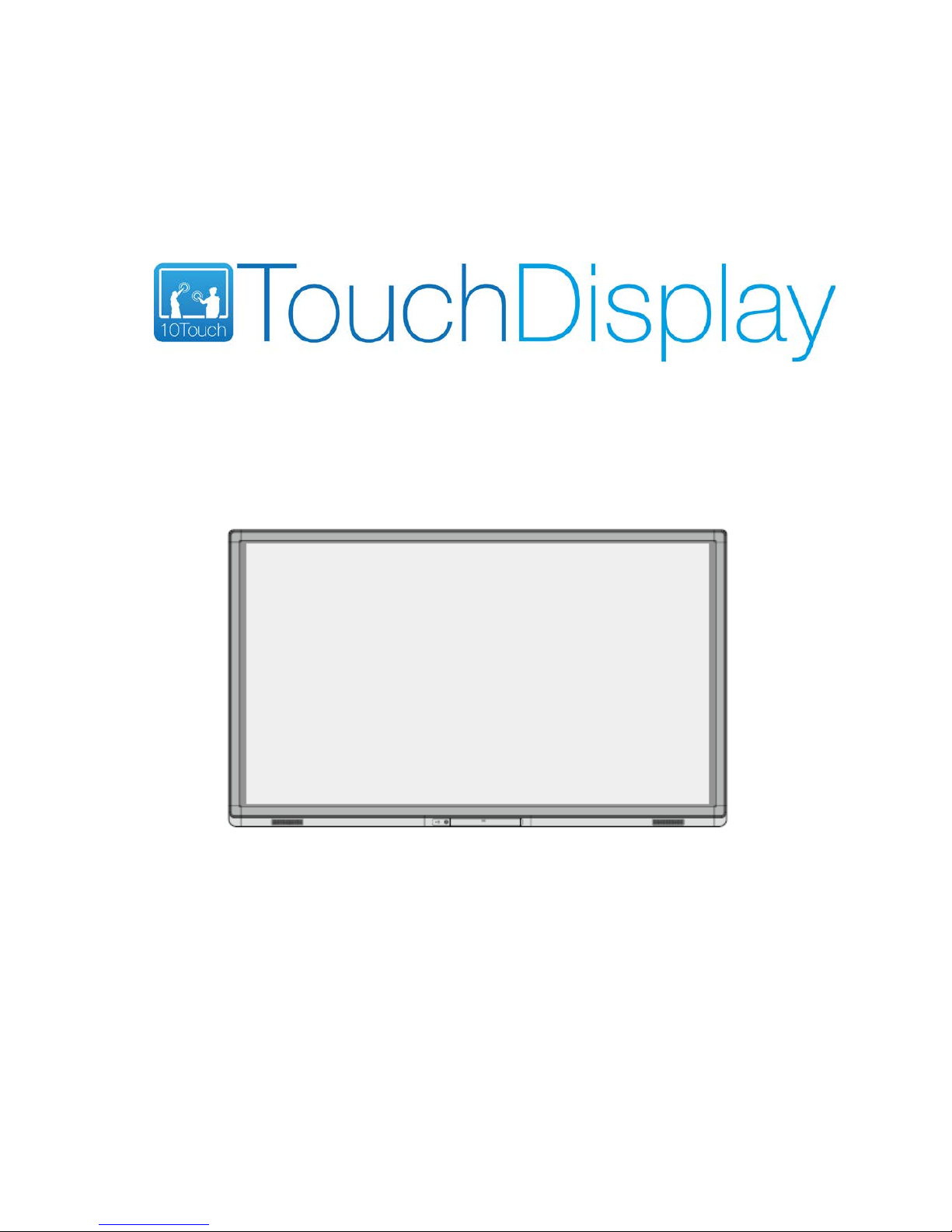
80” INTERACTIVE PANEL
USER GUIDE
Page 2
Welcome:
Thanks for purchasing this product. Please read the instructions carefully before using this
product.
This device complies with part 15 of the FCC Rules. Operation is subject to the following
two conditions: (1) This device may not cause harmful interference, and (2) this device
must accept any interference received, including interference that may cause undesired
operation.
NOTE 1: This equipment has been tested and found to comply with the limits for a Class
B digital device, pursuant to part 15 of the FCC Rules. These limits are designed to
provide reasonable protection against harmful interference in a residential installation.
This equipment generates, uses and can radiate radio frequency energy and, if not installed
and used in accordance with the instructions, may cause harmful interference to radio
communications. However, there is no guarantee that interference will not occur in a
particular installation. If this equipment does cause harmful interference to radio or
television reception, which can be determined by turning the equipment off and on, the
user is encouraged to try to correct the interference by one or more of the following
measures:
Reorient or relocate the receiving antenna.
Increase the separation between the equipment and receiver.
Connect the equipment into an outlet on a circuit different from that to which the
receiver is connected.
Consult the dealer or an experienced radio/ TV technician for help.
NOTE 2: Any changes or modifications to this unit not expressly approved by the party
responsible for compliance could void the user’s authority to operate the equipment.
The symbol of the crossed out wheeled bin indicates this product should not be placed in
municipal waste. Instead, you need to dispose of the waste equipment by handing it over
to a designated collection point for the recycling of waste electrical and electronic
equipment.
Page 3

3
Contents
Contents........................................................................................................................................ 3
1 Installation Requirements ..................................................................................................... 8
1.1 Mounting ................................................................................................................................................................ 8
1.2 V entilation ............................................................................................................................................................... 8
2 Introduction ............................................................................................................................ 10
2.1 Characteristics ...................................................................................................................................................... 10
2.2 Outer Appearance ................................................................................................................................................. 11
2.3 Remote Controller ................................................................................................................................................ 15
3 Basic Operation ...................................................................................................................... 17
3.1 Power On .............................................................................................................................................................. 17
3.2 Power Off ............................................................................................................................................................. 18
3.3 Software Installation ............................................................................................................................................. 19
3.4 Software Uninstall ................................................................................................................................................ 19
3.5 Software Calibration ............................................................................................................................................. 19
3.6 Positioning Method for Windows 7 ...................................................................................................................... 21
4 Assemble OPS Computer .................................................................................................... 24
5 Select Signal Channel ........................................................................................................... 25
6 Menu ........................................................................................................................................ 26
6.1 Picture ................................................................................................................................................................... 26
6.2 Sound Mode.......................................................................................................................................................... 26
6.3 Setting ................................................................................................................................................................... 27
6.4 Time ...................................................................................................................................................................... 27
6.5 Parental Control .................................................................................................................................................... 28
7 Multi-Media ............................................................................................................................. 29
8 ECO Mode ............................................................................................................................... 33
9 Serial Port Control ................................................................................................................. 34
10 Specifications of PC Mode (VGA Input) ........................................................................ 36
11 Formats Supported by USB Mode ................................................................................... 37
12 FAQ & Troubleshooting .................................................................................................... 38
Page 4

4
13 Maintenance Tips ................................................................................................................ 41
14 Specifications ....................................................................................................................... 42
Page 5
5
Safety Instruction
For your safety, please read the following instruction before you use the product. Serious injury or property loss
may be caused by improper operations. Do not try to repair the product by your own.
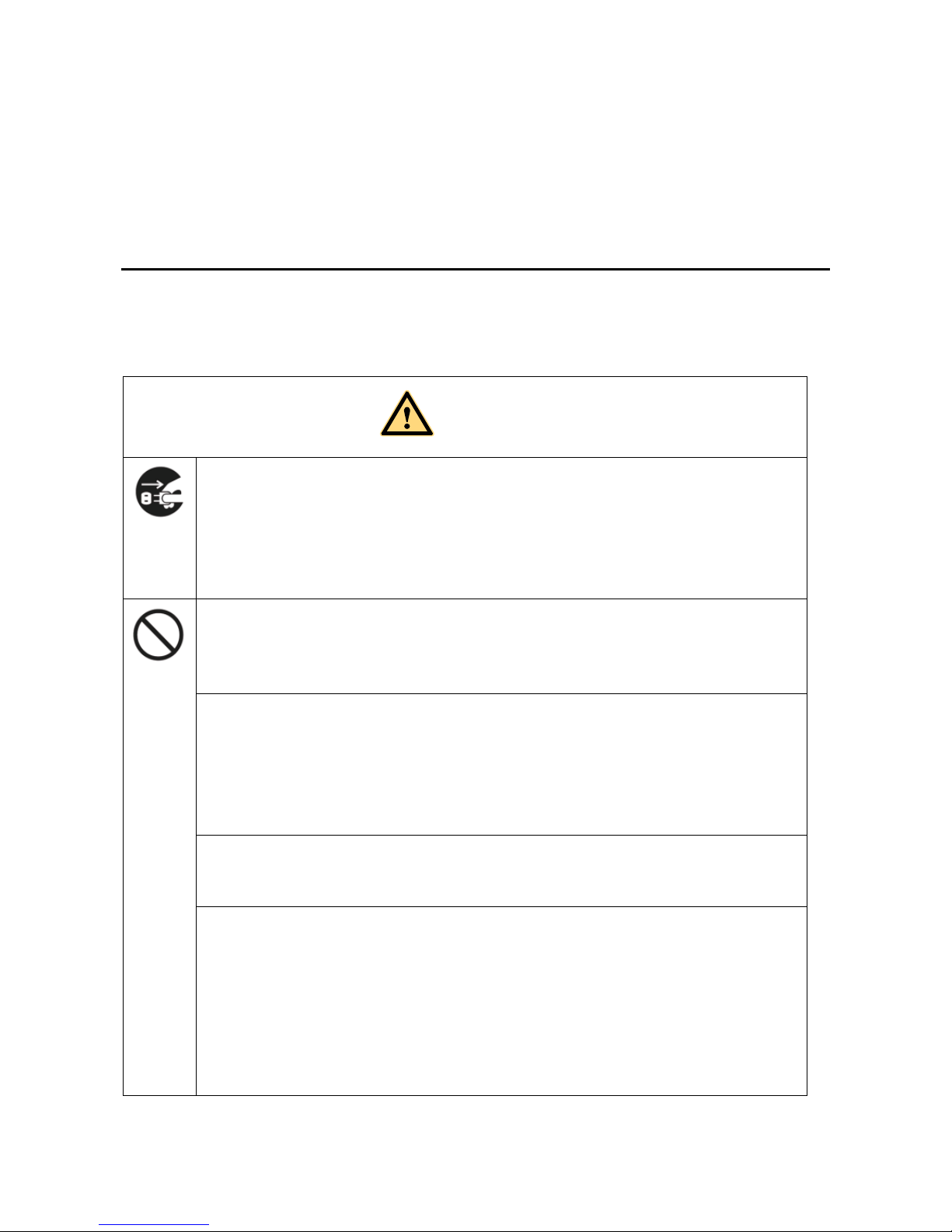
WARNING
Disconnect the product from power supply immediately if major failures occur.
The major failures include the following:
Smoke, peculiar smell or abnormal sound is discharged from the product.
No image or sound is displayed, or the image error occurs.
In the preceding scenarios, do not continue to use the product, disconnect power supply
immediately and contact professional staff for troubleshooting.
Do not drop liquid, metal or combustible into the product.
If any liquid or metal is dropped into the product, power off the product and disconnect power
supply, then contact professional staff for solutions.
Pay attention to the children when they are close to the product.
Do not damage the power cable.
Do not damage, change, wind, bend, heat or drag the power cable forcibly.
Do not put weights (such as the product itself) on the power cable.
Do not drag the cable forcibly when you pull out the power plug. If the power cable is
damaged, please contact the local distributor to repair or replace it.
The power cable in the accessory box is for this product only. Don't use it on other devices.
Put the product on a stable surface.
An unstable surface includes and does not limit to an inclined plane, a shaky stand, desk or
platform, which might cause the turnover and damage.
Use the battery correctly.
Galvanic corrosion, electric leakage and even fire may be caused by improper battery usage.
It is recommended to use the designated type of battery and install the battery by correct
electrodes (positive and negative electrodes).
Do not install and use new battery with the used one.
Take out the battery if the remote control is not used in a long period.
Do not expose the battery under overheated environments such as sunlight and firing.
Dump the used battery based on local regulations.
Page 6
6
WARNING
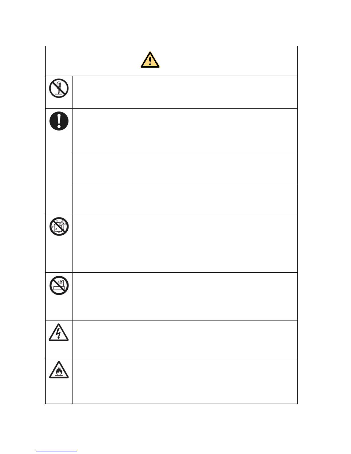
Do not open the cover or change the product by your own.
High voltage components are installed in the product. When you open the cover, high voltage,
electric shock or other dangerous situations may occur. If inspection, adjustment or maintenance
is required, contact the local distributor for help.
Use the specified power supply.
Do not use any types of power cables other than the one provided with the product to prevent
the product from being damaged.
Use a three-wire socket and ensure that it is properly grounded.
Pull out the power plug from the socket if the product is not used in a long period.
Before you move the product, disconnect all the external connections and separate all the
toppling preventing devices.
Move the product carefully to prevent it from being hit or squeezed, especially the screen, which
may cause injury if broken.
Clean the dust and metal on the power plug regularly.
When you are cleaning, fire or electric shock may be caused if the product is powered on.
Keep in mind to pull out the power plug before cleaning it by using a dried cloth.
Do not put items on the top of the product.
Do not put items, such as a container for liquid (a vase, flowerpot, cosmetics or liquid
medicine), on the top of the product.
If any water or liquid is spilled on the product, short circuit may occur and cause fire or
electric shock.
Do not tread on the product or hang any items on the product.
The power cable in the accessory box is for this product only. Don't use it on other devices.
Do not install the product in an improper place.
Do not install the product in humid places, such as the bathroom, the shower room, the place
near windows or outdoor environments where experience rain, snow or other harsh weather.
The product installation is also required to avoid a place around by hot spring vapor. The
preceding environments may cause faults or electric shock under extreme conditions.
Do not put exposed fire source, such as an ignited candle, on the product.
Pull out the power plug during thunderstorms.
Do not touch the product when lighting to avoid electric shock.
Install or place components which power supply voltage is high enough to cause personal
injury in places out of the reach of children.
Do not cover or block up any vents on the product.
The overheated components may cause fire, damage the product and shorten the service life.
Do not put the venting surface of the product facedown.
Do not install the product on a carpet or bed clothes.
Do not use a cloth such as the table cloth to cover the product.
Page 7
7
WARNING
Do not touch the power cable with wet hands to avoid electric shock.
Please pay attention to the preceding warning information. Otherwise, serious injury, incidents, even
death may be caused.
CAU
TION
Do not install the product in high temperature environments.
Do not install the product near heat source, such as the radiator, the heat reservoir, the
stove or other heating devices.
Do not expose the product under sunlight, which may cause high temperature and
subsequent faults in the product.
For transport:
Pack the product for mobility or maintenance by using the cartons and cushioning
material provided with the product.
Vertically move the product during transport. The screen or other components are
easily broken if the product is moved by an improper way.
Keep away from the product when you use a radio.
The product design to prevent radio interference complies with the international EMI
standard. However, the interference still exists and causes noise in the radio.
If noise occurs in the radio, try the following solutions.
Adjust the direction of the radio antenna to avoid the interference from the product.
Keep the radio away from the product.
Advice for watching:
Use the product in an environment with comfortable light. It is harmful to your eyes to
watch in a too bright or too dark environment.
Relax your eyes after a period of time for watching.
When you are watching, the distance which is 3 to 7 times of the screen height should
be kept, and it is the best distance to protect eyes and prevent eyestrain.
Adjust the volume to an appropriate level, especially at night.
Please pay attention to the preceding caution information. Otherwise, minor injury or product
damage may be caused.
Page 8
8
1 Installation Requirements
1.1 Mounting
You can choose the potable or wall mounting method according to your needs. Wall
mounting can substantially save the space.
If you choose portable mounting, use the mounting rack or support. If you want to use a
self-made mounting rack, the bearing capacity of the rack should be at last four times of the
actual weight of the display. The bearing capacity of the mounting support must be at least
four times of the actual weight of the display to ensure steadiness of the interactive panel.
When you choose wall mounting, the bearing capacity of the mounting surface must be at
least four times of the weight of the display. When the mounting surface is a wall or ceiling of
a building, the wall must be built with solid bricks, concrete or materials of equal intensity. If
you need to mount the display on a loose surface such as an old brick wall, wood plank wall,
solid brick wall, metal or non-metal structure wall, or a wall with a thick decoration layer,
take necessary consolidating measures to ensure that the display is steadily mounted.
1.2 Ventilation
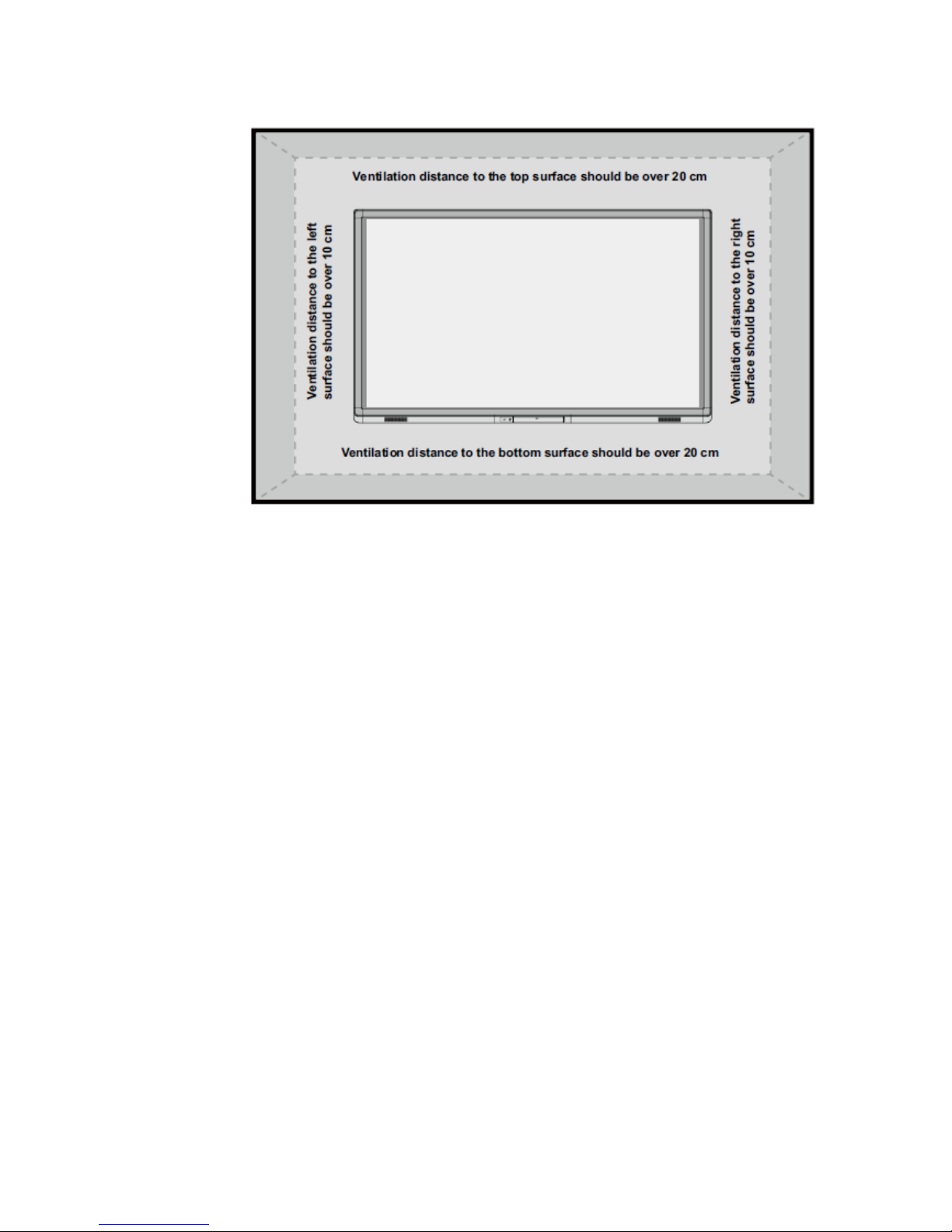
Ventilation
requirements
Distance to the mounting surface (cm)
Nominal power
Left and right
sides
Top Bottom Back
Larger than 100W 10 20 20 10
WARNING
If the product is installed inside a wall or a cabinet, in addition to the preceding requirements,
the ventilation area around the bottom, top and two sides must be at least 50% of the sealing
surface to ensure proper ventilation.
Page 9
9
Page 10

10
2 Introduction
Thank you for buying Interactive touch screen. As our latest independently developed and
produced human-machine interactive products, the Interactive touch screen are
multi-functional teaching displays for interactive teaching, digital demonstration, multi-media
presentation, touch operations and handwriting. They are well designed and produced to meet
needs of education applications, and provide a user-friendly experience, digital intelligent
control as ideal apparatus for modern education. You can use your fingers or opaque objects to
write, edit and delete any things on them.
2.1 Characteristics
Specially designed for teaching and meeting systems.
Integrating user management module to realize user adding/deleting, switching and user
information customized functions that coincide with users’ preference.
Adopting infrared array scanning and sensing technology, HID drive-free, plug-and-play
Outstanding display edit functions, supporting instant editing.
Multiple optional pens, width and colors; simulative brushes that are vigorous.
Multiple backgrounds, supporting customized background with any images and graphs
inserted.
Support dual-point touch and multi-finger roaming; simulative mouse operation.
Supporting identification of handwritten Chinese, English, number and special
characters.
Supporting conversion of handwritten files into other formats including PDF, JPEG, GIF,
PNG, TIFF and BMP.
Intelligent geometric figure identification, able to identify multiple figures with high
recognition rate and multi-pen identification.
Vector-based graphic processing with high compression rate and low distortion.
ECO back-light mode, lower power consumption.
High luminance and contrast display to ensure clear display under straight light or in
outdoor environment.
Supporting SD card.
Page 11
11
2.2 Outer Appearance
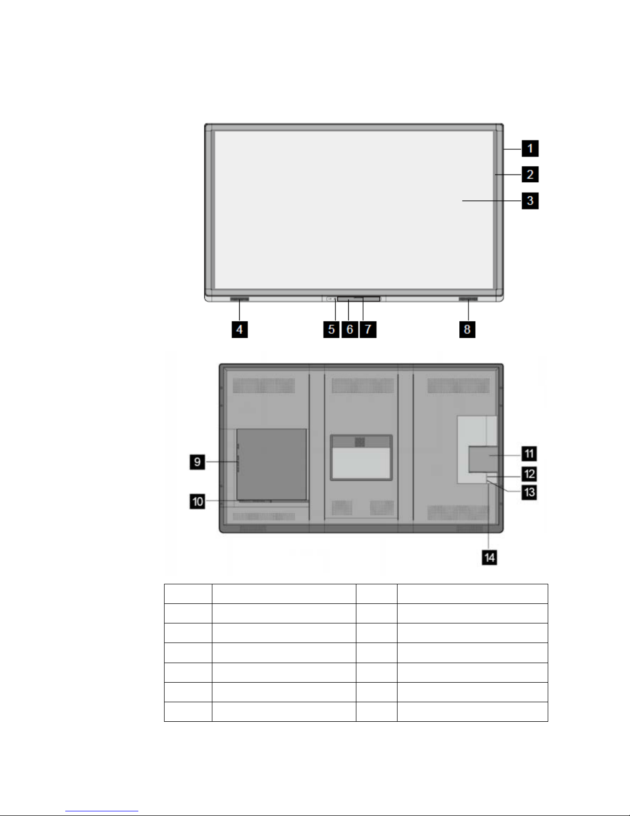
1 Enclosure 8 Right Loudspeaker
2 Infrared Frame 9 Rear Port Panel 1
3 Screen 10 Rear Port Panel 2
4 Left Loudspeaker 11 OPS Por t
5 Power 12 Power Outlet
6 Control Panel 13 Rocker Switch
7 Front Cover Plate 14 Reset
Page 12
12
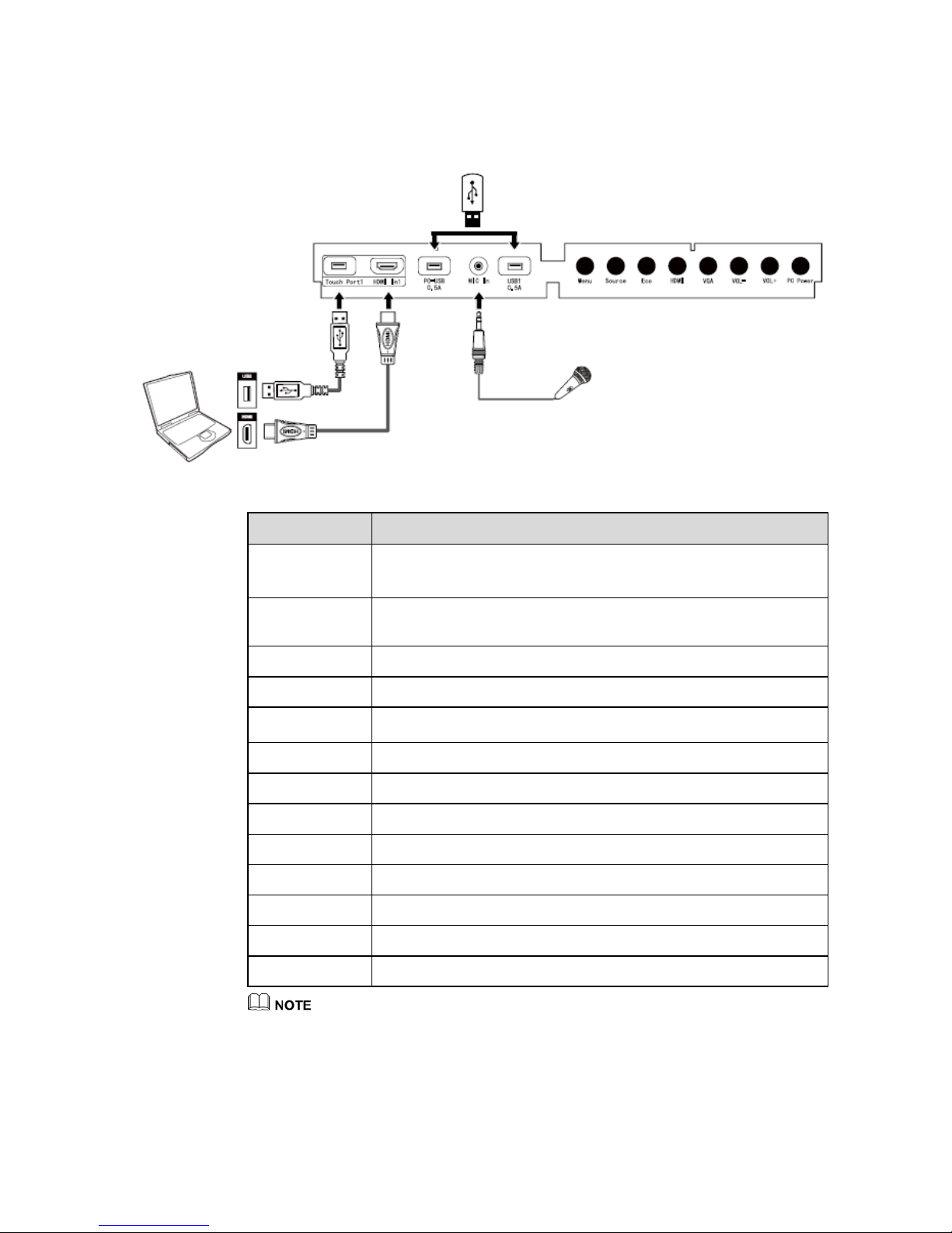
Control Panel
Name Function Description
Touch Port1 The touch control terminal 1 which is used to connect to a PC.
Touch port1 only supports 2m USB cable.
HDMI In1
The input terminal 1 for high definition signal, which is used with the
touch port 1 to operate PC in the way of touch control.
PC-USB 0.5A The USB port for the OPS.
MIC In The external microphone port.
USB1 0.5A
USB port for Digital Media Player
(DMP) signal channel.
Menu Enter the function menu.
Source Enter the menu to select a signal source.
Eco Switch among three modes: energy-saving, automatic, and standard.
HDMI Switch over to HDMI signal source.
VGA Switch over to VGA signal source.
VOL- Decrease volume.
VOL+ Increase volume.
PC Power Power on or power off the OPS.
Touch Port1 corresponds to HDMI In1 and VGA In1.
Touch Port2 corresponds to HDMI In2.and VGA In2.
Page 13
13
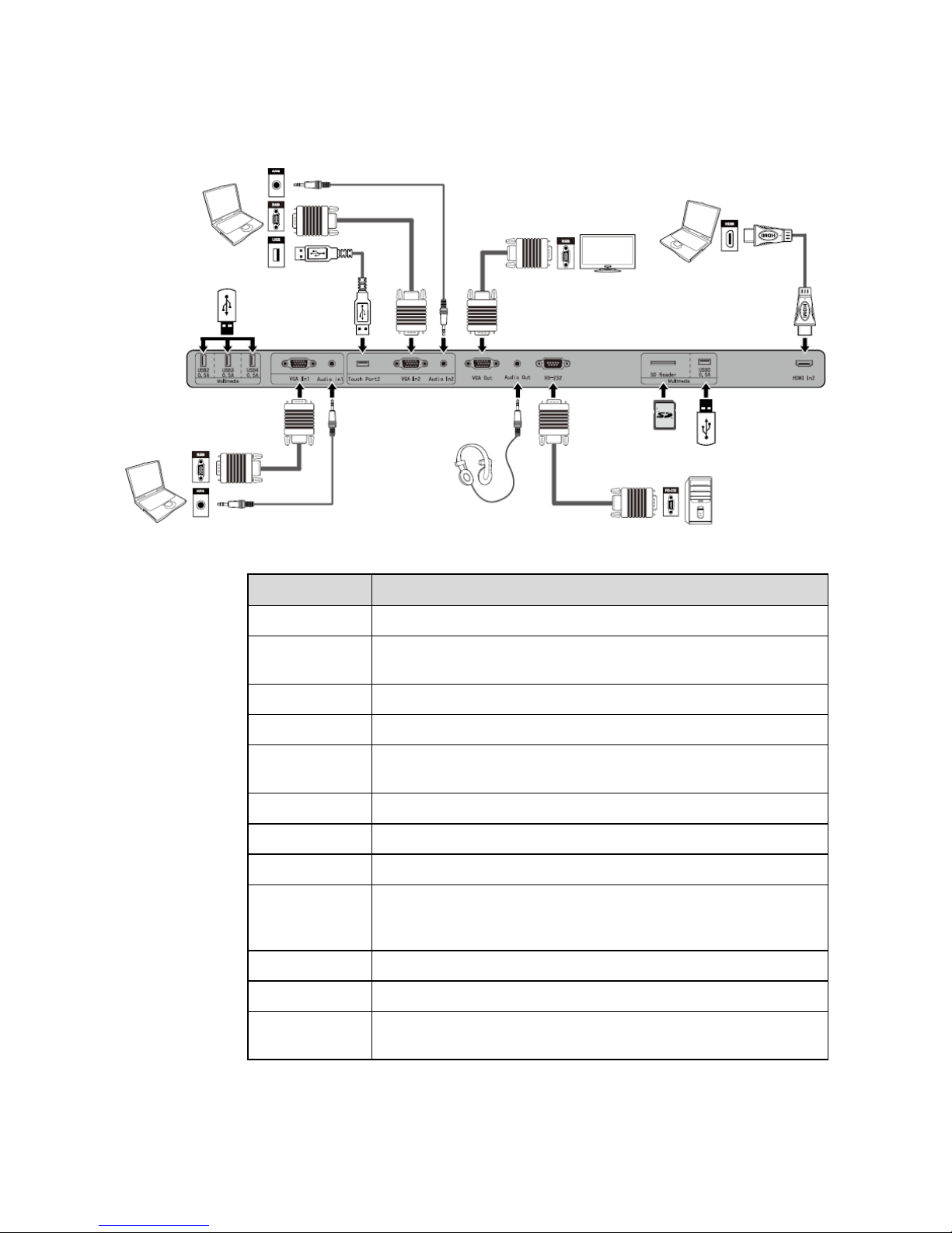
Rear Port Panel 1
Name Function Description
USB2-USB4 USB port for DMP signal channel.
VGA In1
The VGA port for an external PC, which is used with the “Touch
port1” to operate the PC in the way of touch control.
Audio In1 The “Audio In1” is used with the VGA port for an external PC.
Touch Port2 The terminal 2 for touch control signal.
VGA In2
The VGA port for an external PC, which is used with the “Touch
port2” to operate the PC in the way of touch control.
Audio In2 The “Audio In2” is used with the VGA port for an external PC.
VGA Out VGA output port.
Audio out The terminal for external loudspeaker boxes or headphones.
RS-232
The input port for series signals, which is used by specific control
device of serial port to input serial port protocol in order to control the
panel.
SD Reader SD card reader.
USB5 USB port for DMP signal channel.
HDMI In2
The input terminal 2 for high definition signal, which is used with the
touch port 2 to operate PC in the way of touch control.
Page 14
14
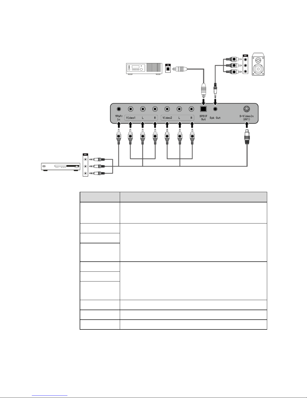
Rear Port Panel 2
Name Function Description
YPbPr In
The component video terminal, which is used to connect to video
devices such as the HD digital signal STB, the satellite receiver, DVD
players and other HD displayers or TV equipment.
Video1
An array of audio and video input terminals, which are used to input
audio and video signal.
Video: Video input terminal.
L: Left audio input terminal.
R: Right audio input terminal.
L
R
Video2
An array of audio and video input terminals, which are used to input
audio and video signal.
Video: Video input terminal.
L: Left audio input terminal.
R: Right audio input terminal.
L
R
SPDIF Out SPDIF Output.
Spk Out Audio output terminal.
S-VideoIn (AV1) S-Video Input.
Page 15
15
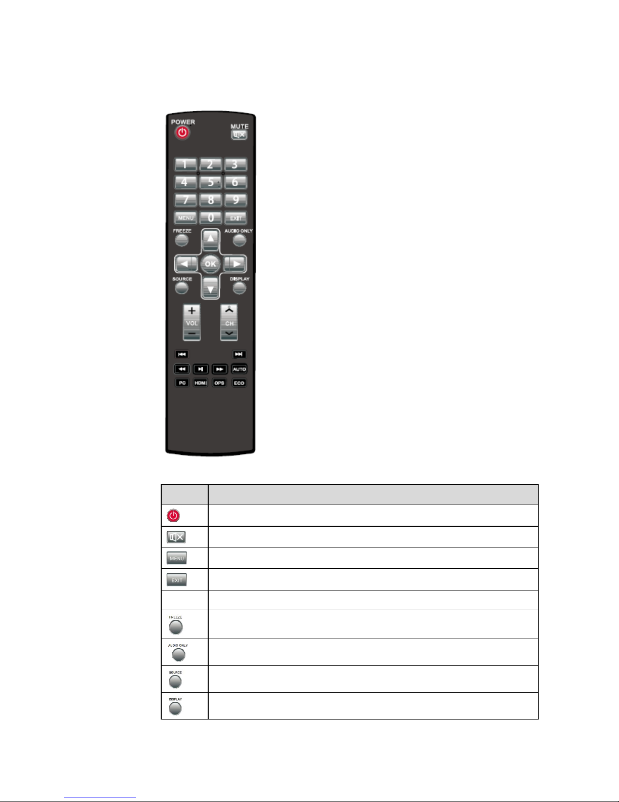
2.3 Remote Controller
Items Functions Description
Power on or standby
Mute
Menu or return to parent menu
Quit
0-9
Select TV channel or enter number
Freeze
Enable listen alone mode
Display or quit signal source menu
Show current signal status or information
Page 16
16
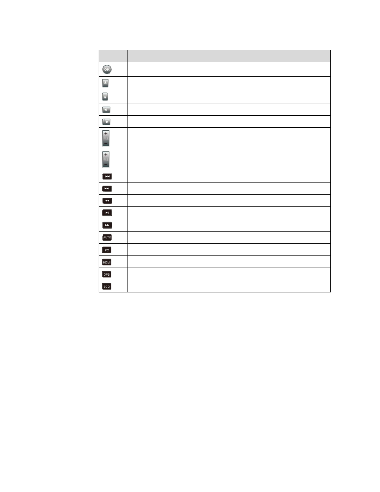
Items Functions Description
Confirm selected item
Up direction button
Down direction button
Left direction button
Right direction button
Adjust volume
Select channel
Previous media file
Next media file
Rewind
Play/Pause
Fast forward
Auto adjust window under PC signal source
Switch to PC input signal
Switch to HDMI input signal
Switch to OPS input signal
Switch to ECO mode
Page 17
17
3 Basic Operation
3.1 Power On
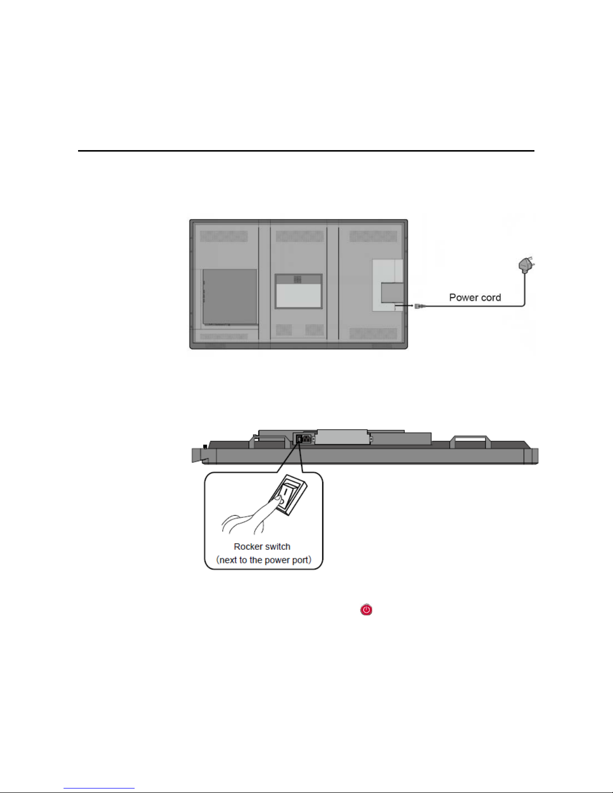
Step 1 Power the interactive panel with a 100-240V 50/60Hz AC power supply.
Step 2 Connect the panel to the power supply. Switch on the rocker switch (on the right of the
rear of the panel, next to the power port) to enter the standby status. The power LED
turns red.
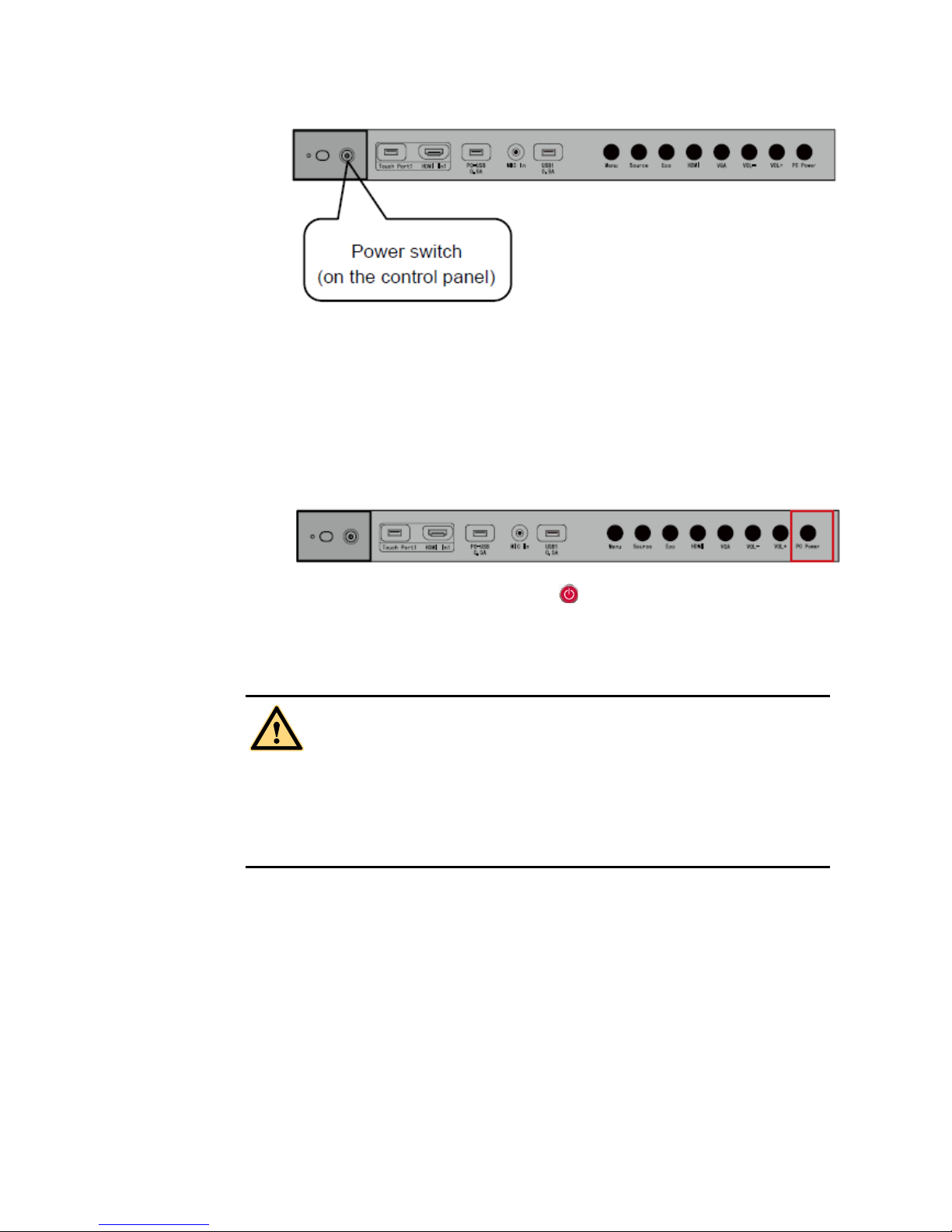
Step 3 Press power switch on the control panel or
on the remote controller to turn on the
interactive panel. The OPS computer is started. The power LED turns green.
Page 18
18
3.2 Power Off
Step 1 Press PC Power to turn off the OPS computer (for all-in-one models only).
Step 2 Press power switch on the control panel or
on the remote controller to enter the
standby status. The power LED turns red.
Step 3 Under the standby status, switch off the rocker switch to turn off the interactive panel.
WARNING
Please turn off the OPS computer before the interactive panel. Otherwise, the computer
can be damaged.
Please disconnect the interactive panel from power after the panel enters standby status.
Otherwise, the panel can be damaged. A sudden power failure can damage the interactive
panel.
Page 19
19
3.3 Software Installation
Recommended configuration:
− CPU: Inter (R) Core i3 2.27GHz or AMD CPU with equivalent performance
− Memory: 1GB
− Hard drive: 1GB
− Graphics card: supports DirectX 9 or above
If the interactive panel is equipped with the latest version of handwriting software in the
PC before being delivered, please skip the step.
HID drive-free function only applies for Vista, Windows 7or higher version (realize the
functions of multi-touch etc.). The touch LED display with Windows XP version should
install/run the software for normal use.
Step 1 Insert the official USB cable into the USB ports of the computer and touch LED
display.
Step 2 Insert the official software installation disk into the computer.
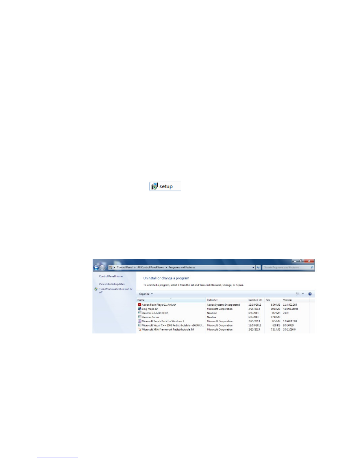
Step 3 Double click the
, follow the instructions and complete the installation
of the touch LED display software.
Step 4 The computer needs to restart so as to activate the software af ter ins tallatio n c o mpleted .
Save all the files in the computer and restart.
3.4 Software Uninstall
If you are sure to delete the touch LED display software from your computer, click Add or
Remove Programs in Control Panel. Choose Ideamax and click Uninstall to uninstall.
3.5 Software Calibration
To work normally, the handwriting of the projected image on the touch LED
display should coincide with the actual one so as to calibrate accurately. The
following situations need calibration.
When you first use the interactive LED panel.
Re-install the drive program.
Page 20
20
When you connect the panel to another PC.
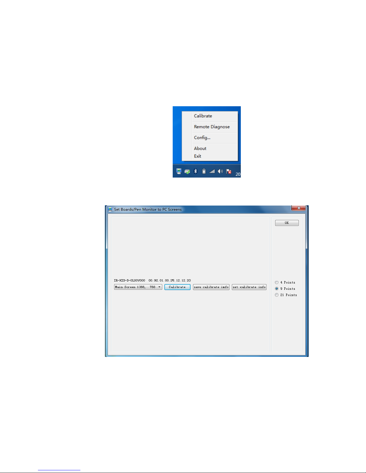
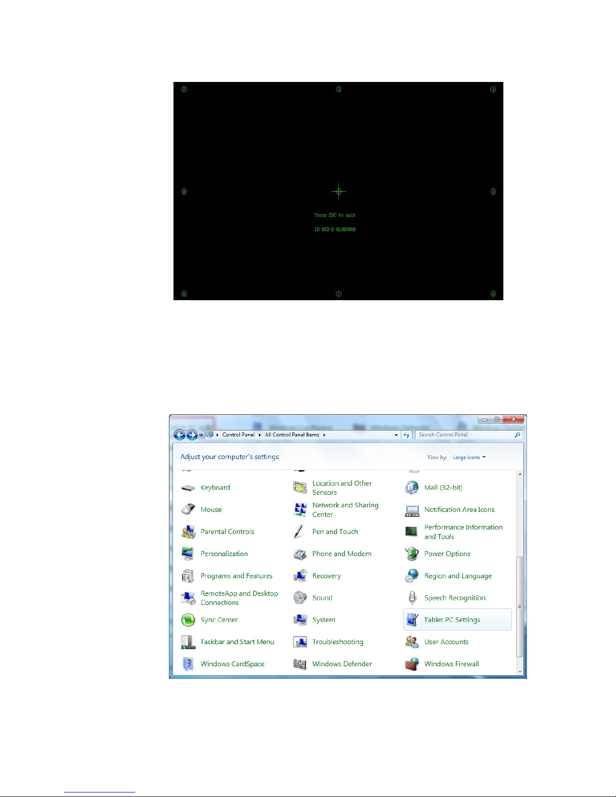
The handwriting panel adopts nine-point calibration method. The position process is
described as follows:
Step 1 Connect the panel and run the drive program.
Step 2 Click the handwriting drive icon on the right bottom of the panel to show the following
image.
Step 3 Select 9 Points and click Calibrate.
Step 4 Use the pen to click and hold the center of the flickering cross. Do not release it until
the flickering cross moves to the next positioning point. Complete the calibration
process as instructed. After it completes, you will return to the desktop automatically.
Page 21
21
3.6 Positioning Method for Windows 7
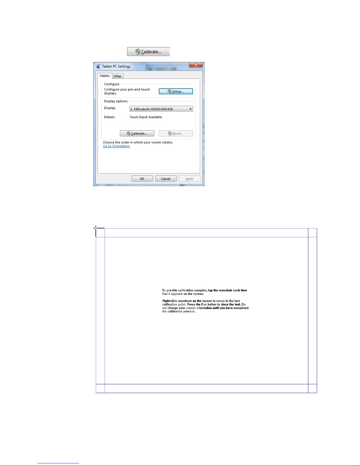
Step 1 Connect the interactive panel to PC using the USB lead via the USB interface on the
panel.
Step 2 Select Tablet PC Setting on Control Panel.
Page 22
22
Step 3 Select on the setting window.
Step 4 Use the pen to click and hold the center of the flickering cross. Do not release it until
the flickering cross moves to the next positioning point. Complete the positioning
process as instructed.
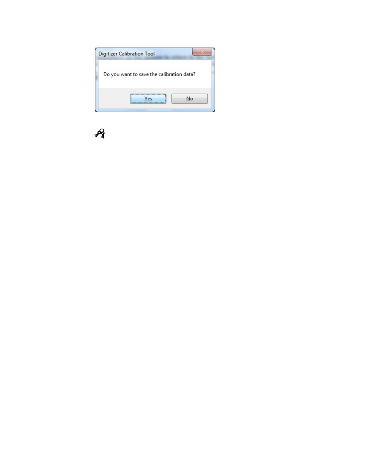
Step 5 Click Yes after its completed.
Page 23
23
Tips
To ensure the handwriting accuracy, use the pen provided together with the interactive panel rather a
finger to perform calibration.
Calibration erro rs may cause touch functions of the interactive panel fail. In that case, please
perform positioning again.
Tap ESC on the keyboard during the positioning process to cease positioning.
The calibration interface varies between different software versions. P lease follow instructions
provided on the actual interface.
Page 24
24
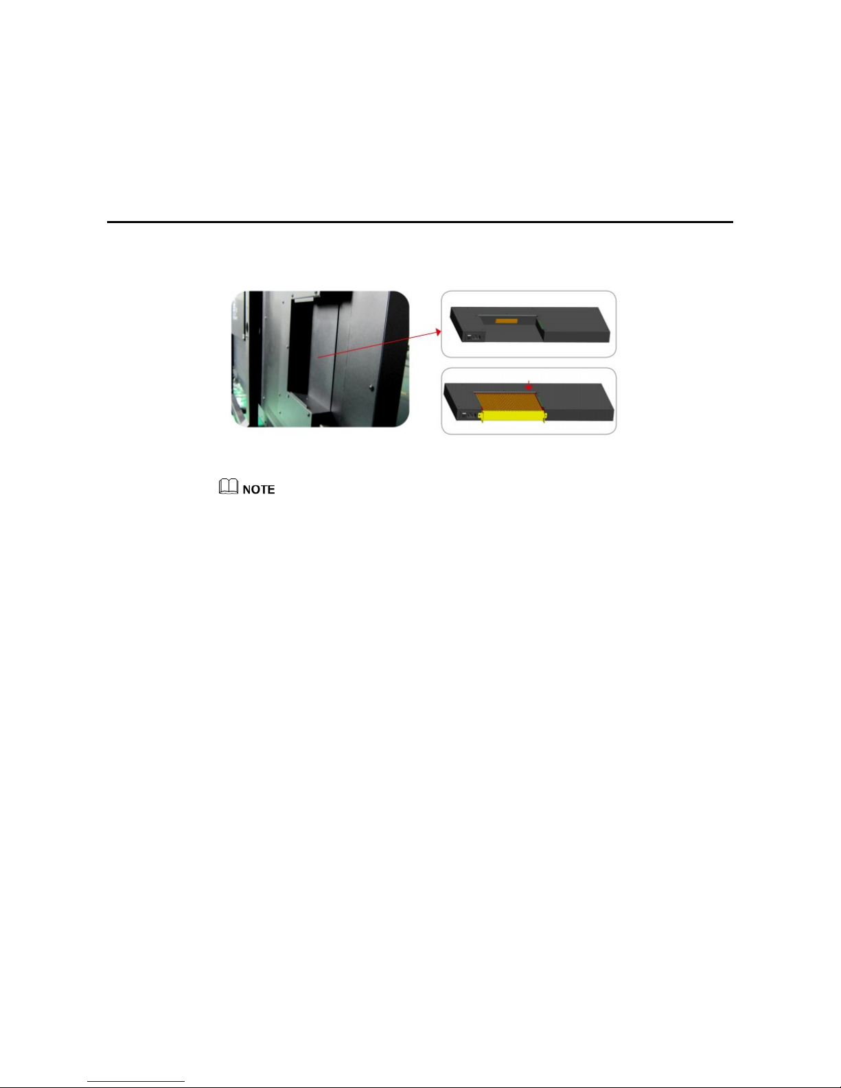
4 Assemble OPS Computer
Insert OPS computer into the slot and fasten it with two M4 screws on the top and bottom.
The OPS computer is not plug-and-play. Disconnect the inter active panel from the power before
inserting the OPS computer.
Page 25
25
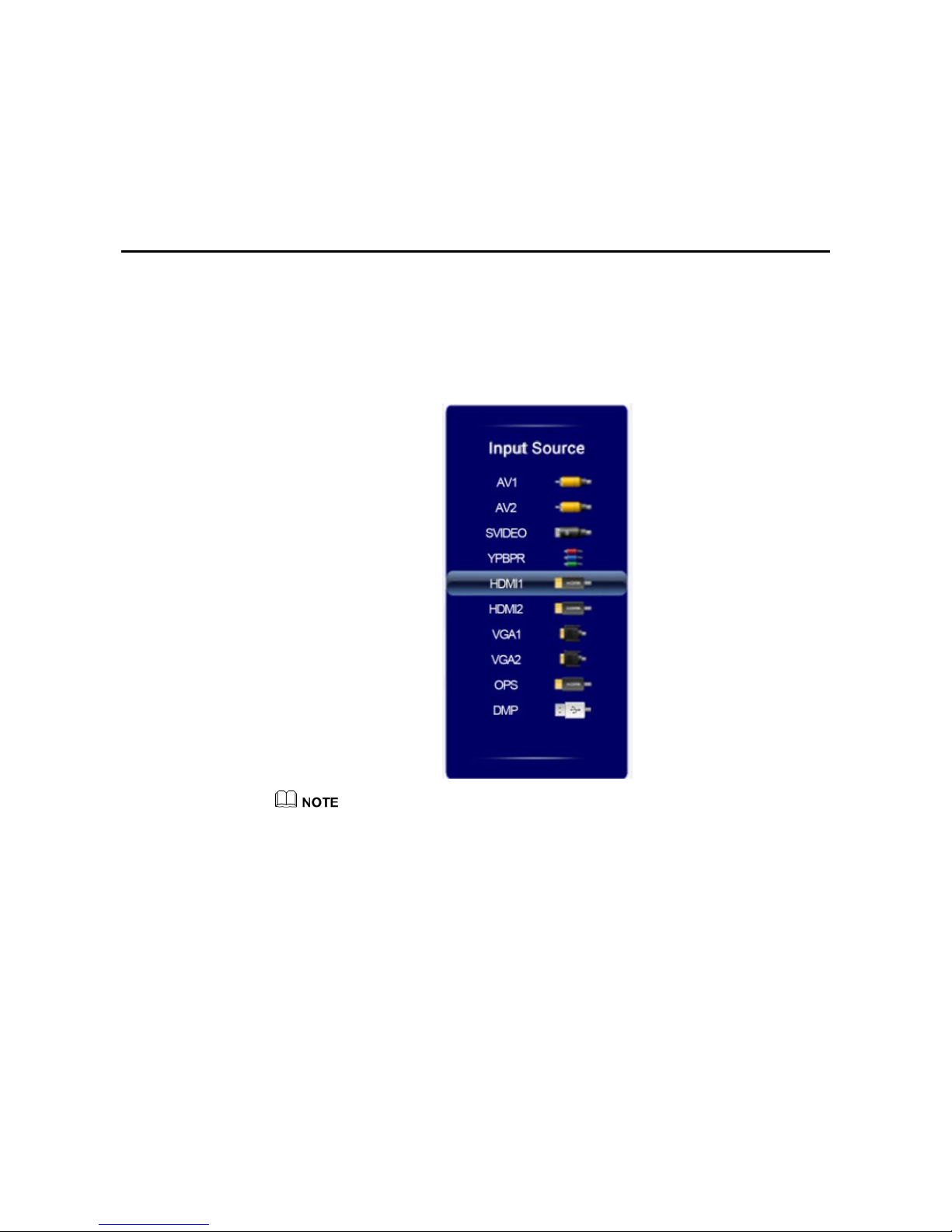
5 Select Signal Channel
There are three ways to select a signal channel:
Press SOURCE on the remote controller.
Press Source on the control panel of the interactive panel.
The system shows the following interface. Press ▲/▼ to select an option and press OK. Y ou
can also click an icon on the interface.
The interactive panel will automatically detect signals when it is started or there is no signal.
Page 26
26
6 Menu
After switching to selected signal source, press MENU on the remote controller. A menu is
displayed, including Picture, Sound Mode, Setting, Time and Parental Control and
Settings. Scroll left and right on the screen or press ◄ or ► to switch between entries.
6.1 Picture
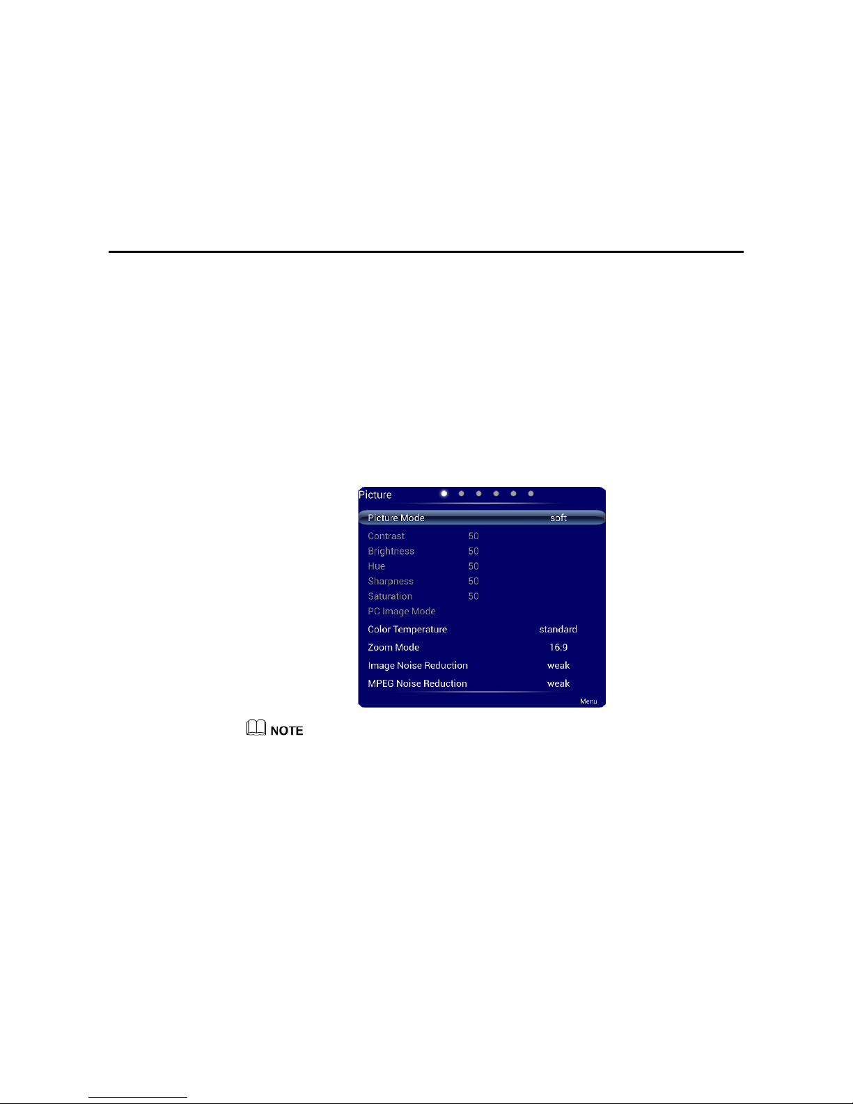
The Picture menu shows options including Picture Mode, Color Temperature, Zoom
Mode, Image Noise Reduction, and MPEG Noise Reduction. There are two ways to set it:
Click an icon and set it.
Press ▲/▼ to move the cursor onto an option. Press OK and press ◄/► to adjust the
value. Press EXIT to quit the menu.
When the image mode is User, you can adjust the contrast, brightness, hue, sharpness and saturation.
6.2 Sound Mode
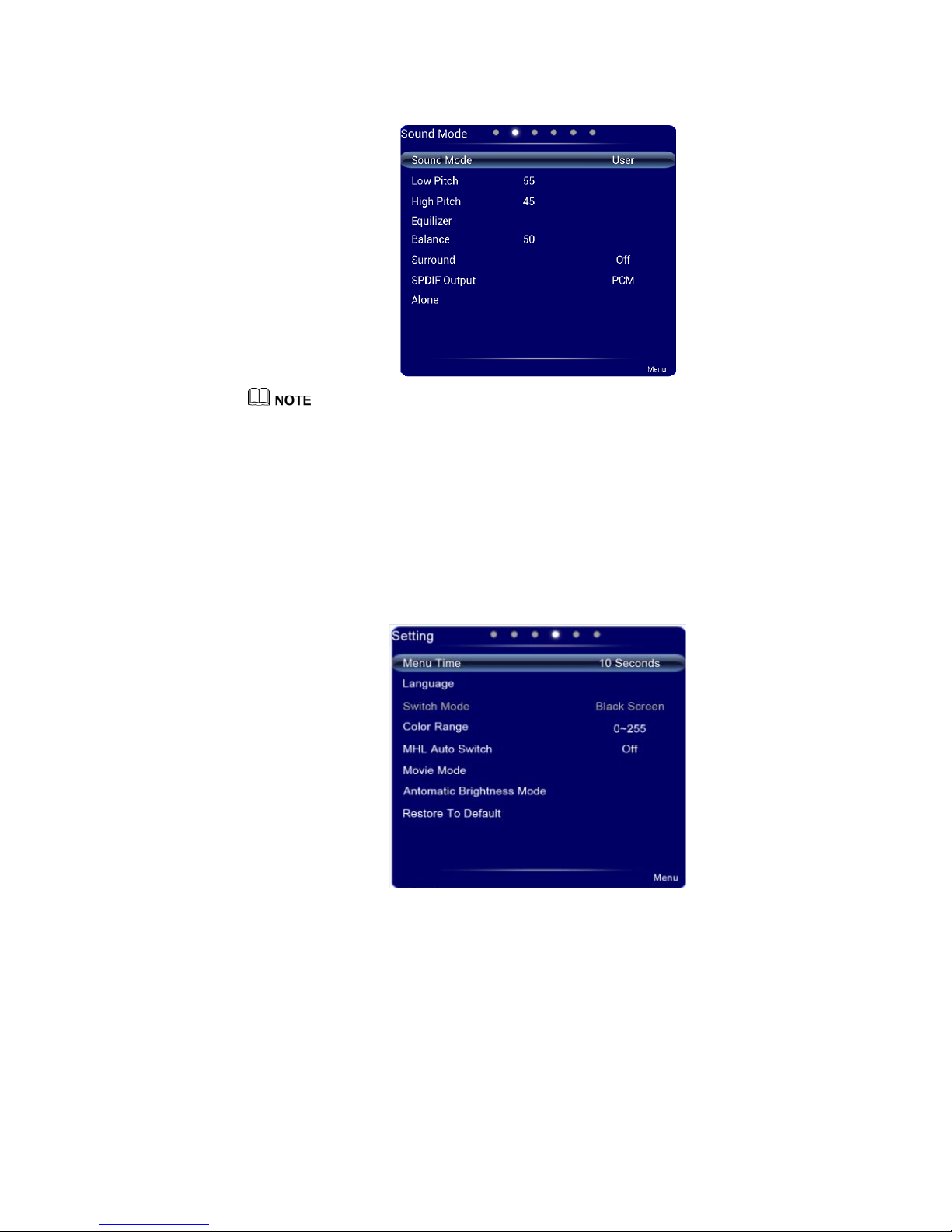
The Sound Mode menu shows options including Sound Mode, Low Pitch, High Pitch,
Equalizer, Balance, Surround, SPDIF Output and Alone. There are two ways to set it:
Click an icon and set it.
Press ▲/▼ to move the cursor onto an option. Press OK and press ◄/► to adjust the
value. Press EXIT to quit the menu.
Page 27
27
When the sound mode is set to User, you can adjust High Pitch and Low Pitch.
6.3 Setting
The Setting menu shows options including M e nu Time, Language, Switch Mode, Color
Range, MHL Auto Switch, Movie Mode, Antomatic Brightness Mode and Restore To
Default. There are two ways to set it:
Click an icon and set it.
Press ▲/▼ to move the cursor onto an option. Press OK and press ◄/► to adjust the
value. Press EXIT to quit the menu.
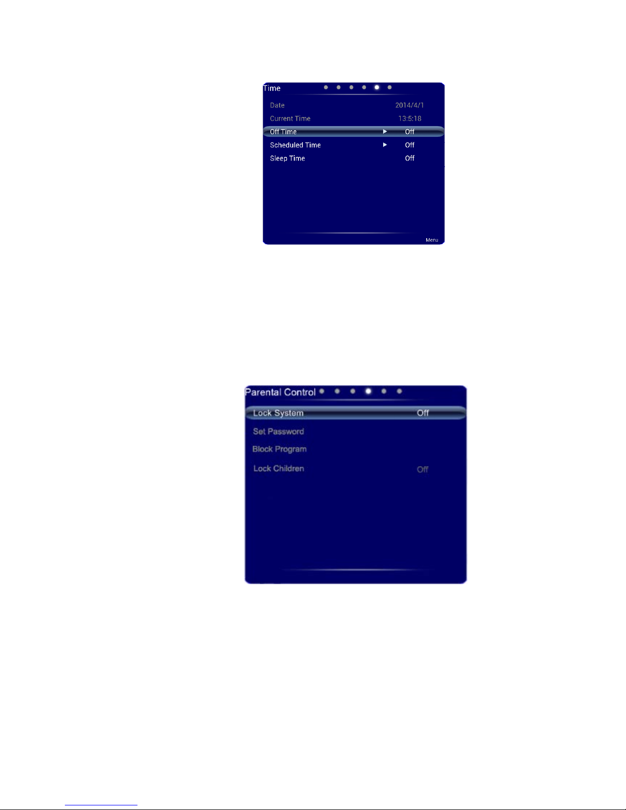
6.4 Time
The Time menu shows options including Date, Current Time, Off Time, Scheduled Time,
and Sleep Time. There are two ways to set it:
Click an icon and set it.
Press ▲/▼ to move the cursor onto an option. Press OK and press ◄/► to adjust the
value. Press EXIT to quit the menu.
Page 28
28
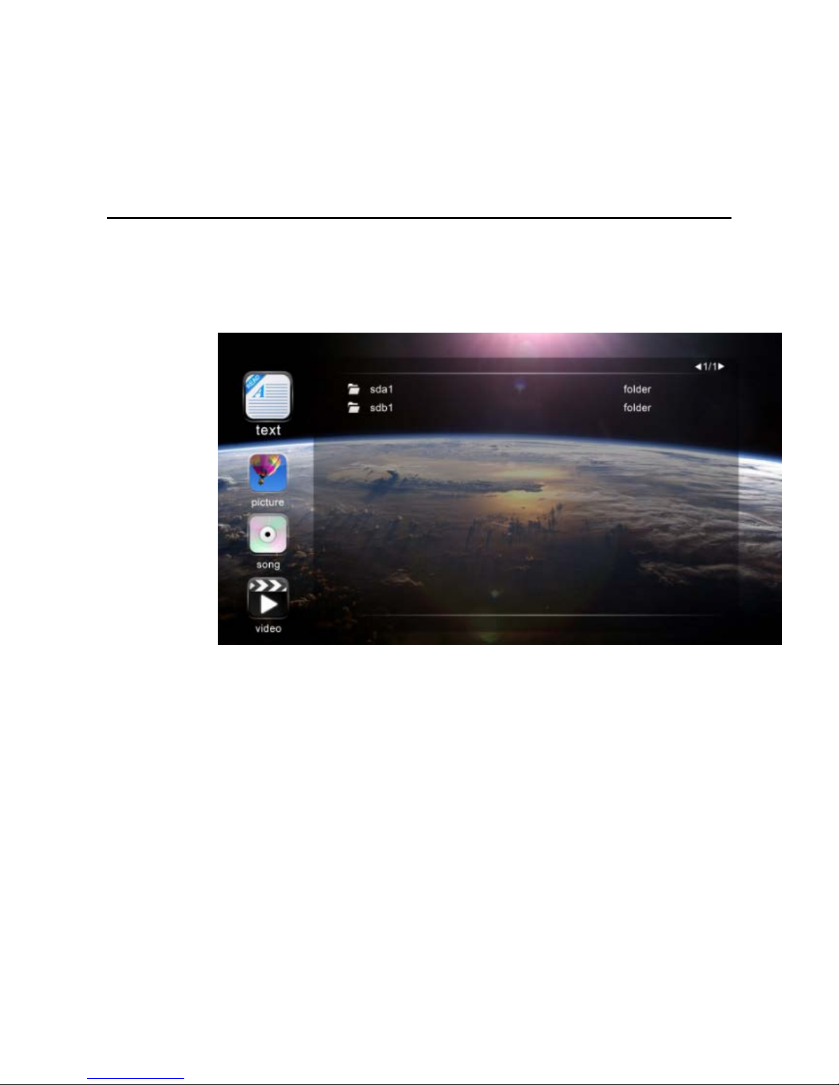
6.5 Parental Control
The Parental Control menu shows options including Lock System, Set Password,
Block Program, and Lock Children. The default password: 0000.
There are two ways to set it:
Click an icon and set it.
Press ▲/▼ to move the cursor onto an option. Press OK and press ◄/► to adjust the
value. Press EXIT to quit the menu.
Page 29
29
7 Multi-Media
Press SOURCE on the remote controller to display the list of signal sources. Press ▲/▼ to
switch to DMP signal channel. Press OK to enter the channel.
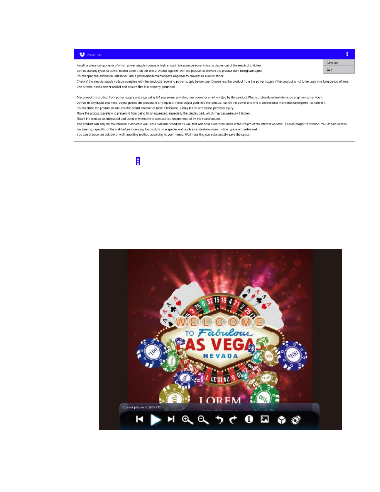
After you enter the multi-media signal source, the interface shows options including text,
picture, song and video. The color of the USB icon indicates if USB is detected. Blue means
USB is detected. Grey means no USB is detected.
Press ▲/▼ to select flash di sk or the type of content to be played.
Press ◄/► to switch flash disk and the type of content to be played.
Press OK to enter the catego r y.
When USB is detected, pres s OK to show content in the flash disk and select back to return to the prev i ous
menu.
Text
After entered text option, press ◄/► to select files to be displayed. Press OK to select a file.
Page 30
30
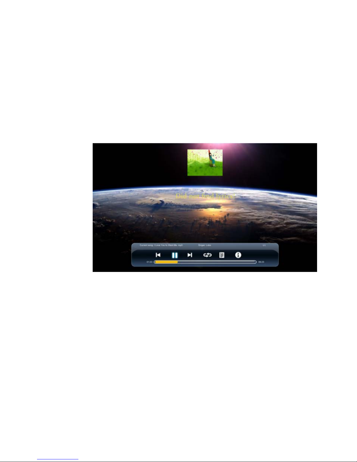
Click the icon
on the right hand up corner and follow the instruction below:
Editing file by clicking anywhere in the file.
Click Save file to save editing.
Click Quit to exit the file.
Picture
After entered picture option, press ◄/► to select images to be displayed. Press OK to select
or de-select an image. Press ►II to start or stop displaying.
Page 31
31
Press ► to show the operation function menu. Press ◄/► to select a function and press OK to use the
function.(The functions include: Play/Pause, Previous, Next, Zoom In, Zoon Out, Clockwise Rotation,
Counterclockwise Rotation, Information, Playlist , Set as wall paper and Playing setting.)
Press I◄ to display the previous image and ►I to display the next image.
Press EXIT to quit playing.
Song
After entered song option, press ◄/► to select music to be played. Press OK to select or
de-select a song. Press ►II to start or stop playing and shortcut buttons on the remote
controller to use relevant functions.
Press ►to show the operation function menu. Press ◄/► to select a function and press OK to use the
function. (The functions include: Previous, Play/Pause, Next, Play Mode, Playlist and Information.)
Press I◄ to play the previous song and ►I to play the next one.
The playing speed can be adjustable by dragging the bar.
Press EXIT to quit playing.
Video
After entered video option, press ◄/► to select movies to be displayed. Press OK to select or
de-select a movie. Press ►II to start or stop playing.
Page 32
32
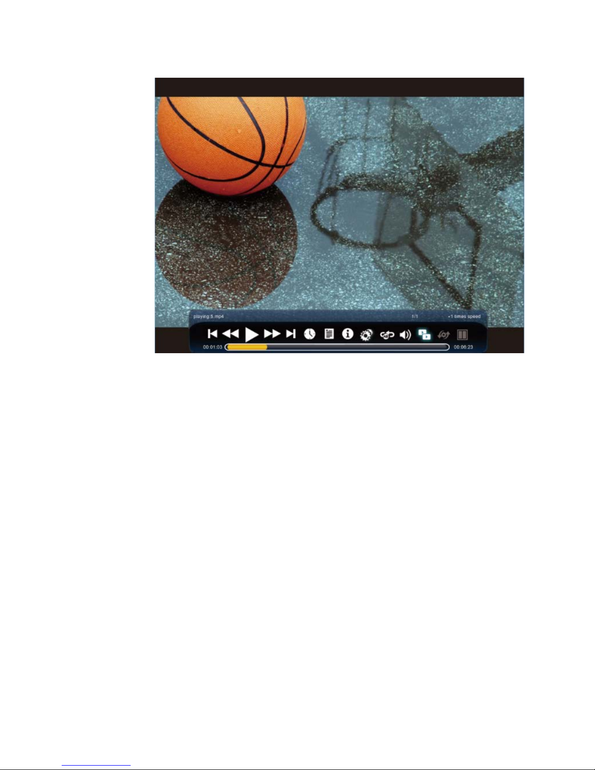
Press ►to show the operation function menu. Press ◄/► to select a function and press OK to use the
function.
Press ◄/► to select a function and press OK to use the function. (The functions include: Play/Pause, Fast
Reverse, Fast Forward, Previous, Next, Current playing statu
s, Playlist, Information, Playing setting, A-B
section repeat, Adjust volume, double screen, switch channel, and double screen s tatus.)
Press EXIT to quit playing.
Page 33

33
8 ECO Mode
Press ECO on the remote controller to enter the ECO mode (ECO-Auto-Standard). Press
this button to switch among the three modes.
The power consumption will be halved under the ECO mode.
Under the Auto mode, the display will automatically adjust the brightness of the screen
according to the light from the environment. When the surrounding light is strong, the
screen will bright up. When the surround light is weak, the screen will darken.
Under the Standard mode, the screen brightness will stay the same.
To save energy, please switch off the panel when it is used; and switch the panel to Alone when you do
not need to watch the display, thus cutting power consumption.
Page 34
34
9 Serial Port Control
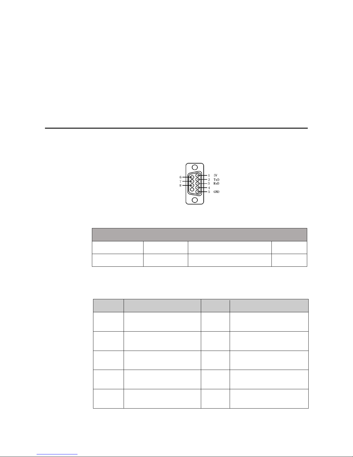
The RS-232 port of the interactive panel is defined as follows:
Connect RS-232 port to the PC or controlling device. Enable RS-233 serial port connection
and complete the following configuration.
Port: COM1 (Set according to PC or controlling device’s port number)
Bit rate 115200 Odd/even check None
Data bits 8 Stop bit 1
The following table lists button controlling codes. The buttons share same functions with
corresponding buttons on the remote controller:
Function Controlling codes Function Controlling codes
Power on
7F 08 99 A2 B3 C4 02 ff 01 00
CF
Menu
7F 08 99 A2 B3 C4 02 ff 01 1B
CF
Power off
7F 08 99 A2 B3 C4 02 ff 01 01
CF
Auto ADJ
7F 08 99 A2 B3 C4 02 ff 01 20
CF
Mute
7F 08 99 A2 B3 C4 02 ff 01 02
CF
1
7F 08 99 A2 B3 C4 02 ff 01 21
CF
Signal
source
7F 08 99 A2 B3 C4 02 ff 01 06
CF
2
7F 08 99 A2 B3 C4 02 ff 01 22
CF
Display
status
7F 08 99 A2 B3 C4 02 ff 01 09
CF
3
7F 08 99 A2 B3 C4 02 ff 01 23
CF
Page 35
35
Function Controlling codes Function Controlling codes
HD 1
7F 08 99 A2 B3 C4 02 ff 01 0A
CF
4
7F 08 99 A2 B3 C4 02 ff 01 24
CF
HD 2
7F 08 99 A2 B3 C4 02 ff 01 0B
CF
5
7F 08 99 A2 B3 C4 02 ff 01 25
CF
OPS
computer
7F 08 99 A2 B3 C4 02 ff 01 0C
CF
6
7F 08 99 A2 B3 C4 02 ff 01 26
CF
PC 1
7F 08 99 A2 B3 C4 02 ff 01 0D
CF
7
7F 08 99 A2 B3 C4 02 ff 01 27
CF
PC 2
7F 08 99 A2 B3 C4 02 ff 01 0E
CF
8
7F 08 99 A2 B3 C4 02 ff 01 28
CF
YPbPr
7F 08 99 A2 B3 C4 02 ff 01 10
CF
9
7F 08 99 A2 B3 C4 02 ff 01 29
CF
Video 1
7F 08 99 A2 B3 C4 02 ff 01 11
CF
0
7F 08 99 A2 B3 C4 02 ff 01 2A
CF
Video 2
7F 08 99 A2 B3 C4 02 ff 01 12
CF
OK
7F 08 99 A2 B3 C4 02 ff 01 2B
CF
Up
7F 08 99 A2 B3 C4 02 ff 01 13
CF
←
7F 08 99 A2 B3 C4 02 ff 01 2C
CF
Down
7F 08 99 A2 B3 C4 02 ff 01 14
CF
→
7F 08 99 A2 B3 C4 02 ff 01 2D
CF
Listen
Alone
7F 08 99 A2 B3 C4 02 ff 01 15
CF
↑
7F 08 99 A2 B3 C4 02 ff 01 2E
CF
ECO
7F 08 99 A2 B3 C4 02 ff 01 16
CF
↓
7F 08 99 A2 B3 C4 02 ff 01 2F
CF
VOL -
7F 08 99 A2 B3 C4 02 ff 01 17
CF
VOL +
7F 08 99 A2 B3 C4 02 ff 01 18
CF
Page 36
36
10 Specifications of PC Mode (VGA
Input)
SN
Standard Resolution Refresh
Rate (Hz)
Horizontal
Frequency
(Khz)
Vertical
Frequenc
y (Hz)
Horizontal/Vertic
al Sync Polarity
(TTL)
1 VESA 640X480 60 31.5 60 N/N
2 VESA 640X480 72 37.9 72 N/N
3 VESA 640X480 75 37.5 75 N/N
4 VESA 800X600 56 35.1 56 P/P
5 VESA 800X600 60 37.9 60 P/P
6 VESA 800X600 72 48.1 72 P/P
7 VESA 800X600 75 46.9 75 P/P
8 VESA 1024X768 60 48.4 60 N/N
9 VESA 1024X768 70 56.5 70 N/N
10 VESA 1024X768 75 60 75 N/N
11 VESA 1280X960 60 60 60 N/N
12 VESA 1280X960 75 75.159 75 N/N
13 VESA 1280X1024 60 64 60 P/P
14 VESA 1280X1024 75 80 75 P/P
15 VESA 1600X1200 60 75 60 P/P
16 VESA 1920X1080 60 66.547 59.988 P/P
Page 37
37
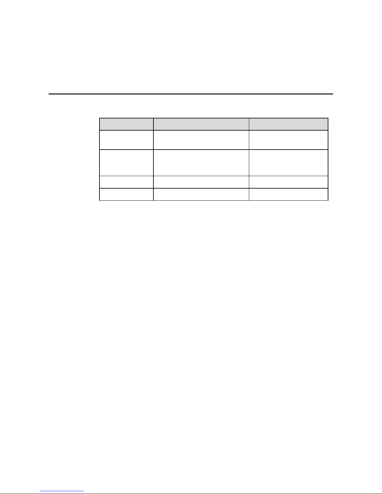
11 Formats Supported by USB Mode
Media category Formats Extension
Photo
Progressive JPEG, Baseline JPEG,
Non-Interlaced, Interlaced
.jpg, .jpeg, .bmp, .png
Movie
MPEG1, MPEG2, MPEG4, H.264,
RV8, RV9, RV10, RV8-LBR,
MJPEG, DivX, Xv i d
.avi, .mpg, .dat, .vob, .mov, .
mkv, .rm, .rmvb, .mp4, .ts, .t
rp
Music WMA, MP3, AAC .wma, .mp3, .m4a, .aac
Text TXT .txt
Page 38
38
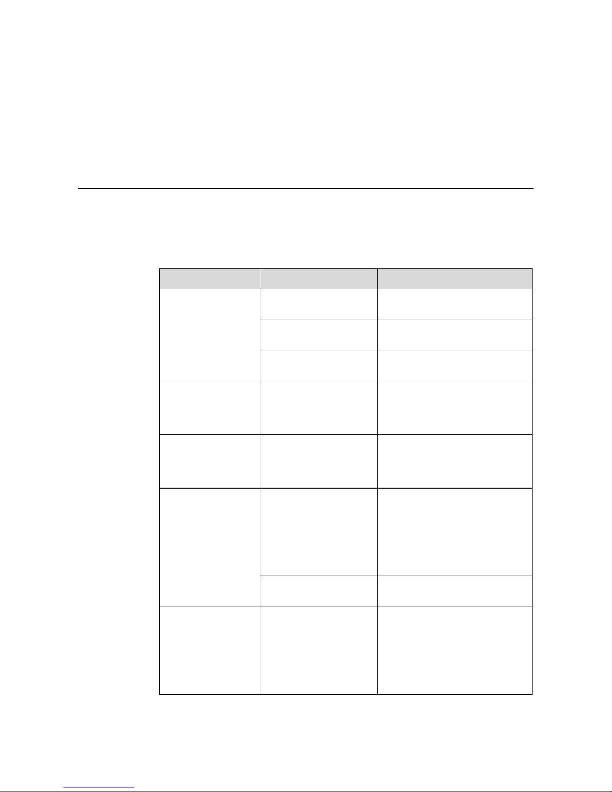
12 FAQ & Troubleshooting
Before you contact the technical support staff, please identify a fault according to the
following table. If the fault cannot be restored based on the solutions, contact the local
distributor for help. For your safety, please do not repair the product by your own.
Failure Possible Cause Solution
The service program
fails to be connected.
The drive program is not
correctly installed.
Install the drive program correctly.
The USB port (lead) is not
connected or is faulty.
Change the USB lead or check if the
USB port is faulty.
The infrared tube is
blocked.
Ensure that the surrounding infrared
tubes are not blocked.
Repositioning is
required every time
the panel is switched
on.
The computer is equipped
with a recovery card.
Disable computer protection and
perform the positioning again.
The calibration is
inaccurate. The positioning is not
performed properly.
Press AUTO on the remote
controller to show the full screen,
and use the pen provided with the
panel to perform positioning again.
The cursor of the pen
is unstable when the
pen is used.
The writing method is
incorrect.
You are advised to use the pen
rather than a finger to write. Hold
the pen as far to the nib as possible.
The angle between the pen and
display needs to be greater than 60
degrees. Do not touch the display
with your sleeve or wrist.
Strong light or infrared
interference exists.
Remove the interference source or
change the using environment.
The handwriting is
discontinuous.
The writing method is
incorrect.
You are advised to use the pen
rather than a finger to write. Hold
the pen as far to the nib as possible.
The angle between the pen and
display needs to be greater than 60
degrees. Do not touch the display
with your sleeve or wrist.
Page 39
39
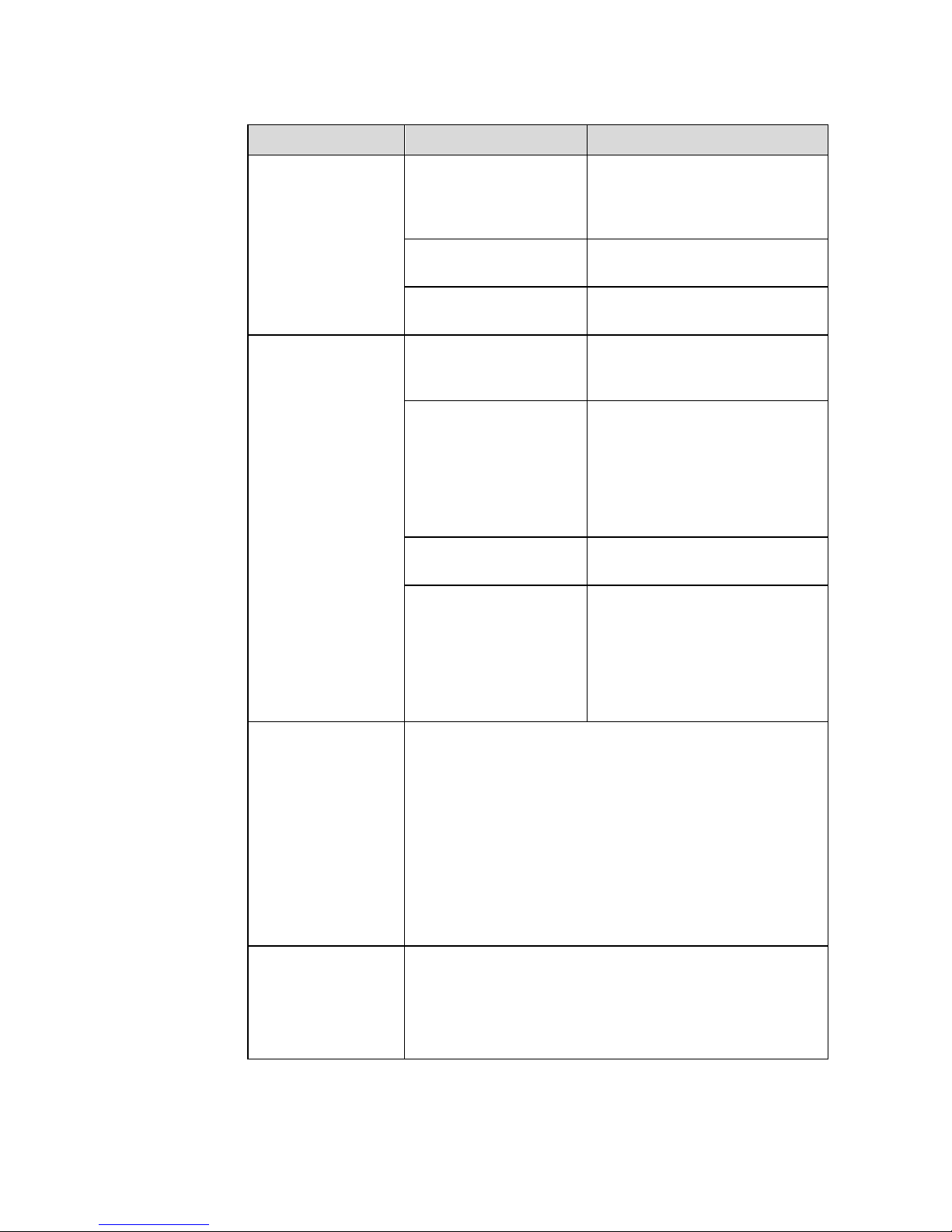
Failure Possible Cause Solution
The covering area of the
nib does not meet the
requirement or the nib is
too small.
Change the nib or use a pen with
larger covering area.
The infrared tube is
blocked.
Check if infrared tubes are blocked.
Strong light or infrared
interference exists.
Remove the interference source or
change the using environment.
Unable to write.
The color of the pen is the
same as or similar to the
background color.
Change the color of the pen.
You hand or other objects
are on the display when
you are writing.
You are advised to use the pen
rather than a finger to write. Hold
the pen as far to the nib as possible.
The angle between the pen and
display needs to be greater than 60
degrees. Do not touch the display
with your sleeve or wrist.
Strong light or infrared
interference.
Remove the interference source or
change the using environment.
The writing method is
incorrect.
You are advised to use the pen
rather than a finger to write. Hold
the pen as far to the nib as possible.
The angle between the pen and
display needs to be greater than 60
degrees. Do not touch the display
with your sleeve or wrist.
Not sound and image.
Check whether the power plug is inserted into the power socket
and whether the panel is powered on.
Check whether the rocker switch on the interactive panel is
switched on.
Check whether the standby button on the panel is pressed.
Check whether the video and audio input cables are connected
correctly.
Check whether the panel is switched to the right signal source.
Check the settings on image brightness and contrast.
Check the volume.
Image is normal, but
no sound.
Check the volume.
Check whether the MUTE button on the remote controller is
pressed.
Check whether the audio cable between the PC and interactive
panel is connected correctly.
Page 40
40
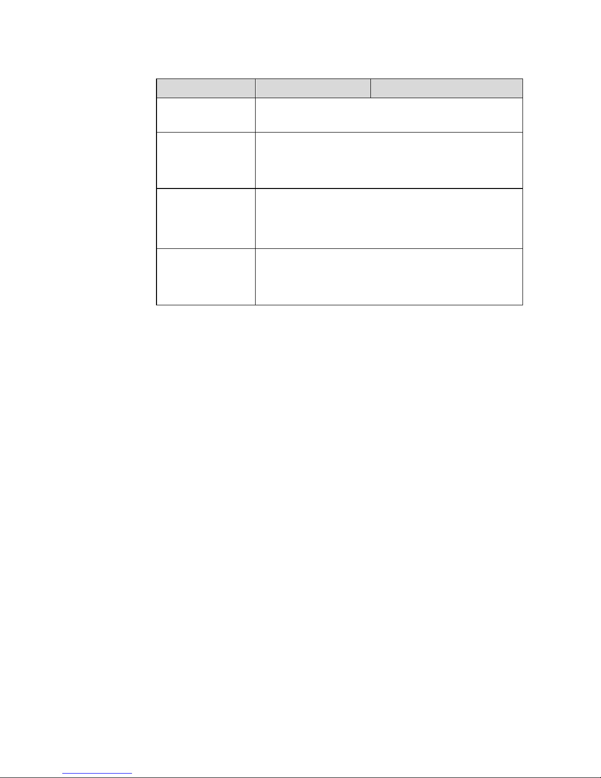
Failure Possible Cause Solution
No image or the image
is black and white.
Modify the color settings.
Check the color system.
Image or sound is
interrupted.
Find out the electric appliance that causes the interference and
move it away from the interactive panel.
Do not share the power socket of the panel with the electric
appliance that causes interference.
The remote controller
fails.
Change the batteries.
Clean the signal emitter at the top of the remote controller.
(Check whether it is blocked.)
Check contacts of the batteries.
Computer cannot be
started. (applicable for
models with
computers)
Check whether the PC adapter is correctly connected and
whether the PC is powered on.
Check whether the PC is connected correctly to the interactive
panel.
The following phenomena are not failures:
Given the high-precision production technology, the LED panel may have a very few
constantly bright or dark pixels, which turn out to be tiny red, blue, green or dark points
on the panel.
The panel may make slight sound when it is adjusting backlight or it is cooling.
When the image and sound are normal, and you touch the LED panel with fingers, you
may feel static electricity. These are normal phenomena.
Page 41

41
13 Maintenance Tips
Do not put or install the product near a heat source or under direct sunlight, in dusty or
humid places, or where the product can be affected or damaged by mechanical vibration.
To maximize the performance, it should be put away from equipment such as grid, large
metal objects and radar stations as far as possible.
Do not wipe the panel with any chemical agent. Solvents may damage the enclosure or
paint. If the panel is stained by dust, please cut off the power, soak the clean cloth in
warm water, wring it to clean the panel. You should use a clean soft cloth to clean the
LED display of the panel.
Do not frequently switch on and off the product. This can shorten the product’s service
life. After the panel is switched off, please wait for three minutes before switching on it
again. If the product is not to be used for a long period of time, please disconnect the
product from power supply.
Do not maximize the brightness and contrast of the LED display for a long period of
time, which can shorten the LED display’s service life.
Do not write on the touch screen with a hard object, which can scratch the LED display.
Page 42
42
14 Specifications
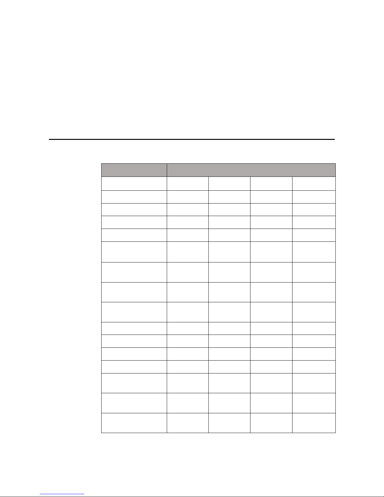
Specification Parameter
Size
55" 65" 70" 80"
Net weight 35 Kg 50 Kg 75 Kg 95 Kg
Backlight type LED LED LED LED
Aspect ratio 16:9 16:9 16:9 16:9
Viewing angle 178° 178° 178° 178°
Physical resolution
1920x1080
Pixel
1920x1080
Pixel
1920x1080
Pixel
1920x1080
Pixel
Image/Sound system
PAL, SECAM,
NTSC/DK.I
PAL, SECAM,
NTSC/DK.I
PAL, SECAM,
NTSC/DK.I
PAL, SECAM,
NTSC/DK.I
Working voltage
AC 100-240V,
50/60Hz
AC 100-240V,
50/60Hz
AC 100-240V,
50/60Hz
AC 100-240V,
50/60Hz
Touch screen material
Tempered
glass
Tempered
glass
Tempered
glass
Tempered glass
Sensing method Infrared Infrared Infrared Infrared
Technical feature HID drive-free HID drive-free HID drive-free HID drive-free
Touch point Multi-touch Multi-touch Multi-touch Multi-touch
Writing method Fingers or pen Fingers or pen Fingers or pen Fingers or pen
Resolution of touch
screen
32767x32767
32767x32767 32767x32767 32767x32767
Communication
interface
USB
USB USB USB
Storage
temperature/humidity
-20°C-60°C,
10%-90%
-20°C-60°C,
10%-90%
-20°C-60°C,
10%-90%
-20°C-60°C,
10%-90%
Page 43
43
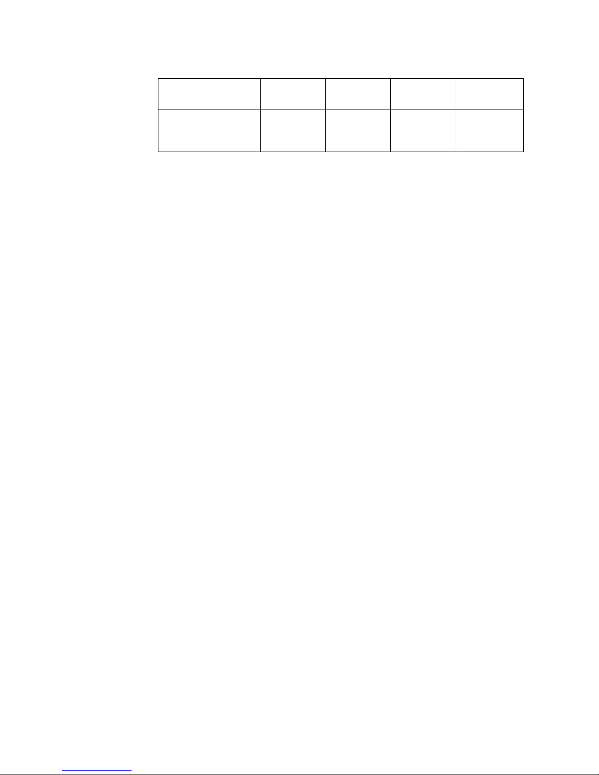
Working
temperature/humidity
0°C-40°C,
20%-80%
0°C-40°C,
20%-80%
0°C-40°C,
20%-80%
0°C-40°C,
20%-80%
Installation method
Wall or
portable
mounting
Wall or
portable
mounting
Wall or
portable
mounting
Wall or
portable
mounting
* Ligra may modify the user manual without prior notice.
* If you discover any unclear presentation, mistake or omission in this manual, please contact with us
immediately. Ligra is not liable for any loss or damage if you fail to contact with us.
 Loading...