

ligra DesignPro TENSIONED Installation Manual
Manuale d’istruzione
User manual
Manuel d’instruction
Betriebsanleitung
Manual de usuario
Articolo soggetto a modifiche senza preavviso
Subject to alteration without notice
Modifications techniques sous réserve
Technische Änderungen vorbehalten
Reservamos el derecho a realizar modificationes
DesignPro TENSIONED
L’utilizzo è consentito solo agli adulti
Operation by adults only
Utilisation pour adultes seulement
Nur von Enwachsenen zu bedienen
Solo usable para adultos
Ligra S.r.l. - Visual Communication Supplies
Via Artigiani 29/31 - 29020 Vigolzone (PC) - Italy
Tel: +39-0523.872014 Fax: +39-0523.870089
E-mail: info@ligra.it Web: www.ligra.it

!
Please open the carton and check accessories according to the list.
Adust the position between the two plates:
1.W hen assembling, do not stand in right under the screen to avoid any hazard. Expansive bolt
should be firmly punched and fixed into the wall or ceiling.
2.Be sure the ground wire is connected with power cable eectively to avoid electric shock
3.W hen use the laser pointer function on remo te control, please be sure not to point to people
directly to avoid any hurt.
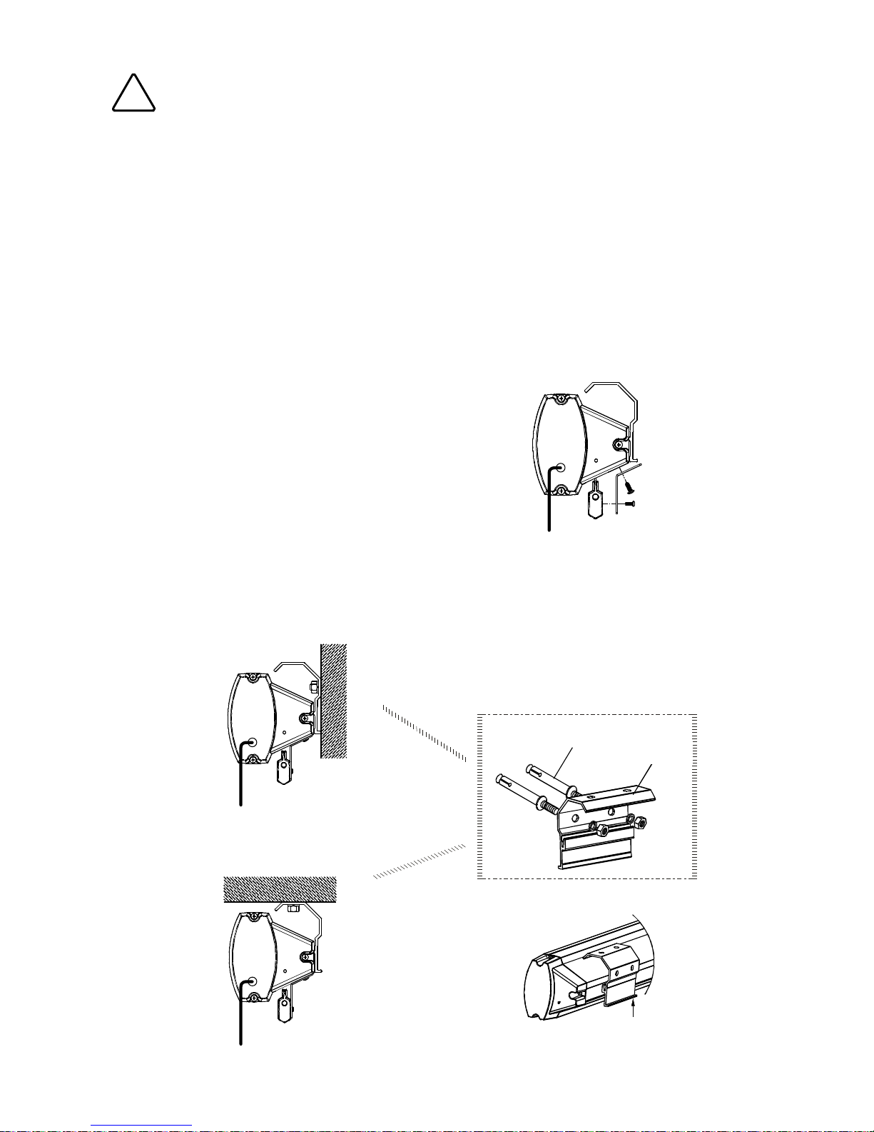
Before installing screen, please screw off the connection plate between casing and bottom bar
(Figure 1 )
Figure 1
Figure 2
Figure 3
Figure 4
Wall mounting
Expansive bolt
Assemble plate
Attenzione!
Durante il montaggio, non sostare sotto allo schermo. I tasselli devono essere ssati salda-1.
mente nel muro o nel softto.
Assicurarsi che la messa a terra ed i collegamenti elettrici siano stati effettuati correttamente.2.
Non puntare l’indicatore laser contro le persone.3.
Assemblaggio:
Aprire l’imballaggio e controllare che tutti gli accessori elencati siano presenti.
Regolare il posizionamento delle due piastre di ssaggio:
Prima di installare lo schermo, svitare la piastra presente fra il cassonetto e la barra inferiore
(gura 1)
Figura 1
Figura 2
Figura 3 Figura 4
Tassello
Placca
Metodo di montaggio suggerito:
A muro
A softto
ITALIANO
Utilizzo dello schermo con testata standard
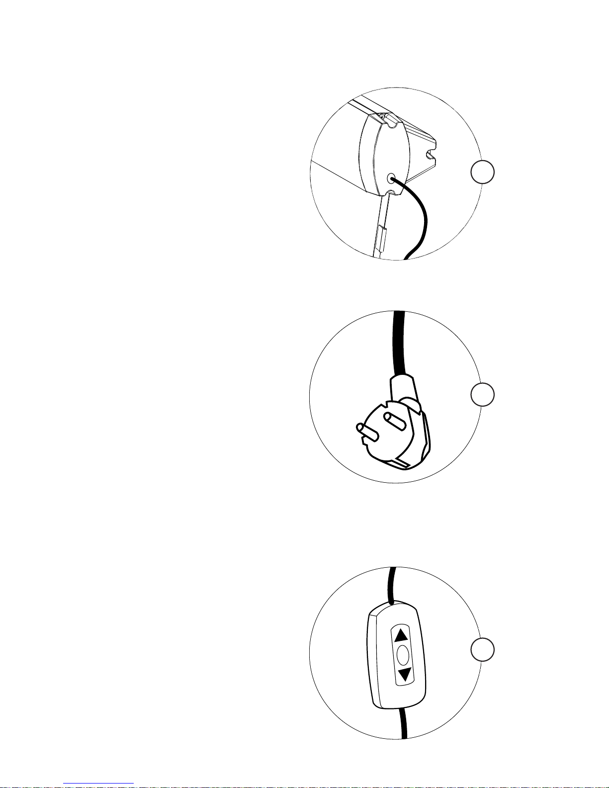
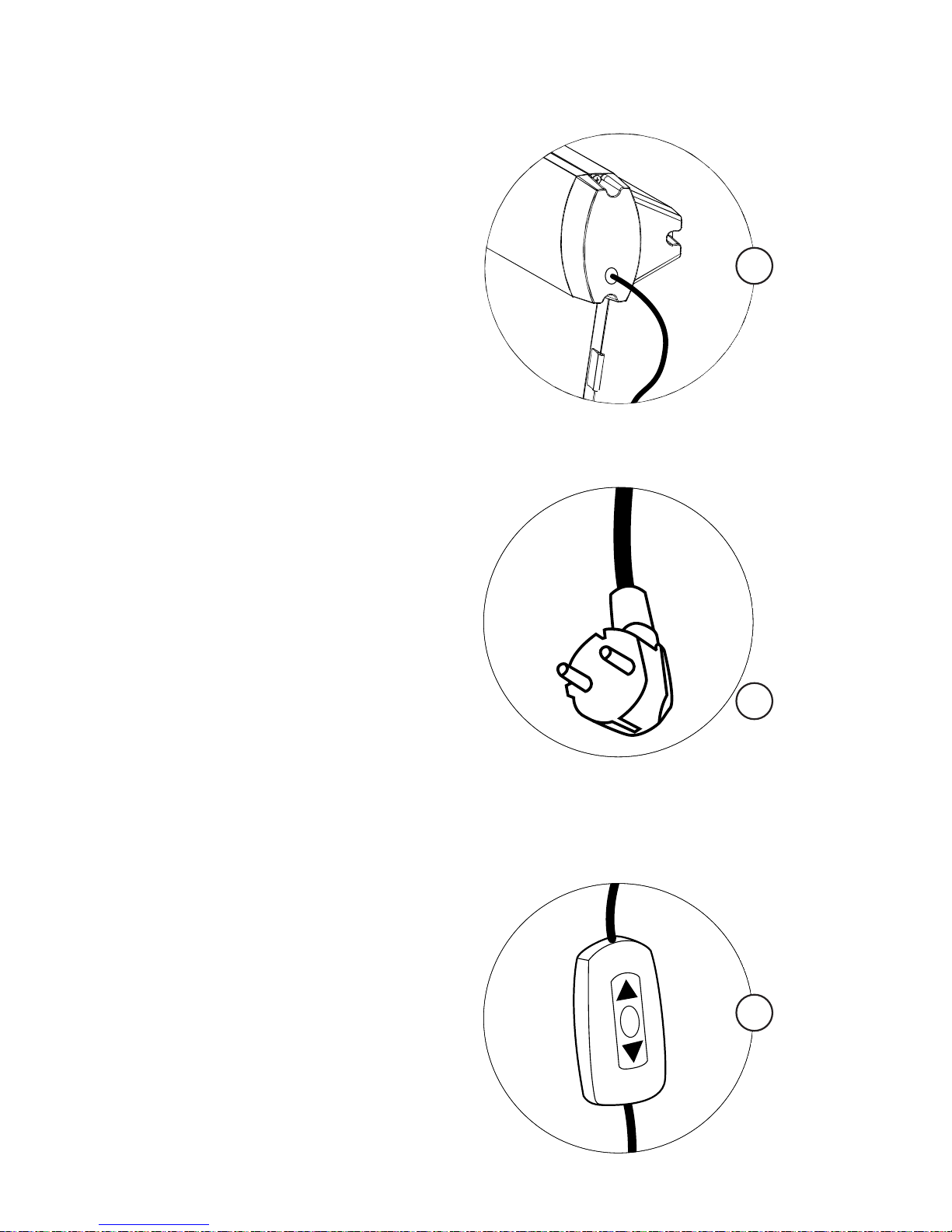
Collegare lo schermo all’alimentazione (g. 1- 2)
Utilizzare l’interruttore di controllo (g. 3)
Premere il pulsante r per sollevare lo schermo; premere il plsante s
per abbassarlo. Per fermarlo durante l’operazione, premere il pulsante O
RF remote control
o o
1.
RF remote control
o o
2.
RF remote control
o o
3.
ITALIANO

1.Plug the power cord into the power jack on the right end cap.
2.Switch on the power (within stated voltage)
1.Insert manual switch cord into the interface of right end cap
Push the button down, lift the screen
Push the button up to down the screen
To stop any time while the screen is in motion,
turn the button to o""
2.Connect power on
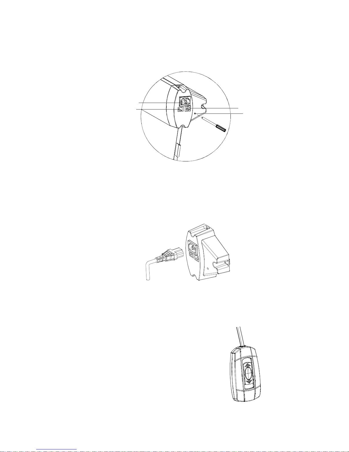
The screen provide four control ways:;
cordless trigger control; manual switch contr l; RS485 contr l (Figure 5)
RF remote control
oo
Power Cord Jack AC 90~240V
Manual Switch Interface
RS485 Interface
Learn Code Hole
Figure5
Figure6
Figure7
Utilizzo della testata opzionale
Lo schermo può essere controllato in quattro modi diversi: con l’interruttore manuale, con il
radiocomando, con il telecomando, con il comando RS485 (gura 5)
Collegare lo schermo all’alimentazione:
Collegare l’alimentatore al jack di alimentazione sull’estremità destra del cassonetto1.
Accendere l’alimentazione (col voltaggio indicato)2.
Figura 5
Figura 6
Jack di alimentazione AC90 - 240V
Interfaccia RS485
Interfaccia interruttore manuale
Foro di programmazione
Interruttore di controllo:
Collegare l’interruttore manuale di controllo alla presa 1.
sull’estremità destra del cassonetto
Premere il pulsante 2. r per sollevare lo schermo; premere il
plsante s per abbassarlo. Per fermarlo durante l’operazione,
premere il pulsante O
ITALIANO
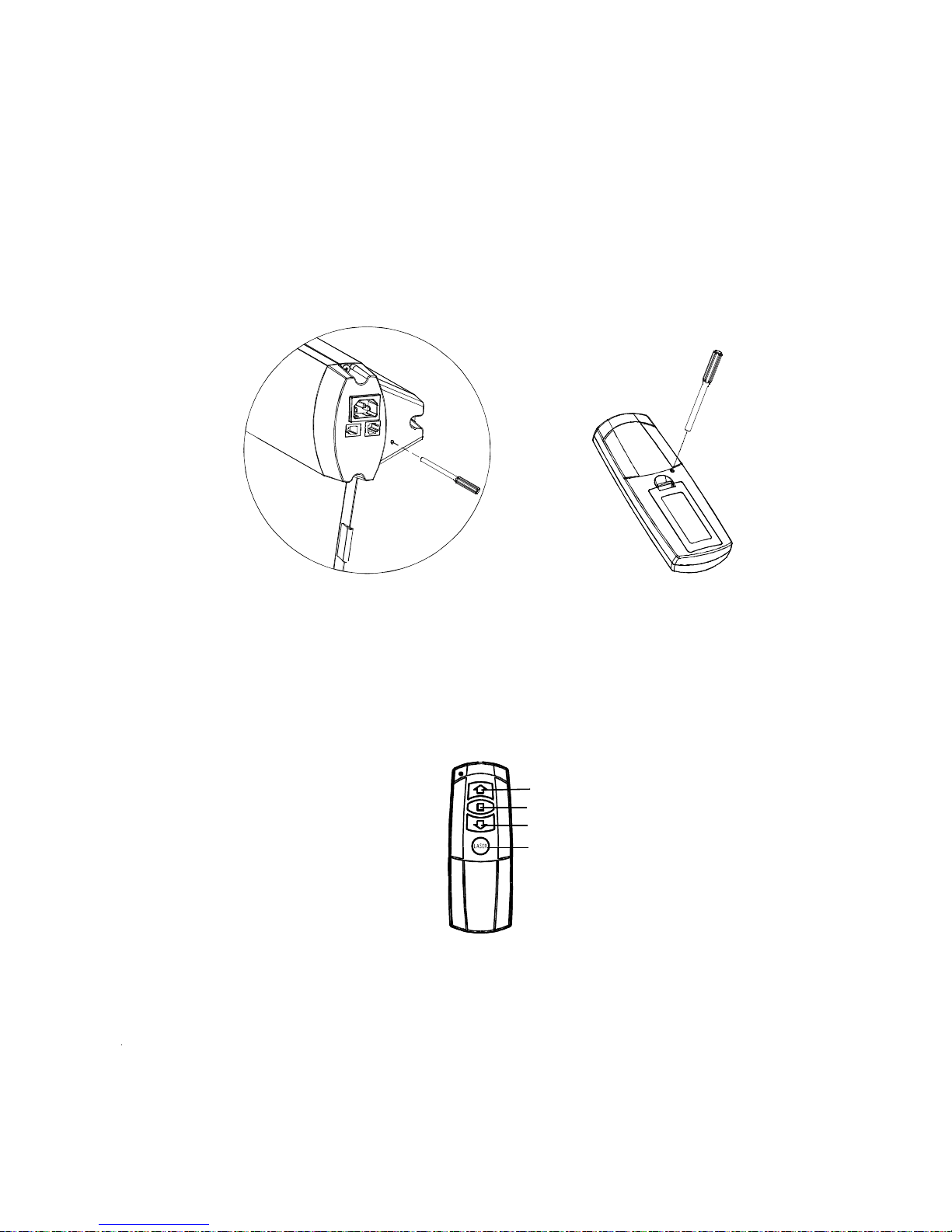
1.The remote has been set up at the factory,and should work right away. However, if you would like
to control another screen with the same control, you will need to use the learn function.
2.Make sure the manual switch is in the closed position and the switch- cord disconnected. Please press
the hole at the right-end-cap for 3 seconds, indicated by a light flash, then press the back of remote
control the receiver led light at the right-end-cap will become normally on from flash situation. Now we
finish the learn
code function . Please refer to remote control user manul for some details instruction
about learn code function
The remote uses a powerful anti-interference module, providing excellent stability. By using the screens
built-in-receiver, the screen can be controlled from as far away as 40 meters (wall will reduce the distance)
3.Please operate as follows
Figure8
Figure9
Up
Stop
Down
Laser pointer button
Remote control
(Battery AAA DC 1.5V 2)
Figura 8
Figura 9
Radiocomando RF 868 MHZ:
Il radiocomando è impostato alla fabbricazione, e dovrebbe funzionare senza bisogno di nessun tipo di
programmazione. Comunque, nel caso voleste controllare un altro schermo con lo stesso radiocomando,
dovrete seguire questa procedura:
Assicurarsi che l’interruttore manuale sia in posizione di chiusura ed il cavo scollegato. Premete il foro di
programmazione per circa 3 secondi (la spia luminosa inizia a lampeggiare), poi premete il foro di programmazione sul retro del radiocomando nché la spia cesserà di lampeggiare.
Il radiocomando funziona come segue:
Alza
Stop
Abbassa
Indicatore laser
Premere r per alzare lo schermo
Premere p per fermare lo schermo
Premere s per abbassare lo schermo
Radiocomando
(Pile AAA DC 1.5V x 2)
Il radiocomando utilizza un efcace sistema anti-interferenza, che gli conferisce un’ottima afdabilità.
utilizzando il ricevitore incorporato nello schermo, quest’ultimo può essere controllato da 40 metri di
distanza (ostacoli in muratura potrebbero accorciare tale distanza).
ITALIANO
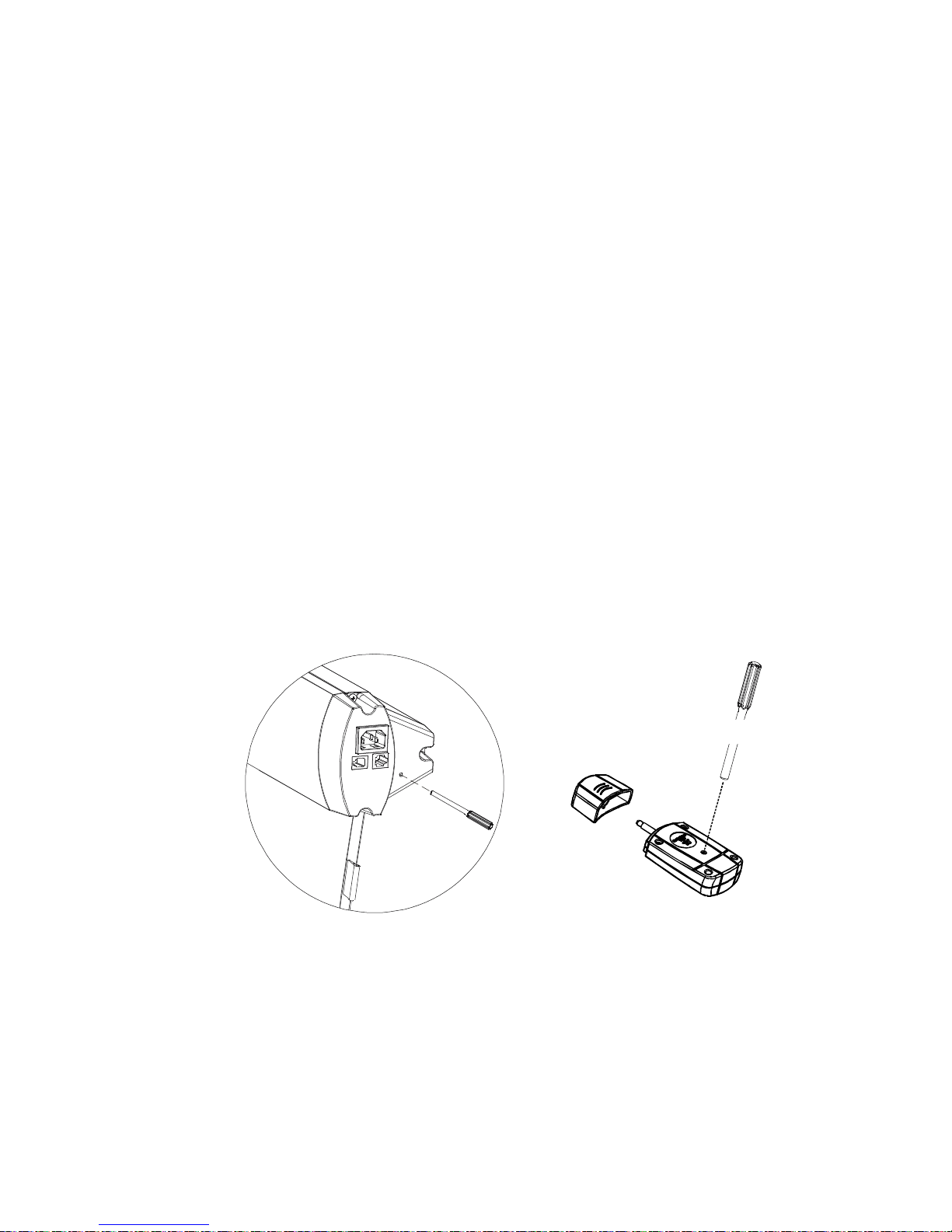
1.
2.Insert the trigger directly into trigger out interface of projector,
when running the projector, the screen will down automatically
when closing the projector , the screen will up automatically
Make sure the manual switch is in the closed position and the switch- cord disconnected
1. Also make sure
your projector open trigger function. press the hole of right end cap3seconds with small touch
needle, indicated by a light flash, then press the hole in the back of cordless trigger 3 seconds, receiver
led light at the right-end-cap will become normally on from flash situation.. Now we finish the learn code
function.
Make sure the manual switch is in the closed position and the switch- cord disconnected
Please refer to cordless trigger control user manul for some details instruction about learn code
fu
nction.
Plug one side of the signal cord into the computer output interface at right side of the s end
cap, the other side of the signal cord to plug into the interface of computer Rs485, and then you
can run the screen up/pause/down via computer.
creen's
The remote has been set up at the factory,and should work right away. Please operate as follows:
If need control another screen with the same trigger,or changed new remote control than need finish learn
code again as follows.
After finishing learn code function, now, you can insert p
rojector trigger out interface straightly. Our
patented cordless trigger allows your screen synchronize its up and down with projector power cycle.
When projector power open, the screen up ,projector power close, the screen down automatically. Or
when projector power is open situation, you insert wireless trigger, the screen will up, take the trigger
off projector, the screen will also down automatically.
Figure 10
Telecomando DC 3-12V:
Il comando è impostato alla fabbricazione, e dovrebbe funzionare senza bisogno di nessun tipo di
programmazione. Utilizzatelo come segue:
Assicuratevi che l’interruttore manuale sia in posizione di chiusura e che il cavo sia scollegato.
Inserite l’interruttore direttamente nella presa corrispondente sul proiettore. Accendendo il proiettore, lo schermo scenderà automaticamente; spegnendo il proiettore, lo schermo si alzerà automaticamente.
Se volete controllare un altro schermo con lo stesso interruttore o cambiare il vostro interruttore,
dovrete procedere come segue:
Assicurarsi che l’interruttore manuale sia in posizione di chiusura ed il cavo scollegato. Premete il
foro di programmazione per circa 3 secondi (la spia luminosa inizia a lampeggiare), poi premete il
foro di programmazione sul retro del radiocomando nché la spia cesserà di lampeggiare.
Dopo aver completato la procedura potete inserire direttamente l’interruttore nella presa corrispondente del proiettore. Il nostro interruttore vi permette di sincronizzare i movimenti dello schermo
con l’accensione e lo spegnimento del proiettore: quando si accende il proiettore lo schermo scende; quando lo si spegne, sale automaticamente.
Figura 10
Figura 9
Comando RS 485:
Inserite un capo del cavo di collegamento nella porta corrispondente del vostro computer, e l’altro
capo alla porta posta sull’estremità destra del cassonetto: in questo modo, con il comando RS 485,
potrete controllare i movimenti dello schermo tramite il vostro computer.
ITALIANO
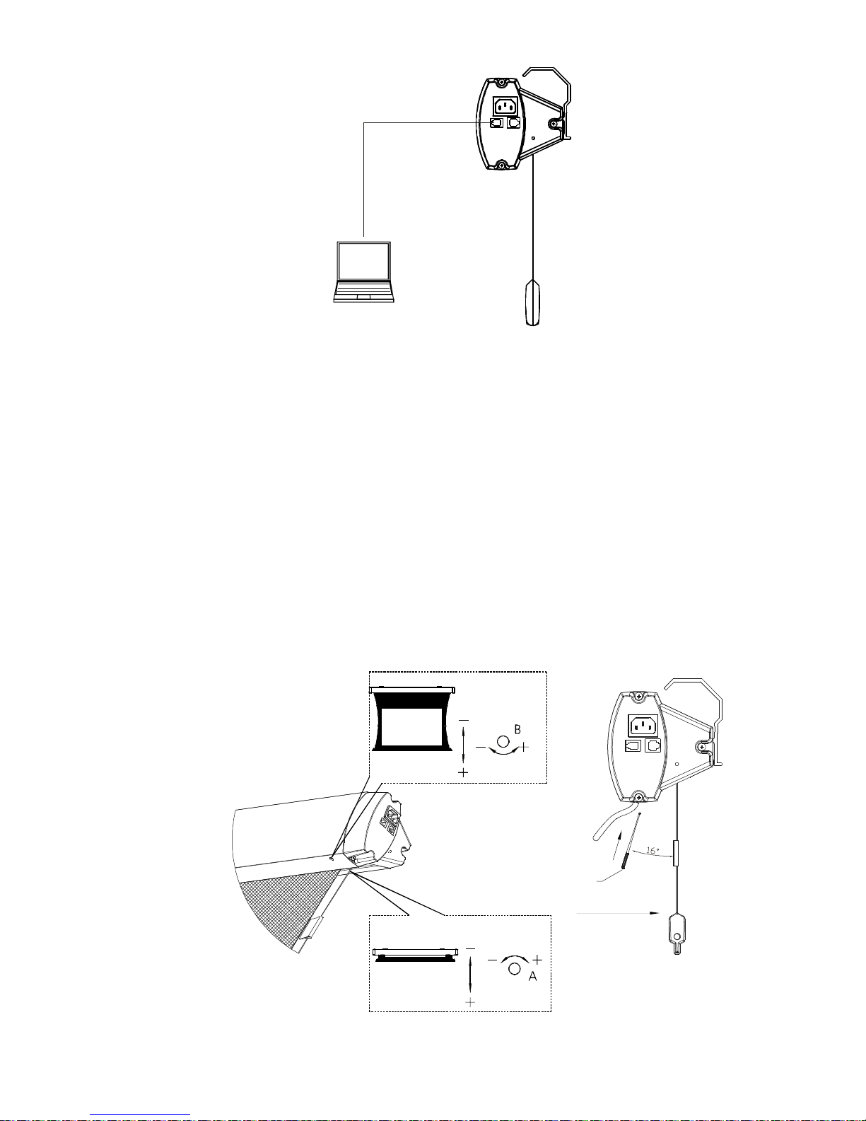
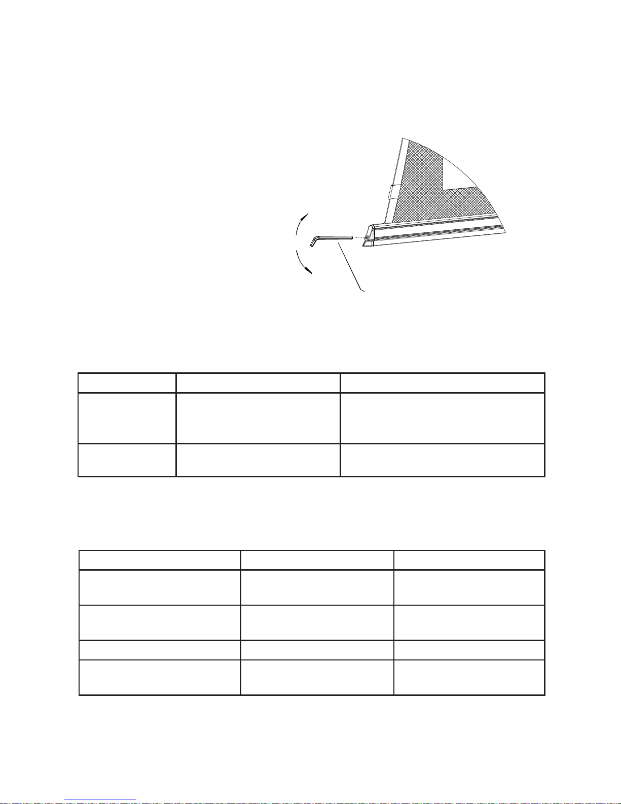
Fabric is always on the right position before out of factory. However, If fabric needs adjusting, a micro
adjusting switch is provided. Please useascrew knife of 3mm diameter or other enclosed tool to insert
into the hole the right bottom of case for adjusting
1. Adjusting for up limited position (fabric drawing back stage)When the fabric in the stage of drawing
back and the bottom shaft is not in right place, please operate as the up limited position drawing, turn
as direction, the fabric will descend; turn as direct
ion, the fabric will rise.+" " " -"
Note: please insert the tool as the showed angle.
2.Adjusting for bottom limited position (fabric completely open up) when the fabric completely
open up, while the top black border is not in right place .please operate as the bottom limited
position drawing ,turn as direction, the fabric will descend; turn as direction, the
fabric will rise.
+" " " -"
Figure 11
Figure 12
Adjusting tool
Front side
Up limited adjusting
Bottom limited
adjusting
Figura 11
Figura 12
Regolazione della tela:
La tela viene sempre posizionata in modo corretto direttamente in fabbrica. Comunque, nel caso in
cui fosse necessario regolarla, è possibile operare piccole correzioni. Inserite nell’apposito foro un
cacciavite di diametro 3mm o la chiave fornita nella confezione, operando sulla vite.
Regolazione ne corsa superiore: se lo schermo non si ritrae completamente all’interno del cassonetto, ruotate la vite in senso antiorario per far scendere la tela o in senso orario per farla salire.
Regolazione ne corsa inferiore: se lo schermo non scende completamente, ruotate la vite in
senso antiorario per far scendere la tela o in senso orario per farla salire.
NB: Inserite il cacciavite o l’attrezzo apposito con l’angolo mostrato nella gura 12.
Regolazione ne
corsa inferiore
Regolazione ne corsa superiore
Cacciavite / Chiave
Lato frontale
ITALIANO
If the tension is loose or over-tension, please adjust is as following fig
Tighten
Tool
Insert
Loose
Figure 13
Regolazione del tensionamento:
Se il tensionamento è eccessivo o insufciente, regolatelo come segue:
Figura 13
Inserire
Stringere
Allentare
Chiave
Manutenzione:
Malfunzionamenti:
Se si vericassero altri malfunzionamenti consultate il vostro rivenditore.
Malfunzionamento Controllo da effettuare Soluzione
Il radiocomando non
funziona
Vericare la carica della
pila
Sostituire la pila
Il motore è rumoroso Il condensatore è guasto Sostituire il condensa-
tore
Il motore non funziona Il motore è guasto Sostituire il motore
La tela non si riavvolge
correttamente
Vericare il ne corsa
della tela
Regolare il ne corsa
della tela come indicato
Area Polvere Sporco
Cassonetto Usare un comune piumino Pulire con una soluzione di
sapone delicato ed un panno di
cotone. Non grafare la supercie
Schermo Usare un comune piumino Usare un panno di cotone
ITALIANO
1.Please do not run the screen continuously above 5minutes to avoid the motor damaged due to
overheat aging; when next operation please wait the motor cool down
2.Do not scratch or fold up the fabric.
3.Afer usage, please check again there are no other foreign objectives on the screen surface and
then draw back the fabric into the case
Screen learn needle
Trigger learn needle
Cordless rigger
Remote control
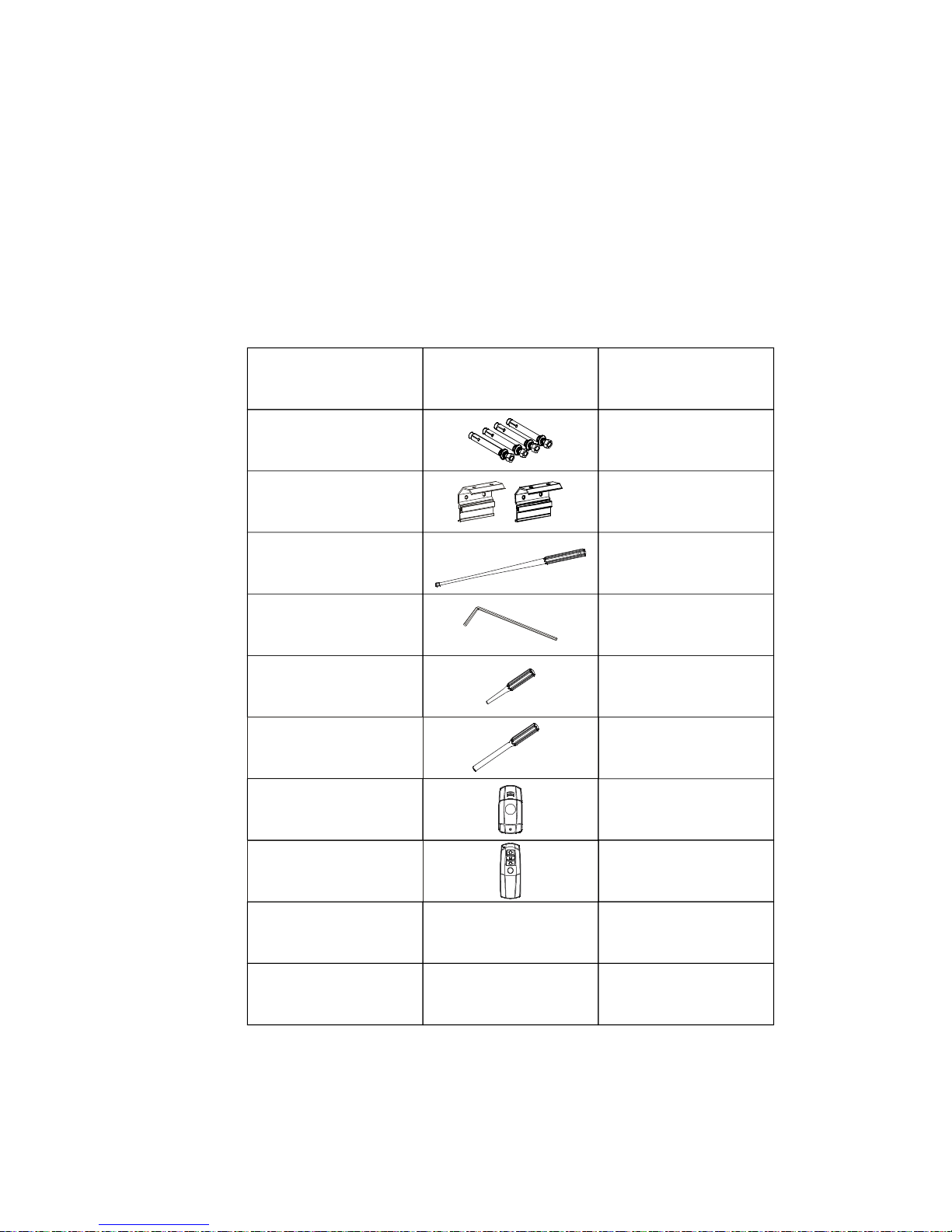
Quantity
LASER
Picture
Name
Hex key
Adjusting tool
Assembling plate
Expansive bolt
1
1
1
1
1
1
2
4
Power cord
2m(standard)
5m(optional)
RS485 cord
5m
Ricordate:
Non azionate lo schermo per più di 5 minuti consecutivi, dal momento che il surriscaldamento 1.
conseguente potrebbe danneggiare il motore; prima di procedere lasciatelo raffreddare.
Non grafare o piegare la tela.2.
Dopo l’utilizzo, prima di riavvolgere la tela controllate che non ci siano corpi estranei sulla sua 3.
supercie.
Accessori:
Nome
Tassello
Piastra di ssaggio
Chiave di regolazione
Chiave esagonale
Radiocomando
Telecomando
Cavo di alimentazione
Cavo RS 485
Riprogrammazione
radiocomando
Riprogrammazione
schermo
Immagine Quantità
ITALIANO
!
Please open the carton and check accessories according to the list.
Adust the position between the two plates:
1.W hen assembling, do not stand in right under the screen to avoid any hazard. Expansive bolt
should be firmly punched and fixed into the wall or ceiling.
2.Be sure the ground wire is connected with power cable eectively to avoid electric shock
3.W hen use the laser pointer function on remo te control, please be sure not to point to people
directly to avoid any hurt.
Before installing screen, please screw off the connection plate between casing and bottom bar
(Figure 1 )
Figure 1
Figure 2
Figure 3
Figure 4
Wall mounting
Expansive bolt
Assemble plate
Attention!
When assembling, do not stand under the screen to avoid any hazard. Expansive bolt should 1.
be rmly xed into the wall or ceiling.
Be sure the ground wire is properly connected with power cable 2.
Do not point the laser pointer to people .3.
ASSEMBLY
Open the packing and check accessories according to the list.
Adjust the position between the two xing plates:
Before installing the screen, screw off the connection plate between the screen case and the
bottom bar
(Figure 1 )
Figure 1
Figure 2
Figure 3 Figure 4
Expansive bolt
Assembly plate
Suggested assembly procedure
Wall mounting
Ceiling mounting
ENGLISH
Use of the standard screen case
Plug in the screen power cord (Figures 1-2)
Use of the MANUAL CONTROL SWITCH (Figure 3)
Push the button ▲up to lift the screen
Push the button ▼ down to lower the screen
To stop it any time push the button ●
RF remote control
o o
1.
RF remote control
o o
2.
RF remote control
o o
3.
ENGLISH
1.Plug the power cord into the power jack on the right end cap.
2.Switch on the power (within stated voltage)
1.Insert manual switch cord into the interface of right end cap
Push the button down, lift the screen
Push the button up to down the screen
To stop any time while the screen is in motion,
turn the button to o""
2.Connect power on
The screen provide four control ways:;
cordless trigger control; manual switch contr l; RS485 contr l (Figure 5)
RF remote control
oo
Power Cord Jack AC 90~240V
Manual Switch Interface
RS485 Interface
Learn Code Hole
Figure5
Figure6
Figure7
Use of the optional screen case
The screen provides four different control types: manual control switch, radio control, trigger,
RS485 control (Figure 5)
Plug in the screen power cord:
Plug in the power plug to the power slot on the right side of the screen case.1.
Turn on the power (at the indicated voltage) 2.
Figure 5
Figure 6
Figure 7
Power Cord Jack AC 90~240V
RS485 Interface
Manual Switch Interface
Setting hole
MANUAL CONTROL SWITCH:
Den Handschalter an die rechten Seite des Leinwands 1.
einstecken
Push the button ▲up to lift the screen Push the button 2.
▼ down to lower the screen To stop it any time push the
button ●
ENGLISH

1.The remote has been set up at the factory, and should work right away. However, if you would like
to control another screen with the same control, you will need to use the learn function.
2.Make sure the manual switch is in the closed position and the switch- cord disconnected. Please press
the hole at the right-end-cap for 3 seconds, indicated by a light flash, then press the back of remote
control the receiver led light at the right-end-cap will become normally on from flash situation. Now we
finish the learn
code function . Please refer to remote control user manul for some details instruction
about learn code function
The remote uses a powerful anti-interference module, providing excellent stability. By using the screens
built-in-receiver, the screen can be controlled from as far away as 40 meters (wall will reduce the distance)
3.Please operate as follows
Figure8
Figure9
Up
Stop
Down
Laser pointer button
Remote control
(Battery AAA DC 1.5V 2)
Figure 8
Figure 9
RADIO CONTROL RF 868 MHZ
The radio control has been set up at the factory and it should work right away without any further setting.
However, if you would like to control another screen with the same radio control, please follow this proce-
dure:
Make sure the manual switch is in the closed position and the switch- cord disconnected. Press
the setting hole for 3 seconds, (led light will ash), then press the setting hole on the back of the radio
control till the led light will stop ashing.
How to operate the radio control:
UP
STOP
DOWN
LASER POINTER BUTTON
Push the button ▲up to lift the screen
To stop it any time push the button ■
Push the button ▼ down to lower the screen
RADIO CONTROL
(Battery AAA DC 1,5v X 2)
The RADIO CONTROL uses a powerful anti-interference module, providing excellent stability. By using
the screens built-in-receiver, the screen can be controlled from as far as 40 meters (walls in-betweens
might reduce the distance)
ENGLISH
 Loading...