


LigoPTP software
User’s Guide
Model No.: FWBD1401
Brand Name:LigoWave
Revision 1.4
January 27, 2015
Copyright © 2005-2010LigoWavewww.ligowave.com
LigoWave Page 1

第十二條
經型式認證合格之低功率射頻電機,非經許
可,公司、商號或使用者均不得擅自變更頻
率、加大功率或變更原設計之特性及功能。
第十四條
低功率射頻電機之使用不得影響飛航安全及
干擾合法通信;經發現有干擾現象時,應立
即停用,並改善至無干擾時方得繼續使用。
前項合法通信,指依電信法規定作業之無線
電通信。
低功率射頻電機須忍受合法通信或工業、科
學及醫療用電波輻射性電機設備之干擾。
NCC Statement:
根據 NCC 低功率電波輻射性電機管理辦法規定:
LigoWave Page 2

FCC Warning
This device complies with part 15 of the FCC Rules.
Operation is subject to the following two conditions: (1)
This device may not cause harmful interference, and (2)
this device must accept any interference received,
including interference that may cause undesired
operation.
Changes or modifications not expressly approved by the
party responsible for compliance could void the user's
authority to operate the equipment.
FCC Radiation Exposure Statement
The modular must be professional installed as fixed point-
to-point access points only.
This modular complies with FCC RF radiation exposure
limits set forth for an uncontrolled environment. This
transmitter must not be co-located or operating in
conjunction with any other antenna or transmitter. This
modular must be installed and operated with a minimum
distance of 271.3 cm between the radiator and user body.
If the FCC identification number is not visible when the
module is installed inside another device, then the outside
of the device into which the module is installed must also
display a label referring to the enclosed module. This
exterior label can use wording such as the following:
“Contains Transmitter Module FCC ID: V2VFWBD1401V2 Or Contains FCC ID: V2VFWBD1401V2”
when the module is installed inside another device, the
user manual of this device must contain below warning
statements;
1. This device complies with Part 15 of the FCC Rules.
Operation is subject to the following two conditions:
(1) This device may not cause harmful interference.
(2) This device must accept any interference received,
including interference that may cause undesired
operation.
2. Changes or modifications not expressly approved by
the party responsible for compliance could void the user's
authority to operate the equipment.
The devices must be installed and used in strict
accordance with the manufacturer's instructions as
described in the user documentation that comes with the
product
CE Mark Warning
This is a Class A product. In a domestic
environment this product may cause radio
interference in which case the user may be required
to take adequate measures.
R&TTE Compliance
Statement
This equipment complies with all the requirements
of the Directive 1999/5/EC of the European
Parliament and the Council of 9 March 1999 on
Radio Equipment and Telecommunication
Terminal Equipment and the Mutual Recognition
of their Conformity (R&TTE). The R&TTE
Directive repeals and replaces in the directive
98/13/EEC (Telecommunications Terminal
Equipment and Satellite Earth Station Equipment)
As of April 8, 2000.
Safety
This equipment is designed with the utmost care
for the safety of those who install and use it.
However, special attention must be paid to the
dangers of electric shock and static electricity
when working with electrical equipment. All
guidelines of this manual and of the computer
manufacturer must therefore be allowed at all times
to ensure the safe use of the equipment.
EU Countries Intended for Use
The ETSI version of this device is intended for
home and office use in Austria, Belgium,
Denmark, Finland, France (with Frequency
channel restrictions), Germany, Greece, Ireland,
Italy, Luxembourg, The Netherlands, Portugal,
Spain, Sweden and United Kingdom. The ETSI
version of this device is also authorized for use in
EFTA member states Iceland, Liechtenstein,
Norway and Switzerland.
EU Countries Not Intended for
Use
None.
LigoWave Page 3

FCC Caution
To assure continued compliance, any changes or
modifications not expressly approved by the party
responsible for compliance could void the user's authority
to operate this equipment.
FCC Radiation Exposure
Statement
To comply with FCC RF exposure requirements in
section 1.1307, a minimum separation distance of 8.7 feet
is required between the antenna and all public persons.
LigoWave Page 4

Contents
FCC Warning ....................................................................................................................................... 3
FCC Caution ............................................................................................................................................... 4
FCC Radiation Exposure Statement ........................................................................................................... 4
CE Mark Warning ................................................................................................................................ 3
R&TTE Compliance Statement ........................................................................................................... 3
Safety .......................................................................................................................................................... 3
EU Countries Intended for Use ................................................................................................................... 3
EU Countries Not Intended for Use ............................................................................................................. 3
CONTENTS ............................................................................................................................................ 5
ABOUT THIS GUIDE .............................................................................................................................. 7
Purpose ............................................................................................................................................... 7
Definitions, Acronyms and Abbreviations ............................................................................................ 7
INTRODUCTION ..................................................................................................................................... 8
Application Examples .......................................................................................................................... 9
Building to Building Connectivity...................................................................................................... 9
Backhaul .......................................................................................................................................... 9
PTP Features .................................................................................................................................... 10
Technical Features .................................................................................................................................... 10
Management ............................................................................................................................................. 10
Reliability ................................................................................................................................................... 10
ACCESSING THE PTP UNIT’S WEB MANAGEMENT ....................................................................... 11
Default Settings ............................................................................................................................. 12
Quick Setup Guide ............................................................................................................................ 12
Verify PTP Link Connection .............................................................................................................. 16
Align Antenna .................................................................................................................................... 20
WEB MANAGEMENT ........................................................................................................................... 21
General Operation ............................................................................................................................. 21
Instant Changes ............................................................................................................................. 21
System Warnings and Errors ......................................................................................................... 21
Signal Indicator .............................................................................................................................. 22
Status ................................................................................................................................................ 24
System ........................................................................................................................................... 24
Network .......................................................................................................................................... 25
Wireless ......................................................................................................................................... 25
Statistics ......................................................................................................................................... 26
Graphs ........................................................................................................................................... 27
Configuration ..................................................................................................................................... 31
Network .......................................................................................................................................... 31
Radio .............................................................................................................................................. 32
Instant Changes ........................................................................................................................................ 32
System ........................................................................................................................................... 34
Link Settings .............................................................................................................................................. 34
System Date .............................................................................................................................................. 34
Administrative Account .............................................................................................................................. 36
System Log ............................................................................................................................................... 36
Services ......................................................................................................................................... 37
SNMP Configuration ................................................................................................................................. 37
WNMS Configuration ................................................................................................................................ 38
LigoWave Page 5

System Alerts ............................................................................................................................................ 38
Maintenance .............................................................................................................................................. 40
System Functions ...................................................................................................................................... 40
OLED Control ............................................................................................................................................ 41
Firmware Upgrade .................................................................................................................................... 42
Tools .................................................................................................................................................. 43
Antenna Alignment ........................................................................................................................ 43
Site Survey ..................................................................................................................................... 43
Link Test ........................................................................................................................................ 44
Logout ................................................................................................................................................ 46
APPENDIX ............................................................................................................................................ 47
A) Run PTP Link in Small Distance ................................................................................................... 47
B) Resetting Unit to Factory Defaults ................................................................................................ 50
LigoWave Page 6

Additional information that may be helpful but which is not required.
Important information that should be observed.
bold
Menu commands, buttons, input fields, links, and configuration keys are displayed in bold
italic
References to sections inside the document are displayed in italic.
code
File names, directory names, form names, system-generated output, and user typed
entries are displayed in constant-width type
About This Guide
Purpose
This document provides information and procedures on installation, setup, configuration, and
management of the PTP unit.
Definitions, Acronyms and Abbreviations
The following typographic conventions and symbols are used throughout this document:
LigoWave Page 7

Introduction
The PTP link consists of two units, one on each end: Master and Slave. Master unit operates as an
access point; therefore the Slave connects to the Master and operates as a client.
Figure 1 – Point-to-Point Link Elements
From the point of view of the administrator the Local unit is the one with the direct connection to the
Web management interfaceand the Remote unit is the one which is connected to the Local unit in
PTP link. The concept of the Local unit and the Remote unit is not related to the operating mode
(Master or Slave). This terminology will be used throughout the manual, particularly in the description
of statistics.
LigoWave Page 8

Application Examples
Building to Building Connectivity
Use the PTP for building to building connectivity in the private networks such as campus building
connections, corporate building connections, universities and schools that wish to own and manage
their own networks and eliminate the costly recurring charges from service providers. The same
connectivity is perfect to build backup/failover connections.
Figure 2 – Building to Building Connectivity
Backhaul
The PTP offers a cost effective solution made for WISPs, Cellular Carrier, Telco, ISPs, enabling
operators to quickly and efficiently expand their networks.
Figure 3 – PTP Backhaul
LigoWave Page 9
PTP Features
Technical Features
High throughput;
Flexible Channel Sizes (20MHz and 40MHz);
Flexible center frequency selection (allows selecting center frequency in 5MHz step);
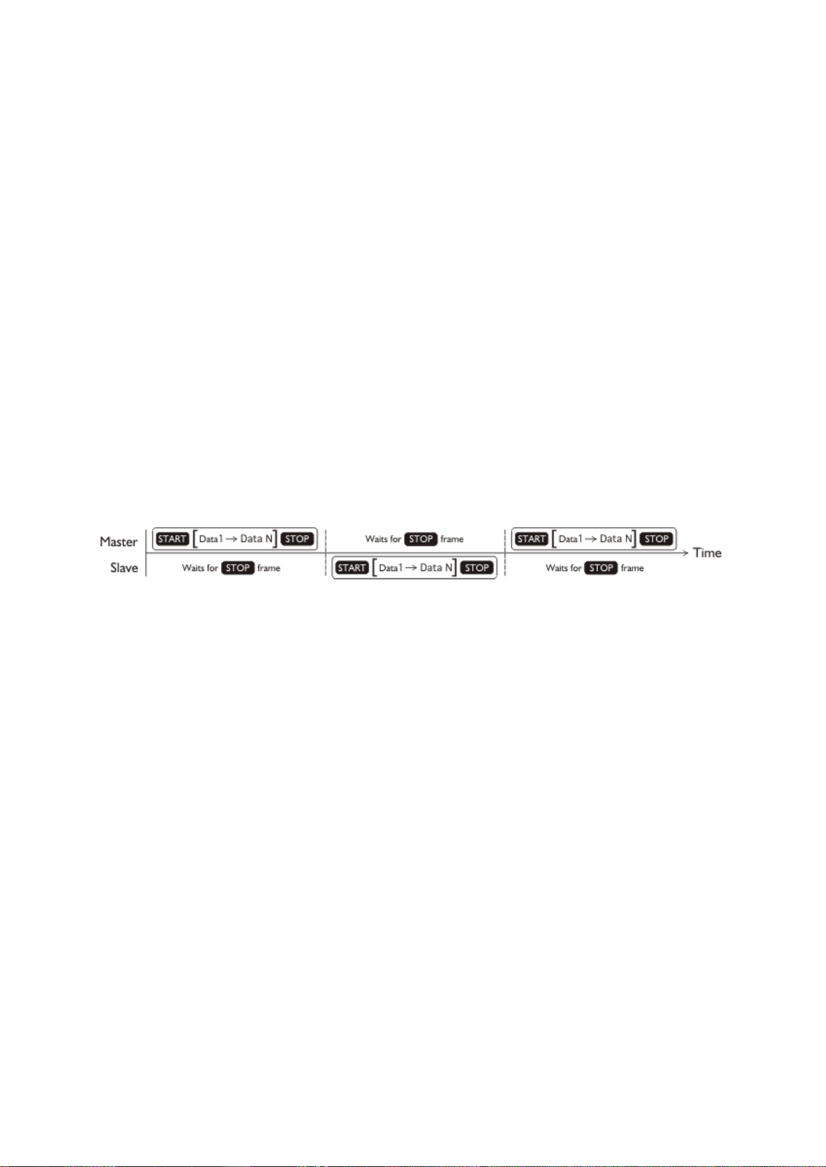
Robust MAC layer:
Selective repeat ARQ with block ACK
Only lost packets are retransmitted
Highly efficient in noisy environments
Low throughput loss over long distance
Forward error correction (recovers packets with errors without retransmit)
Dynamic TDD (see theFigure 4 – Point to Point Protocol W-jet MIMO)
Allocates bandwidth in the direction needed in real-time
Highly reliable and efficient over long distances
Packet aggregation (smaller frames are collected into larger frames to increase efficiency and
throughput)
High PPS (Packet Per Seconds) performance
High TX power and RX Sensitivity
PoE built-in for single cable installation
Figure 4 – Point to Point Protocol W-jet MIMO
Management
Flex based fast GUI
Command line management via SSH
WNMS server support for configuration
SNMP V1/2/3 with traps supporting MIBs: 802.1, 802.1x, MIBII
Syslog support
Reset over Ethernet on boot
Reliability
Lightening protection
Solid metal construction
IP67 rated
Proven software platform
Extensive production testing
LigoWave Page 10

Accessing the PTP Unit’s Web Management
The default IP address of the PTP unit is 192.168.2.66 with a subnet mask of 255.255.255.0.
Step 1. Configure your PC with a static IP address on the 192.168.2.0 subnet with mask
255.255.255.0.
Step 2. Connect the PTP unit in to the same physical network as your PC.
Step 3. Open the Web browser and browser, type the default IP address of the PTP unit
https://192.168.2.66/ to load the login page.
Step 4. Enter the default administrator login settings to access the Web management page.
The default administrator login settings for PTP unit are:
Login: admin
Password: admin01
Step 5. After successful administrator log on you will see the main page of the PTP unit Web
management interface. The PTP unit now is ready for configuration. For further
instructions on configuration refer to the respective chapter Web Management.
LigoWave Page 11
Parameter
Default value
IP address
192.168.2.66
Netmask
255.255.255.0
Login
admin
Password
admin01
Link ID
Link name
Encryption
None
Ethernet configuration
auto
SNMP R/O community
public
SNMP R/O user
public
SNMP R/O password
password
The default administrator login settings for PTP unit are:
Login: admin
Password: admin01
Default Settings
The default settings of the PTP unit configuration parameters are listed in the tablebelow:
Quick Setup Guide
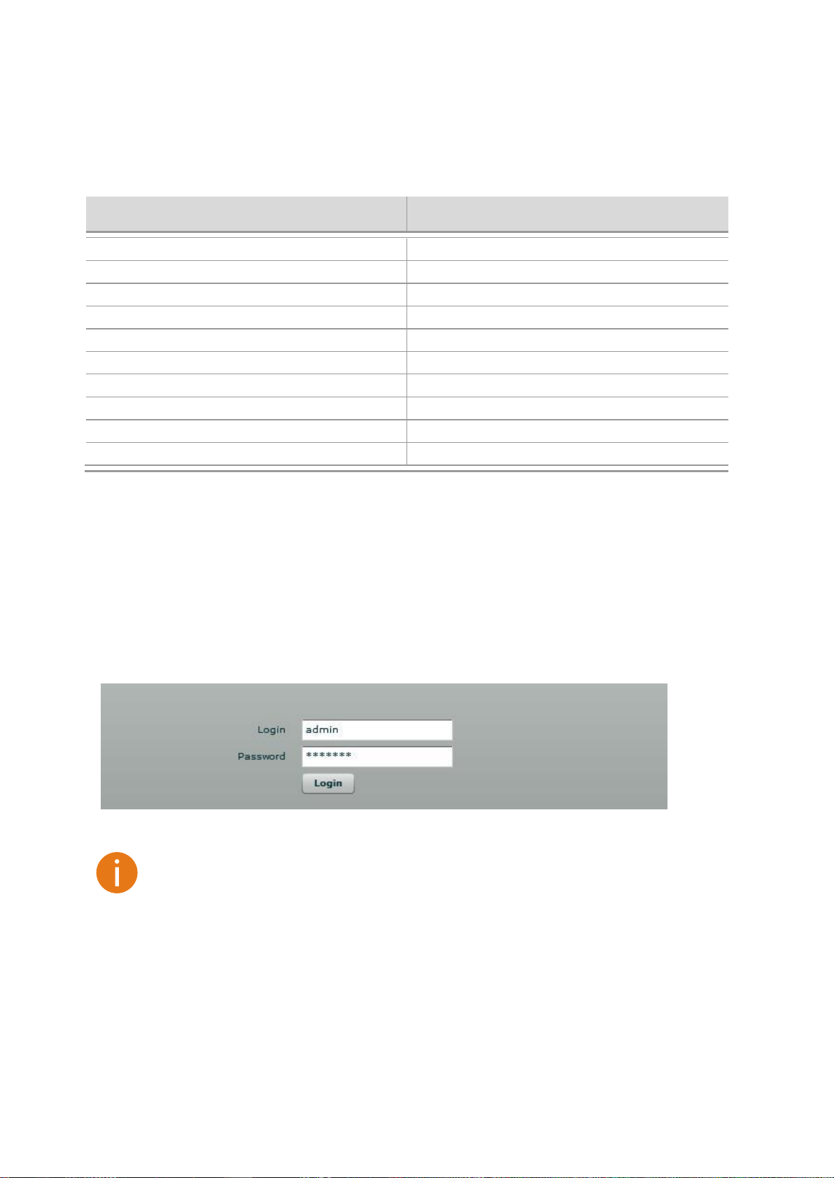
Step 1. Login in to the PTP unit web management. To access the PTP unit Web management
interface, configure your PC with a static IP address on the 192.168.2.0 subnet with mask
255.255.255.0. Connect the PTP unit in to the same physical network as your PC. Open
the Web browser and type the default IP address of the PTP unit
https://192.168.2.66/ and the login page will be loaded. Enter default administrator
login settings:
Figure 5 – Login Page
After successful administrator login you will see the main page of the PTP unit Web
management interface. The PTP unit now is ready for configuration.
Step 2. Specify the operation mode: Master or Slave.The difference in configuration of Master
and Slave is that the frequency does not need to be specified for the Slave. The Slave
scans the air and chooses the frequency automatically after finding the Master.
LigoWave Page 12
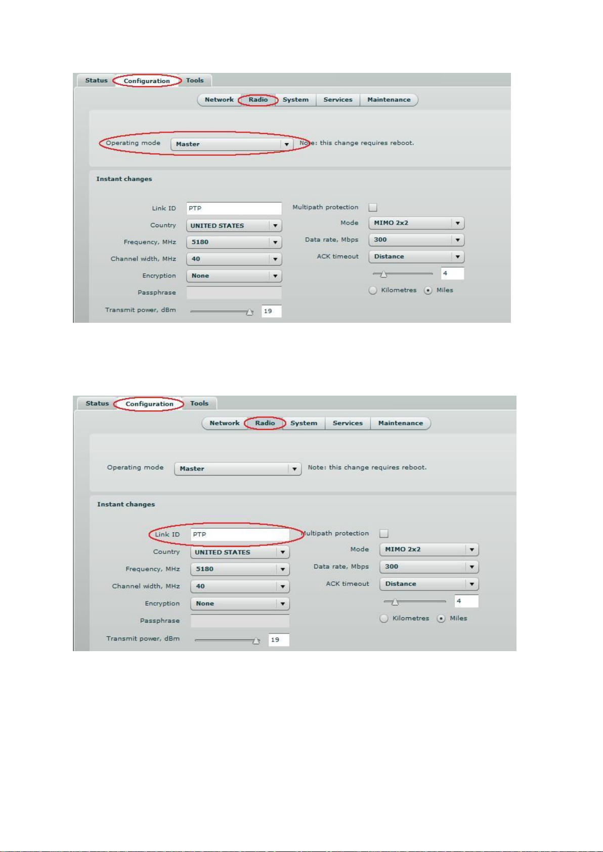
Figure 6 – Specify Unit's Operating Mode
Step 3. Specify a Link ID.LinkIDmust be identical for each unit of the same link.For instructions
on changing this setting refer to the Radiosection in the Web management chapter.
Figure 7 – Specify PTP Link ID
LigoWave Page 13

Step 4. Set Frequency at which PTP link will operate on Master unit. Change Frequency
applies only for Master units.The Slave unit will choose the frequency automatically after
the Master unit will be found. For instructions on changing this setting refer to the
Radiosection in the Web management chapter.
Figure 8 – Specify Frequency
Step 5. Set Channel width at which PTP link will operate. For instructions on changing this
setting refer to thesection in the Web management chapter.
Figure 98 – Specify Channel Width
LigoWave Page 14
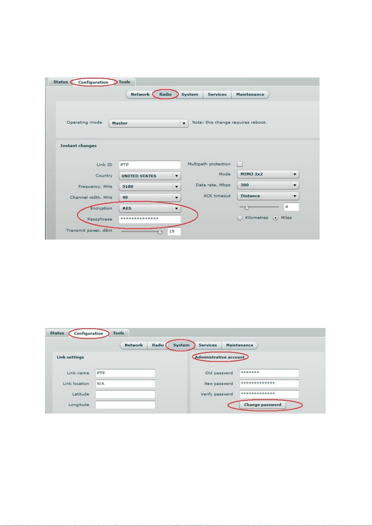
Step 6. Set link encryption for secure data transfer between PTP units.The security settings
(encryption and passphrase) must be the same on each side of the link otherwise the link
will not establish. For instructions on changing this setting refer to theRadiosection in the
Web management chapter.
Figure 9 – Set the Encryption
Step 7. Reduce Transmit Power before testing the units placed on a table. PTP units placed in
short distance with high transmit power may not work or even damage the peer's radio’s
receiver.
Step 8. Change web management login password. This is strongly recommended for security
reasons.For instructions on changing the administrator’s password refer to the
corresponding sectionAdministrative Account.
Figure 10 – Change Administrator's Password
Step 9. Save configuration and Reboot the device.
LigoWave Page 15
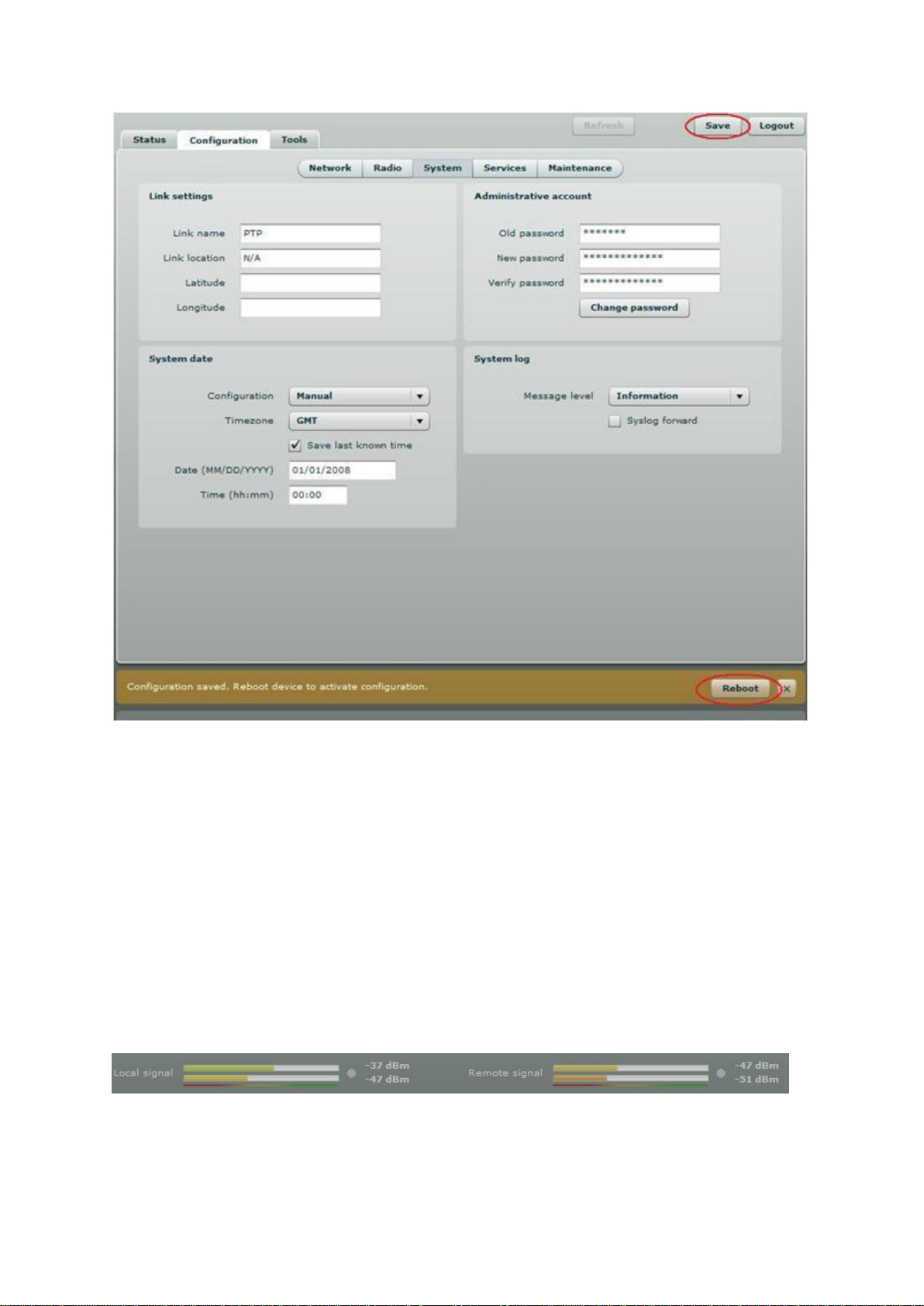
Figure 11 – Save Configuration
Step 10. Setup the second unit of the PTP link in the same way and check if configured units
established a Link.
Verify PTP Link Connection
After the both units of the PTP Link are configured, verify the PTP link quality:
Step 1. Connect to the unit’s web management interface.
Step 2. Check the Signal Indicator bar located at the bottom of the web management interface:
Figure 12 – Signal Indicator Bar
LigoWave Page 16

Step 3. Run the iperf tool (or use the Link Test) on server and client sides to verify the point-to-
point connection:
LigoWave Page 17

Figure 13 – iperf Results (TCP)
LigoWave Page 18

Figure 14 – iperf Results (UDP)
Step 4. If test results are meeting the requirement and are no configuration will be done
Transmit power should be increased, before mounting PTP units outside. Note that if
the distance between the units is short, do not set Transmit Power to the maximum
value. Observe the Signal Indicator bar – if it is red, decrease the Transmit Power.
LigoWave Page 19

Avoid standing directly in front of an operating antenna while aligning.
For detailed instructions on Antenna Alignment tool, refer to the respective sections:
Web management – Antenna Alignment
OLED screen –OLED control
Align Antenna
The PTP units are equipped with two signal strength feedback systems: antenna alignment tool on
the Web management interface and antenna alignment tool on the OLED screen.
Follow the steps to establish a radio link between the two PTP units and align the units for the best
signal strength.
Step 1. Ensure that power is supplied to both PTP link units.
Step 2. Ensure normal operation of the unit: check the OLED screen or Status page on the
Web management interface.
Step 3. Run the Antenna Alignment tool on the selected interface (OLEDor Web management)
and move the antenna in the horizontal and vertical planes until the maximum RSSI
visible on the Antenna Alignment graph is achieved.
Figure 15 – Antenna Alignment Tool on Web Management Interface
Figure 16 – Antenna Alignment Tool on OLED
Step 5. After the maximal RSSI is reached, tighten down the unit in the optimum position.
LigoWave Page 20

Web Management
PTP products are designed to provide superior performance at long range distances. With a
proprietary wireless driver that was written for the sole purpose of optimizing wireless point to point
links, one can achieve much higher throughput, especially at longer links, than standards based
products.
General Operation
This section provides information about concepts used in PTP unit’s Web management interface.
Instant Changes
Some of the PTP radio parameters do not require to reboot the device. These parameters are named
as instant changes.
Instant changes are useful for best performance parameters tuning. These parameters will take effect
as soon as the Apply button is clicked. When best configuration is founded press Save button and
reboot the device to make changes permanent. Otherwise all instant parameter changes will be lost
during PTP unit reboot.
Instant changes are on theRadiosection.
System Warnings and Errors
There are 3 types of system messages that must be noted: notifications, warnings and error
messages. These messages appear at the bottom of the page and can be closed by clicking the sign
.
For example notification messages are displayed in brown color and contain information about
configuration changes:
Figure 17 – Notification Message (1)
This message has an implemented Reboot button. Simply click this button and the PTP unit will be
rebooted at once – there is no need to navigate into theMaintenance page for additional action to
reboot the unit.
Notification messages also are on Wireless page Instant changes. This message informs you about
instant changes that were made:
Figure 18 – Notification Message (2)
LigoWave Page 21

Warning messages are displayed in red and contain PTP unit’s system cautions:
Figure 19 – Warning Message
The PTP unit contains built in validation for configuration settings in the web management interface. If
a user sets an incorrect value in the entry field, its frame turns red, and if the user tries to save such
incorrect configuration, an error message appears at the end of the page:
Figure 20 – Error Message
Signal Indicator
The PTP web management interface has a PTP link signal indicator. This indicator displays real-time
signal level in dBm of the Local and Remote units.
Figure 21 – PTP Signal Indicator
LigoWave Page 22

The color of the Signal indicator will change according to the signal level quality of the unit. The green
color means excellent link quality while the red color of the indicator means that link quality is poor.
The red circle beside full filled red indicator switches on immediately when the signal level becomes
too high and overload is detected.
Figure 22 – PTP Signal Indicator (too Strong Signal)
This may happen on an incorrect link layout, for example, in the case when the TX power parameter
in the PTP units is set to maximum but physically the units are too close to each other (e.g. testing
units are placed on a table).
The screenshot below displays Signal indicator if there is no PTP link established between PTP units:
Figure 23 – PTP Signal Indicator (no Link Established)
LigoWave Page 23

Status
Use the Status menu to check the current status of the PTP unit and established link (this is the
default page when accessing the device’s web management interface). The Information page displays
generic information and status of the PTP unit. The page is divided into three main categories:
System, Network and Wireless. The System section displays the identification information of the PTP
unit. The Wireless section presents main wireless settings. The Ethernet section describes the PTP
unit’s network identity and connectivity.
The information in the page can be updated using Refresh button.
Figure 24 – Status Page
System
System section displays general information of the PTP unit.
Product name – displays the product name.
Link name – displays the link name which is used to identify the PTP unit on the network.
LigoWave Page 24

Link location – displays the link location, which is used to identify the PTP unit on the network.
Latitude – displays the latitude coordinates of the device.
Longitude – displays the longitude coordinates of the device.
Firmware version – displays the device hardware and software version.
Uptime – displays the time, expressed in days, hours and minutes since the system was last
rebooted.
Average load – displays the average load of the device processor in the period of the last 1minute, 5
minutes and 15 minutes (a larger value means a larger average load on the processor).
<1.0 – System is idle
=1.0 – Normal load
>1.0 – Processor is busy.
Total memory, kB – displays total system memory.
Free memory, kB– displays free system memory.
System time – displays current system time.
Network
Ethernet link status – displays the status of the Ethernet link. A State UPindicates that the Ethernet
link is established. A state DOWNindicates that the Ethernet link is not established.
Ethernet speed/duplex – displays the negotiated speed and duplex of the Ethernet interface
specified in Mbps. The N/A will be displayed if the Ethernet status is down. Full duplex means that
data can be transmitted in both directions on a signal carrier at the same time. Half duplex means that
data can be transmitted in both directions on a signal carrier, but not at the same time. Auto means
that the system will detect link speed and duplex mode automatically.
MAC address – displays MAC address of the device.
Local IP – displays IP address of the local unit.
Remote IP – displays IP address of the remote unit. The N/A will be displayed if there is no PTP link
established.
Wireless
Wireless link status – displays the status of the Wireless link. A State UPindicates that the Wireless
link between local and remote units is established. A state DOWNindicates that the Wireless link
between local and remote units is not established.
Operating mode – displays the operating mode of the device. The operating mode can be Master or
Slave.
Link ID – displays PTP link ID, specified by the user.
Encryption – displays encryption method: none or AES.
Peer MAC – displays MAC address of the remote unit.
Frequency, MHz – displays frequency in MHz at which the PTP link communicates.
Channel width, MHz – displays the channel width (5/10/20/40) at which the PTP link communicates.
Data rate, Mbps – displays the data rate at which the PTP link communicates.
Transmit power, dBm – displays TX power value of the local PTP unit.
Remote transmit power, dBm – displays TX power value of the remote PTP unit.
LigoWave Page 25

Statistics
The statistics page displays detailed statistics of the PTP link performance. The Statistics page is
divided into the two sections: Networks statistics and W-Jet statistics.
Network statistics contains detailed statistics of Ethernet and Wireless interfaces:
Figure 25 – Statistics Page
RX bytes - displays the total number of received bytes by the Ethernet or Wireless interface of the
PTP link.
RX packets - displays the total number of received packets by the Ethernet or Wireless interface of
the PTP link.
RX errors - displays the total number of received corrupted packets by the Ethernet or Wireless
interface of the PTP link.
RX drops - displays the total number of dropped packets by the Ethernet or Wireless interface of the
PTP link.
TX bytes - displays the total number of sent bytes by the Ethernet or Wireless interface of the PTP
link.
TX packets - displays the total number of sent packets by the Ethernet or Wireless interface of the
PTP link.
TX errors - displays the total number of sent corrupted packets by the Ethernet or Wireless interface
of the PTP link.
TX drops - displays the total number of dropped packets by the Ethernet or Wireless interface of the
PTP link.
W-Jetstatistics displays detailed statistics of PTP link communication protocol.
Figure 26 – W-Jet Statistics
Local – statistics of the Local unit.
Remote – statistics of the Remote unit.
LigoWave Page 26

Point the mouse cursor on the diagram line and you will get the numeric expression of the
particular statistic.
Rx bytes – number of transmitted bytes. The number in brackets (+xx) displays the data change
since the last page refresh.
Tx bytes – number of the received bytes. The number in brackets (+xx) displays the data change
since the last page refresh.
Rx packets – number of received data packets The number in brackets (+xx) displays the data
change since the last page refresh.
Tx packets – number of transmitted data packets. The number in brackets (+xx) displays the data
change since the last page refresh.
Tx packets fail – number of failed to transmit packets. The number in brackets (+xx) displays the
data change since the last page refresh.
Tx packets retry – total number of attempts to retransmit data packets. The number in brackets (+xx)
displays the data change since the last page refresh.
RX duplicated packets – the number of received duplicated packets. The number in brackets (+xx)
displays the data change since the last page refresh.
CRC errors – the total number of CRC errors. The number in brackets (+xx) displays the data change
since the last page refresh.
Graphs
The Graphs page contains device statistics in graphic diagrams and is used for device monitoring.
Select the required statistics (RSSI, Traffic, RX/TX errors, Memory, CPU load or Frequency change)
and the corresponding graphic diagrams will be displayed. The statistics in diagrams are displayed on
hourly, daily, weekly, monthly or yearly basis; hourly is chosen by default. The option Display current
time set on the system gives possibility to convert the time stamps on the diagrams in current date,
set on the administrator’s PC.
To update statistics data click Refresh button.
RSSI diagram displays RSSI change of the Local and Remote PTP units at the chosen period:
LigoWave Page 27

Figure 27 – RSSI Graph
Traffic diagram displays Incoming and Outcoming traffic statistical data:
Figure 28 – Traffic Statistics Graph
RX/TX errors diagram displays statistical data of RX drop of the Local and Remote units, TX try of the
Local and Remote units:
LigoWave Page 28

Figure 29 – RX/TX Errors Statistics Graph
Memory diagram displays memory usage data:
Figure 30– Memory Status Graph
CPU load diagram displays device CPU load in appropriate time basis:
Figure 31 – CPU Load Graph
LigoWave Page 29

Frequency diagram displays device operating frequency in GHz:
Figure 32 – Frequency Graph at which PTP Link is Operating
LigoWave Page 30

Configuration
The Configuration page is subdivided into following pages:
Network – to set main network configuration for PTP device.
Radio – to setup radio settings of the PTP link.
System– to setup system date, administrator's access settings, configure system log feature.
Services – to setup SNMP, RCMS settings and configure device alerts.
Maintenance – for device firmware update, reboot, reset device to factory defaults,
troubleshooting file download and to view system log messages.
Network
The network configuration as described below is required for PTP management purposes. Use the
Network menu to setup the network settings of the PTP unit:
Figure 33 – Network Settings
Method – specify IP configuration mode:
Static IP – choose to specify static IP of the device.
Dynamic IP – choose to use dynamic IP given by the DHCP server (running DHCP server is
required).
IP address – specify the device IP address [digit and dots]. When shipped from the factory or reset to
factory settings, device defaults to a static IP address of 192.168.2.66.
Subnet mask – specify the device subnet mask [digit and dots]. When shipped from the factory or
reset to factory settings, the device defaults to a subnet mask of 255.255.255.0.
Default gateway – specify the IP address of the device gateway [digit and dots]. When shipped from
the factory or reset to factory settings, the device defaults to a gateway IP address of 192.168.2.1.
DNS server 1 – specify the IP address of the primary DNS server [digit and dots]. The DNS (Domain
Name Service) service translates Internet host names into their IP addresses.
DNS server 2 – specify the IP address of the secondary DNS server.
Ethernet configuration - configures the Ethernet link speed and the duplex mode of the Ethernet
port. Choose "auto" for automatic detection of link speed and duplex mode.
Management VLAN ID – specify the management VLAN ID [2-4094].If a management VLAN is
enabled, all traffic received by the device must by tagged with the management VLAN ID to access
the network. All non-tagged traffic will be dropped, thus reducing the risk of unauthorized access.
Restrict management to – select interfaces on which management access will be restricted.
LigoWave Page 31

Both sides (Master and Slave units) of the link must have the same Link ID name.
Radio
Use the Configuration | Radio menu to set up radio settings for the PTP link:
Figure 34 – Radio Settings
Operating mode – specify the operating mode of the local device to create PTP link [Master/Slave].
The device mode depends on the network topology.
Master – in this mode local device is the controlling PTP link unit.
Slave – in this mode local device connects to the Master unit.
Instant Changes
Applying parameters in the Instant changes section does not require device reboot, therefore making
easy parameters adjustment for best performance.
Link ID – specify known network name of the remote device to establish a PTP link.
Frequency – specify frequency at which the PTP link will be operating. If the device is operating in
Slave mode, it will not have the possibility to choose a frequency. The Slave scans the air and
connects to the Master automatically.
Channel width – choose the channel width in MHz [20/40].
LigoWave Page 32

Both sides (Master and Slave) of a link must have the same Link ID, Channel width and
Encryption specified.
Encryption – select the security level for the PTP link:
None – means no security on link.
AES – means encryption with passphrase.
Passphrase – specify passphrase of the AES security [8-63 characters]. This parameter appears and
is mandatory when AES security is chosen.
Transmit power – set the radio transmit power at which the device will transmit data. The larger the
distance, the higher transmit power is required. To set transmit power level use the slider or enter the
value manually. The transmit power level that is actually used is limited to the maximum value allowed
by FCC regulatory agency.
Multipath protection –if checked the signal will became more robust to signal interference caused by
signal echos or reflections. However as the drawback the enabled multipath protection will lead to
reduced link capacity.
Mode – choose the PTP antenna operating mode:
SISO – single input single output. The device will use only one antenna for data transfer. The
antenna will be chosen automatically.
MIMO – multiple input multiple output. The device will use two antennas for data transfer (two
simultaneous streams). In this mode the *link capacity doubles *if compared to SISO mode.
Data rate – select the device data transmission rates in Mbps from the drop-down list.
ACK Timeout – specify the Acknowledgement timeout either in distance, or in time expression:
Distance – specify the distance between PTP units, and ACK timeout will be calculated
automatically according the indicated distance in kilometers or myles.
Time – specify the ACK timeout in time expression.
LigoWave Page 33

System
The System page is subdivided into 4 sections:
Link settings – to specify PTP link settings.
System date – to setup system date and time of the PTP unit.
Administrative account – to change administrator's password.
System log – to configure logging of the system messages.
Link Settings
Figure 35 – Link Settings
Link name – specify name of the PTP link that is used to identify the unit on the network [maximum
255 ASCII characters].
Link location – describe the location of the PTP unit [maximum 255 ASCII characters].
Longitude – specify the longitude coordinates of the PTP unit [specific decimal format, e.q.
54.869446].
Latitude – specify the latitude coordinates of the PTP unit [specific decimal format, e.q. 23.891058].
Both coordinates helps indicate accurate location of the PTP unit's.
System Date
Use this section to manage the system time and date on the device automatically, using the Network
Time Protocol (NTP), or manually, by setting the time and date on the PTP unit.
The NTP (Network Time Protocol) client synchronizes the clock of the device with the defined time
server. Choose NTP from the configuration menu, select your location timezone and enter NTP server
in order to use the NTP service:
LigoWave Page 34

If the device hardware has no internal clock, the configured manual time will be reset to the
specified date and time after each device reboot.
Figure 36 – System Date: NTP Configuration
Configuration – choose the system clock configuration mode [NTP/Manual].
Timezone – select the timezone. Time zone should be specified as a difference between local time
and GMT time.
Save last known time – select to recall the timestamp that was saved on last reboot. When NTP is
enabled, this option will set system clock to last reboot time if no NTP servers are available.
NTP server – specify the trusted NTP server IP or hostname for synchronizing time with [IP address].
To adjust the clock settings manually, choose the configuration mode as Manual and specify the
following settings:
Figure 37 – System date: Manual Clock Configuration
Configuration – choose the system clock configuration mode [NTP/Manual].
Timezone – select the timezone. Time zone should be specified as a difference between local time
and GMT time.
Save last known time – select to recall the timestamp that was saved on last reboot.
Date – specify the new date value in format MM/DD/YYYY.
Time – specify the time in format hh:mm.
LigoWave Page 35

We recommend changing the default administrator password as soon as possible.
The only way to gain access to the web management if you forget the administrator
password is to reset the device to factory default settings.
Default administrator login settings are:
User Name: admin
Password: admin01
Administrative Account
The Administrative Account menu is for changing the administrator’s password.
Figure 38 – Changing the Administrator's Password
Old password – enter the old administrator password.
New password – enter the new administrator password for user authentication.
Verify password – re-enter the new password to verify its accuracy.
System Log
Use the Configuration | System menu to configure device to save log messages to the local or remote
server using standard syslog facility:
Figure 39 – System Log Configuration
LigoWave Page 36

To view logged system messages locally, navigate to the menuMaintenance
To communicate with SNMP manager you must configure SNMP communities and
identifiers on both ends (manager and agent).
Message level – specify system's message tracing level. The level determines the importance of the
message and the volume of messages generated by the PTP unitThe levels are in increased
importance order [emergency, alert, critical, error, warning, notice, information, debug]. Default: info.
The PTP unit can be configured to send system log messages to a remote server:
Syslog forward – select to enable remote system logging.
Forward server – specify the remote host IP address or hostname where syslog messages will be
sent.
Forward port – specify the port to which syslog messages will be forwarded [0-65535]. Default: 514.
Forward message level – specify the message level that will be send to the remote syslog server.
The level determines the importance of the message and the volume of messages generated by the
PTP unit. The levels are in order of increasing importance
[emergency/alert/critical/error/warning/notice/information/debug]. Default: information.
Forward backup – select to enable remote syslog logging backup.
Backup server – specify the backup host IP address or hostname where syslog messages will be
send to.
Backup port – specify the port to which syslog messages will be forwarded [0-65535]. Default: 514.
Services
The Services page is divided into 3 sections:
SNMP configuration – To enable SNMP and setup SNMP on the PTP unit.
RCMS configuration – to enable and setup RCMS agent on the PTP unit.
Alerts – to enable and setup system alerts.
SNMP Configuration
SNMP is the standard protocol that is widely used for remote network management over the Internet.
With the SNMP service enabled, the PTP unit can act as SNMP agent.
Figure 40 – SNMP Settings Configuration
Enable SNMP – specify the SNMP service status.
LigoWave Page 37

Name – displays an administratively assigned name.
System location – displays the physical location of the PTP unit [string].
R/O community – specify the read-only community name for SNMP version 1 and version 2c [string].
The read-only community allows a manager to read values, but denies any attempt to change values.
R/O user – specify the user name for read-only SNMPv3 access [string]. The read-only community
allows a manager to read values, but denies any attempt to change values.
R/O user password– specify the password for read-only SNMPv3 access [string].
WNMS Configuration
Wireless Network Management System (WNMS) is a centralized monitoring and management system
for wireless network equipment. The communication between managed devices and the WNMS
server is always initiated by anWNMSagent service running on every device.
Figure 41 – WNMS Agent Configuration
Enable WNMS – select to enable WNMS agent settings.
Server/Collector URL – specify the URL of the WNMS server that heartbeat notifications will be sent
to.
System Alerts
The PTP unit is able to send external alerts when there are system errors. The alerts can be sent via
SNMP Traps or/and SMTP notifications.
LigoWave Page 38

Figure 42 – System Alerts Configuration
Enable alerts – select to enable alert notifications on the system.
System check interval, s – specify interval in seconds at which the device will send notifications of
unexpected system behavior.
System alerts:
Wireless link status change – system will send notification on Wireless link status change.
Ethernet link status change – system will send notification on Ethernet link status change.
RSSI level lower than – system will send notification when RSSI reach value lower than
specified. Default: 25.
Noise level greater than – system will send notification when signal noise will reach value
greater than specified. Default: -60 dBm.
RX drop greater than – system will send notification when the specified percent of RX dropped
packets becomes higher than specified value.
TX retry greater than – system will send notification when the specified percent of TX retries
becomes higher than specified value.
Device reboot – system will send notification about unexpected or administrator initiated device
reboot.
SNMP TrapsSettings
Manager address – specify the IP address or hostname of Trap receiver.
Manager port – specify the port number of the Trap receiver. Default port number is 162.
Trap community – specify the SNMP community string. This community string acts as password
between SNMP manager and PTP unit. by default Trap community string is "public".
Use inform – select to wait for an acknowledgment from SNMP manager that trap was received.
LigoWave Page 39

Resetting the device is an irreversible process. Current configuration and the administrator
password will be set back to the factory default.
Retry count – specifies maximum number of times to resend an inform request [1-10]. Default: 5.
Retry timeout – specifies number in seconds to wait for an acknowledgment before resending
request [1-10]. Default: 1.
SMTPSettings
Server address – specify the IP address or hostname of the networked SMTP server.
Server port – specify the SMTP Port Number is the port number used by the networked SMTP server.
By default the port number is 25.
Source e-mail – specify the e-mail address that will be used by the PTP unit.
Destination e-mail – specify the e-mail address where the PTP unit will send the alert messages.
E-mail notification interval – specify interval in seconds at which the e-mail notification will be sent
from the PTP unit [0-86400]. If 0 specified, then device will send an e-mail notification immediately
after unexpected system behavior.
Maintenance
Use Maintenance menu for device firmware update, reboot, reset device to factory defaults,
troubleshooting file download, view system log messages and control OLED.
System Functions
Figure 43 – Main System Functions
Reboot device – reboot device with the last saved configuration.
Reset device to factory defaults – click to restore unit's factory configuration values.
Download troubleshooting file – click to download the troubleshooting file. The troubleshooting file
contains valuable information about device configuration, routes, log files, command outputs, etc.
When using the troubleshooting file, the device quickly gathers troubleshooting information
automatically, rather than requiring you to gather each piece of information manually.. This is helpful
for submitting problems to the support team.
Backup configuration file - click to save the current configuration file. The saved configuration file is
useful to restore a configuration in case of a device misconfiguration or to upload a standard
configuration to multiple devices without the need to manually configure each device through the web
interface..
Restore configuration from file - click to upload an existing configuration file to the device.
LigoWave Page 40

To change level of the system messages displayed in the Syslog viewer use menu System
Log.
View system log - click to view current trace messages. The Syslog viewer utility provides debug
information about the system services and protocols. If the device's malfunction occurs recorded
messages can help operators to locate misconfiguration and system errors. The syslog capability can
help operators to locate misconfiguration and system errors.
Figure 44 – System Log Viewer
Filter – filter content of the system messages by entering required words or symbols.
OLED Control
Use this section under Maintenance tab to control status or assign a PIN code for the PTP unit’s
OLED:
LigoWave Page 41

Do not switch off and do not disconnect the device from the power supply during the
firmware update process as the device could be damaged.
Figure 45 – OLED Control
Enable OLED – select to enable or disable OLED on the PTP unit.
PIN required – select to enable or disable OLED protection with PIN.
PIN – enter 4 digits for OLED protection.
Firmware Upgrade
To update your device firmware use the Firmware upgrade section under the Maintenance menu,
select the firmware file and click the Upload button:
Figure 46 – Firmware Upload on the System
Current version – displays version of the current firmware.
Uploadfirmware – click the button to select the new firmware image for uploading it to the device..
The device system firmware upgrade is compatible with all configuration settings. When the device is
upgraded with a newer version or the same version builds, all the system’s configuration will be
preserved after the upgrade.
The new firmware image is uploaded to the controller’s temporary memory. It is necessary to save the
firmware into the device permanent memory. Click the Upgrade button:
Figure 47 – Firmware Upgrade
Upgrade – upgrade device with the uploaded image and reboot the system.
LigoWave Page 42

Note that Site Survey function can take several minutes to perform.
Tools
Use the Tools menu to use the following device applications:
Site survey – to view the list of wireless networks in the surrounding area.
Antenna alignment – to align device antenna.
Link test – to check quality of the established PTP link.
Antenna Alignment
The antenna alignment test measures signal quality between the Master and Slave units. For best
results during the antenna alignment test, turn off all wireless networking devices within range of the
device except the device(s) with which you are trying to align the antenna. Watch the constantly
updated display in the antenna alignment test window as you adjust the antenna.
The Antenna Alignment test results appear when you click the Start button and finishes when you
click the Stop button.
Figure 48 – Antenna Alignment Tool
Average – if this option selected, the graph will display the average RSSI of both antennas.
Site Survey
The Site Survey test shows overview information for wireless networks in a local geographic area.
Using this test, an administrator can scan for working access points, check their operating frequency,
encryption, see signal/noise levels and view whether device has enabled W-Jet or not. This feature
may be used by the administrator find unused wireless channel so that PTP unit would not
interference with adjacent working devices thus getting best possible performance.
To perform the Site Survey test, click the Start scan button:
LigoWave Page 43

We recommend to ensure that there is no traffic on the link before running the Link Test as
results may not be completely accurate.
Figure 49 – Site Survey Tool
Start scan – click to perform the Site Survey test.
Show only W-Jet AP – select this option to sort Site Survey results.
Link Test
Use the Link test tool to check the quality of the established PTP link. This tool tests the throughput at
selected packet sizes and iterations. Link test can be run from either the Remote unit or Local unit.
Results represent the maximum, minimum and average value of the performed test.
LigoWave Page 44

Figure 50 – Link Test Tool
Iterations – specify number of test iterations.
Packet sizes – specify packet sizes in bytes at which the test will be performed.
Start – click to start the throughput test.
Stop – click to stop the throughput test.
LigoWave Page 45

Logout
ClicktheLogout link on the top right corner of the main menu to leave the Web management interface:
Figure 51 – Logout Page
Logout – click to leave the PTP unit Web management.
When the Logout button is clicked, the administrator is redirected to the login page of the PTP unit.
LigoWave Page 46

Appendix
A) Run PTP Link in Small Distance
Follow up the steps to run the PTP link for testing it in small distances (e.g. testing on a table) and
achieve throughput up to 70 Mbps.
Step 1. Power-up both units: Master and Slave.
Step 2. PTP units must be placed at least a distance of 2 meters from each other.
Step 3. Change major Radio parameters for both units (Master and Slave):
Figure 52 – Radio Settings
LigoWave Page 47
Channel width: 40 MHz
Transmit power:5dBm
Multipath protection:off
Mode:MIMO 2x2

Data rate: 300 Mbps
ACK timeout:Distance 0 km/miles
Click Apply button for configuration to take effect.
Step 4. Observe theSignal Indicatorbarat the bottom of the screen. If it is green the quality of
the link is excellent whereas the red color indicates a poor quality of the link. If results
do not meet the requirements increase or decrease the Transmit Power on Radio page
depending on the status of the Signal Indicator bar. TheSignal must be approximately
25-30dBm.
Step 5. Start the testing: start the iperfserver , then iperf client:
Figure 53 – iperf Results (TCP)
LigoWave Page 48

Figure 54 – iperf Results (UDP)
Step 6. If the result meets the requirements, before mounting PTP units outside, increase the
Transmit Power.
LigoWave Page 49

It is recommended to connect PC to the device via switch, as depending on PC OS
settings, the ARP table might be flushed during wired link status change (connecting the
device that will be reset).
Note that syntax of MAC address differs depending on OS:
Linux OS: AA:BB:CC:DD:EE:FF
Windows OS: AA-BB-CC-DD-EE-FF
B) Resetting Unit to Factory Defaults
PTP units have the capability of being reset to defaults by pinging the device with a certain packet
size when the radio is booting. During the startup of the device, when the drivers of the ethernet
interfaces are loaded, the discovery daemon is started. The daemon suspends startup process for 3
seconds and waits for ICMP "echo request" packet of length 369 bytes. If the packet received, the
discoveryd resets the device to default configuration.
Steps to reset to default settings:
Step 1. Power off the device.
Step 2. Obtain the device MAC address.
Step 3. Connect a PC to the same physical subnet as the device.
Step 4. Execute 'arp -s' command to assign the IP address (IP address should be from the
same subnet as PC) to the device MAC address:
arp -s <IP address to assign><device MAC address>
Step 5. Start pinging the device:
For Linux users: ping <IP address>-s 369
For Windows users: ping <IP address>-l 369 -t -w 0.2
Step 6. Power up device and wait about 30sec or more (depending on device hardware).
Step 7. Stop pinging the device, and let the device boot as usual. The device should start up
with factory default settings.
LigoWave Page 50

LigoWave Page 51
 Loading...