

Technical Manual
ISG LightWise™ Allegro
USB3 Vision™ Cameras
Version 1.3.1
Last Revision 3.31.15

ISG Allegro LightWise USB 3.0 Technical Manual Version 1.3.1
2
Table of Contents
FCC Compliance .................................................................................................................................................... 5
Hardware Warranty................................................................................................................................................. 5
WEEE ..................................................................................................................................................................... 5
Trademarks ............................................................................................................................................................. 5
About This Guide.................................................................................................................................................... 6
Contents .............................................................................................................................................................. 6
Assumptions........................................................................................................................................................ 6
Support................................................................................................................................................................ 6
LightWise Allegro USB 3.0 Specifications ............................................................................................................ 7
Specifications ...................................................................................................................................................... 7
Handling Precautions and Camera Care ............................................................................................................. 8
Case Temperature and Heat Dissipation ......................................................................................................... 9
Before You Install............................................................................................................................................. 10
Will your system configuration support the camera? ................................................................................... 10
Recommended USB3 Interface Cards: ......................................................................................................... 10
Do you have all the parts you need? ............................................................................................................. 10
Do you have the required software? ............................................................................................................. 10
Installing your Software.................................................................................................................................... 11
Overview....................................................................................................................................................... 11
SG LightWise Allegro USB3 GUI Software - 64-Bit Installation ............................................................... 12
GenICam™ - 64-Bit Software (8MB) Installation ....................................................................................... 15
Lightwise_Allegro_U3V_Driver Installation ............................................................................................... 18
Installing Your Camera..................................................................................................................................... 18
Using the ISG GUI................................................................................................................................................ 19
Custom Applications Built Using the ISG API ............................................................................................ 19
Using GenICam Applications ............................................................................................................................... 21
LightWise Allegro USB 3.0 Physical Description ............................................................................................... 22
LightWise Allegro USB 3.0 Dimensions.............................................................................................................. 23
Mounting with the Case or Optional Tripod Mount ............................................................................................. 24
Dust Protection...................................................................................................................................................... 24
Infrared Cutoff Filters ........................................................................................................................................... 25
Camera Interface and Connectors ......................................................................................................................... 26
USB 3.0 Connector ........................................................................................................................................... 26

ISG Allegro LightWise USB 3.0 Technical Manual Version 1.3.1
3
Interface Cables .................................................................................................................................................... 27
Interface Card........................................................................................................................................................ 27
Powering the Camera ............................................................................................................................................ 28
User Sets ............................................................................................................................................................... 28
GenICam User Set Control ............................................................................................................................... 29
Camera Firmware.................................................................................................................................................. 29
Determining Firmware Version ........................................................................................................................ 29
Upgrading Camera Firmware ........................................................................................................................... 29
Trigger/Strobe Control Input/Output Connector .................................................................................................. 30
Camera Trigger Details......................................................................................................................................... 30
Camera Strobe Details .......................................................................................................................................... 31
Programmable Strobe Output ............................................................................................................................... 32
Asynchronous Triggering ..................................................................................................................................... 33
GenICam Acquisition Control .......................................................................................................................... 34
Standard External Trigger................................................................................................................................. 35
Bulb Shutter Trigger ......................................................................................................................................... 36
Burst Mode Trigger (Edge Detect) ................................................................................................................... 37
Burst Mode Trigger (Level Detect) .................................................................................................................. 38
External Trigger Timing ....................................................................................................................................... 39
Asynchronous Software Triggering ...................................................................................................................... 39
Pixel Formats ........................................................................................................................................................ 40
Mono ................................................................................................................................................................. 40
RGB .................................................................................................................................................................. 40
YCrCb/YUV ..................................................................................................................................................... 40
Image Format Control....................................................................................................................................... 41
Shutter Types ........................................................................................................................................................ 42
Global Shutter ................................................................................................................................................... 42
Rolling Shutter .................................................................................................................................................. 43
Rolling Shutter with Global Reset .................................................................................................................... 44
Device Control ...................................................................................................................................................... 45
Image Format Control........................................................................................................................................... 47
Acquisition Control............................................................................................................................................... 48
Digital IO Control ................................................................................................................................................. 49
Analog Control...................................................................................................................................................... 50

ISG Allegro LightWise USB 3.0 Technical Manual Version 1.3.1
4
Transport Layer Control ....................................................................................................................................... 50
User Set Control.................................................................................................................................................... 51

ISG Allegro LightWise USB 3.0 Technical Manual Version 1.3.1
5
1. Background Information
FCC Compliance
This device complies with Part 15 of the FCC rules. Its operation is subject to the following two conditions:
1. This device may not cause harmful interference
2. This device must accept any interference received, including interference that may cause undesirable
operation.
Hardware Warranty
The LightWise Allegro USB 3.0 Digital Camera shall be covered under a hardware warranty for two (2) years. To
obtain detailed information on how to repair or replace your camera please see the terms and conditions on our
website. http://www.isgcameras.com/pdf/ISG_Standard_Tems_and_Conditions.pdf
WEEE
This product may not be treated as household waste. When the product is ready to be disposed of please ensure you
follow the appropriate waste handling method as the improper disposal of this product may cause potential hazards to
the environment and human health. For more detailed information about disposing of, or recycling of this product
please contact Imaging Solutions Group.
Trademarks
Imaging Solutions Group, LightWise
ISG Allegro LightWise USB 3.0 Technical Manual Version 1.3.1
6
2. Preface
About This Guide
This manual provides a detailed introduction and specification for the LightWise Allegro USB 3.0 Camera
system, including care, installation, use, interface guides, physical descriptions, and functional specification.
This camera system is one that is complex and dynamic, therefore if any errors or omissions are found during
use please contact us. See section on contact information.
This symbol highlights important information.
This symbol highlights important instructions, ones that you must follow to avoid
malfunction
Contents
This guide contains information and instructions and guidelines for the LightWise Allegro USB 3.0 Camera
system. Information can be found in the following sections
Assumptions
None
Support
Contact Type
Contact Information
Email
Sales@isgcameras.com; support@isgcameras.com
Knowledge Base
www.isgcameras.com
Downloads
http://www.isgcameras.com/support-allegro-usb3.php
Main Office
Imaging Solutions Group of NY, Inc
1387 Fairport Road, Suite 890
Fairport, NY 14450

ISG Allegro LightWise USB 3.0 Technical Manual Version 1.3.1
7
LightWise Allegro USB 3.0 Specifications
Building on the success of the original LightWise 1394 camera se ries, the LightWise Allegro camera offers a
many new features, including enhanced opto-isolated GPIO, an on-camera frame buffer, non-volatile flash
memory for data storage, new trigger modes and improved imaging performance.
Specifications
Model
Version
MP
Imaging Sensor
LW-AL-CMV-2000-USB3-C
Color
2 MP
CMOSIS CMV-2000, 2/3” CMOS
Global Shutter, 5.5u pixel
up to 340 fps using internal buffer
LW-AL-CMV-2000-USB3-M
Mono
2 MP
CMOSIS CMV-2000, 2/3” CMOS
Global Shutter, 5.5u pixel
up to 340 fps using internal buffer
LW-AL-CMV-4000-USB3-C
Color
4 MP
CMOSIS CMV-4000, 1” CMOS
Global Shutter, 5.5u pixel
up to 150 fps using internal buffer
LW-AL-CMV-4000-USB3-M
Mono
4 MP
CMOSIS CMV-4000, 1” CMOS
Global Shutter, 5.5u pixel
up to 150 fps using internal buffer
LW-AL-CMV-12000-USB3-C
Color
12 MP
CMOSIS CMV-12000, 4/3” CMOS
Global Shutter, 5.5u pixel
up to 80 fps using internal buffer
LW-AL-CMV-12000-USB3-M
Mono
12 MP
CMOSIS CMV-12000, 4/3” CMOS
Global Shutter, 5.5u pixel
up to 80 fps using internal buffer
LW-AL-IMX174-USB3-C
Color
2.3 MP
SONY IMX174, 1/1.2”
Global Shutter, 5.86u pixel
up to 120 fps
LW-AL-IMX174-USB3-M
Mono
2.3 MP
SONY IMX174, 1/1.2”
Global Shutter, 5.86u pixel
up to 120 fps
LW-AL-IMX249-USB3-C
Color
2.3 MP
SONY IMX249, 1/1.2”
Global Shutter, 5.86u pixel
up to 60 fps
LW-AL-IMX249-USB3-M
Mono
2.3 MP
SONY IMX249, 1/1.2”
Global Shutter, 5.86u pixel
up to 60 fps

ISG Allegro LightWise USB 3.0 Technical Manual Version 1.3.1
8
Imaging Performance
Sensor Image Data
A/D Converter
10 and or 12 bit in sensor
Video Data Output
8,10 and 12 bit firmware available
Image Data Formats
Mono:8 or 10 bit packed, 12 bit firmware available
Color: Bayer 8 or 10 bit packed, RGB, YCC 422
Image Processing Pipeline
(Color Models)
Bayer Interpolation, Gamma, White Balance, Color Space Conversion and Correction
Partial Image Modes
Binning and Region of Interest (ROI) Modes
Shutter
Global Shutter with Programmable Integration
Gain
Programmable Digital Gain
Digital Interface
USB 3.0 interface with screw locks for camera control, data and power
Transfer Rates
5 Gbit/s
GPIO
12-pin Hirose HR10A GPIO, opto isolated trigger, 2 opto isolated strobes
External Trigger Modes
Single Frame, Burst Mode, Bulb Mode
Synchronization
Via external trigger or software trigger
Image Buffer
256 MB Buffer
Flash Memory
8 MB nonvolatile flash memory
Dimensions
Mass
Power Consumption
5V via USB3.0 interface, maximum <4.5W
Machine Vision Standard
IIDC v 1.32, USB3 Vision v1
Camera Control
Via ISG SDK, CSRs, or third party software
Camera Updates
In-field firmware updates
Lens Mount
C-mount
Temperature
Operating: 0o to 45o C; Storage -30o to 60o C
Humidity
Operating: 20 to 80% (no condensation); Storage 20 to 90% (no condensation)
Compliance
CE, FCC, RoHS
Operating System
Windows 7, 8, 8.1
Warranty
Two Years
Handling Precautions and Camera Care
Opening the camera housing will cause damage and will void the hardware warranty detailed in the beginning
of this document. Since the LightWise Allegro Camera is a precisely manufactured device it must be handled
with care. Some tips for device care are below:
1. Electrostatic charging should be avoided
2. Avoid touching the lens when handling the camera, as fingerprints will affect the quality of the image
produced by the device.
3. When cleaning the lens do not use excessive force and please use a standard camera lens cleaning kit or
clean dry cotton cloth.
4. Avoid exposure to bright sunlight, dusty environments, rain etc. as this may cause problems with the
electronic and optics of the system.
5. Mishandling of the device such as excessive shaking, dropping and force should be avoided.

ISG Allegro LightWise USB 3.0 Technical Manual Version 1.3.1
9
Case Temperature and Heat Dissipation
For the camera to function correctly, it is required to provide sufficient heat dissipation for the internal
operating environment. Since the camera electronics are neatly packed into a small space it can become very
warm to the touch when running in some modes; this is expected behavior and will not damage the electronics.
The use of a cooling fan to set up positive air flow around the camera in order reduce is suggested. Please take
into consideration the following precautions:
1. Mount the camera on a heat sink that is composed of a heat conductive material like aluminum, such as
a camera mounting bracket.
2. Ensure the flow of heat from the camera case to the bracket is not blocked by a non -conductive material
like plastic.
3. Provide enough space around the camera to facilitate the free flow of air.

ISG Allegro LightWise USB 3.0 Technical Manual Version 1.3.1
10
3. LightWise Allegro USB 3.0 Installation
Before You Install
Will your system configuration support the camera?
Operating System
CPU
RAM
Video
Ports
Software
Windows 7, 8,
8.1
(Linux
Supported via
USB3 vision
Standard)
Intel Core
i3 3.1
GHz or
equivalent
4GB
128 MB
RAM
PCIe 2.0 compatible
host controller with
USB 3.0 connector
Microsoft Visual Studio
2010
(to compile and run
example code)
Recommended USB3 Interface Cards:
The USB3 desktop motherboards supporting the Intel Z77 or Z78 chipset or newer will support high bandwidth
USB3. USB3 cards may also be added to provide the ports. The two cards below have been successfully tested
with ISG cameras:
1. 2-port card, both ports share a total 5 Gbps bandwidth:
http://isgcameras.com/startech_2-port_usb3_hba_pexusb3s24.php
2. 4-port card, with each port having its own 5 Gbps bandwidth for total of 20 Gbps.
http://isgcameras.com/startech_4-port_usb3_hba_pexusb3s44v.php
Do you have all the parts you need?
To install your camera you will need the following components:
1. USB 3.0 cable (see Interface Cables)
2. 12-pin Trigger/Strobe cable
3. C-mount Lens
4. Tripod adapter (optional) (see Mounting with the Case or Optional Tripod Mount)
5. Interface card
ISG sells a number of the additional parts required for installation. To purchase, please visit the ISG Web Site.
www.isgcameras.com
Do you have the required software?
There are many helpful resources available to you on the ISG downloads page including:

ISG Allegro LightWise USB 3.0 Technical Manual Version 1.3.1
11
1. Software; including drivers that are needed for installation
2. Firmware; updates and release notes.
3. Dimensional drawings and CAD Models
4. Documentation
Installing your Software
Overview
In order to operate the ISG USB3 camera, the following software installation programs should be loaded from
the ISG website (http://www.isgcameras.com/support-allegro-usb3.php) The first is the ISG UI software,
labelled as “ISG LightWise Allegro USB3 GUI Software - 64-Bit”. This will install a folder containing the
ISG GUI application, as well as a driver installation subfolder “ Lightwise_Allegro_U3V_Driver”. In addition,
the GenAPI reference software library is required. This can be loaded from the link called “ GenICam™ - 64-
Bit Software (8MB)”. These two installations must both be performed, and the driver installer run, in order to
complete all of the required software for the camera and can be done prior to installing the camera.
After installing the ISG LightWise Allegro USB3 GUI Software, open a browser window to the install folder.
By default this will be “C:\ISG\Usb3GUI_Install\. There resides subfolder Lightwise_Allegro_U3V_Driver.
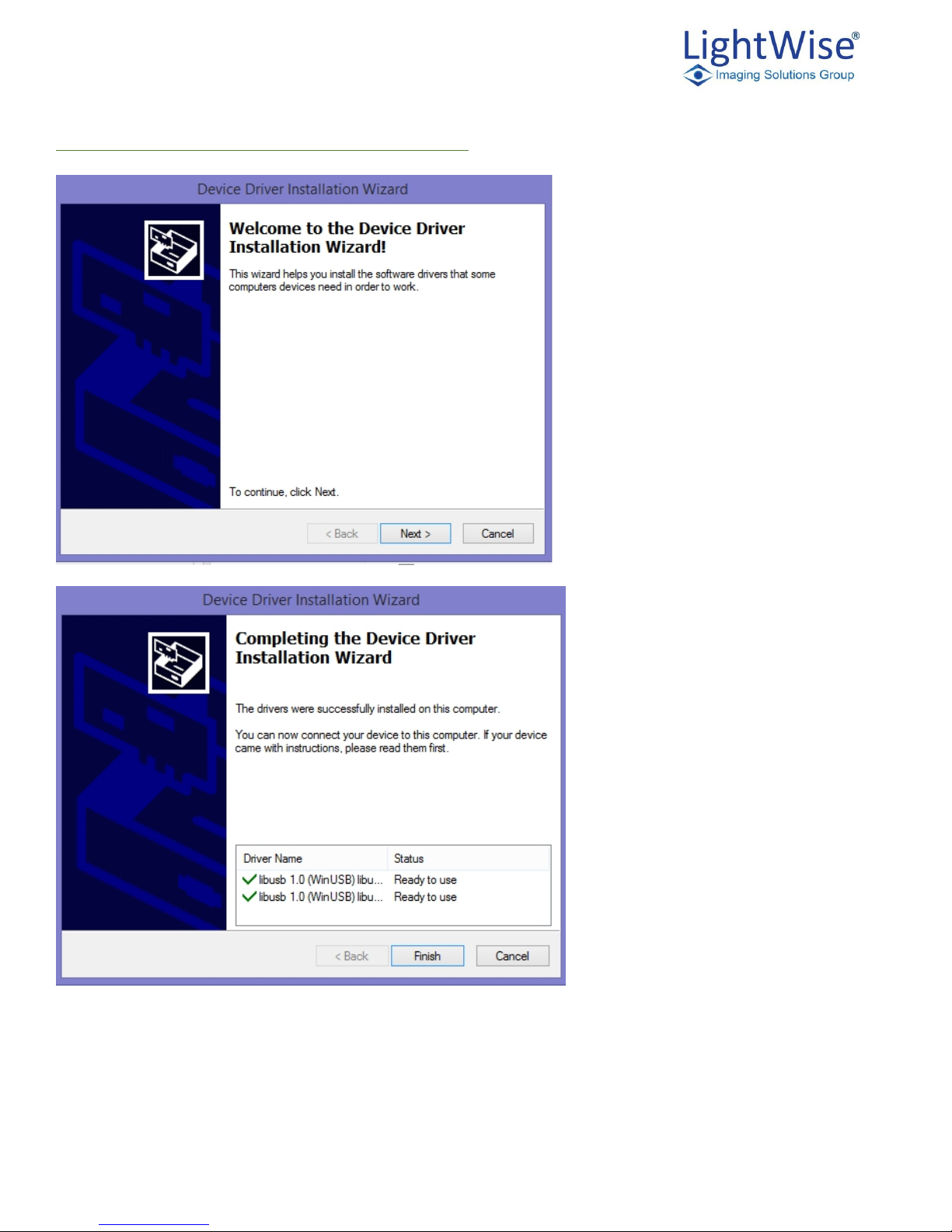
In that folder is the driver installation application LightwiseAllegro_DriverInstall.exe. Running this
application will start a device driver installation wizard. Agree to all of the pop up menus that arise based on
this driver update. The driver installation can take several minutes in some cases, but eventually the process
will complete with a dialog that reports success. When the ISG Allegro camera is connected, the device
manager should show the camera’s association to the WinUSB driver, although this can also take some time
when the camera is connected for the first time.
Once driver installation is successfully completed and the GenICam installation is done, the ISG GUI can be
used to connect to, and demonstrate functionality of the USB3 camera.
ISG Allegro LightWise USB 3.0 Technical Manual Version 1.3.1
12
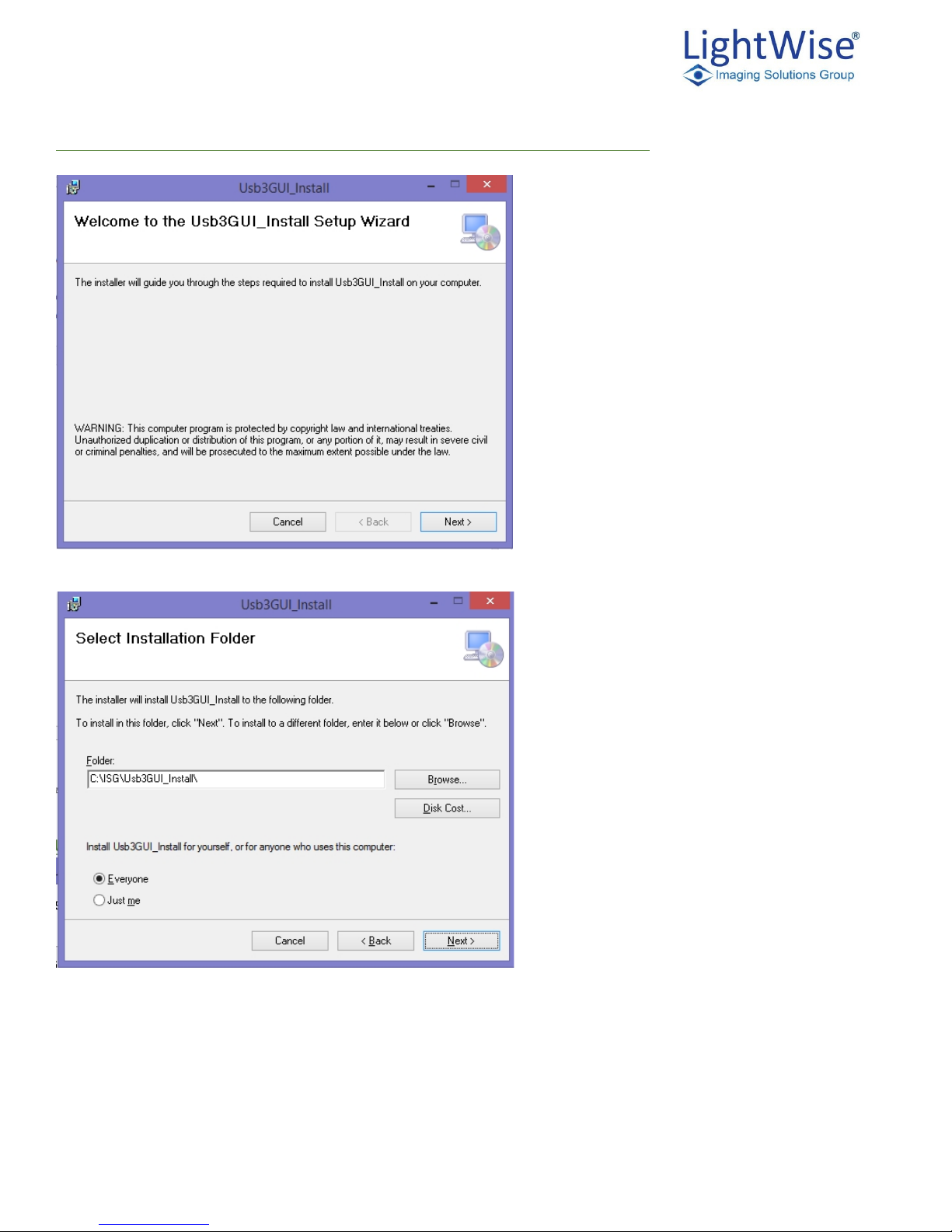
ISG LightWise Allegro USB3 GUI Software - 64-Bit Installation
Select Next
Select Next
ISG Allegro LightWise USB 3.0 Technical Manual Version 1.3.1
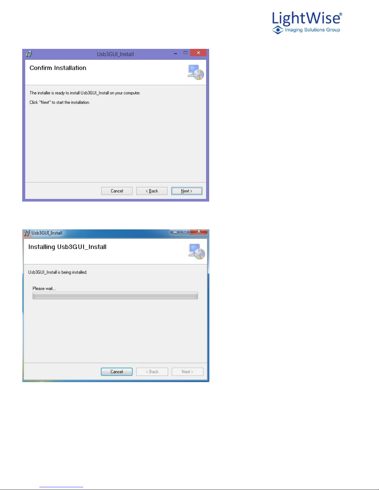
13
Select Next to launch installation
Please wait while the installtion completes
ISG Allegro LightWise USB 3.0 Technical Manual Version 1.3.1
14
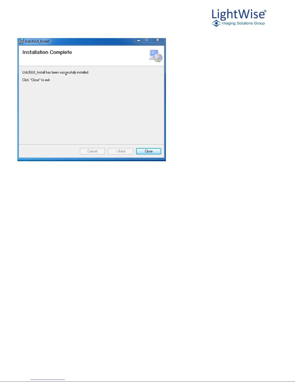
Select Close to complete the installation
ISG Allegro LightWise USB 3.0 Technical Manual Version 1.3.1
15
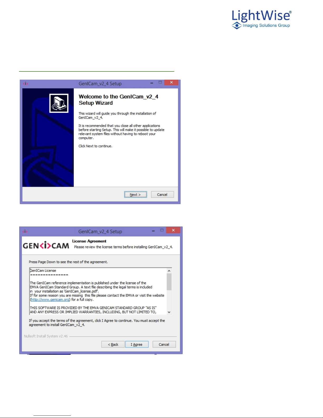
GenICam™ - 64-Bit Software (8MB) Installation
Select Next
Select I Agree
ISG Allegro LightWise USB 3.0 Technical Manual Version 1.3.1
16
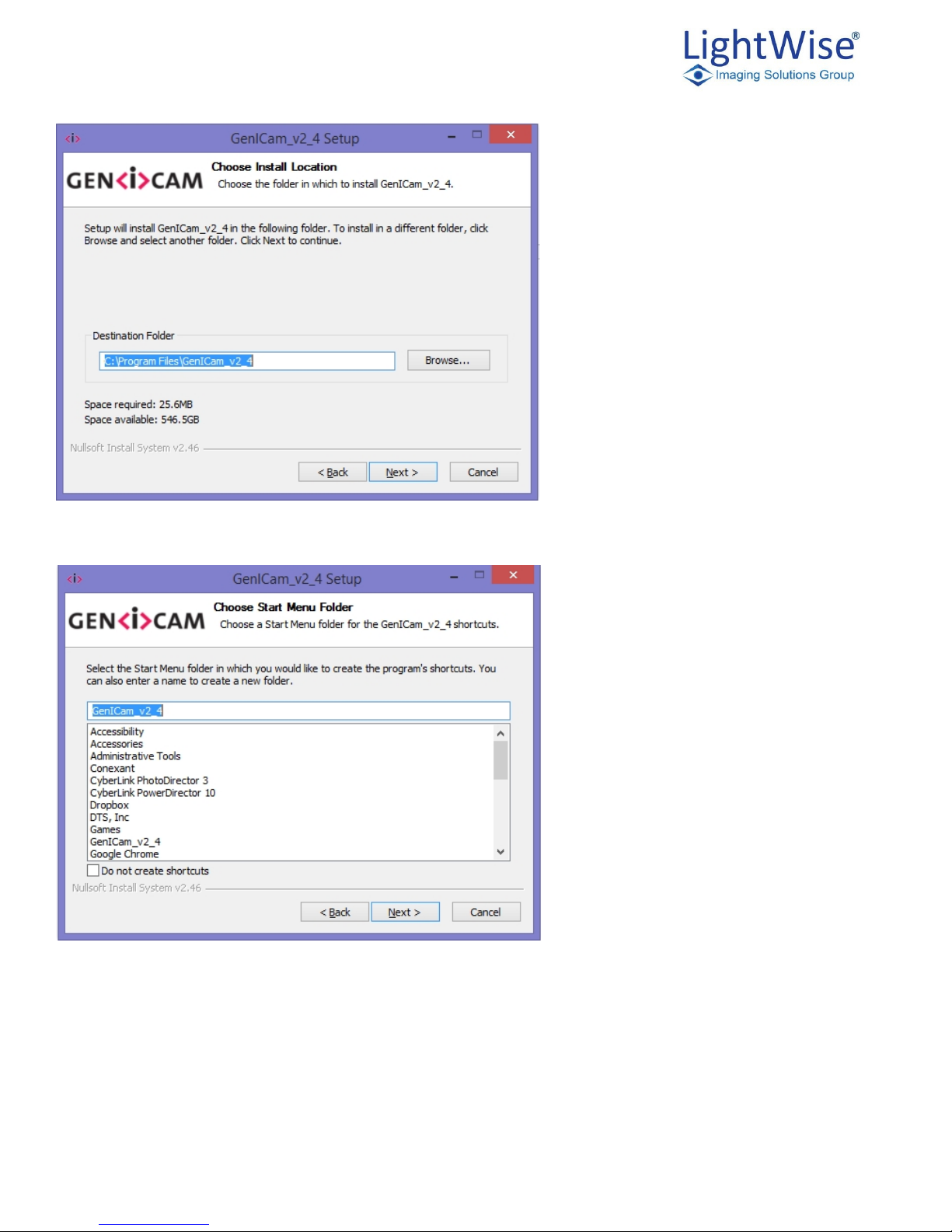
Select Next
Select Next
ISG Allegro LightWise USB 3.0 Technical Manual Version 1.3.1
17
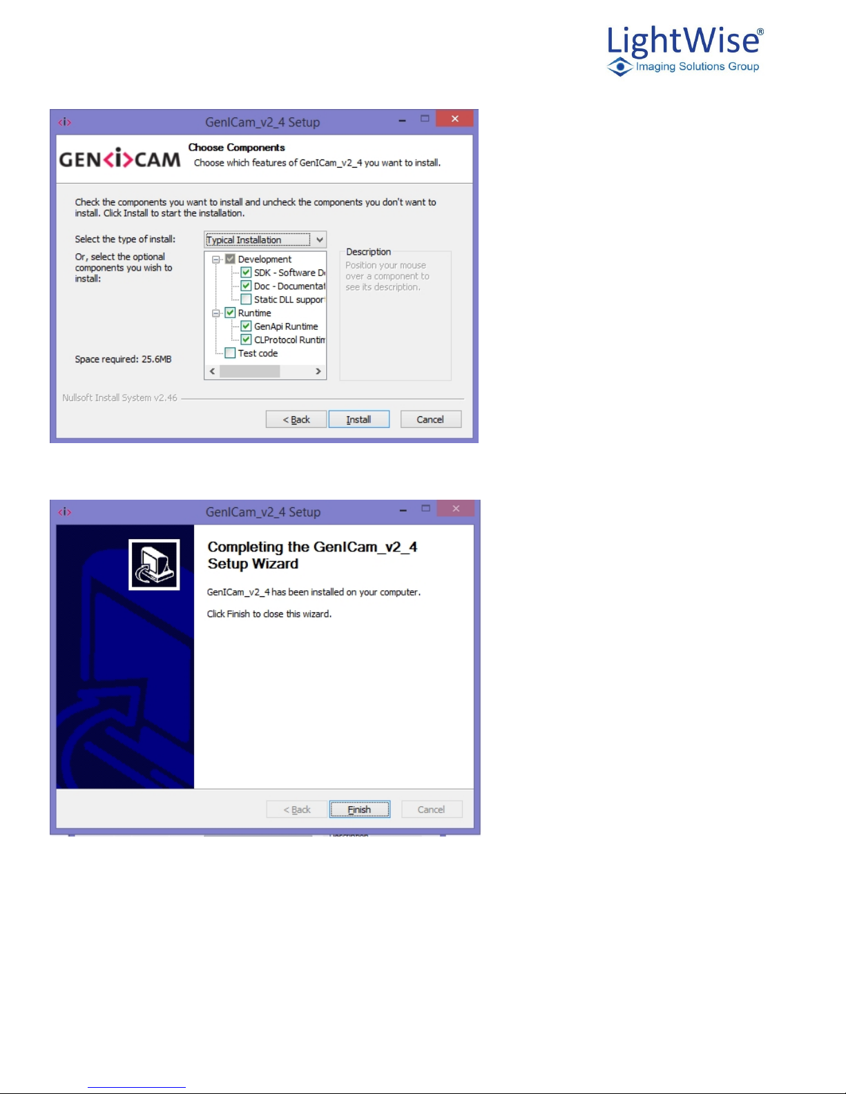
Select Install and the installation will take a little while to complete.
Select Finish and the GenICam installation is complete!
ISG Allegro LightWise USB 3.0 Technical Manual Version 1.3.1
18
Lightwise_Allegro_U3V_Driver Installation
Select next
Select finish
Installing Your Camera

ISG Allegro LightWise USB 3.0 Technical Manual Version 1.3.1
19
1. Install the Tripod Mounting Bracket (optional)
2. Attach a Lens
a. Unscrew the dust cap from the C-mount lens holder to install a lens
3. Connect the interface card and cable to the camera
a. Plug the interface cable into the host controller and the camera. The cable jack screws should be
used for a secure connection
4. Plug in the GPIO Connector (optional)
a. GPIO can be used for trigger and strobe
5. Confirm successful installation
a. Check the device manager to confirm the installation was successful
b. Go to the start menu and select run and enter devmgmt.msc
c. Verify the camera is listed as LightWise Allegro U3V (this will normally be found under the
“ibusb (WinUSB) devices” header)
4. Tools to Control the LightWise Allegro USB 3
The LightWise Allegro USB 3.0's features can be accessed using various controls, including:
1. ISG API examples and the ISG GUI program
2. GenICam Applications
3. Third-party Software Applications
Examples of the controls are provided throughout this document. Additional information can be found in the
appendices.
Using the ISG GUI
The user can monitor or control features of the camera through ISG API examples, or through the ISG GUI.
The ISG GUI is a streaming image viewer included with the ISG camera that can be used to test many of the
capabilities of your compatible ISG camera. It allows you to view a live video stream from the camera, save
individual images, adjust the various video formats, frame rates, properties and settings of the camera, and
access camera registers directly.
Custom Applications Built Using the ISG API
The ISG Application Programming Interface that allows customers to create custom applications to control ISG
Imaging Products. Included in downloads that are available on the ISG web site are a number of source code
examples to help programmers get started.
Available downloads include:
1. Compiled and installable GUI.

ISG Allegro LightWise USB 3.0 Technical Manual Version 1.3.1
20
2. Source code examples from the ISG GUI indicating how to access camera parameters.
(IsgU3VGuiSample.zip)
3. The ISG dll Header file which describes the API, and an API description document
(ISG_USB3_Interface_Guide_ISG_U3V_API.pdf).
4. Instructions on how to locate the Header file can be found in:
ISG_USB3_Interface_Guide_ISG_U3V_API.pdf

ISG Allegro LightWise USB 3.0 Technical Manual Version 1.3.1
21
Using GenICam Applications
USB3 Vision is a communication interface for vision applications base d on the USB 3.0 technology. All
cameras supporting USB3 Vision interact the same way with software also supporting USB3 Vision.
The standard defines required elements for camera identification, control, and output. It uses GenICam, a
programming interface for camera attribute control. GenICam allows camera vendors to define features and
attributes in an XML file stored inside the camera. The file is parsed by the host application when the camera is
initially discovered. One of the key benefits of GenICam is the ability for camera vendors to introduce new
camera-specific features without needing to update the host application.
Each camera attribute, such as exposure time, is controlled by a specific GenICam feature. The camera includes
an XML device description file for interfacing with third-party GenICam-compliant APIs. A full listing of
features that are included in the XML file is provided in GenICam Features. Throughout this document,
GenICam features are referenced with their applicable operation.
For more information on the USB3 Vision standard, visit visiononline.org.
For more information on GenICam, visit http://www.isgcameras.com/support -allegro-usb3.php

ISG Allegro LightWise USB 3.0 Technical Manual Version 1.3.1
22
5. LightWise Allegro USB 3.0 Physical Interface
LightWise Allegro USB 3.0 Physical Description
1. Lens holder
C Mount Lens ready. (CS Mount available by special order.
2. Glass/IR filter system
Dust protective glass on monochrome cameras, IR Cut filter on color models. Removable and
mounted behind Lens Holder
3. M3x.5 THD x 5 DP mounting holes
Eight locations on camera case for multiple mounting options.
4. General purpose I/O connector
The 12 – pin Trigger/Strobe connector. See Trigger and Strobe Control
5. Status LED
This light indicates the current state of the camera operation. See Status Indicator LED
6. USB3 connector
See USB 3.0 Connector

ISG Allegro LightWise USB 3.0 Technical Manual Version 1.3.1
23
LightWise Allegro USB 3.0 Dimensions
LW-AL-CMV-4000/2000 shown below
Drawings and 3D models for all model numbers available on the ISG Web Site
FRONT PANEL SIDES BOTTOM
REAR PANEL

ISG Allegro LightWise USB 3.0 Technical Manual Version 1.3.1
24
Mounting with the Case or Optional Tripod Mount
The case provides the following mounting holes:
1. Eight (8) M3 x .5 mounting holes on the top bottom and sides of the case.
2. The two M3 x .5 mounting holes on the front bottom of the case can be used to attach the optional tripod
mount.
The tripod mount is designed to accept standard tripods with a sta ndard 1/4" - 20 threading.
Tripod Mount:
Dust Protection
Designed to prevent dust from falling directly onto the sensor’s protective glass surface the LightWise Allegro
comes with protective camera housing. The shielding is accomplished by placing a piece of clear glass
(monochrome camera models) or an IR cut off filter (color models) which sits above the surface of the sensors
glass with a removable plastic retainer that keeps the glass/filter in place. The possibility of damage to the
sensor when cleaning or of interference from dusty is greatly reduced by the increased distance between the
imaging surface and the location of potential dust particles. Additional measures of protection:
1. Cameras are sealed when they are shipped. To avoid contamination, seals should not be broken until
cameras are ready for assembly at customer's site.
2. Use caution when removing the protective glass or filter. Damage to any component of the optical path
voids the Hardware Warranty.
3. Removing the protective glass or filter alters the optical path of the camera, and may result in problems
obtaining proper focus with your lens.

ISG Allegro LightWise USB 3.0 Technical Manual Version 1.3.1
25
Infrared Cutoff Filters
ISG color camera models are shipped with an infrared (IR) cut- off filter. This filter can reduce sensitivity in the
near infrared spectrum and help prevent smearing. The properties of this filter are illustrated in the transmission
curve below. In monochrome models, the IR filter is replaced with a transparent piece of glass.
0
10
20
30
40
50
60
70
80
90
100
0 200 400 600 800 1000 1200
SP645 IR Cut Filter Transmission Curve - (Color Models)

ISG Allegro LightWise USB 3.0 Technical Manual Version 1.3.1
26
Camera Interface and Connectors
USB 3.0 Connector
The camera is equipped with a USB 3.0 Micro-B connector that is used for data transmission, camera control
and power. For more detailed information, consult the USB 3.0 specification available from
http://www.usb.org/developers/docs/.
Figure 4.5: USB 3.0 Micro B Connector
Pin
Signal Name
Description
1
VBUS
Power
2
D-
USB 2.0 differential pair
3
D+
4
ID
OTG identification
5
GND
Ground for power return
6
MicB_SSTX-
SuperSpeed transmitter differential
pair
7
MicB_SSTX+
8
GND_DRAIN
Ground for SuperSpeed signal return
9
MicB_SSRX-
SuperSpeed receiver differential pair
10
MicB_SSRX+
TABLE 4.1: USB 3.0 MICRO-B CONNECTOR PIN ASSIGNMENTS
The USB 3.0 Micro-B receptacle accepts a USB 2.0 Micro-B plug and, therefore, the camera is backward
compatible with the USB 2.0 interface.
When the camera is connected to a USB 2.0 interface, it runs at USB 2.0 speed,
and maximum frame rates are adjusted accordingly based on current imaging
parameters.

ISG Allegro LightWise USB 3.0 Technical Manual Version 1.3.1
27
Interface Cables
Because there is not a standard maximum cable length specified in the USB 3.0 standard you may need to
purchase a recommended cable. To do so please visit the ISG web site. www.isgcameras.com.
Interface Card
In order to achieve optimum benefits of the USB 3.0 the camera must connect to a USB PCIe 2.0 card.
The camera must connect to an interface card which is often referred to as a host adapter, a bus controller or a
network interface card (NIC)

ISG Allegro LightWise USB 3.0 Technical Manual Version 1.3.1
28
6. General LightWise Allegro USB 3.0 Operation
Powering the Camera
The power consumption specification is: 5 V via USB 3.0 interface, maximum 900mA.
The USB 3.0 Micro-B connector provides a power connection between the camera and the host computer.
The ideal input voltage is nominal 5 V DC. Full power, 900mA USB3 host ports must be used.
Caution must be used with USB2 ports or hubs which do not provide the specified 900m mA. USB2 only
provides 500 mA per port. For applications using USB2 ports, external 6V power may need to be provided via
the trigger and strobe cable, or by using a special USB3 Y-Cable cable which allows summing of power from
multiple USB2 ports.
User Sets
The camera can save and restore settings and imaging parameters via on- board user configuration sets, also
known as memory channels. This is useful for saving default power-up settings, such as gain, shutter, video
format and frame rate, and others that are different from the factory defaults.
User Set 0 stores the factory default settings that can always be restored. Two additional user sets are provided
for custom default settings. The camera initializes itself at power-up, or when explicitly reinitialized, using the
contents of the last saved user set. Attempting to save user settings to the (read-only) factory default user set
causes the camera to switch back to using the factory defaults during initialization.
The following camera settings are saved in user sets.
1. Acquisition Frame Rate and Current Frame Rate
2. Image Data Format, Position, and Size
3. Current Video Mode and Current Video Format
4. Frame information
5. Trigger Mode and Trigger Delay
6. Imaging Parameters
7. GenICam User Set Control

ISG Allegro LightWise USB 3.0 Technical Manual Version 1.3.1
29
GenICam User Set Control
Camera Firmware
Firmware is programming that is inserted into the programmable memory (programmable ROM) of ISG
cameras. Firmware is created and tested like software. When ready, it can be distributed like other software and
installed in the programmable memory by the user.
The latest firmware versions often include significant bug fixes and feature enhancements. To determine the
changes made in a specific firmware version, consult the Release Notes.
Firmware is identified by a version number, a build date, and a description.
Determining Firmware Version
To determine the firmware version number of your camera:
1. In the ISG, open the "About" Dialog.
2. Query the GenICam feature DeviceFirmwareVersion.
Upgrading Camera Firmware
Camera firmware can be upgraded or downgraded with either an earlier or later version by using tools located
on the ISG website. www.isgcameras.com
Name
Display Name
Description
Value
UserSetSelector
User Set Selector
Select the feature user set to load, save, or configure
Default = 0
User Set 1 = 1
User Set 2 = 2
UserSetLoad
Load Selected
Loads the User Set specified by UserSetSelector and makes it
active
Write Only
UserSetSave
Save Selected
User Set
Saves the user set specified by the User Set Selector to the
non-volatile memory of the device
Write Only
UserSetDefault
Default User Set
Select the feature user set to load and make active by default
when the device is reset
Default
User Set 1
User Set 2

ISG Allegro LightWise USB 3.0 Technical Manual Version 1.3.1
30
7. Trigger/Strobe Control
Trigger/Strobe Control Input/Output Connector
Connector Information:
On Camera: Hirose R10A-10R-12SB(71) - J1
Mating Plug (For Cables): Hirose HR10A-10P-12P(73)
Pin
Assignment
J1.1
Reserved do not attach
J1.2
Reserved do not attach
J1.3
Reserved do not attach
J1.4
Reserved do not attach
J1.5
STROBE 2 (OPTO ISOLATED)
J1.6
USER GROUND – FOR TRIGGER (OPTO ISOLATED)
J1.7
TRIGGER (OPTO ISOLATED)
J1.8
USER VCC 5-24V-FOR STROBES (OPTO ISOLATED)
J1.9
Reserved do not attach
J1.10
STROBE 1 (OPTO ISOLATED)
J1.11
Reserved do not attach
J1.12
Optional Shield / Chassis
Camera Trigger Details
The external interface consists of one isolated programmable Trigger Input and two isolated programmable
Strobe outputs.
1. Trigger input: The camera receives one optically isolated trigger input. The interface consists of 2
wires
a. Trigger In (signal)
b. User-Ground (signal return). The trigger amplitude should be between 5V to24V. The interface
supports the Trigger frequency of up to 1MHZ at 50% duty cycle. The camera interface circuit
limits the input current to around 5ma. The design provides reverse polarity protection.
2. Trigger modes: are programmable for
a. Active-high
b. Active-low
c. Falling-edge
d. Rising-edge.

ISG Allegro LightWise USB 3.0 Technical Manual Version 1.3.1
31
The drawing below shows the camera’s Trigger Interface circuit.
`
Camera Strobe Details
Strobe1-2 outputs: The camera provides two optically isolated Strobe outputs (npn transistor). The output
modes (level high or level low and pulse duration) are programmable.
The following diagram shows the interface circuit for each of the Strobe outputs.
Note: the amount of current flow, IC, is the function of User -resistor- Load and User-VCC. It is recommended the IC be kept at 2ma
to 24ma range when Saturation voltage, VCE, is at 0.5V max.

ISG Allegro LightWise USB 3.0 Technical Manual Version 1.3.1
32
The table below shows some suggested resistor-load value based on various User-VCC at IC value of 10mA
Programmable Strobe Output
The camera has two independent programmable strobe outputs. The strobe control input can be driven by the
sensor (sensor integration active) or the hardware trigger input. This allows for very flexible strobe control. By
default, the strobe_1 output is a positive going pulse during sensor integration and the strobe_2 output is an
inverted version of strobe_1. By using strobe input select, strobe duration and delay along with programmable
input and output polarity, most any strobe application can be implemented.
Name
Display Name
Description
Value
StrobeSelector
Strobe Selector
Selects strobe signal to be modified
STROBE 1
STROBE 2
StrobeSource
Strobe Source
Selects strobe block input signal
Write Only
StrobeDelay
Strobe Delay
Delay from active edge of input to strobe block
to assertion of strobe output
0 – 10,000 uS
StrobeDuration
Strobe Duration
Strobe active time
0 – 10,000 uS
InvertStrobeOutput
InvertStrobeOutput
Invert signal into strobe block (invert = active
low)
True
InvertStrobeInput
InvertStrobeInput
Invert signal out of strobe block (invert = active
low)
True
Load Resistor
IC mA
VC
Comment
2.4K1024V
VCE = 0.3
1.2K1012V
VCE = 0.3
500-ohm
105VVCE = 0.3

ISG Allegro LightWise USB 3.0 Technical Manual Version 1.3.1
33
8. Image Acquisition
Asynchronous Triggering
Camera triggering can be sourced from an external signal (Hardware trigger input) or by software trigger.
Auto/One Push shutter and auto/one push gain control is not supported in asynchronous
trigger modes
To access trigger modes:
1. GenICam—Acquisition Control
2. ISG API—AsyncTriggerEx
3. CSRs—TRIGGER_MODE: 830h

ISG Allegro LightWise USB 3.0 Technical Manual Version 1.3.1
34
GenICam Acquisition Control
Name
Display Name
Description
Value
AcquisitionMode
Acquisition Mode
Sets the acquisition mode of the device. It defines
mainly the number of frames to capture during an
acquisition and the way the acquisition stops
Single Frame = 0
Multi Frame = 1
Continuous = 2
AcquisitionStart
Acquisition Start
Starts the Acquisition of the device. The number of
frames captured is specified by AcquisitionMode
AcquisitionStop
Acquisition Stop
Stops the Acquisition of the device at the end of the
current frame. It is mainly used when
AcquisitionMode is Continuous but can be used in
any acquisition mode
TriggerSelector
Trigger Selector
Selects the type of trigger to configure
Acquisition Start = 3
TriggerSource
Trigger Source
Specifies the internal signal or physical input Line
to use as the trigger
Software = 0xfc
Line0 = 0
TriggerMode
Trigger Mode
Trigger source states
Off = 0
On = 1
TriggerActivation
Trigger Activation Mode
Specifies the activation mode of the trigger
Rising Edge = 0
Falling Edge = 1
TriggerDelay
Trigger Delay
Specifies the delay in microseconds (us) to apply
after the trigger reception before activating it.
Min = 0
Max = 67108863.0
TriggerSoftware
Generate Software Trigger
Generates an internal trigger. TriggerSource must
be set to Software.
ExposureTime
Exposure Time
Controls the Absolute exposure time in
microseconds (µs)
Min = 100.0
Max = 10000000.0
AcquisitionFrameCount
Acquisition Frame Count
Number of frames to acquire in MultiFrame
Acquisition mode
Min = 1
Max = 32
AcquisitionMaxFrameCount
Max Acquisition Frame
Count
Max number of frames that can be acquired in
MultiFrame acquisition mode. This value is a
function of image size and pixel format
32
ISG Allegro LightWise USB 3.0 Technical Manual Version 1.3.1
35
Standard External Trigger
In this mode, camera frames are generated using an external signal. When the input signals selected edge is
detected, the image sensor begins integration followed by image readout.
Figure 7.1: Standard External Trigger Mode
GenICam—Acquisition Control
Acquisition Mode
Single Frame
Trigger Selector
Acquisition Start
Trigger Mode
On
Trigger Source
Line 0
Trigger Activation
Rising or Falling edge
Trigger Delay
Adjustable
Exposure Time
Integration Time
Exposure Auto
Off

ISG Allegro LightWise USB 3.0 Technical Manual Version 1.3.1
36
Bulb Shutter Trigger
Also known as Bulb Shutter mode, the camera starts integration with the leading edge of the input trigger.
Integration time terminates on the trailing edge of the input trigger .
Figure 7.2: Bulb Shutter Trigger
GenICam—Acquisition Control
Acquisition Mode
Trigger width
Trigger Selector
Acquisition Start
Trigger Mode
On
Trigger Source
Line 0
Trigger Activation
Rising or Falling edge
Trigger Delay
0
Exposure Mode
Trigger Width
Exposure Time
Integration Time
Exposure Auto
Off

ISG Allegro LightWise USB 3.0 Technical Manual Version 1.3.1
37
Burst Mode Trigger (Edge Detect)
This trigger mode allows x number of frames to be generated with one trigger input (hardware or software).
The frames are generated when the selected trigger edge is detected. The trigger interval value will determine
frame rate. If the imager frame time is greater than the programmed interval, frames will be generated at the
maxim sensor frame rate. NOTE: Depending on the sensor, the maximum frame rate in triggered mode may not
be the same as in continuous mode.
Figure 7.3: Trigger Mode 15 (“Multi-Shot Trigger Mode”)
GenICam—Acquisition Control
Acquisition Mode
MultiFrame
Acquisition Frame Count
Number of images to be acquired
Trigger Selector
Exposure Start
Trigger Mode
On
Trigger Source
Line 0
Trigger Activation
Rising or Falling edge
Trigger Delay
Adjustable
Exposure Mode
Timed
Exposure Time
Integration Time
Exposure Auto
Off

ISG Allegro LightWise USB 3.0 Technical Manual Version 1.3.1
38
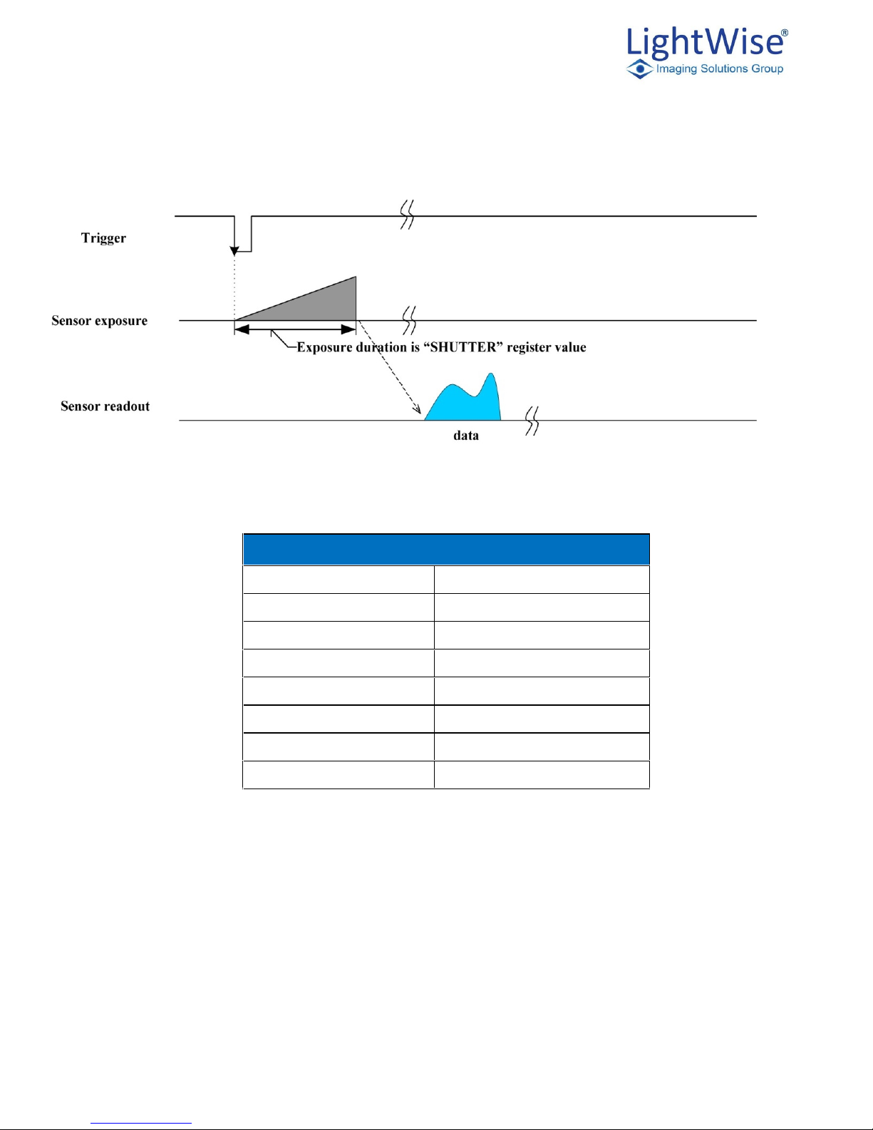
Burst Mode Trigger (Level Detect)
In this trigger mode sensor triggers will be generated as long as the input trigger is active. NOTE: Depending
on the sensor, the maximum frame rate in triggered mode may not be the same as in continuous mode.
Figure 7.3: Trigger Mode 15 (“Multi-Shot Trigger Mode”)
Exposure duration is shutter register value
Sensor
Exposure
Sensor
Readout
Frames are generated while trigger is active
ISG Allegro LightWise USB 3.0 Technical Manual Version 1.3.1
39
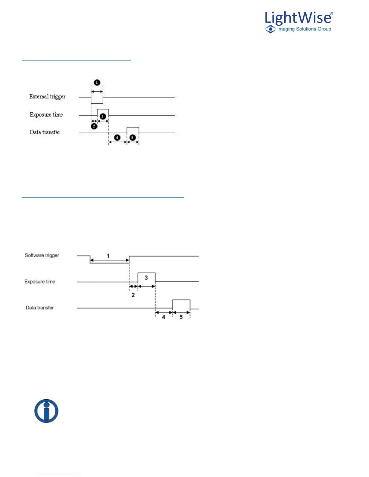
External Trigger Timing
The time from the external trigger firing to the start of shutter is shown below:
1. Trigger Pulse
2. Propagation Delay
3. Exposure Time
4. Sensor Readout
5. Data Transfer
Figure 7.4: External trigger timing characteristics
Asynchronous Software Triggering
Shutter integration can be initiated by a software trigger by setting the Trigger Source to Software in the
GenICam features.
The time from a software trigger initiation to the start of shutter is shown below:
1. Software Trigger
2. Trigger Latency
3. Exposure Time
4. Sensor Readout
5. Data Transfer
Figure 7.6: Software trigger timing
The time from when the software trigger is written on the camera to when the start of integration occurs can
only be approximated. We then add the trigger latency (time from the trigger pulse to the start of integration) to
this.
This timing is solely from the camera perspective. It is virtually impossible to predict timing
from the user perspective due to latencies in the processing of commands on the host PC

ISG Allegro LightWise USB 3.0 Technical Manual Version 1.3.1
40
9. LightWise Allegro USB 3.0 Attributes
Pixel Formats
The pixel formats describe the encoding scheme of the pixels in the camera output images. Pixel formats
describe each pixel in terms of color encoding, bit depth and formatting within the data stream.
Pixel formats conform to the GenICam Pixel Format Naming Convention (PFNC) v2.0. The full
PFNC can be found on the EMVA.org website and contains more details than provided below.
Not all features are available on all cameras.
The camera sensor Analog to Digital Converter (ADC) produces pixels at a particular bit depth, typically 10
bits. If the selected pixel format has fewer bits than the ADC output, the least significant bits are dropped. If the
selected pixel format has more bits per pixel than the ADC, the least significant bits are padded with zeros.
Mono
Mono formats include Mono8 (8 bit per pixel) and Mono10p (10 bits per pixel). Mono cameras only output
these formats. Selecting a Mono format bypasses image processing fe atures and thus offers the highest frame
rates available.
RGB
Color sensors using a Bayer color filter array support Bayer pixel formats. The camera supports BayerLM8 and
BayerLM10p. Where L and M are one of R, G, or B and describe the ordering of pixels within the Bayer pattern
(see the PFNC document). These formats require the host software to reconstruct a full color image. The color
processing in the camera is bypassed when a Bayer format is selected offering the highest available frame rate.
YCrCb/YUV
This format consists of a brightness (luma) component, Y, and color (chroma) components Cb and Cr (also
referred to as U and V). So called YCC444 format is 24 bits per pixel. Subsampling the chroma channels allows
YCbCr data to use 16 bits per pixel for a faster transfer rate without significant visual difference. This is
referred to as YCC422.

ISG Allegro LightWise USB 3.0 Technical Manual Version 1.3.1
41
Image Format Control
Name
Display Name
Description
Value
Width
Width
Width of the image provided
by the device (in pixels)
Min = 8
Max = Sensor Dependent
Height
Height
Height of the image provided
by the device (in pixels
Min = 4
Max = Sensor Dependent
Offset X
X Offset
Horizontal offset from the
origin to the region of interest
(in pixels)
Min = 0
Max =
Offset Y
Y Offset
Vertical offset from the origin
to the region of interest (in
pixels)
Min = 0
Max =
PixelFormat
Pixel Format
Format of the pixels provided
by the device. It represents all
the information provided by
PixelCoding, PixelSize,
PixelColorFilter combined in a
single feature
Monochrome Formats
Mono8, Mono10p
Color Formats
Bayer8, Bayer10p, RGB8,
YCC444, YCC422
RegionSelector
Region Selector
Selects region of interest
(ROI) to control. Region0
represents a read-only
composite image constructed
from all of the enabled ROI
regions.
0-16
RegionMode
Region Mode
Controls whether the selected
region of interest (ROI) is
active and streaming
Off = 0
On = 1

ISG Allegro LightWise USB 3.0 Technical Manual Version 1.3.1
42
Shutter Types
Global Shutter
For each frame in cameras with a global shutter sensor the start and stop time for exposure is the same. The length
of time for exposure is also the same.
For cameras with a global shutter sensor, for each frame all of the lines start and stop exposure at the same
time. The exposure time for each line is the same. Following exposure, data readout begins. The readout time
for each line is the same but the start and end times are staggered.
Increased uniform brightness and minimal motion blur are some advantages of global shutter.

ISG Allegro LightWise USB 3.0 Technical Manual Version 1.3.1
43
Rolling Shutter
For each frame in cameras with a rolling shutter sensor the exposure for each line begins at an offset equal the
readout time for each line. While the exposure time for each line is the same, the start and stop times are
staggered. Each line’s data readout begins immediately following the exposure. Readout time for each line has
the same length but staggered start and stop times.
Increase sensitivity is one of the advantages of rolling shutter, however due to the varying start times
throughout the frame, there are known artifacts such as skew, wobble and partial exposure. Please see
rolling for additional information.

ISG Allegro LightWise USB 3.0 Technical Manual Version 1.3.1
44
Rolling Shutter with Global Reset
For each frame in cameras with a rolling shutter with global reset, the lines have the exposure start time while
the stop time for exposure is delayed by the offset of the previous line’s readout. For each line the exposure
time gradually lengthens and data readout begins immediately following the line’s exposure. While the readout
time for each line is the same, the start and stop times are staggered.
The reduction in image artifacts such as skew and wobble that can be typical of rolling shutters is an advantage
of the global reset feature. However, due to increased exposure length throughout each frame there may be an
increase in brightness moving from top to bottom on an image.

ISG Allegro LightWise USB 3.0 Technical Manual Version 1.3.1
45
10. GenICam Features
Features that control, monitor and query camera operation are included in the XML device description file on the
camera. Since not all operations can be controlled using the XML file those not included are controlled via CSRs.
Except where noted, these features conform to the GenICam Standard Features NamingConvention (SFNC)
v1.5. The full SFNC can be found on the EMVA.org website and contains more details than provided below.
Not all features are available on all cameras.
Device Control
Device control features provides general information and control for the device (camera) and its sensor
Name
Display Name
Description
Value(s)
DeviceVendorName
Vendor Name
Name of the manufacturer of the device
Imaging
Solutions
DeviceFamilyName
Family Name
Identifier of the product family of the
device
LightWise
Allegro
DeviceModelName
Model Name
Model of the Device
LightWise
Allegro
USB 3.0
DeviceSerialNumber
Serial Number
Serial number of the device
DeviceVersion
Hardware Version
Version of the Hardware’s device
DeviceFirmwareVersion
Firmware Version
Device’s firmware version
DeviceUserID
User ID
User-programmable device identifier.
Acquisition must be disabled in order
to write this value
DeviceManufacturerInfo
Firmware Build
Information
Manufacturer information about the
device. This consists of firmware build
information
DeviceSFNCVersionMajor
SFNC Major Version
Major version of the Standard Features
Naming Convention that was used to
create the device`s GenICam XML
2
DeviceSFNCVersionMinor
SFNC Minor Version
Minor version of the Standard Features
Naming Convention that was used to
create the device`s GenICam XML
1
DeviceSFNCVersionSubMinor
SFNC Subminor Version
Sub minor version of the Standard
Features Naming Convention that was
used to create the device`s GenICam
XML
0
DeviceManifsetXMLMajorVersion
XML Major Version
Indicates the major version number of
the GenICam XML file of the selected
manifest entry
0
DeviceManifsetXMLMinorVersion
XML Minor Version
Indicates the minor version number of
the GenICam XML file of the selected
manifest entry
4
DeviceManifsetXMLSubMinorVersion
XML Subminor Version
Indicates the subminor version number
of the GenICam XML file of the
selected manifest entry
0
DeviceGenCPVersionMajor
GenCP Major Version
Major version of the GenCP protocol
supported by the device

ISG Allegro LightWise USB 3.0 Technical Manual Version 1.3.1
46
DeviceGenCPVersionMinor
GenCP Minor Version
Minor version of the GenCP protocol
supported by the device
DeviceU3VVersionMajor
U3V Major Version
Major version of the USB3 Vision
protocol supported by the device
DeviceU3VVersionMinor
U3V Minor Version
Minor version of the USB3 Vision
protocol supported by the device
DeviceTemperatureSelector
Temperature Reading
Source
Selections the location within the
device where temperature will be
measured
DeviceTemperature
Temperature (°C)
Device temperature in degrees Celsius
(°C). It is measured at the location
selected by DeviceTemperatureSelector
C
DeviceTemperatureFahrenheit
Temperature (°F)
Device temperature in degrees
Fahrenheit (°F). It is measured at the
location selected by
DeviceTemperatureSelector
F
DeviceLogLevel
Log Level
Selects verbosity of device log entries
0
DeviceReset
Reset Device
Resets the device to its power-up state
ColumnCorrectionEnable
Column FPN Correction
Enable column FPN correction
On = 1
Off = 0
RowCorrectionEnable
Row FPN Correction
Enable row FPN correction
On = 1
Off = 0
PixelDefectCorrectionEnable
Pixel Defect Correction
Enable pixel defect correction
On = 1
Off = 0
ControllerBoardVersionBootstrap
OTP Controller Board
Version #
One-time programmable field to store
controller board hardware revision
string

ISG Allegro LightWise USB 3.0 Technical Manual Version 1.3.1
47
Image Format Control
Name
Display Name
Description
Value
Width
Width
Width of the image provided
by the device (in pixels)
Min = 8
Max = Sensor Dependent
Height
Height
Height of the image provided
by the device (in pixels
Min = 4
Max = Sensor Dependent
Offset X
X Offset
Horizontal offset from the
origin to the region of interest
(in pixels)
Min = 0
Max =
Offset Y
Y Offset
Vertical offset from the origin
to the region of interest (in
pixels)
Min = 0
Max =
PixelFormat
Pixel Format
Format of the pixels provided
by the device. It represents all
the information provided by
PixelCoding, PixelSize,
PixelColorFilter combined in a
single feature
Monochrome Formats
Mono8, Mono10p
Color Formats
Bayer8, Bayer10p, RGB8,
YCC444, YCC422
BinningHorizontal
Binning Horizontal
Number of horizontal photosensitive cells to combine
together
Min = 1
Max = 4
BinningVertical
Binning Vertical
Number of vertical photosensitive cells to combine
together
Min = 1
Max = 4
BinningAverage
Binning Average
Controls whether the binned
pixels are summed or
averaged
On = 1
Off = 0
RegionSelector
Region Selector
Selects region of interest
(ROI) to control. Region0
represents a composite image
constructed from all of the
enabled ROI regions.
0-16
RegionMode
Region Mode
Controls whether the selected
region of interest (ROI) is
active and streaming
Off = 0
On = 1

ISG Allegro LightWise USB 3.0 Technical Manual Version 1.3.1
48
Acquisition Control
Name
Display Name
Description
Value
AcquisitionMode
Acquisition Mode
Sets the acquisition mode of the
device. It defines mainly the number
of frames to capture during an
acquisition and the way the
acquisition stops
Single Frame = 0
Multi Frame = 1
Continuous = 2
AcquisitionStart
Acquisition Start
Starts the Acquisition of the device.
The number of frames captured is
specified by AcquisitionMode
AcquisitionStop
Acquisition Stop
Stops the Acquisition of the device
at the end of the current frame. It is
mainly used when AcquisitionMode
is Continuous but can be used in
any acquisition mode
TriggerSelector
Trigger Selector
Selects the type of trigger to
configure
Acquisition Start = 3
TriggerSource
Trigger Source
Specifies the internal signal or
physical input Line to use as the
trigger
Software = 0xfc
Line0 = 0
TriggerMode
Trigger Mode
Trigger source states
Off = 0
On = 1
TriggerActivation
Trigger Activation Mode
Specifies the activation mode of the
trigger
Rising Edge = 0
Falling Edge = 1
TriggerDelay
Trigger Delay
Specifies the delay in microseconds
(us) to apply after the trigger
reception before activating it.
Min = 0
Max = 67108863.0
TriggerSoftware
Generate Software Trigger
Generates an internal trigger.
TriggerSource must be set to
Software.
ExposureTime
Exposure Time
Controls the Absolute exposure time
in microseconds (µs)
Min = 100.0
Max = 10000000.0
AcquisitionFrameCount
Acquisition Frame Count
Number of frames to acquire in
MultiFrame Acquisition mode
Min = 1
Max = 32
AcquisitionMaxFrameCount
Max Acquisition Frame Count
Max number of frames that can be
acquired in MultiFrame acquisition
mode. This value is a function of
image size and pixel format
32

ISG Allegro LightWise USB 3.0 Technical Manual Version 1.3.1
49
Digital IO Control
Name
Display Name
Description
Value
LineSelector
Strobe Selector
Selects the physical line (or pin) of the
external device connector to configure
Strobe 1 = 0
Strobe 2 - 1
LineMode
Line Mode
Controls if the physical Line is used to Input
or Output a signal
Output = 1
LineInverter
Invert Strobe Output
Controls the inversion of the signal of the
selected input or output Line
Invert StrobeInput
Invert Strobe Input
Custom feature: On this device, this controls
the inversion of the signal entering the strobe
control block. This should be adjusted such
that an active-high signal enters the strobe
controller
LineSource
Strobe Source
Selects which internal acquisition or I/O
source signal to output on the selected Line.
LineMode must be Output
LineFormat
Line Format
Controls the current electrical format of the
selected physical input or output Line
Opto Coupled = 5
StrobeDelay
Strobe Delay (µs)
Controls the delay (in microseconds) of the
signal of the selected output Line
Min = 0
Max = 1000
StrobeDuration
Strobe Duration (µs)
Controls the delay (in microseconds) of the
signal of the selected output Line
Min = 0
Max = 1000

ISG Allegro LightWise USB 3.0 Technical Manual Version 1.3.1
50
Analog Control
Name
Display Name
Description
Value
GainSelector
Gain Selector
Selects which Gain is
controlled by the various Gain
features
DigitalAll = 0x40
Gain
Gain
Controls the selected gain as
an absolute physical value.
This is an amplification factor
applied to the video signal
Min = 1.0
Max = 31.99
BlackLevelSelector
Black Level Selector
Selects which Black Level is
controlled by the various
Black Level features
0
BlackLevel
Black Level
Controls the selected black
level as an integer value. This
is an offset factor subtracted
from the video signal
Min = -512
Max = 512
BalanceRatioSelector
Balance Ratio Selector
Controls the mode for
automatic white balancing
between the color channels.
The white balancing ratios are
automatically adjusted
Red = 0
Green = 1
Blue = 1
BalanceRatio
White Balance Ratio
Controls ratio of the selected
color component to a
reference color component. It
is used for white balancing
Min = 0
BalanceWhiteAuto
Auto White Balance
Controls the mode for
automatic white balancing
between the color channels.
The white balancing ratios are
automatically adjusted.
Off = 0
Once = 1
Saturation
Saturation
Controls the Saturation
Control Coefficient
Min = 0.1
Max = 7.9
SaturationEnable
Saturation Enable
Enables the Saturation
Off = 0
On = 1
Gamma
Gamma
Controls the gamma
correction of pixel intensity
Min = .2
Max = 1.0
GammaEnable
Gamma Enable
Enables the gamma correction
of pixel intensity
Off = 0
On = 1
Transport Layer Control
Name
Display Name
Description
Value
PayLoadSize
Pay Load Size
Provides the number of bytes transferred for each
image or chunk on the stream channel. This includes
any end-of-line, end-of-frame statistics or other stamp
data. This is the total size of data payload for a data
block
CurrentSpeed
Current Speed
Current speed of USB bus
Low Speed = 0
Full Speed = 1
High Speed = 2
Super Speed = 3

ISG Allegro LightWise USB 3.0 Technical Manual Version 1.3.1
51
User Set Control
Name
Display Name
Description
Value
UserSetSelector
User Set Selector
Select the feature user set to
load, save, or configure
0
UserSetLoad
Load Selected User Set
Loads the User Set specified
by UserSetSelector and makes
it active
UserSetSave
Save Selected User Set
Save the User Set specified by
UserSetSelector to the nonvolatile memory of the device
UserSetDefault
Default User Set
Select the feature user set to
load and make active by
default when the device is
reset

ISG Allegro LightWise USB 3.0 Technical Manual Version 1.3.1
52
11. Trouble Shooting
 Loading...