

Page 1
User’s Guide
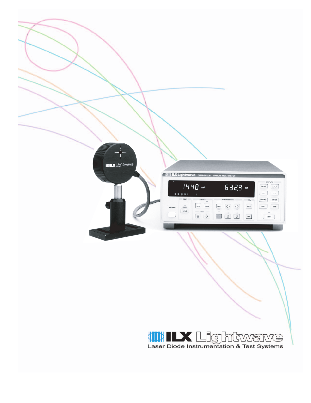
Silicon Power / Wavehead
OMH-6722B
ILX Lightwave Corporation · P. O. Box 6310 · Bozeman, MT, U.S.A. 59771 · U.S. & Canada: 1-800-459-9459 · International Inquiries: 406-556-2481 · Fax 406-586-9405
ilx.custhelp.com · www.ilxlightwave.com
70023303_R00_03_03
Page 2

Page 3

TABLE OF CONTENTS
TABLE OF CONTENTS
SafetyandWarrantyInformation ...............................vii
SafetyInformationandtheManual.................................vii
GeneralSafetyConsiderations....................................vii
SafetySymbols ............................................viii
SafetyMarkingSymbols ........................................viii
Warranty.................................................. ix
Comments,Suggestions,andProblems ............................xi
Chapter 1 Introduction and Specifications
Product Overview ............................................1
SafetyConsiderations...........................................1
AvailableOptionsandAccessories ................................ 2
Specifications ...............................................3
Chapter 2 Operation
Installation .................................................5
Power-Up ..................................................6
Front Panel Controls . . .......................................6
UnusedFunctions .............................................. 7
ErrorDisplay .................................................. 7
RearPanelConnections ......................................... 7
4_03 OMH-6722B i
Page 4

TABLE OF CONTENTS
InputConnector ...............................................7
AnalogOutput ................................................. 8
General Operating Procedures .................................9
Warm-upandEnvironmentalConsiderations ......................... 9
BeamAlignmentConsiderations .................................. 9
DivergingBeams(LaserDiodes)................................ 10
CollimatedBeams ........................................... 10
FocusedBeams............................................. 10
FiberOpticCable............................................ 10
MeasuringorSettingtheWavelength.............................. 10
Zeroing .....................................................11
UserCalibration .............................................. 12
Installing Fiber Optic Adapters .................................13
CareandMaintenance .......................................13
Cleaning .................................................... 13
Chapter 3 Command Reference
Introduction ................................................15
Common Commands . . ......................................15
Device-Dependent Commands . . . . . . . . . . . ........................ 15
Error Messages ............................................16
ProgrammingExamples ........................................ 16
Chapter 4 Calibration
CalibrationOverview ........................................19
RecommendedEquipment ...................................... 19
Warm-up .................................................... 19
Manual Operation User Calibration . . ...........................20
Remote(GPIB)OperationUserCalibration .......................20
Programming a Fixed Offset to Wavelength and Power Measurements . 21
ii OMH-6722B
ResettingtheUserCalibration .................................21
Page 5

Chapter 5 Troubleshooting
Introduction ................................................23
Troubleshooting Guide . ......................................23
TABLE OF CONTENTS
4_03 OMH-6722B iii
Page 6

TABLE OF CONTENTS
iv OMH-6722B
Page 7

LIST OF FIGURES
LIST OF FIGURES
Figure 2.1 OMM-6810B Front Panel .........................6
Figure 2.2 Rear Panel Input ................................7
Figure 2.3 PowerAnalogOut ...............................8
Figure 2.4 OMH-6722B Optical Measurement Head .............9
Figure 2.5 WavelengthSetting .............................10
Figure 3.1 CommandPathStructure ........................18
4_03 OMH-6722B v
Page 8

LIST OF FIGURES
vi OMH-6722B
Page 9

LIST OF TABLES
LIST OF TABLES
Table 3.1 Device-Dependent Commands valid with the OMH-6722B 17
Table 3.2 Device-Dependent Commands which are not usable
with the OMH-6722B 18
4_03 OMH-6722B vii
Page 10

LIST OF TABLES
viii OMH-6722B
Page 11

SAFETY AND WARRANTY INFORMATION
The Safety and Warranty Information section provides details about cautionary
symbols used in the manual, safety markings used on the instrument, and
information about the Warranty including Customer Service contact information.
Safety Information and the Manual
Throughout this manual, you will see the words Caution and Warning indicating
potentially dangerous or hazardous situations which, if not avoided, could result in
death, serious or minor injury, or damage to the product. Specifically:
Caution indicates a potentially hazardous situation which can result in minor or
moderate injury or damage to the product or equipment.
Warning indicates a potentially dangerous situation which can result in serious injury or
death.
WARNING
Visible and/or invisible laser radiation. Avoid direct exposure to the beam.
General Safety Considerations
If any of the following conditions exist, or are even suspected, do not use the
instrument until safe operation can be verified by trained service personnel:
• Visible damage
• Severe transport stress
• Prolonged storage under adverse conditions
• Failure to perform intended measurements or functions
If necessary, return the instrument to ILX Lightwave, or authorized local ILX
Lightwave distributor, for service or repair to ensure that safety features are
maintained (see the contact information on page xiii).
All instruments returned to ILX Lightwave are required to have a Return
Authorization Number assigned by an official representative of ILX Lightwave
Corporation. See Returning an Instrument on page xi for more information.
OMH-6722B ix
Page 12
SAFETY SYMBOLS
SAFETY SYMBOLS
This section describes the safety symbols and classifications.
Technical specifications including electrical ratings and weight are included within
the manual. See the Table of Contents to locate the specifications and other
product information. The following classifications are standard across all ILX
Lightwave products:
• Indoor use only
• Ordinary Protection: This product is NOT protected against the harmful ingress of moisture.
• Class I Equipment (grounded type)
• Mains supply voltage fluctuations are not to exceed ±10% of the nominal supply voltage.
• Pollution Degree II
• Installation (overvoltage) Category II for transient overvoltages
• Maximum Relative Humidity: <80% RH, non-condensing
• Operating temperature range of 0 °C to 40 °C
• Storage and transportation temperature of –40 °C to 70 °C
• Maximum altitude: 3000 m (9843 ft.)
• This equipment is suitable for continuous operation.
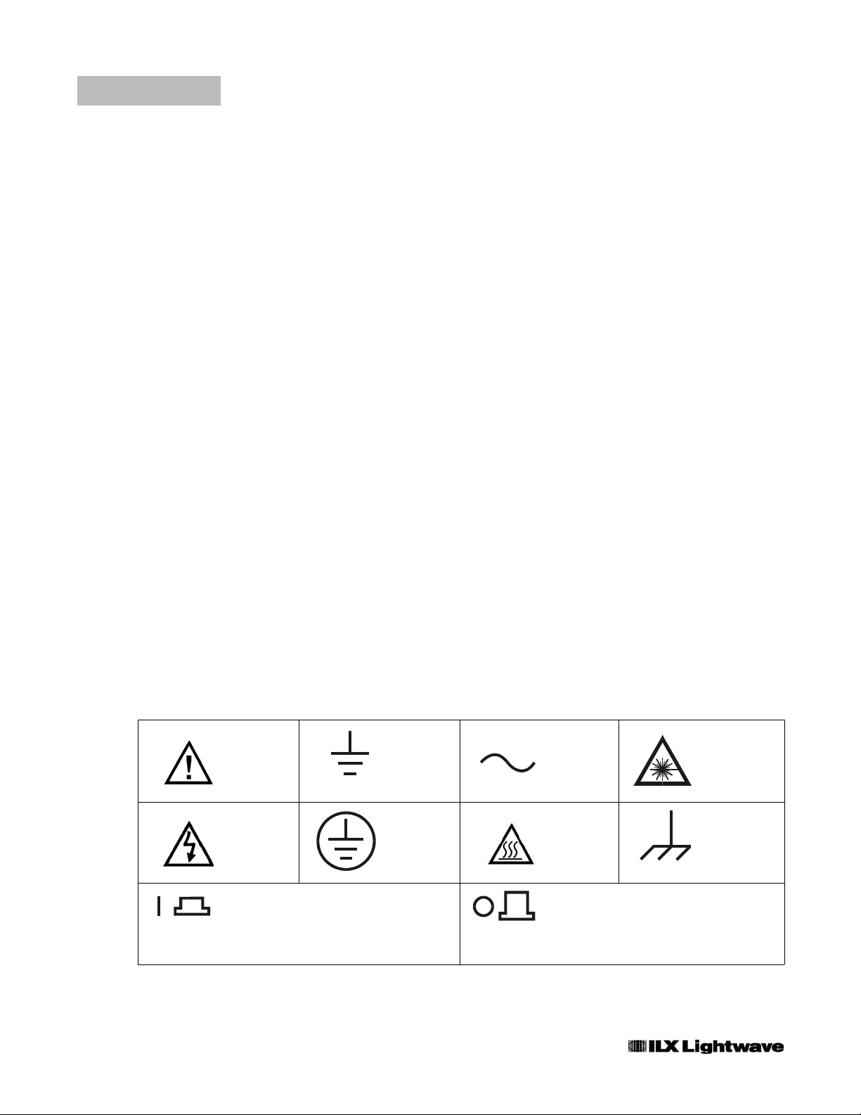
Safety Marking Symbols
This section provides a description of the safety marking symbols that appear on
the instrument. These symbols provide information about potentially dangerous
situations which can result in death, injury, or damage to the instrument and other
components.
Caution,
refer to
manual
Caution, risk
of electric
shock
On: In position of a bistable push control.
The slash (I) only denotes that mains are on.
or
(I)
Earth
ground
Te r mi n a l
Protective
Conductor
Te r mi n a l
Alternating
current
Caution, hot
surface
Off: Out position of a bistable push control.
The circle (O) only denotes that mains are off.
or
(O)
Visible and/or
invisible laser
radiation
Frame or
chassis
Te rm in a l
x OMH-6722B
Page 13

WARRANTY
ILX LIGHTWAVE CORPORATION warrants this instrument to be free from
defects in material and workmanship for a period of one year from date of
shipment. During the warranty period, ILX will repair or replace the unit, at our
option, without charge.
Limitations
This warranty does not apply to fuses, lamps, defects caused by abuse,
modifications, or to use of the product for which it was not intended.
This warranty is in lieu of all other warranties, expressed or implied, including any
implied warranty of merchantability or fitness for any particular purpose. ILX
Lightwave Corporation shall not be liable for any incidental, special, or
consequential damages.
WAR RAN TY
If a problem occurs, please contact ILX Lightwave Corporation with the
instrument's serial number, and thoroughly describe the nature of the problem.
ReturninganInstrument
If an instrument is to be shipped to ILX Lightwave for repair or service, be sure to:
1 Obtain a Return Authorization number (RA) from ILX Customer Service.
2 Attach a tag to the instrument identifying the owner and indicating the required service or
repair. Include the instrument serial number from the rear panel of the instrument.
3 Attach the anti-static protective caps that were shipped with the instrument and place the
instrument in a protective anti-static bag.
4 Place the instrument in the original packing container with at least 3 inches (7.5 cm) of
compressible packaging material. Shipping damage is not covered by this warranty.
5 Secure the packing box with fiber reinforced strapping tape or metal bands.
6 Send the instrument, transportation pre-paid, to ILX Lightwave. Clearly write the return
authorization number on the outside of the box and on the shipping paperwork. ILX
Lightwave recommends you insure the shipment.
If the original shipping container is not available, place your instrument in a
container with at least 3 inches (7.5 cm) of compressible packaging material on all
sides.
Repairs are made and the instrument returned transportation pre-paid. Repairs
are warranted for the remainder of the original warranty or for 90 days, whichever
is greater.
4_03 OMH-6722B xi
Page 14

WAR RAN TY
Claims for Shipping Damage
When you receive the instrument, inspect it immediately for any damage or
shortages on the packing list. If the instrument is damaged, file a claim with the
carrier. The factory will supply you with a quotation for estimated costs of repair.
You must negotiate and settle with the carrier for the amount of damage.
xii OMH-6722B
Page 15

WAR RAN TY
Comments, Suggestions, and Problems
To ensure that you get the most out of your ILX Lightwave product, we ask that
you direct any product operation or service related questions or comments to ILX
Lightwave Customer Support. You may contact us in whatever way is most
convenient:
Phone ........................... (800)459-9459or(406)586-1244
Fax............................................. (406)586-9405
Onthewebat: ....................................ilx.custhelp.com
Or mail to:
ILX Lightwave Corporation
P. O . B o x 6 3 1 0
Bozeman, Montana, U.S.A 59771
www.ilxlightwave.com
When you contact us, please have the following information:
Model Number:
Serial Number:
End-user Name:
Company:
Phone:
Fax:
Descriptionofwhatis
connected to the ILX
Lightwave instrument:
Description of the problem:
If ILX Lightwave determines that a return to the factory is necessary, you are
issued a Return Authorization (RA) number. Please mark this number on the
outside of the shipping box.
You or your shipping service are responsible for any shipping damage when
returning the instrument to ILX Lightwave; ILX recommends you insure the
shipment. If the original shipping container is not available, place your instrument
4_03 OMH-6722B xiii
Page 16

WAR RAN TY
in a container with at least 3 inches (7.5 cm) of compressible packaging material
on all sides.
We look forward to serving you even better in the future!
xiv OMH-6722B
Page 17

CHAPTER 1
INTRODUCTION AND SPECIFICATIONS
This manual contains operation and maintenance information for the OMH-6722B
Silicon Power / Wave Head. The OMH-6722B may be used in conjunction with
either the OMM-6810B Optical Multimeter or the LWM-6500B Laser Wavelength
Meter. To get started immediately, first read Appendix B of the OMM-6810B
Instruction Manual.
Product Overview
The OMH-6722B Silicon Power/WaveHead, when coupled to an OMM-6810B
Optical Multimeter, provides the capability to accurately measure the power and
wavelength of laser sources between 400 and 1100 nm. The OMH-6722B is
calibrated to NIST traceable power and wavelength standards to ensure accuracy.
The OMH-6722B can also be used with the LWM-6500B to measure wavelength
only.
Easy mounting, quick setup and alignment, and a two meter cable make the ILX
Lightwave Optical Measurement Head easy to integrate into an experiment. The
instrument can be integrated with other equipment via the optional GPIB/IEEE-
488.2 interface. The 6722B can also be used for fiber optic measurement
applications via an optional fiber optic adapter.
Safety Considerations
The high brightness, sometimes invisible light output of laser diodes and other
laser sources poses a definite eye hazard. Direct viewing of the laser output can
produce retinal or corneal damage. Absorption of the laser light by the eye
causes localized heating and denaturing of tissue proteins. The ANSI publication
Z-136.1, "The Safe Use of Lasers", lists Maximum Permissible Exposure (MPE)
levels for direct, or intrabeam viewing of laser beams. From the MPE levels, a
"hazard zone" may be computed for a particular laser and exposure time.
OMH-6722B 1
Page 18

CHAPTER 1
Available Options and Accessories
INTRODUCTION AND SPECIFICATIONS
Product Overview
For more information concerning lasers and laser diode safety, contact the Center
for Devices and Radiological Health or ILX Lightwave.
Refer Servicing only to qualified, authorized personnel.
The OMH-6722B must be coupled to the OMM-6810B Optical Multimeter.
Other options and accessories available with the OMM-6810B are listed in the
OMM-6810B manual.
2 OMH-6722B
Page 19
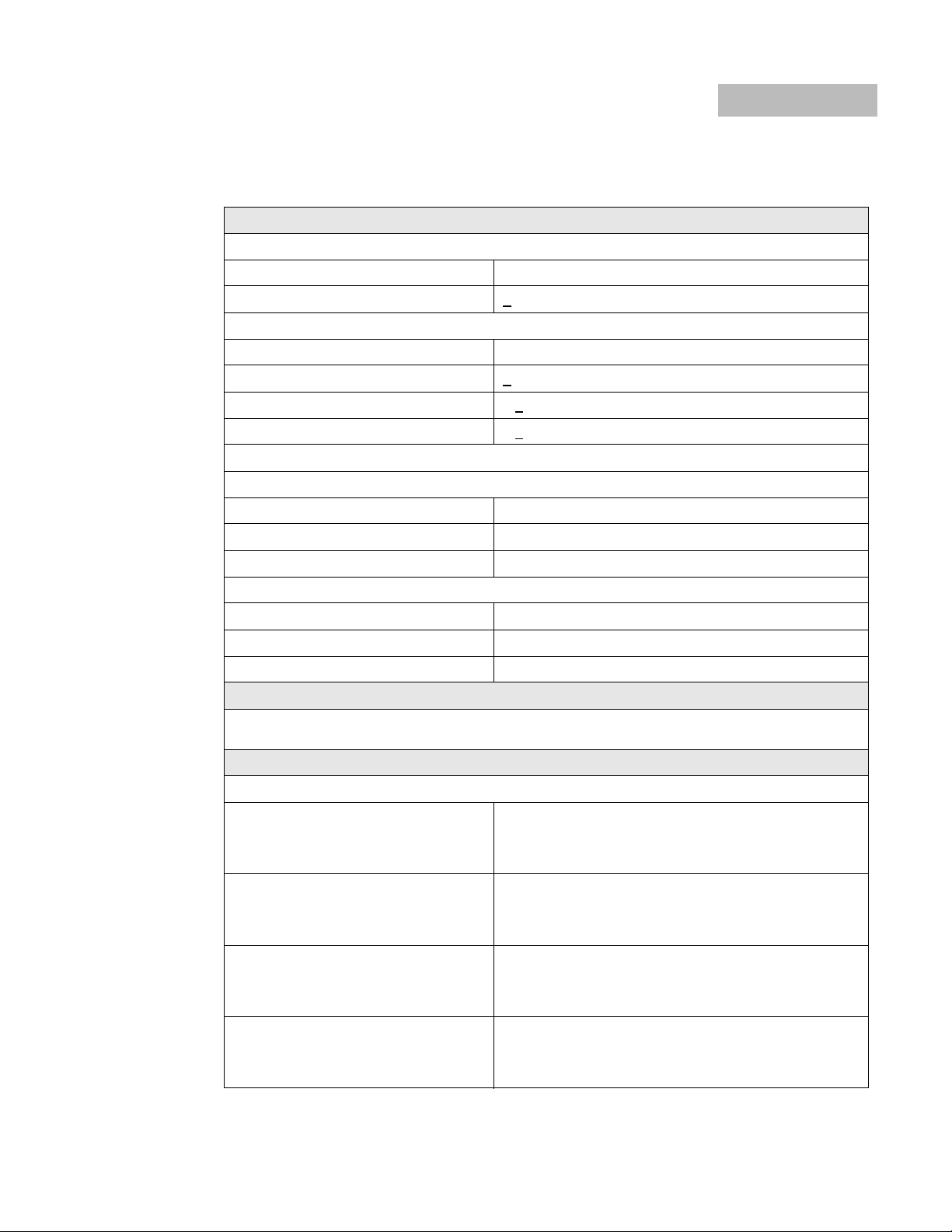
Specifications
Input Specifications
Power Measurement
Range 100 nW ~ 1 W
Accuracy +3.5% (450 to 990 nm)
Wavelength Measurement
Range 400 to 1100 nm
Accuracy + 1.0 nm
Temperature coefficient < + 0.03 nm /oC
INTRODUCTION AND SPECIFICATIONS
Specifications
2
; -40 dBm ~ + 30 dBm
1,3,4
2
3
CHAPTER 1
2
Linearity with power change < +
(Maximum change in measured wavelength due to power change)
Sampling Rate
Slow 16 samples @ 60 ms / sample
Medium 4 samples @ 60 ms / sample
Fast 1 sample @ 60 ms / sample
Input Bandwidth
Slow 1 Hz
Medium 10 Hz
Fast 60 Hz
Analog Output Specifications
Analog output representing the power measurement is available at the rear panel of the multimeter.
Refer to the OMM-6810B Instruction Manual for details.
Display
Left Display (Power)
Units
Linear Power
Log Power
Range
Linear Power
Log Power
0.5 nm
pW, nW, µW, mW, W,
dBm, dB
0.000 nW to 999.999 W
-99.999 to 99.999 dBm / dB
∆P
Resolution (Slow Update Rate)
Linear Power
Log Power
Resolution (Medium / Fast Update Rate)
Linear Power
Log Power
4_03 OMH-6722B 3
0.001 pW
0.001 dB
0.01 pW
0.01 dB
Page 20
CHAPTER 1
INTRODUCTION AND SPECIFICATIONS
Specifications
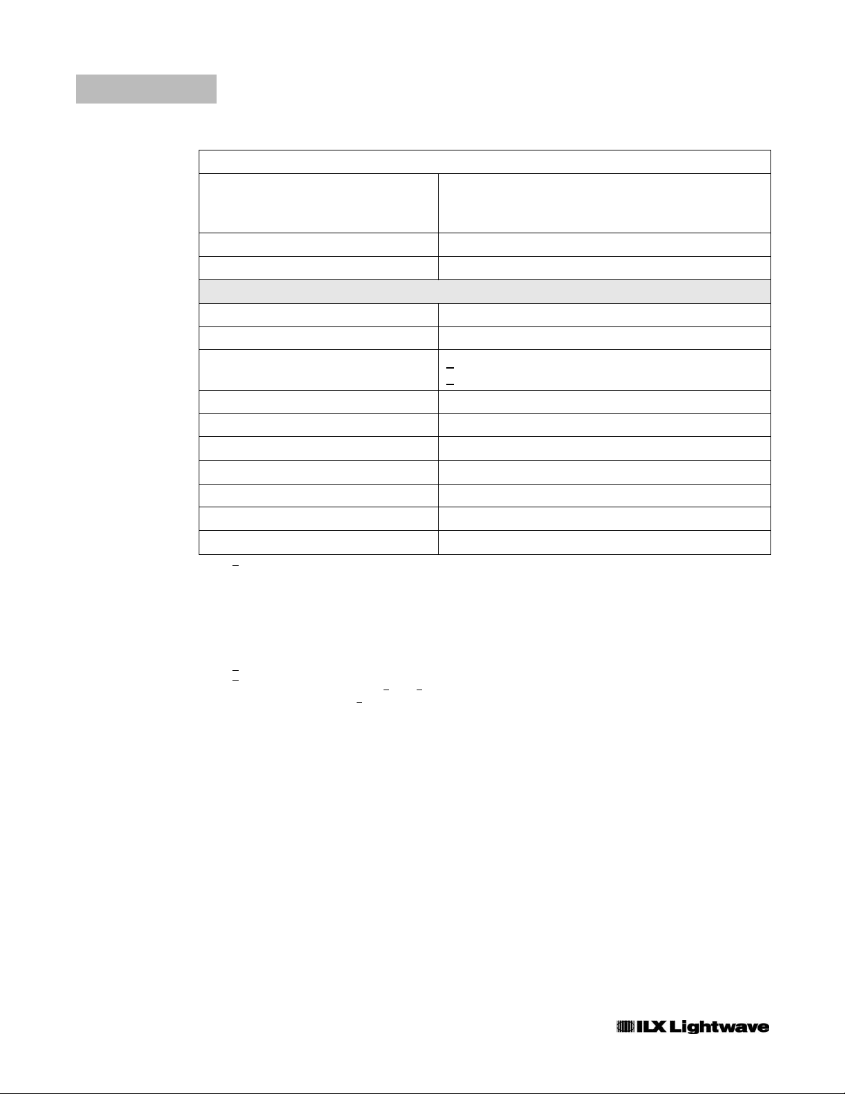
Right Display (Wavelength)
-1
Units
Range
Resolution
Bargraph Percent of full scale power
Brightness 5 settings
General Specifications
Operating Temperature + 15
Storage Temperature -40
Humidity (non-condensing) >
Overall Dimensions 68.6 mm diameter x 30.1 mm
Weight < 0.5 kg
Input Port Diameter 6 mm
Input Type Integrating sphere
nm, cm
500.0 to 1000.0 nm, 20,000 to 10,000 cm
.1 nm, .1 cm-1Right Display (Wavelength)
o
100 µW: <85% RH
<
100 µW: <70% RH
, ∆λ
o
Cto+35oC
Cto+70oC
-1
Optical Stand Accommodations 8/32 tapped hole centered
Fiber Optic Adapter FC, SC, ST
Connector to Main Unit 26 pin high-density sub-D
1. Add + 0.5% from 400 to 450 nm and from 990 to 1100 nm.
2. Minimum optical power required for accurate wavelength measurement:
400 nm ~ 500 nm
100uW(-10dBm)
500 nm ~ 1100 nm
10 uW (-20 dBm)
For power measurement below these levels, use MANUAL wavelength mode.
3. For input power > 100 mW:
Add +
0.05% / 100 mW to power accuracy
Add +
0.05 nm / 100 mW to wavelength accuracy
Example: 500 mW, 850 nm, accuracy = +
4. MANUAL wavelength mode: Add +0.5% for automatic wavelength correction.
4.2%, +1.2 nm
Our goal is to design and produce the best optical test equipment available
anywhere. To achieve this, we need your ideas and comments on ways we can
improve out products. We invite you to contact us at any time with your
suggestions.
4 OMH-6722B
Page 21

CHAPTER 2
OPERATION
This chapter describes how to install and operate the OMH-6722B Silicon
Power/WaveHead in conjunction with a OMM-6810B Optical Multimeter. It is
divided into sections covering installation, power-up, front panel and rear panel
controls, and general operation. A detailed familiarization of the main unit
features are presented in Chapter 2 of the OMM-6810B Instruction Manual.
Installation
The OMH-6722B must be connected to the 6810B. Make sure the power to the
main unit is turned off and connect the cable from the 6722B to the INPUT
connector on the rear panel of the 6810B.
Do not attach or remove the Optical Measurement Head while power is applied to the
OMM-6810B. Please turn the power switch off when changing heads.
To avoid electrical shock hazard, connect the meter to a properly earth grounded, three
prong receptacle only. Failure to observe this precaution can result in severe
injury or death.
OMH-6722B 5
Page 22
CHAPTER 2
Power-Up
OPERATION
Power-Up
Connect the main unit to an AC power source. Press the POWER switch to
supply power to the device and start the power-up sequence.
The power-up sequence takes about six seconds. Initially, all LEDs and
enunciators are illuminated and the seven-segment displays denote "8". Then, all
LEDs and the displays are turned off while the microprocessor executes a device
self-test. Should the self test fail, error message E-720 is displayed. The Meter
then loads personality and calibration data from the measurement head. The left
display indicates -6722- and the firmware version is shown on the right display. If
an error occurs while loading data, message E-711 is displayed. If an
incompatible head is connected, error message E-713 is shown. If the
measurement head is not connected the display shows "------" until a
measurement head is attached.
At power up the main unit is configured to the same state that was present when
the power was last turned off.
Front Panel Controls
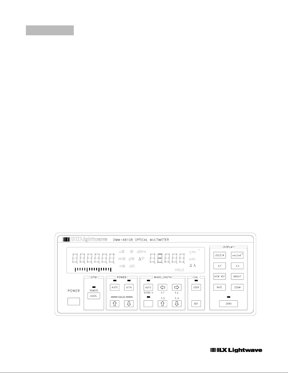
The OMM-6810B/OMH-6722B is intuitively operated from the front panel keypad,
indicator LEDs and dual displays. A drawing of the front panel is shown in Figure
2.1. Front panel functions which are not available with the OMH-6722B are
outlined later in this Chapter.
Refer to the OMM-6810B Instruction Manual for descriptions of each front panel
switch function.
6 OMH-6722B
Figure 2.1 OMM-6810B Front Panel
Page 23
OPERATION
Front Panel Controls
Unused Functions
The Multimeter function that is not utilized (disabled) when
the OMH-6722B is attached are shown to the right. If a
disabled button is pushed, the 6810B will display the error
code E-715.
All other switch functions perform as described in the OMM-6810B Instruction
Manual.
CHAPTER 2
Error Display
Execution errors are indicated on the right display. Errors are shown as "E-xxx"
where xxx is a three digit number representing the unique error. Errors are
displayed for three seconds or until the error causing condition is remedied,
whichever is longer. See Appendix A in the OMM-6810B Instruction Manual for a
detailed list of error messages.
Rear Panel Connections
The OMH-6722B interfaces with the rear panel of the multimeter as described in
the following paragraphs.
Input Connector
The OMH-6722B interfaces the Multimeter via the 26-pin high density “D”
connector located on the lower left side of the rear panel. Do not attach or remove
the head while power is applied to the Optical Multimeter. Please turn the power
switch off when changing optical measurement heads.
INPUT
Figure 2.2 Rear Panel Input
4_03 OMH-6722B 7
Page 24
CHAPTER 2
Analog Output
OPERATION
Front Panel Controls
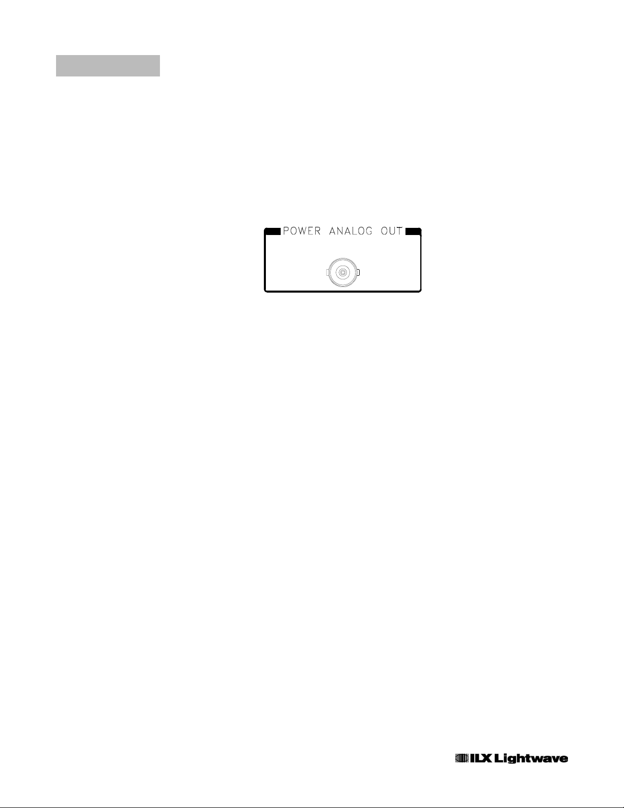
Analog output representing the power measurement is located in the upper left
corner of the 6810B rear panel. The
value between 0 and 10 volts representing the measured power as a percent of
full scale power within the selected gain range. For example, if the full scale power
for gain range three is 10
is present on the
POWER ANALOG OUT connector.
µW and the displayed power is 5.000 µW, then 5.0 volts
Figure 2.3 Power Analog Out
POWER ANALOG OUT is a non-calibrated
8 OMH-6722B
Page 25
OPERATION
General Operating Procedures
General Operating Procedures
The following sections present some guidelines for operating the OMM-6810B
with the OMH-6722B. More detailed instructions are found in the OMM-6810B
Instruction Manual. Remote operation is discussed in Chapter 4.
Warm-up and Environmental Considerations
The main unit and Optical Measurement Head should operate at an ambient
temperature between 10 and 35
Storage temperatures should be between -40 and +70
stability, let both devices warm up for at least one hour.
Beam Alignment Considerations
The OMH-6722B is designed to provide a simple operating format. The beam
from the source should be directed perpendicular to the face of the 6722B and
directly into its aperture. Be sure the entrance angle does not exceed the
specified
± 10° from perpendicular.
°C and a relative humidity less than 70%.
°C, To achieve rated
CHAPTER 2
Be aware that certain lasers emit a significant amount of non-lasing radiation.
This radiation can cause erroneous measurements if the source is placed too
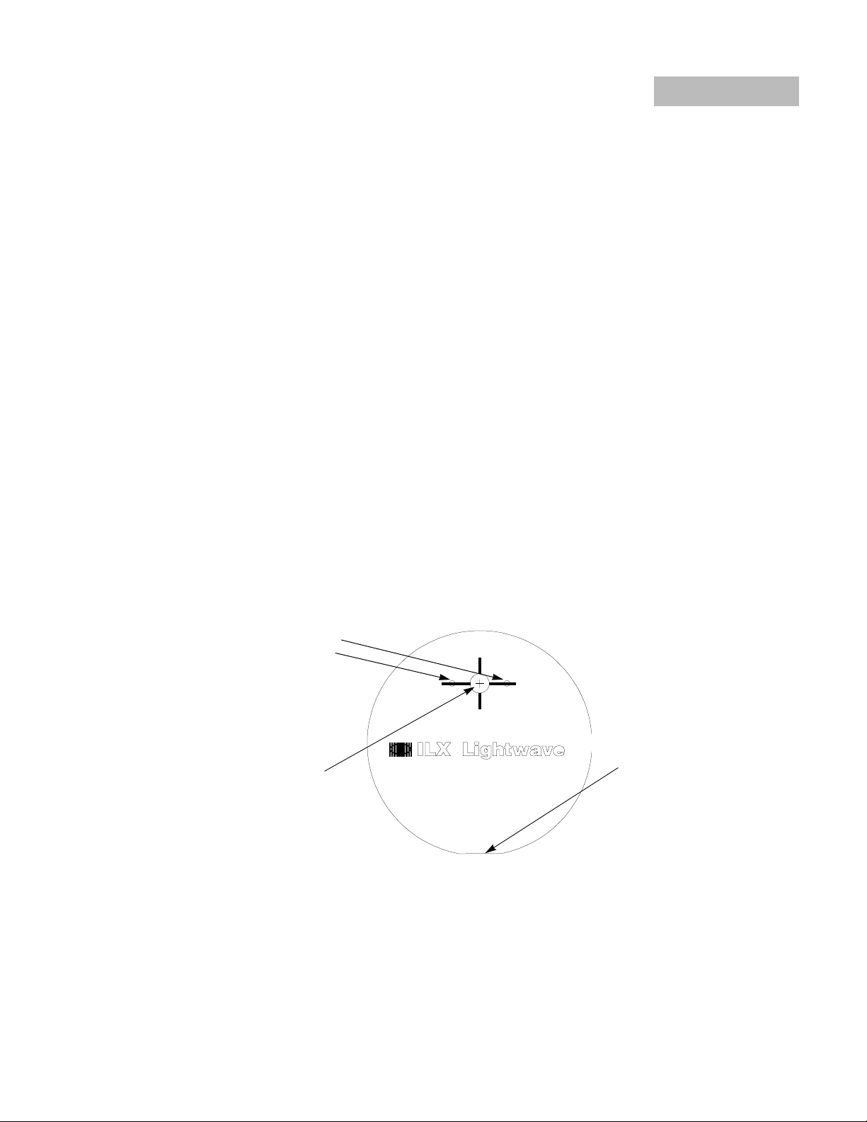
close to the measurement head. The innovative ILX Optical Measurement Head
offers easy access for many different source types:
Fiber Optic Adapter
Mounting Holes
Aperture
Figure 2.4 OMH-6722B Optical Measurement Head
#8−32 Post Mount,
Centered
4_03 OMH-6722B 9
Page 26

CHAPTER 2
OPERATION
General Operating Procedures
Diverging Beams (Laser Diodes)
The OMH-6722B can measure the wavelength and power of laser diodes without
the need for complicated coupling optics. For low powered lasers and laser
diodes, position the package as close as possible to the 6722B to insure that all of
the light enters the integrating sphere.
Collimated Beams
The OMH-6722B is capable of measuring the wavelength and power of narrow
beam lasers. As with other lasers, collimated beams should enter the aperture
perpendicular to the face of the 6722B. To maintain accuracy, do not allow the
beam to strike the edge of the entrance aperture.
Focused Beams
The OMH-6722B also accepts converging beams. In high power applications be
sure that the focus of the beam does not occur at the rear of the integrating
sphere. Again, perpendicular beam entry to the Head is required.
Fiber Optic Cable
A fiber optic adapter (options AO271, AO272, AO273, and AO276,) can be
mounted onto the face of the OMH-6722B Measurement Head. This threaded
ring/adapter cap option accepts a variety of fiber optic connector styles for direct
coupling of a fiber optic cable to the head.
Measuring or Setting the Wavelength
For automatic wavelength compensation of power measurements, press the
WAVELENGTH
wavelength of the source can also be manually programmed into the OMM-6810B
using the procedure below.
AUTO button so that the indicator above the button is lighted. The
Figure 2.5 Wavelength Setting
10 OMH-6722B
Page 27

OPERATION
General Operating Procedures
• Use the WAVELENGTH LEFT and RIGHT arrow buttons to select the digit on the
Wavelength display that will be controlled by the WAVELENGTH UP and DOWN arrow
buttons. The selected digit will flash.
• Use the WAVELENGTH UP and DOWN arrow buttons to increment or decrement the
selected digit. If no buttons are pressed in three seconds, the displayed wavelength will be
locked in and the digit will stop flashing.
• Commonly used wavelengths may be stored or retrieved by using the WAVELENGTH BLUE
SHIFT, STORE λ, λ1,λ2,λ3, and λ4 buttons as described in Chapter 2 of the OMM-6810B
manual.
Zeroing
The ZERO function is used to remove the effects that
erroneous room light has on the wavelength and power
measurement. It is important to zero the OMM-6810B with the
OMH-6722B attached before taking measurements. This is
especially true for low input power applications or in cases of
high ambient light intensity. When measuring lower power
levels, avoid letting background radiation into the measurement head.
CHAPTER 2
Pressing the DISPLAY
lighted starts the zeroing process. While zeroing the "0" digit
displays and the DISPLAY
DISPLAY
ZERO indicator is illuminated. Pressing the DISPLAY ZERO button
when the DISPLAY
ZERO button when the DISPLAY ZERO indicator is not
walks across both
ZERO indicator flashes. When zeroing is complete the
ZERO indicator is illuminated disables the effects of the zero.
The procedure for zeroing the instrument is described below.
• The beam from the optical source should be blocked at the source or turned off.
Note: If a beam stop is used, it should be positioned as close to the source as possible to
allow the
OMH-6722B is blocked instead, the zeroing function will not work properly. This is
especially true for low power applications or in areas of high background light.
• If the DISPLAY ZERO indicator is illuminated, press the DISPLAY ZERO button once to
disable the existing compensation factors.
• Press the DISPLAY ZERO button. While zeroing, the "0" digit walks across the display and
the DISPLAY ZERO indicator flashes. When zeroing is complete the DISPLAY ZERO
indicator is lighted. The process takes about 15 seconds.
• Allow the beam to enter the aperture of the head. Accurate measurements are displayed.
Note: If the ambient environmental conditions change, e.g. the room lights are turned on or
off, the instrument must be re-zeroed to maintain its accuracy.
• Pressing the DISPLAY ZERO button again disables the compensating factors and the
DISPLAY ZERO indicator is turned off.
maximum collection of background "noise". If the entry aperture to the
4_03 OMH-6722B 11
Page 28

CHAPTER 2
User Calibration
OPERATION
General Operating Procedures
It is possible to calibrate the OMH-6722B using a laser source of
known power and wavelength. The calibration procedure is
described in Chapter 6 of this manual.
Press the CAL
of the User Calibration Mode. When the LED above the CAL
USER button is lighted, the unit employs the user defined
calibration which has been stored in the Optical Measurement
Head. Pressing the CAL
LED is lighted causes the instrument to revert to factory calibration and the LED to
go out. Pressing the CAL
is lighted initiates the user calibration procedure.
USER button to toggle the instrument in and out
USER button when the CAL USER
SET button while the LED above the CAL USER button
12 OMH-6722B
Page 29

OPERATION
Installing Fiber Optic Adapters
Installing Fiber Optic Adapters
Use the following procedure to install Fiber Optic Adapters onto the OMH-6722B
Measurement Head.
• Locate the model AO270 threaded ring adapter and the two #2-56 X 3/16” cap screws that
secure it to the Measurement Head.
• Place the adapter onto the face of the Measurement Head and secure it using the two cap
screws.
CHAPTER 2
• The adapter is now ready to receive any AOXXX series screw on fiber optic adapter cap, e.g
AO271 (FC). Screw the cap on until it bottoms out on the face of the Measurement Head.
Care and Maintenance
The design of the Measurement Head is fairly robust, however it should be
handled with care. Stress from dropping the Head or other mishandling could
dislodge critical alignments within the Head, effectively changing its response and
nullifying its calibration. It is also sensitive to electrostatic discharge. When not in
use, replace the ESD-protective cap that came with the Head on the D connector
and store the Head in the ESD-safe bag.
Cleaning
In general, avoid cleaning the interior of the Measurement Head, especially by
blowing into it or by using compressed air.
have entered the input aperture
nitrogen. Use short bursts while holding the head such that the aperture is
directed downward.
, remove the contaminant using canned air or dry
If minor dust or other particulates
4_03 OMH-6722B 13
Page 30

CHAPTER 2
OPERATION
Care and Maintenance
14 OMH-6722B
Page 31

CHAPTER 3
COMMAND REFERENCE
Introduction
This chapter is a guide to the usage of the device-dependent GPIB commands for
the OMM-6810B Optical Multimeter when the OMH-6722B Silicon Power Head is
attached. This chapter is of primary interest to users who wish to utilize the GPIB
option. A complete reference describing the syntax and usage of each devicedependent command is provided in Chapter 4 of the OMM-6810B Instruction
Manual. Refer to the LWM-6500B Instruction Manual if the OMH-6722B is being
used in conjunction withe the Laser Wavelength Meter.
Common Commands
The GPIB Common Commands which are defined by the ANSI/IEEE-488.2-1987
standard are described in Chapter 3 of the OMM-6810B Instruction Manual.
These commands do not necessarily reflect front panel operations and are not
unique to the measurement head connected to the meter. In other words, the
common commands listed in the 6810B Instruction Manual are all valid when
using the OMH-6722B.
Device-Dependent Commands
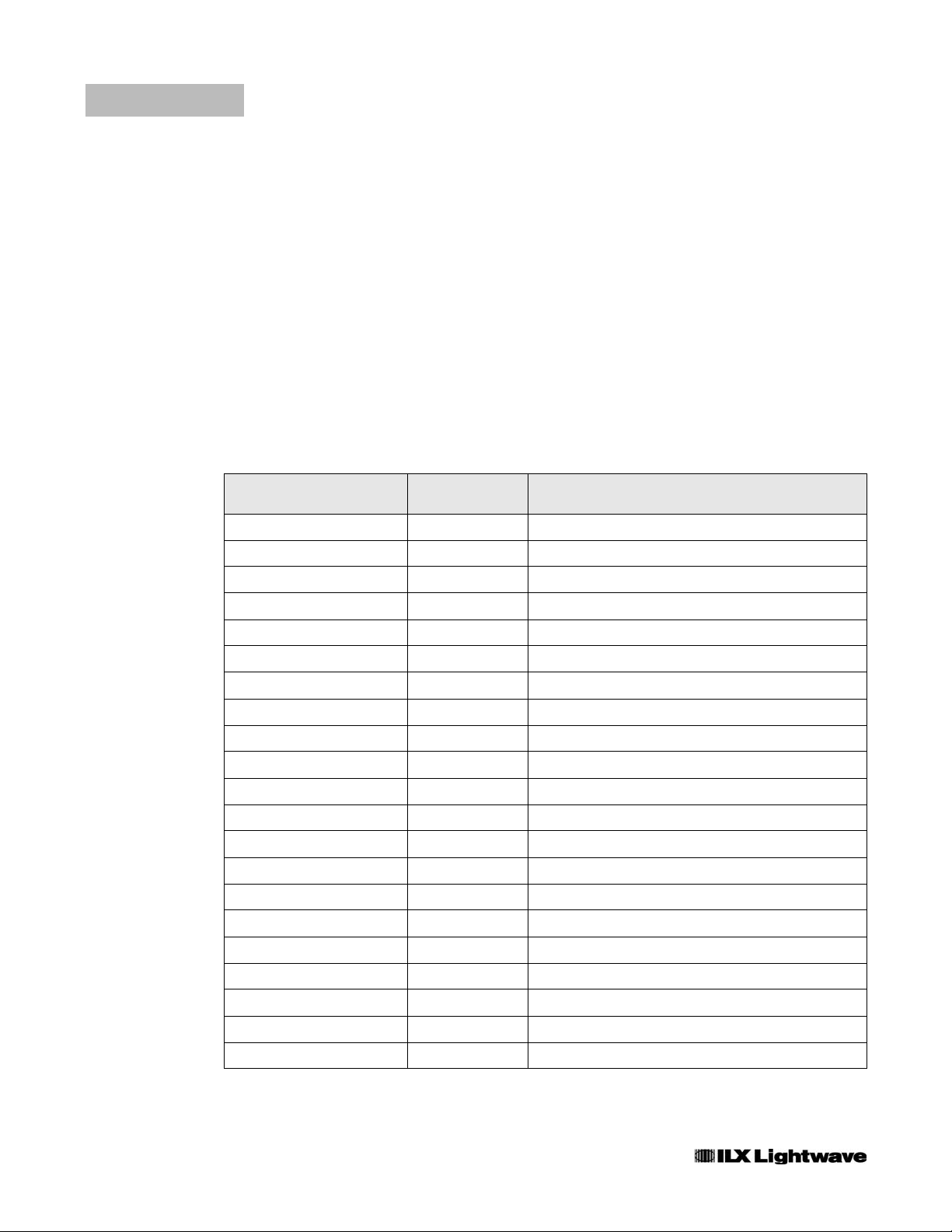
Chapter 4 of the OMM-6810B Instruction Manual contains the complete set of
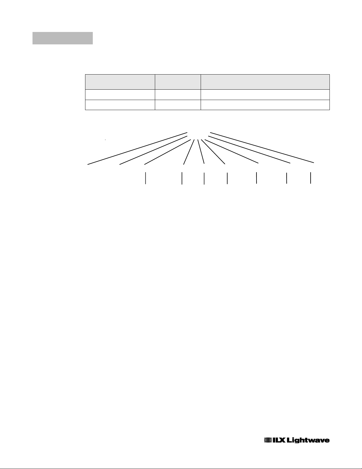
device-dependent GPIB commands. Table 4.1 on the next page outlines the
subset of commands which are valid when the OMH-6722B is attached. The
command path
Note: The usage and syntax of each device dependent command is best described in
Chapter 4 of the OMM-6810B Optical Multimeter Instruction Manual.
tree structure is illustrated in Figure 4.1.
OMH-6722B 15
Page 32
CHAPTER 3
COMMAND REFERENCE
Error Messages
Error Messages
Error messages may appear on the right display. In remote operation, the current
error list can be read by issuing the
returned containing the previously unread error messages (up to ten). When the
error queue is active, bit #7 of the Status Byte is also set to one.
Appendix A of the OMM-6810B Instruction Manual contains an explanation of the
error messages which may be reported by the 6810B on the display or via remote
operation.
Programming Examples
Two examples of programming the 6810B via GPIB are shown in the 6810B
Instruction Manual, Chapter 4.
ERR? query. When this is done, a string is
Command Name # Parameters
Expected
BRIght 1 Sets the brightness of the front panel
BRIght? None Returns the level of the display brightness
CAL: POWERSET 2 Sets the user calibration power
CAL: RECall None Resets the user calibration
CAL:USER None Starts the user calibration
COND? None Returns the condition status register
ENAB:COND 1 Sets the enable register for conditions
ENAB:COND? None Returns the condition enable register
ENAB:EVENT 1 Sets the enable register for events
ENAB:EVENT? None Returns the event enable register
ERRors? None Returns errors generated since last ERR?
EVEnt? None Returns the event status register
HEAD:IDN? None Returns the head identification string
HOLD? None Returns the hold status
POWer? None Returns the power measurement
POWer:AUTO 1 Sets the power autoranging mode on or off
Description
16 OMH-6722B
POWer:AUTO? None Returns the status of power autoranging
POWer:MODE 2 Sets the power display units
POWer:MODE? None Returns the power display units
POWer:OFFSET 1 Sets the power offset multiplier
POWer:OFFSET? None Returns the power offset multiplier
Page 33

COMMAND REFERENCE
Error Messages
CHAPTER 3
POWer:REFerence 2 Sets the reference for AP measurements
POWer:REFerence? None Returns the power reference level
PREselect:CHAN 1 Selects on of four preselected wavelengths
PREselect:CHAN? None Returns the preselected wavelength channel
being used
PREselect:SAVE 2 Sets one of the four preselected wavelengths
RANge 1 Sets the gain range (manual)
RANge? None Returns the gain range (auto/manual)
RANge:AUTO 1 Sets the autoranging mode on or off
RANge:AUTO? None Returns the status of the autoranging
RATE 1 Sets the measurement rate
RATE? None Returns the measurement rate string
SECURE 1 Used by service personnel to access PUB
TERM 1 Sets the program message terminator
TERM? 1 Returns the program message terminator
TIME? None Returns elapsed time since power up
TIMER? None Returns elapsed time since last TIMER?
WAVE 2 Sets the wavelength
WAVE? None Returns the set wavelength
WAVE:AUTO 1 Sets the auto wavelength feature on or off
WAVE:AUTO? None Returns the status of auto wavelength
WAVE:MODE 1 Sets the wavelength display units
WAVE:MODE? None Returns the wavelength display units
WAVE:OFFSET 2 Sets the wavelength offset
WAVE:OFFSET? None Returns the wavelength offset
WAVE:REFerence 2 Sets the reference for
∆λ
WAVE:REFerence? None Returns the wavelength reference point
ZERO None Starts the zeroing function
ZERO? None Returns the status of the zeroing.
Table 3 . 1 Device-Dependent Commands valid with the OMH-6722B
1
1
4_03 OMH-6722B 17
Page 34
CHAPTER 3
COMMAND REFERENCE
Error Messages
Command Name # Parameters
Expected
ATTen 1 Enables/disables the attenuation function
ATTen? None Returns the status of the attenuator
Description
Table 3 . 2 Device-Dependent Commands which are not usable with the OMH-6722B
(root)
*CAL?
*CLS
*DLF
*ESE
*ESE?
*ESR?
*IDN?
*IST
*OPC
*OPC?
*PRE
*PRE?
*PSC
*PSC?
*PUD
*PUD?
*RST
*SRE
*SRE?
*STB?
*TST?
*WAI
BRIGHT
BRIGHT?
COND?
ERR?
EVE?
HOLD?
POWER?
RANGE
RANGE?
RATE
RATE?
SECURE
TERM
TERM?
TIME?
TIMER?
TRIGGER
TRIGGER?
WAVE
WAVE?
ZERO
ZERO?
:CAL
POWERSET
RECALL
USER
WAVESET
:ENAB
COND
COND?
EVE
EVE?
:HEAD
IDN?
:POWER
AUTO
AUTO?
MODE
MODE?
OFFSET
OFFSET?
REF
REF?
:PRESELECT
CHAN
CHAN?
SAVE
:RANGE
AUTO
AUTO?
:WAVE
AUTO
AUTO?
MODE
MODE?
OFFSET
OFFSET?
REF
REF?
18 OMH-6722B
Figure 3.1 Command Path Structure
Page 35

CHAPTER 4
CALIBRATION
This chapter describes how to calibrate the OMH-6722B Silicon
Power/WaveHead.
The OMH-6722B Silicon Power/WaveHead has been sealed to protect internal components
from damage and to maintain the factory calibration. Do not attempt to disassemble the
Optical Measurement Head.
Calibration Overview
It is possible to calibrate the OMH-6722B using a source of known wavelength
and power. Calibrate the 6722B whenever performance verification indicates that
calibration is necessary. The wavelength calibration consists of one point which
shifts future measurements by the amount of the calibration. The power
calibration consists of one point which changes future power measurements by
the percentage calculated during the calibration.
Recommended Equipment
It is recommended that gas-line sources, not laser diodes, be used for calibration.
Ideal sources include gas lasers, such as HeNe at 632.8 nm, and spectral lamps
with the proper line isolation filters, such as a Cesium Lamp and a 845 nm - 855
nm interference filter to isolate the 852.1 nm Cesium emission line. Laser diodes
should not be used since current and temperature can affect the output
wavelength. An extremely stable laser diode may be used if it is lasing in a single
mode and the wavelength is first measured with a calibrated optical spectrum
analyzer.
Warm-up
Before attempting calibration, the OMH-6722B should be allowed to warm up for
at least 1 hour after being connected to the main unit.
OMH-6722B 19
Page 36

CHAPTER 4
CALIBRATION
Manual Operation User Calibration
Manual Operation User Calibration
Front Panel execution of the User Calibration using the OMM-6810B is described
in the procedure below:
• Identify ambient conditions and zero the instrument as described in Section 2.6.4.
• Launch a laser of known wavelength and power into the OMH-6722B.
• Start the calibration by pressing the CAL USER button to place the unit in User Calibration
Mode. The LED above the CAL USER button will light. Press the CAL SET button to initiate
the User Calibration Procedure. The left display will show "CAL-λ".
• The measured wavelength is shown on the right display. Adjust the displayed wavelength to
match the laser's known wavelength using the WAVELENGTH LEFT and RIGHT buttons to
select a digit and then use the WAVELENGTH UP and DOWN arrow buttons to change the
wavelength.
• Press the CAL SET button to complete the wavelength calibration.
• The right display will now indicate “CAL-P”. The measured power will be shown on the left
display. Adjust the displayed power to match the laser’s known power using the POWER UP
and DOWN arrow buttons. If large adjustments are necessary, hold down the UP or DOWN
button to accelerate the change.
• Press the CAL SET button to complete the calibration. The unit returns to real time
wavelength and power measurements.
Remote (GPIB) Operation User Calibration
Remote controlled User Calibration is described in the following procedure. It
may help to be familiar with the manual calibration in Section 6.3 before
attempting it remotely.
• Identify ambient conditions. Block the laser beam from entering the aperture of the OMH6722B.
• Start the calibration by clearing the status registers, then zeroing the instrument by issuing
the following GPIB commands:
*CLS
RANGE:AUTO ON
ZERO
• Wait for the zero to finish. The controlling software can monitor the status of zeroing by
sending the following query in a loop. Exit the loop when the response is '1'.
ZERO?
• Launch a laser of known wavelength and power into the aperture of the 6722B. Start the
calibration by sending the following commands.
CAL:USER ON
20 OMH-6722B
CAL:USER START
Page 37

CALIBRATION
Programming a Fixed Offset to Wavelength and Power Measurements
• Enter the known wavelength using the command:
CAL:WAVESET xxxx.xx ss
where, xxxx.xx is the known wavelength and ss is the units (µm, nm or cm).
• Enter the known power using the command:
CAL:POWERSET xxxx.xx ss
where, xxxx.xx is the known power and ss is the units (pw, nw, µw, mw, w or dbm).
• The calibration is complete and the 6810B is performing real time wavelength and power
measurements.
Programming a Fixed Offset to Wavelength and Power
Measurements
Rather than performing a User Calibration it is possible to enter offset values
which are applied to future wavelength and power measurements. For more
information refer the
Chapter 4 of the OMM-6810B Instruction Manual.
POWER:OFFSET and WAVE:OFFSET GPIB commands in
CHAPTER 4
Resetting the User Calibration
The User Calibration is preset at the factory. The factory preset calibration can be
restored by pressing the CAL
indicator is off or by sending the GPIB command CAL:USER OFF.
USER button on the 6810B so that the CAL USER
4_03 OMH-6722B 21
Page 38

CHAPTER 4
CALIBRATION
Resetting the User Calibration
22 OMH-6722B
Page 39

CHAPTER 5
TROUBLESHOOTING
Introduction
This chapter is intended to be used as a guide when the OMM-6810B and
OMH-6722B do not perform as expected. It is not a service manual, rather a
guide to alleviate basic problems which may arise during operation. A more
complete guide, including a GPIB troubleshooting guide, is provided in Chapter 7
of the OMM-6810B Instruction Manual.
Troubleshooting Guide
If you have difficulty using the 6722B, refer to the symptoms listed here. Common
causes and corrective actions are listed here. If problems persist, contact your
ILX Lightwave representative at (406) 586-1244.
OMH-6722B 23
Page 40

CHAPTER 5
TROUBLESHOOTING
Troubleshooting Guide
Symptom Causes and Corrective Actions
Measurement will not
stabilize
• The OMH-6722B is designed to accurately measure the
wavelengthofaCWsourcewithanamplitudeinstabilityofupto
40% depth of modulation. Ensure the laser source’s wavelength is
stable and that any modulation is minimized. This condition may
occur if the laser has not warmed up. Most gas laser cavities
expand when first turned on which can cause intensity and
wavelength fluctuations.
• Check for tight connections between the main unit and the 6722B
and ensure other “noisy” electronic devices are not located near
the Optical Measurement Head.
• In cases of low input power and/or high background light, try
working in a dark environment and be sure to zero the instrument
as described in Chapter 2.
Display shows "-----"
Display shows "HI-P"
• The 6722B is not connected to the main unit.
• This condition occurs when the laser’s input power exceeds the
maximum allowed for the selected gain range. Measurements at
this level are invalid. If in manual mode, press the DOWN switch
to select the next lower gain range.
Display shows “HI-
λ"
• This condition occurs when the instrument interprets the laser’s
wavelength as greater than 1100 nm which is beyond the
capability of the OMH-6722B.
Display shows “LO-
λ"
• This condition occurs when the instrument interprets the laser’s
wavelength as less than 400 nm which is beyond the capability of
the OMH-6722B.
Measurements are not
accurate at a known
wavelength or power
standard
Measurement seems erratic
with a pulsed source input
• Be certain the zeroing procedure has been performed correctly.
• It may be necessary to perform the User Calibration.
• The source may be too close to the WaveHead and is emitting
non-lasing radiation into the aperture.
• Change update rates. Best results with pulsed sources are usually
in the SLOW update rate.
• Work in MANUAL gain ranging mode; the AUTORANGING
algorithm may have difficulty with some pulsed sources, especially
those with duty cycles less than 50%.
24 OMH-6722B
 Loading...