

Page 1
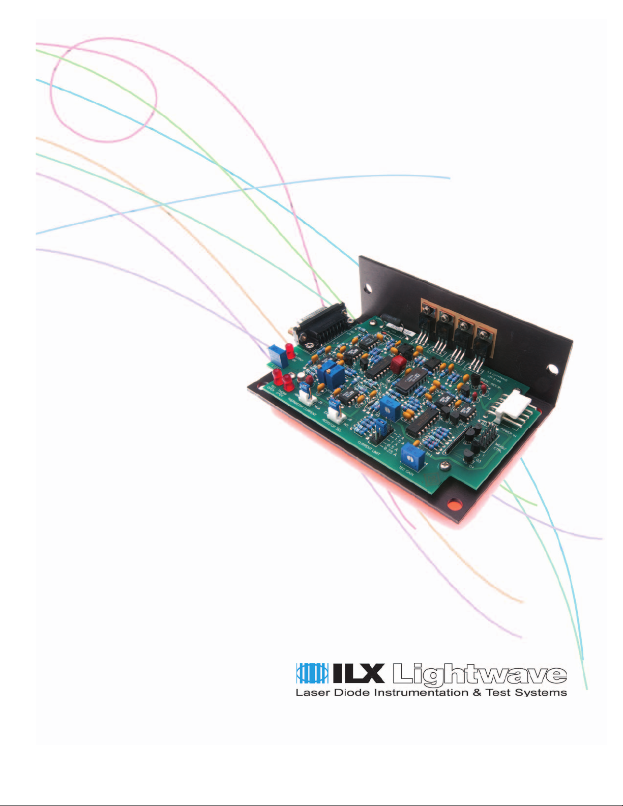
User’s Guide
Laser Diode Temperature Controller
LDX-5100
ILX Lightwave Corporation · P. O. Box 6310 · Bozeman, MT, U.S.A. 59771 · U.S. & Canada: 1-800-459-9459 · International Inquiries: 406-556-2481 · Fax 406-586-9405
ilx.custhelp.com · www.ilxlightwave.com
70014302 May 2007
Page 2

Page 3

TABLE OF CONTENTS
TABLE OF CONTENTS
Table of Contents . . . . . . . . . . . . . . . . . . . . . . . . . . . . . . . . . . . . . . . . . . . i
Safety and Warranty Information. . . . . . . . . . . . . . . . . . . . . . . . . . . . . . iii
Safety Information and the Manual . . . . . . . . . . . . . . . . . . . . . . . . . . . . . . . . . iii
General Safety Considerations . . . . . . . . . . . . . . . . . . . . . . . . . . . . . . . . . . . . iii
Safety Symbols . . . . . . . . . . . . . . . . . . . . . . . . . . . . . . . . . . . . . . . . . . . . . . . . . .iv
Safety Marking Symbols . . . . . . . . . . . . . . . . . . . . . . . . . . . . . . . . . . . . . . . . . iv
Warranty . . . . . . . . . . . . . . . . . . . . . . . . . . . . . . . . . . . . . . . . . . . . . . . . . . . . . . . . v
Limitations . . . . . . . . . . . . . . . . . . . . . . . . . . . . . . . . . . . . . . . . . . . . . . . . . . v
Returning an Instrument . . . . . . . . . . . . . . . . . . . . . . . . . . . . . . . . . . . . . . . v
Claims for Shipping Damage . . . . . . . . . . . . . . . . . . . . . . . . . . . . . . . . . . . . vi
Comments, Suggestions, and Problems . . . . . . . . . . . . . . . . . . . . . . . . . . . .vii
Chapter 1 Introduction
Product Overview . . . . . . . . . . . . . . . . . . . . . . . . . . . . . . . . . . . . . . . . . . . . . . . . 2
Thermoelectric Temperature Control . . . . . . . . . . . . . . . . . . . . . . . . . . . . . . . 2
Specifications
1
. . . . . . . . . . . . . . . . . . . . . . . . . . . . . . . . . . . . . . . . . . . . . . . . . . . 3
Chapter 2 Operation
Thermistor Resistance Set Point . . . . . . . . . . . . . . . . . . . . . . . . . . . . . . . . . . . . 5
Internal . . . . . . . . . . . . . . . . . . . . . . . . . . . . . . . . . . . . . . . . . . . . . . . . . . . . . . 5
External . . . . . . . . . . . . . . . . . . . . . . . . . . . . . . . . . . . . . . . . . . . . . . . . . . . . . . 5
Thermistor Current Source . . . . . . . . . . . . . . . . . . . . . . . . . . . . . . . . . . . . . . . . 6
Current Limit (J4) . . . . . . . . . . . . . . . . . . . . . . . . . . . . . . . . . . . . . . . . . . . . . . . . 6
05_07 LDT-5100 i
Page 4

TABLE OF CONTENTS
TEC Gain . . . . . . . . . . . . . . . . . . . . . . . . . . . . . . . . . . . . . . . . . . . . . . . . . . . . . . . 6
Measurement/Control (J2) . . . . . . . . . . . . . . . . . . . . . . . . . . . . . . . . . . . . . . . . . 6
Output Off . . . . . . . . . . . . . . . . . . . . . . . . . . . . . . . . . . . . . . . . . . . . . . . . . . . . 6
Output Monitors . . . . . . . . . . . . . . . . . . . . . . . . . . . . . . . . . . . . . . . . . . . . . . . 7
Thermistor Monitor . . . . . . . . . . . . . . . . . . . . . . . . . . . . . . . . . . . . . . . . . . . . 7
TE Drive Current Monitor . . . . . . . . . . . . . . . . . . . . . . . . . . . . . . . . . . . . . . . 7
Status Monitors . . . . . . . . . . . . . . . . . . . . . . . . . . . . . . . . . . . . . . . . . . . . . . . . 7
Thermistor Open (pin 6) . . . . . . . . . . . . . . . . . . . . . . . . . . . . . . . . . . . . . . . . 7
TEC Open (pin 4) . . . . . . . . . . . . . . . . . . . . . . . . . . . . . . . . . . . . . . . . . . . . . 7
Output On/Off (pin 2) . . . . . . . . . . . . . . . . . . . . . . . . . . . . . . . . . . . . . . . . . . 8
LED Indicators . . . . . . . . . . . . . . . . . . . . . . . . . . . . . . . . . . . . . . . . . . . . . . . . . . . 8
TEC I/O Connector (J1) . . . . . . . . . . . . . . . . . . . . . . . . . . . . . . . . . . . . . . . . . . . . 8
DC Power-In Connector (J3) . . . . . . . . . . . . . . . . . . . . . . . . . . . . . . . . . . . . . . . . 8
Chapter 3 Calibration
Thermistor Current Source Calibration . . . . . . . . . . . . . . . . . . . . . . . . . . . . . . . 9
TE Current Limit Calibration . . . . . . . . . . . . . . . . . . . . . . . . . . . . . . . . . . . . . . . 9
ii LDT-5100
Page 5

S
AFETY AND
Safety Information and the Manual
W
ARRANTY INFORMATION
The Safety and Warranty Information section provides details about cautionary
symbols used in the manual, safety markings used on the instrument, and
information about the Warranty including Customer Service contact information.
Throughout this manual, you will see the words Caution and Warning indicating
potentially dangerous or hazardous situations which, if not avoided, could result in
death, serious or minor injury, or damage to the product. Specifically:
Caution indicates a potentially hazardous situation which can result in minor or
moderate injury or damage to the product or equipment.
Warning indicates a potentially dangerous situation which can result in serious injury or
death.
General Safety Considerations
If any of the following conditions exist, or are even suspected, do not use the
instrument until safe operation can be verified by trained service personnel:
• Visible damage
• Severe transport stress
• Prolonged storage under adverse conditions
• Failure to perform intended measurements or functions
If necessary, return the instrument to ILX Lightwave, or authorized local ILX
Lightwave distributor, for service or repair to ensure that safety features are
maintained (see the contact information on page vii). All instruments returned to
ILX Lightwave are required to have a Return Authorization Number assigned by
an official representative of ILX Lightwave Corporation. See Returning an
Instrument on page v for more information.
Safety and Warranty Information iii
Page 6
SAFETY AND WARRANTY INFORMATION
Safety Symbols
SAFETY SYMBOLS
This section describes the safety symbols and classifications. Technical
specifications including electrical ratings and weight are included within the
manual. See the Table of Contents to locate the specifications and other product
information. The following classifications are standard across all ILX Lightwave
products:
• Indoor use only
• Ordinary Protection: This product is NOT protected against the harmful ingress of moisture.
• Class I Equipment (grounded type)
• Electrical Rating: 100 - 240 V; ~ 2.5A; 225W; 50/60 Hz
• Mains supply voltage fluctuations are not to exceed ±10% of the nominal supply voltage.
• Pollution Degree 2
• Installation (overvoltage) Category II for transient overvoltages
• Maximum Relative Humidity: <80% RH, non-condensing
• Operating temperature range of 10 °C to 40 °C
• Storage and transportation temperature of –40 °C to 70 °C
• Maximum altitude: 3000 m (9843 ft)
• This equipment is suitable for continuous operation.
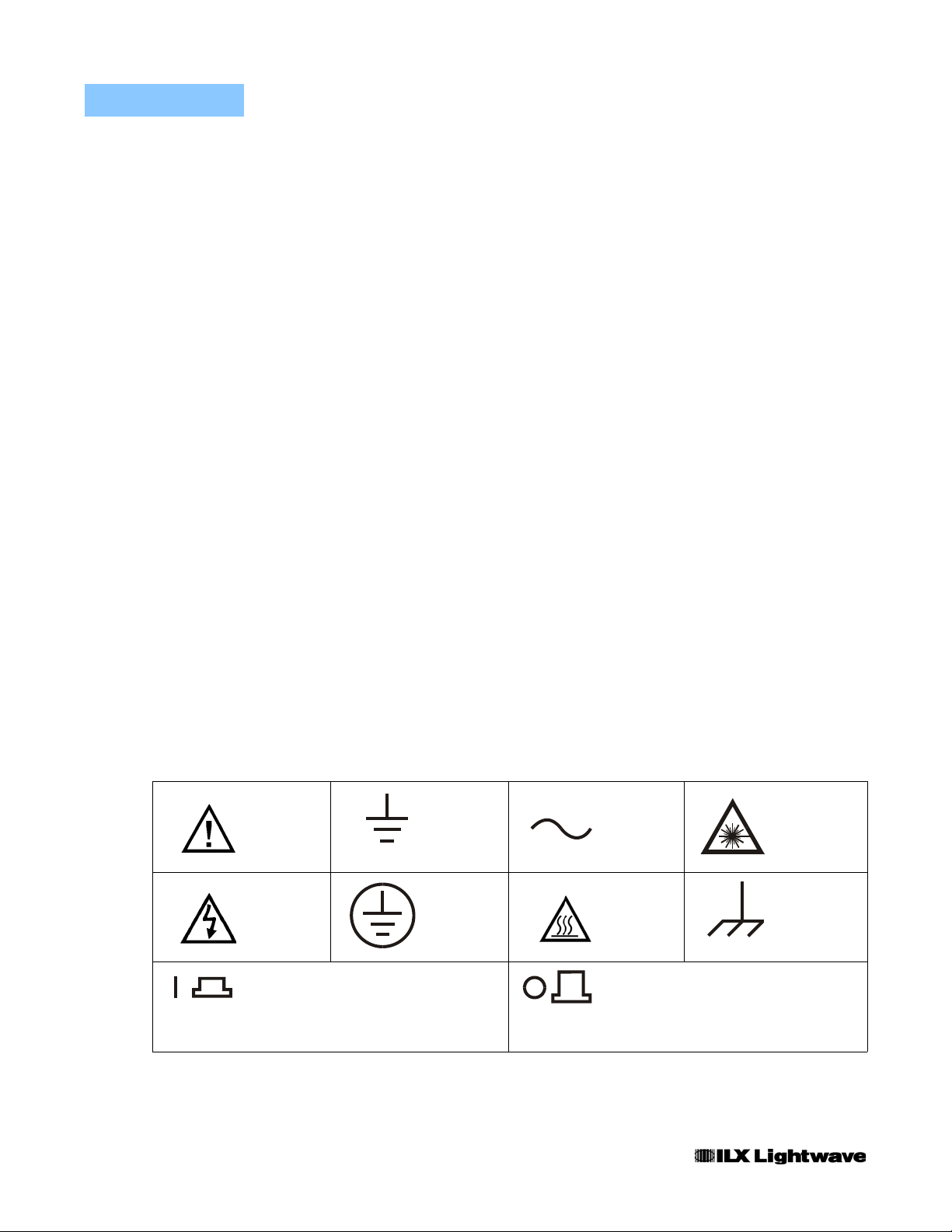
Safety Marking Symbols
This section provides a description of the safety marking symbols that appear on
the instrument. These symbols provide information about potentially dangerous
situations which can result in death, injury, or damage to the instrument and other
components.
Caution,
refer to
manual
Caution, risk
or
(I)
of electric
shock
On: In position of a bistable push control.
The slash (I) only denotes that mains are on.
Earth
ground
Te r mi n a l
Protective
Conductor
Te r mi n a l
or
(O)
Alternating
current
Caution, hot
surface
Off: Out position of a bistable push control.
The circle (O) only denotes that mains are off.
Visible and/or
invisible laser
radiation
Frame or
chassis
Te r mi n a l
iv Safety and Warranty Information
Page 7

SAFETY AND WARRANTY INFORMATION
Wa rr an t y
WARRANTY
ILX LIGHTWAVE CORPORATION warrants this instrument to be free from
defects in material and workmanship for a period of one year from date of
shipment. During the warranty period, ILX will repair or replace the unit, at our
option, without charge.
Limitations
This warranty does not apply to fuses, lamps, defects caused by abuse,
modifications, or to use of the product for which it was not intended.
This warranty is in lieu of all other warranties, expressed or implied, including any
implied warranty of merchantability or fitness for any particular purpose. ILX
Lightwave Corporation shall not be liable for any incidental, special, or
consequential damages.
If a problem occurs, please contact ILX Lightwave Corporation with the
instrument's serial number, and thoroughly describe the nature of the problem.
Returning an Instrument
If an instrument is to be shipped to ILX Lightwave for repair or service, be sure to:
1 Obtain a Return Authorization number (RA) from ILX Customer Service.
2 Attach a tag to the instrument identifying the owner and indicating the required service or
repair. Include the instrument serial number from the rear panel of the instrument.
3 Attach the anti-static protective caps that were shipped with the instrument and place the
instrument in a protective anti-static bag.
4 Place the instrument in the original packing container with at least 3 inches (7.5 cm) of
compressible packaging material. Shipping damage is not covered by this warranty.
5 Secure the packing box with fiber reinforced strapping tape or metal bands.
6 Send the instrument, transportation pre-paid, to ILX Lightwave. Clearly write the return
authorization number on the outside of the box and on the shipping paperwork. ILX
Lightwave recommends you insure the shipment.
If the original shipping container is not available, place your instrument in a
container with at least 3 inches (7.5 cm) of compressible packaging material on all
sides.
Repairs are made and the instrument returned transportation pre-paid. Repairs
are warranted for the remainder of the original warranty or for 90 days, whichever
is greater.
Versi o n 1 Safety and Warranty Information v
Page 8

SAFETY AND WARRANTY INFORMATION
Wa rr an t y
Claims for Shipping Damage
When you receive the instrument, inspect it immediately for any damage or
shortages on the packing list. If the instrument is damaged, file a claim with the
carrier. The factory will supply you with a quotation for estimated costs of repair.
You must negotiate and settle with the carrier for the amount of damage.
vi Safety and Warranty Information
Page 9

SAFETY AND WARRANTY INFORMATION
Wa rr an t y
Comments, Suggestions, and Problems
To ensure that you get the most out of your ILX Lightwave product, we ask that
you direct any product operation or service related questions or comments to ILX
Lightwave Customer Support. You may contact us in whatever way is most
convenient:
Phone . . . . . . . . . . . . . . . . . . . . . . . . . . . (800) 459-9459 or (406) 586-1244
Fax . . . . . . . . . . . . . . . . . . . . . . . . . . . . . . . . . . . . . . . . . . . . . (406) 586-9405
On the web at: . . . . . . . . . . . . . . . . . . . . . . . . . . . . . . . www.ilxlightwave.com
Or mail to:
ILX Lightwave Corporation
P. O. Box 6310
Bozeman, Montana, U.S.A 59771
www.ilxlightwave.com
When you contact us, please have the following information:
Model Number:
Serial Number:
End-user Name:
Company:
Phone:
Fax:
Description of what is
connected to the ILX
Lightwave instrument:
Description of the problem:
If ILX Lightwave determines that a return to the factory is necessary, you are
issued a Return Authorization (RA) number. Please mark this number on the
outside of the shipping box.
You or your shipping service are responsible for any shipping damage when
returning the instrument to ILX Lightwave; ILX recommends you insure the
shipment. If the original shipping container is not available, place your instrument
Versi o n 1 Safety and Warranty Information vii
Page 10

SAFETY AND WARRANTY INFORMATION
Wa rr an t y
in a container with at least 3 inches (7.5 cm) of compressible packaging material
on all sides.
viii Safety and Warranty Information
Page 11

CHAPTER 1
INTRODUCTION
This manual contains operation, calibration and specification information for the
LDT-5100. It is recommended that the user become thoroughly familiar with this
information prior to operating the LDT-5100.
If any of the following symptoms exist, or are even suspected, remove the LDT-5100
Temperature Controller from service. Do not use until trained service personnel can
verify safe operation.
Visible damage
Severe transport stress
Prolonged storage under adverse conditions
Failure to perform intended measurements or functio ns
If necessary, return the LDT-5100 Laser Diode Current Source to ILX Lightwave for service
and repair to ensure that safety features are maintained. Follow the “Returning an
Instruments” process described on page xi.
LDT-5100 1
Page 12

CHAPTER 1
INTRODUCTION
Product Overview
Product Overview
The LDT-5100 Temperature Controller is a device which, when powered by the
appropriate supply, measures the temperature dependent resistance of a
thermistor. Using this resistance as feedback, it stabilizes temperature by driving
current to a thermoelectric (TE) module. The TE drive for the LDT-5100 is bipolar
(positive current to cool; negative current to heat). This allows for highly stable
temperatures and fast settling times. Desired temperature (thermistor resistance)
is set by adjusting an on-board trimpot or by connecting an external reference
resistor (for a more precise setpoint).
Thermoelectric Temperature Control
More information about controlling temperature with thermoelectric modules is
available in ILX Lightwave Application Notes, which are available at
www.ilxlightwave.com.
External power supplies are required to power the LDT-5100’s control and
monitoring circuits. Please refer to the specifications on page 3 for power supply
requirements.
Voltage outputs are provided for thermistor resistance and TE module current
monitoring. Status monitors for open thermistor, TEC open, and output on/off are
provided as an open collector outputs for logic compatibility with other
instructions. Pads for LEDs are located on the LDT-5100 PCB that correspond to
the three status monitors.
2 LDT-5100
Page 13
INTRODUCTION
Specifications
1
CHAPTER 1
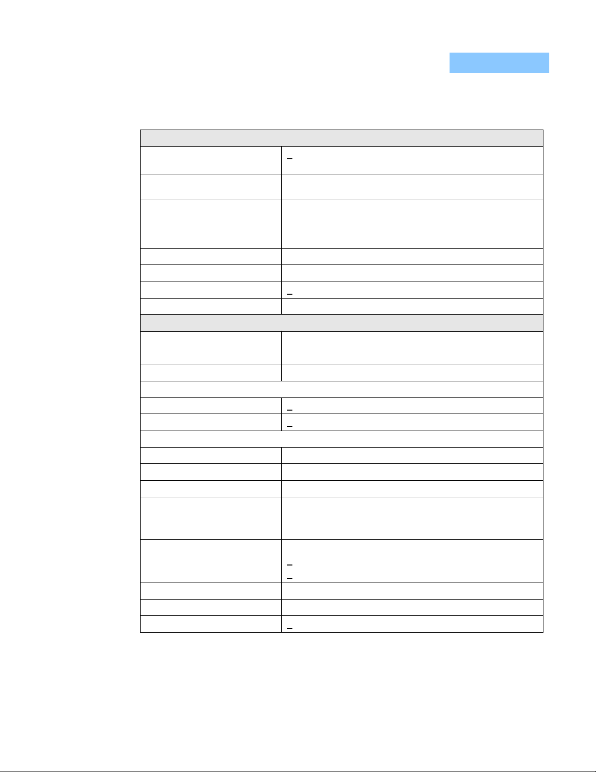
Specifications
INPUTS
Power Supply +
Control Output On (Default) when power supplied; user can control
Thermistor R Setting
External R
Internal R
Thermistor Current Jumper selectable 10 µA / 100 µA
Limit Jumper selectable: 250 mA, 500 mA, 1A, 1.5A, 2A
I
TE
Limit Accuracy +
TEC Gain 1 to 50; adjustable 1-turn pot
OUTPUTS
Output Type Bipolar, floating, constant current source
Current Range -2A to 2A
Compliance Voltage > 2 VDC
Stability (24 hours)
Internal R
External R
Temperature Coefficient
Internal R
External R
Thermistor Measurement Buffered output voltage: -5V to +5V
Transfer Function
100 µA range
10 µA range
Accuracy
100 µA range
10 µA range
set
set
set
set
set
set
1
12 to 18 Volts at 75 mA
+ 4.5 to 7 Volts at 2 A
output on / off with TTL line (Low = output off)
4
Jumper selectable internal/external R
Thermistor R driven to match reference precision resistor across
connector pins 5, 6
50 kΩ adjustable 10 T pot
50 mA
5
+ 0.01 oC
+0.005 oC
0.01 oC / oC (ambient)
0.005 oC / oC (ambient)
10 kΩ / V
100 kΩ / V
+
50 Ω
+
500 Ω
2
3
set
I
Measurement Buffered output voltage: -5V to +5V
TE
Transfer Function
Accuracy
05_07 LDT-5100 3
400 mA / V
40 mA
+
Page 14
CHAPTER 1
INTRODUCTION
Specifications
1
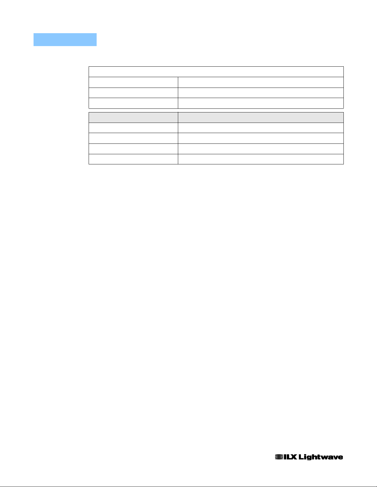
LED Indicators
Output On
TEC Open Error
Sensor Open Error
PCB pads for external LED (10 mA) and open collector output
PCB pads for external LED (10 mA) and open collector output
PCB pads for external LED (10 mA) and open collector output
6
6
6
GENERAL LDT-5100
Size 1.75” x 3.75” x 5.5” (44mm x 95mm x 139mm)
Weight 8.75 oz
o
Operating Temperature 0 to 50
Storage Temperature -40 to 70
1. All values tested after a one hour warm up period.
2. Additional current is needed if external LED indicators are used (approximately 10 mA per LED)
3. Higher voltage allowed with use of additional heat-sinking of mounting plate.
4. Use of an external precision resistor is the recommended method to set desired thermistor R.
5. Over any 24 hour period, controlling an LDM-4412 mount at 25
6. Open collector outputs for TEC open error , sensor ope n error and output on indicator can be used to co ntrol oth er functio ns such
as laser output disable line on the LDX-3100 current source.
C
o
C
o
C with a 10 kΩ thermistor on 100 µA setting.
4 LDT-5100
Page 15

CHAPTER 2
OPERATION
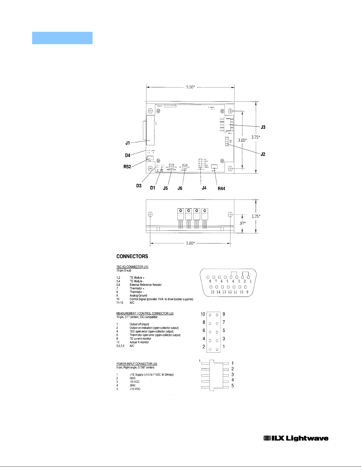
See Figure 2.1 for location and identification of control connectors and jumpers.
Thermistor Resistance Set Point
Two methods of thermistor R set point control are provided in the LDT-5100;
internal resistor or external resistor. A jumper, “RESISTOR SEL”, (J6) is used to
select which resistor is used as the set point reference for the control loop. (A
jumper on the left and center pins selects external resistor. Right and center pins
select internal resistor).
Note: A jumper must be present in one of the positions for the control loop to function.
Internal
In this mode, a 50 kΩ on board trim pot, “R SET” (R52) is used to set the control
resistance. Adjustment of this pot will cause the control loop to adjust the load
temperature so that the sensor thermistor value equals the trim pot resistance.
Although this will work in either thermistor current setting, improved accuracy will
result if the 100 µA range is used.
External
In this mode, the loop will use the resistance between pins 5 and 6 of the “TEC
I/O” connector (J1) as the set point. A fixed resistor should be used to achieve the
best load temperature stability. A variable resistor can also be used if fine
adjustment is required. The resistor value used will depend on the thermistor
sensor chosen and the current source range selected.
LDT-5100 5
Page 16
CHAPTER 2
OPERATION
6 LDT-5100
Figure 2.1 LDT-5100 Control/Monitor Connections
Page 17

OPERATION
Thermistor Current Source
Thermistor Current Source
For a greater range of temperature sensing, two current sources are provided on
the LDT-5100; 100 µA and 10 µA. Each source is selectable on the
“THERMISTOR CURRENT” jumper (J5). The default setting from the factory is
100µA.
Note: If the jumper is removed, the 100 µA current source (default) is selected. The choice
of current source will depend on the thermistor sensor used. Please refer to LX Lightwave
Application Note #2, Selecting and Using Thermistors for Temperature Con tro l.
Current Limit (J4)
The current limit selector (J4) allows the user to set the upper limit of the TE drive
current. The TE current limit is jumper selectable to five (5) values, 250mA,
500mA, 1A, 1.5A and 2A. The default limit is set to the minimum limit current of
250mA. The limit is for both positive and negative load currents. The limit current
value is selected by placement of a jumper at the indicated position on the
“CURRENT LIMIT” connector (J4). A jumper must be used in one of the five
positions in order for the LDT-5100 to function.
CHAPTER 2
TEC Gain
The proportional term of the LDT-5100 control loop can be adjusted with the “TEC
GAIN” trim pot (R44). When adjusted fully clockwise, the TEC GAIN is in the MAX
position. This corresponds to a proportional term gain of 50. With the TEC GAIN
adjusted fully counter-clockwise, the proportional term gain will be 1.
Measurement/Control (J2)
Output Off
An output off control line is provided at pin 1 of the measurement / control
connector (J2). When no connection is made, this line is internally pulled high and
the output is turned on (current is provided to the TE output). This is also the
condition at power-up. If the control line is grounded, the output will be off (no
current provided to the TE output). The control line input is a MOSFET allowing a
large variation in “low” voltage levels.
05_07 LDT-5100 7
Page 18

CHAPTER 2
Output Monitors
OPERATION
Measurement/Control (J2)
The LDT-5100 has two buffered output monitors present on the measurement /
control connector (J2). These monitor the actual thermistor resistance and I
(TE drive current).
TE
Thermistor Monitor
The thermistor monitor (pin 10) provides an output voltage wh ich is proportional to
the thermistor sense resistor value. The transfer function with the 100µA
thermistor current range selected is 10kΩ/V and with the 10µA thermistor current
range selected,100kΩ/V. The accuracy is specified to 5V although higher output
voltages can be measured.
TE Drive Current Monitor
A TE drive current monitor, ITE, is also provided as a buffered output on pin 8 of
the measurement / control connector (J2). This voltage output is proportional to
I
with a 400mA/V transfer function.
TE
Note: This is a bipolar output.
Status Monitors
The LDT-5100 measurement / control connector (J2) includes three status lines
which provide information about the instrument operation. They are thermistor
open, TEC open and output on. All outputs are open collector, allowing for a wide
variety of logic compatibility, including wired “or” operation. A pull-up resistor from
the user’s power supply is required. This power supply must also be connected to
the LDT-510 0 gro und reference for proper operation. Sink current in excess of 25
mA should be avoided when choosing the value of the pull-up resistor.
Thermistor Open (pin 6)
This control line is grounded (low) when the thermistor input, pins 7 and 8 of J1,
have a high impedance. The threshold for determination of high impedance is
dependent on the thermistor current range selected. The thresholds are 90 kΩ
and 900 kΩ for the 100 µA and 10 µA thermistor current ranges respectively.
When the sensor resistance is within the ranges indicated, the control line will be
high impedance, indicating an open thermistor.
TEC Open (pin 4)
This control line is grounded (low) when the TE module (+) and (-) inputs have a
high impedance. If the LDT-5100 tries to drive current to the TE, but is unable to
do so, an open TEC is assumed. Because of variation in TE load impedance and
8 LDT-5100
Page 19

OPERATION
LED Indicators
supply voltage, this threshold is not a fixed value. Under normal operation (with a
low impedance TE), the control line will be in a high impedance state.
Output On/Off (pin 2)
This control line indicates if the TE output is on (driving current to a TE load). A
ground at this control line indicates that the output is off and no current is being
driven through the TE modules.
LED Indicators
Pads are located on the LDT-5100 PCB to allow direct connection of indicator
LEDs. The indicator LEDs correspond to the three status lines described above.
These pads are internally referenced and do not require an external supply
connection. The ANODE pin of all three LEDs are connected so that a single
common wire can be used for remote LED indicators. The error LED indicators
(TEC Open (D3) and Thermistor Open (D1) are illuminated when an error is
sensed. The OUTPUT ON indicator (D4) is illuminated when the output is on.
CHAPTER 2
Note: If LEDs are used, the current requirement for the -15V supply should be increased
accordingly.
TEC I/O Connector (J1)
The 15-pin D-sub I/O connector pinout is shown in Figure 2.1. Simply connect
your TE module to the proper pins (observing the polarity of the TE) and connect
the thermistor sensor to complete the loop. The function of the external reference
resistor (pins 5 and 6) is described above under “Thermistor Resistance Set
Point”. A control signal at pin 10 provides a 1 V/A signal which can be used to
drive booster current supplies.
DC Power-In Connector (J3)
Separate ground leads are provided for the high current TE supply return and
control circuit ground reference. These pins (2 and 4) are connected on the
LDT-5100 PCB. To eliminate ground fluctuations caused by large TE current draw,
the TE return should be connected to the control supply only at the LDT-5100
PCB.
05_07 LDT-5100 9
Page 20

CHAPTER 2
OPERATION
DC Power-In Connector (J3)
10 LDT-5100
Page 21

CHAPTER 3
CALIBRATION
Thermistor Current Source Calibration
To calibrate the thermistor current source, connect an ammeter in series with a 10
kΩ resistor at the output connector (J1).
1 Place the thermistor current jumper (J5) in the 100 µA position.
2 Adjust trim pot R51 to read 100.00 µA on the current meter.
3 Place the thermistor current jumper (J5) in the 10 µA position.
4 Adjust trim pot R50 to read 10.00 µA on the current meter.
TE Current Limit Calibration
To calibrate the ITE limit current, connect a fixed known load
(approximately 1.0 Ω / 25 Watt) at the TE output.
1 Set the current limit jumper to the 1 Amp position.
2 Set the resistor select jumper in the internal position.
3 Adjust trim pot R52 so that a negative ITE current is produced.
4 Measure the voltage developed across the load with a voltmeter.
5 Adjust trim pot R5 so that the output current is 1.00 Amps.
LDT-5100 9
Page 22

CHAPTER 3
CALIBRATION
TE Current Limit Calibration
10 LDT-5100
 Loading...