

Page 1
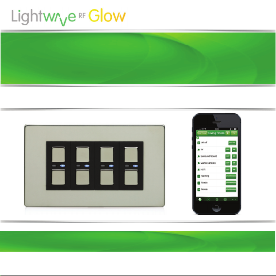
Dimmer Switch (4 Gang)
Model No. LW440
Instruction Manual
Connect Series
www.lightwaverf.house
Version 2.1
Page 2

EC DECLARATION OF CONFORMITY
Responsible Authority:
LightwaveRF PLC,
Innovation Campus Birmingham
Faraday Wharf
Holt Street
Birmingham
B7 4BB
Tel: +44 (0)121 250 3625
Email: enquiries@lightwaverf.com
Model Number(s): JSJSLW440
Description: 4 Gang Dimmer Switch
Directives this equipment
Complies with: 2006/95/EC The Low Voltage Directive N/A
2004/108/EEC The Electromagnetic Compatibility Directive
1999/5/EC R&TTE Directive
93/68/EEC CE Marking Directive
Standards Applied in order to verify compliance
Safety: BS EN 60730-1: 2011
Health:
R&TTE: EN 301 489-1 V1.9.2: (2011-09), EN 301 489-3 V1.4.1: (2002-08)
EN 300 220-1 V2.1.1: 2006, EN 300 220-2 V2.1.2: 2007
EMC: EN 301 489-1 V1.9.2: (2011-09), EN 301 489-3 V1.4.1: (2002-08),
EN 55022: 2010, EN 61000-3-2: 2006 +A1: 2009 +A2: 2009 Class A,
EN 61000-3-3: 2008, EN61000-4-2: 2009,
EN 61000-4-3: 2006 +A1: 2008 +A2: 2010, EN 61000-4-4: 2012,
EN 61000-4-5: 2006, EN 61000-4-6: 2009, EN 61000-4-11: 2004
For and on behalf of LightwaveRF PLC
---------------------------------------Name J Shermer
Position Managing Director
Page 3
Get Started
How do I get started?
Please refer to the following installation and
setup instructions. This will guide you, step by
step, through the installation and setup process.
What do I need?
To install the dimmer, you will need to remove
and replace the existing lightswitch. This is
usually straightforward, but you must ensure that
there is a suitably deep housing (backbox) and
understand how to safely turn o the electricity
supply. You will also need suitable electrical
screwdrivers.
Help video & further guidance
For additional guidance, and to watch a video
that will help guide you through the installation
process, please visit the support section on
www.lightwaverf.com
Page 4
Installation
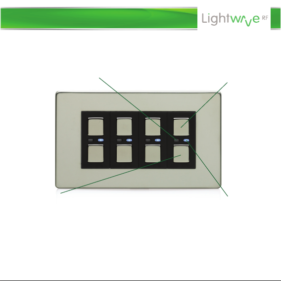
Overview
Amber LED. When illuminated,
the dimmer is o.
‘O’ button.
Hold to decrease light level.
IMPORTANT: All LightwaveRF products can be legally DIY installed in your
own home; however, if in doubt, always consult a qualified electrician or
heating engineer. It is important to install this product in accordance with
the following instructions. Failure to do so may void your warranty.
Blue LED. When illuminated,
‘On’ button.
Hold to raise light level.
the dimmer is on.
Page 5
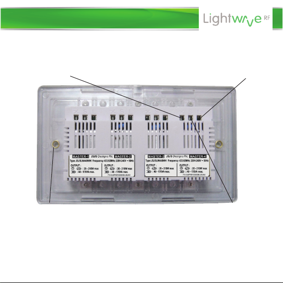
Installation
Switched live
(live out)
Screw mounting
hole
IMPORTANT: If conducting an insulation resistance test, all LightwaveRF
products must be disconnected from the mains, or damage will occur.
2-Way switching
Live in
connection
Page 6
Installation
1. IMPORTANT: Turn o the mains electrical supply.
2. Ensure that the wall (back) box has a minimum depth of 35mm.
3. Remove and disconnect the existing lightswitch (if applicable). It may be
useful at this point to mark out or take a photograph of the connections to
the existing switch so that the correct wires can easily be transferred to the
new dimmer. Some existing wiring configurations can be complex so take
care.
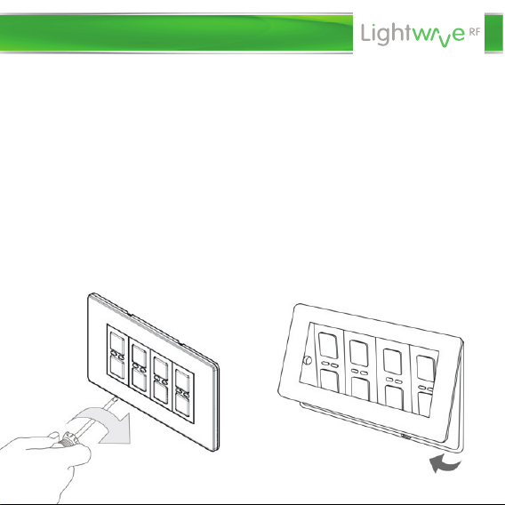
4. Gently remove the dimmer faceplate by inserting a screwdriver into one
of the bottom slots and lifting away from the unit as shown.
Page 7
Installation
5. Connect the wiring as per the wiring diagram on the following page.
Ensure that the terminals are properly tightened and that no bare wire is
visible. Be aware that existing wiring circuits are not always correctly
coloured, and that there may be other wired connections present in the back
box; if in doubt, always seek the advice of a qualified electrician.
NOTE: LightwaveRF dimmers do NOT require a mains neutral wire to be
connected; they only require ‘live in’ and ‘switched live out’.
6. Any earth wires present must be attached either to the earth terminal
located in the back box or capped with a strip connector. The dimmers are
double insulated so are not required to be earthed directly.
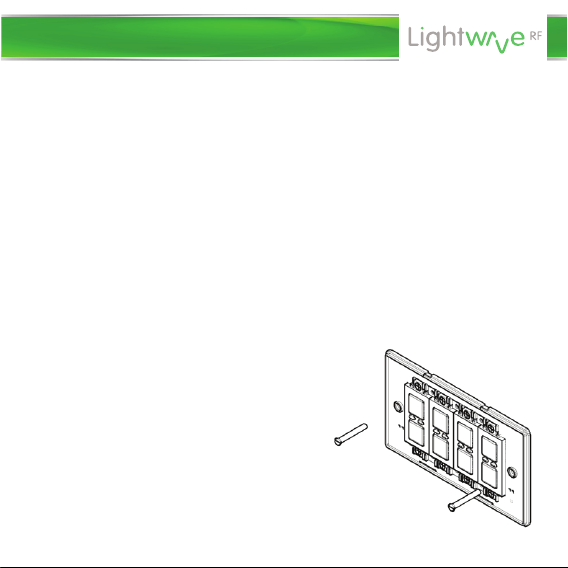
7. Screw the dimmer switch to the
mounting box and ensure that the
screws are suciently tight to support
the product, but do not over tighten as
this may cause the chassis to bend.
Ensure that the plastic spacer is
correctly aligned and that no wires are
trapped between the dimmer switch and
the back box.
Page 8
Installation
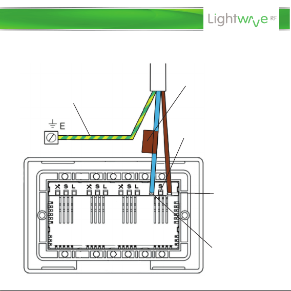
NOTE: Wiring shown for one of four
gangs. Please repeat for other gangs.
Earth wire connects to terminal in
back box (can be capped o
instead if no terminal present)
The switched live may be
marked by brown/red tape
to emphasise that it is not
a neutral wire.
Signal cable connection for
use with LightwaveRF
2-Way Dimmer only
(LOW VOLTAGE: Do not
connect to live mains!)
Live wire In. This
should be brown
or red in colour.
Switched live wire
out. This should
be blue or black in
colour.
Page 9
Installation
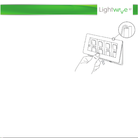
8. Replace the plate – a ‘click’ sound
should be heard to signify that the
plate has been correctly replaced.
Important things to consider
• In a multigang dimmer, to be able to
operate any gang, mains electricity
must always be connected to all of the
dimmer terminals.
• It is recommended that LightwaveRF devices be positioned at least 30cm
apart in order to prevent the risk of any radio conflict that could disrupt
remote operation.
• Suitable lamps must be used with the dimmer or it will not function
correctly. See next section for compatibility information.
Page 10

Installation
Connecting to a 2-Way Dimmer
• Any LightwaveRF dimmer switch (and any gang in a multigang dimmer)
can be used in conjunction with a LightwaveRF 2-way dimmer to perform
2-way switching. For full instructions on how to install a 2-way dimmer,
please consult the instruction booklet for the 2-way dimmer.
Important: The dimmer must be used with a LightwaveRF 2-way dimmer
and cannot be used with another LightwaveRF dimmer or a standard light
switch. This will cause damage to the dimmer.
• Up to six 2-way dimmers (six gangs) can be connected to a standard
LightwaveRF dimmer switch. Each 2-way can be connected directly to the
standard dimmer, or connected to each other in a ‘daisy-chain’. This
provides an alternative to using intermediate switches (maximum cable
length of 100m)
• The 2-way dimmers use standard 3-core connecting wires; however,
because they are electronic dimmers, they utilise one of the cores as a
signal cable (‘S’) running between the dimmers (as shown on the diagram).
This is low voltage only and should not be connected to 230V mains.
Important: Never install and run power to a LightwaveRF 2-way dimmer
switch before first installing and connecting the counterpart standard
LightwaveRF dimmer. Serious damage could be caused to the unit.
Page 11

Installation
From Lighting Circuit
Switched Live
Earth
Live
3-Core
Cable
Switched Live
IMPORTANT: The signal cable input
marked ‘S’ must ONLY be connected
to the wire running to the other
dimmer NOT live mains; this will
cause irreparable damage.
Live
Signal Cable
Page 12

Compatibility & Lamps
Compatibility
Ensuring the compatibility of your lamps (bulbs) with LightwaveRF Dimmers
will ensure that you get the best experience from your lighting setup.
LightwaveRF dimmers are compatible with the following:
• Selected dimmable LED lamps (see www.lightwaverf.house for further
guidance and information).
• Standard mains voltage incandescent & low energy incandescent lighting
(min 20W, max 250W)
• GU10 and equivalent HI spot mains halogen lamps
• Dimmable electronic low voltage transformers (20W - 250W max.)
• Inductive transformers (40 – 170VA max.)
LightwaveRF dimmers are NOT compatible with the following:
• Wirewound transformers (generally older style)
• Electric motors
• Non dimmable LEDs
• CFLs
• CFL tube arrays
Page 13

Compatibility & Lamps
Adjusting the dimming range
On initial setup, LightwaveRF Dimmers are pre-programmed to allow a
moderate range of dimming for any connected lamps. If desired, this range
can be extended by following the instructions below.
The reason for allowing modifications to the dimming range is to maximise
compatibility with dimmable LED lamps (bulbs). In some cases, LED lamps
may flicker slightly at high or low brightness levels, especially if there is only
a modest overall circuit load (under 10W). Stability can be achieved by a
very slight adjustment to the dimming range of the LightwaveRF Dimmer.
The default setting (smallest dimming range) is the most stable for LEDs. If
the LEDs perform normally at this setting (most cases), then the range can
be increased (if desired) using the following method.
1. On the dimmer switch, press and hold
down both the ‘on’ and ‘o’ buttons until
the blue and amber LEDs flash alternately
then release them. The dimmer switch is
now in linking mode.
Page 14

Installation
Compatibility & Lamps
Compatibility & Lamps
2. Tap the (top) ‘on’ button twice to enter
Dimming Range Setup. The blue LED will flash
to indicate that the setup menu has been
accessed. The dimmer will automatically
on at a high level of brightness. This
turn
indicates
dimming
Dimming Range Setup allows the dimmer’s range to be adjusted to one of
five presets. If the dimmable LED lamps on the circuit perform properly at
the initial setting (smallest range), then the range can be increased, one
stage at a time, until flickering (if any) is observed. The optimum setting is
the one which provides the greatest dimming range without any flicker.
that the smallest (most stable)
range is currently selected.
3. Tap the ‘o’ button to gradually increase
the dimming range (indicated by the
incremental decrease in lamp light level).
Keep going until flicker is observed. At this
point, return to the previous stable increment
(optimum level) by pressing the ‘on’ button.
4. Once the optimum level has been achieved, save the setting and leave
setup by holding the on & o buttons until the blue LED flashes quickly.
Page 15

Compatibility & Lamps
Compatibility & Lamps
Important things to consider
• Wattage ratings for the dimmers are per gang. This means that a total
of 250W (incandescent) can be put on each circuit connected to each
• LightwaveRF Dimmers utilise a tiny amount of power to drive the
electronics that operate the RF radio and dimming components. As a result,
it is normal to experience a 5-10% reduction in light output when using
incandescent lamps (bulbs). In the vast majority of cases, this should not be
noticeable as the drop is very small.
• ONLY dimmable lamps can be used even if the dimmers are used solely to
switch between the on and o states without dimming. This is because the
technology used in an electronic dimmer is fundamentally dierent to that
of a simple on/o switch and requires compatible lamp technology.
• Electronic transformers can be used only if they are dimmable. Please
check carefully that the loading and lamp compatibility is appropriate.
load
gang.
Page 16

Manual operation
Manual operation
Manual dimming
• Tap the ‘on’ (top) button once to
switch the dimmer on (blue LED
indicator will illuminate). Press and
hold the ‘on’ button to raise the light
level.
• Tap the ‘o’ (bottom) button once
to switch the dimmer o (amber LED
indicator will illuminate). Press and
hold to lower the light level.
NOTE: When the ‘on’ button is tapped to turn on the dimmer, the light level
will return to that at which it was last at before the dimmer was turned o.
The ‘on’ or ‘o’ buttons can then be pressed and held to customise the light
level.
Page 17

Device setup
Linking the dimmers to the App or a remote
NOTE: This procedure also applies to other LightwaveRF controllers (e.g.
Handheld Remote or Mood Controller) which can be linked to the dimmers.
LightwaveRF dimmers each have 6 unique memory slots which means they
can link with up to 6 LightwaveRF controllers in total. If you are using a
smartphone/tablet/PC to control the dimmer via the Lightwave Link, this
will always count as ONE controller and take up one memory slot even if you
are using multiple smartphones/tablets.
1. On the dimmer switch, press and hold
down both the ‘on’ and ‘o’ buttons on one
of the gangs until the blue and amber LEDs
flash alternately then release them. The
dimmer switch is now in linking mode.
2. Using the LightwaveRF App, press the
‘connect’ button (the App instructions will
guide you through this). If using another
controller, press the button that you intend to
link. The blue light on the dimmer switch will
flash to confirm that the App is now linked.
Page 18

Device setup
NOTE: Linking mode lasts for 12 seconds; if no signal is received from a
remote handset during this time then the dimmer will automatically exit
learning mode without linking the device.
If, when expecting a blue LED flash to confirm pairing, a slow amber LED
flash is received instead, the dimmer switch memory is FULL and no further
remotes may be linked with it unless one of the existing remotes is first
unpaired (see below).
Unlinking controllers
Removing a single device:
1. On the dimmer switch, press and hold down
both the ‘o’ and ‘on’ buttons until the blue and
amber LEDs flash alternately then release them.
The dimmer switch is now in linking mode.
2. Using the LightwaveRF Smartphone App,
enter the edit menu and press the delete button
next to the relevant device (the App instructions
will guide you through this). If using another
controller press the button that you intend to
unlink. The amber light on the dimmer switch will
flash to confirm that the App is now unlinked.
Page 19

Device setup
Clearing the memory (will remove all linked controllers):
1. Press and hold down both the ‘on’ and
‘o’ buttons on one of the gangs until
the blue and amber LEDs flash
alternately then release. The dimmer
switch is now in linking mode.
2. On the dimmer switch, press and hold
down the ‘o’ button again until the
blue and amber LEDs flash
simultaneously, then tap (don’t hold)
the ‘o’ button a further time; the amber
LED will flash to confirm that the
NOTE: Reliable range of remote operation is around 15 metres indoors and
up to 100m outdoors (using a Lightwave Link). This figure may vary
depending upon the environment; very thick walls, bodies of water or large
metal objects may interfere with radio range.
If the distance between the transmitter and receiver is too great to achieve
reliable operation, the LightwaveRF Signal Booster may be used in
conjunction with this product to increase the range.
Page 20

Remote operation
Remote operation
Dimming with the LightwaveRF
App or a LightwaveRF controller
• Press the ‘on’ button on the App (or other
LightwaveRF controller) once to switch the
dimmer on (blue LED indicator will
illuminate). Use the slider to raise or lower
the light level (or press and hold the on or
o button on any other LightwaveRF
controller).
• Press the ‘o’ button on the App (or other
LightwaveRF controller) once to switch the
dimmer o (amber LED indicator will
illuminate).
Page 21

Remote operation
Locking the Dimmer Switch
• The dimmer can be ‘locked’ so that the manual buttons will not operate it.
This can be achieved using the LightwaveRF App or a ‘Socket Locker’
remote. If it is locked on, then the dimmer will not turn o manually. If it is
locked o, it will be possible to turn the dimmer on, but it will automatically
turn o again after five minutes. A locked dimmer is signified by a slow
flashing amber LED.
• To lock/unlock the dimmer, press the ‘unlock’ button on the Smartphone
App or Socket Locker. If the Socket locker is misplaced, the dimmers can be
reset by turning of mains power to the circuit for a period of 30 seconds.
Understanding flashing LED sequences on the dimmer
Flashing blue & amber alternately: Socket in Linking Mode
Quickly flashing blue: Socket successfully linked
Quickly flashing amber: Socket unlinked / memory cleared
Slowly flashing amber: Socket memory full / socket locked
Blue & flashing amber: Socket successfully locked / unlocked
Page 22

Creative ideas
1. (Easy): Family safety
Products Required: Dimmer Switch, PIR Motion Sensor
Here we have a LightwaveRF Dimmer Switch paired to a PIR Motion Sensor.
When somebody is detected by the sensor, it triggers the dimmer
automatically and turns the light on. So, when one of the kids needs to use
the bathroom in the middle of the night, the path is safely lit for them. The
light is then set to turn o once no movement has been detected for a
period of time. So, when the little one is safely back in bed, the sensor will
turn o that light that is always normally left on!
Page 23

Creative ideas
2. (Intermediate): Scene lighting
Required: Dimmer(s), Mood Controller, Plug-ins
Dimmer Switches & Dimmable Plug-ins enable you to control all of your
lounge ceiling lights and socket powered lamps individually or together as a
group. The Mood Controller allows you to set and recall your own favourite
lighting scenes at the touch of a button. You can dim all the lights for watching
a movie or create a relaxed mood for entertaining guests. At the end of the
evening, press the ‘all o’ button to turn o all lights and lamps. Adding the
Lightwave Link allows scene lighting to be controlled via a smartphone.
Page 24

Creative ideas
3. (Advanced): Simulated occupancy
Required: Dimmer(s), Power Sockets or Plugins, Link
This setup gives you control over your devices from anywhere in the world.
Here we have ceiling lights controlled by dimmers and lamps plugged into
Lightwave Power Sockets or Plug-in Sockets. Via the Lightwave Link, every
light can be controlled using a smartphone wherever you are. So, when
you’re away on holiday, you can turn on lights to make it look like someone’s
home. You can even set them to come on automatically at dierent times
each evening - enough to fool even the most watchful of intruders!
Page 25

Troubleshooting
Problem: The dimmer will not operate the light and the LEDs on the
dimmer do not light up.
Solution: First, check that there is power to the dimmer. Make sure that the
connected lamps are functioning correctly; the dimmer switch will not run
unless it has a functioning lamp(s) to complete the circuit. Ensure that the
maximum LED/incandescent loading has not been exceeded (if so this may
have damaged the dimmer). Check that the wiring is correct; it is important
that the live and switch live wires are attached to the correct terminals - a
common mistake is to reverse these connections. If these measures fail,
contact technical support via www.lightwaverf.com.
Problem: The switch is powered (amber or blue LEDs on), but it will not
link to a LightwaveRF handset or controller.
Solution: Check the controller battery strength: if the battery strength is
low, it will not produce enough power to drive the RF radio signal. Tap any
‘on’ button on the controller to transmit a signal. A strong battery signal is
indicated by the LED light on the controller remaining lit for 1-2 seconds after
releasing the button. A low battery is indicated if the LED light turns o
immediately. If this happens, please replace the battery.
Page 26

Troubleshooting
Problem: The LED/CFL lamps that I am using flash / do not dim properly.
Solution: Ensure that the lamps being used are dimmable; non dimmable
lamps are not compatible with LightwaveRF Dimmers. If the lamps are
dimmable yet the problem persists, the LED/CFL lamps may not be
compatible with the dimmers. Please contact technical help (via
www.lightwaverf.house) for further advice.
Problem: The dimmer will not consistently operate remotely.
Solution: The controller/Lightwave Link may be encountering interference
or may be at the edge of its reliable range of operation. Ensure that there are
no thick walls, large pieces of metal or bodies of water in the path of the
transmission. If the problem persists, try moving the controller/Link closer to
the dimmer, or consider using a LightwaveRF Signal Booster to extend the
range by relaying the signal between controller and dimmer.
Problem: The dimmer keeps turning o automatically/wont turn o and
displays flashing amber & blue lights.
Solution: The dimmer is locked. This may have been done using a Socket
Locker or from the LightwaveRF App. If it is locked on, then the dimmer will
not turn o manually. If it is locked o, it will be possible to turn the dimmer
on, but it will automatically turn o again after five minutes. To unlock the
dimmer, press the unlock button on the Socket Locker or Smartphone App.
If this is not possible, the dimmers can be reset by turning o mains power
to the circuit for a period of 30 seconds.
Page 27

FAQs
Q. Does the dimmer have a ‘standby’ power consumption?
A. The dimmer has a standby power consumption of approx. 0.5W. This is
because the in-built radio receiver requires power in order to receive
commands. This rate is low and well within government energy guidelines.
Q. How do I know that the dimmer switch will fit?
A. The dimmer is the same size as a standard lightswitch - it will fit all back
boxes (standard lightswitch housing) over 35mm deep.
Q. Is it legal for me to to install the dimmer?
A. Yes, it is fully legal to install LightwaveRF in your own home.
Q. Is there a maximum number of bulbs I can control with the dimmer?
A. You can control any number of bulbs as long as they do not exceed the
maximum loading in total. Note: Max. load diers for LED/incandescent.
Q. How many devices can I have on the LightwaveRF system?
A. Each device has 6 memory slots for up 6 controllers (one of these can be
the Lightwave Link allowing up to 6 smartphones to control up to 240
devices.
Q. Can I use LED bulbs?
A. Yes as long as the bulbs are dimmable variants and compatible.
Page 28

FAQs
Q. Can I use non dimmable bulbs if I don't dim them?
A. No. The bulbs must be dimmable even if they are not dimmed; the
technology in the bulb must be compatible with that of the dimmer.
Q. What if I need a switch to operate on/o only?
A. A LightwaveRF Relay in conjunction with a Wire-free Switch can be used
for on/o switching in place of the dimmer (see www.lightwaverf.house).
Q. Can I separate and change individual switches in multigang dimmers?
A. Multigang dimmers are not designed to have their switch modules
separated and interchanged; disconnecting and removing dimmer modules
will invalidate the warranty.
Q. Can I expect a drop in light output with a LightwaveRF dimmer?
A. LightwaveRF dimmers utilise a tiny amount of power to drive the
electronics that operate the RF radio and dimming components. As a result, it
is normal to experience a 5-10% reduction in light output when using
incandescent bulbs. In the vast majority of cases, this should not be noticeable
to the naked eye.
Q. Is it normal for the dimmer to get warm when it is turned on?
A. Yes, it is perfectly normal for dimmer switches to feel warm to the touch if
left on for a period of time. It is completely safe.
Page 29

Technical Specification
Specification
RF frequency: 433.92 MHz
Input rating: 220-240V~ 50Hz.
Output rating: 3W~210W max (per gang)
Incandescent Load: 20W min 210W max (per gang)
Back Box Depth: 35mm min.
Earthing Requirement: Not essential (double insulated)
Standby Energy Use: Less than 1W (per gang)
Wiring: Neutral wire NOT required
Warranty: 2 year standard warranty
Page 30

2 Quadrant Park
Mundells
Welwyn Garden City
Herts
AL7 1FS
01707 386035
www.lightwaverf.house
Version 2.1
 Loading...