

Page 1

User’s Manual
®
®
.
P/N 60600028 Rev. A
High End Systems Inc.
2217 West Braker Lane
Austin, Texas U.S.A.
Page 2

© High End Systems, Inc. 1993-97, All Rights Reserv ed
Informati on and Specifications in this document are subject to change without notice. High End Syste ms , Inc.
assumes no respon sibility or liabi lity for any errors or inaccur acies that may appear in this manual . The software
described in this manual is furnished under a license agreement and may be used or copied onl y in accordance
with the terms of the agreement.
Unlawful reproduction or distribution in any manner without the written permission of High End Systems is strictly
forbidden.
High End Systems accepts no liability for computers tha t do not work with the
Since PC systems have BIOSs that are different from one com pany to another t here can be absolutely no guarantee that a particular machine will work perfectly for the use of a
Trademarks used in this text:
Intellab eam, Lightwave Research
Studio Color
Pin Scan, Stage Scan, Super Scan, Super Scan HPE, Super Scan Zoom, and Tiger Scan are tr adem arks of Clay
Paky ; Nat TM 1200, Nat TM 2500, Nat MM 1200, and Nat MM 2500 are trademarks of Coemar; MAC 600, MAC
1200, PAL 1200, Roboscan Pro400, Roboscan Pro518, and Roboscan Pro1220 are trademarks of Martin Professional; Stratos is a trademark of Studi o Due; AR5, VL5, VL5A, VL6, and VLM are trade ma rks of Vari -l ite Inc., MSDOS, Windows 95 and Windows are tra dem arks of Micr osoft Corporation; Littlite is a registered trademark of CAE
Inc.; Pentium is a regist ered trademark of Intel .
Other trademarks and trade names may be used in this software to refer to either the entities claiming the marks
and/or their products. High End Systems makes no claim of any proprietary interest in trademarks and trade
names other than its own.
Status Cue uses one or mor e of the f o llo wing pate nts: US 4,9 62,687; US 5,078,039; UK 2,043,7 69; US 5,331, 822;
US 5,402,326; UK 2292896; US D365165; US 5,430,629; US D360,404; US 5,455,748; 0475082; US 5,506,762;
M9604224.9; US 5,515, 254; US D370080; UK 2.291,814; US 5,545. 951; UK 2055842; UK 2,292,530; UK
2294909; UK 2292896; 1052/96; 862-1996; and US 5,580,164.
Other patents m ay be pending.
, and
Trackspot
Dataflash, Color Pro, Cyberlight
, the
Lightwave Research
are registered trademarks of Hi gh End Systems Inc.; Golden Scan 2, Golden Scan 3,
Status Cue
, the
High End Systems
logo,
Lithopatterns, Status Cue
Status Cue
system.
lighting console syst em.
logo,
High End Systems
, the
Status Cue
,
logo,
May 13, 1997
Status Cue User’s Manual
P/N 60600028 Rev. A
Status Cue 3-Ring Binder
P/N 90901002
Kit with Manual, Binder, and Inserts
P/N 80430047
Printed in the U.S.A.
.
Page 3

Declaration of Conformity
according to I SO /I EC Guide 22 and EN45104
Manufacturer: Lightwave Research
2209 West Braker Lane
Austin, Texas 78758
U.S.A.
Exclusive Distributor: High End Systems, Inc.
2209 West Braker Lane
Austin, Texas 78758
U.S.A.
declares that the product
Product Name: Status Cue Li ghting Console and LinkCard
Product Number: Status Cue
Product Options: All
conforms to the following Product Specifications:
Safety: EN 60950 : 1992
A1 : 1993
A2 : 1994
EMC: EN 55022 : 1987 Class A ITE
IEC 801-2 : 1991 Level 2 (4/8 kV)
IEC 801-3 : Draft 5 Level 2 (3V/m)
IEC 801-4 : 1988 Level 2 (0.5 kV / 1 kV)
Supplementary Information:
The products herewith comply with the require ments of the Low Voltage Directive 72/23 /EEC and the
EMC Directive 89/336/EEC.
The Status Cue Lighting Consoles were tested in a typical con f iguration with ISA bus LinkCards manu-
factured by Lightwave Research. The Status Cue Lighting Console s were tested in a typical configuration with Austin Com puter.
U.S.A., October 09, 1997 Lanny Derryberry, Compliance Engineer
Page 4

IMPORTANT SAFETY INFORMA TION
INSTRUCTIONS PERTAINING TO CONTINUED PROTECTION AGAINST FIRE, ELECTRIC
SHOCK, AND INJURY TO PERSONS ARE FOUND IN APPENDIX C.
READ ALL CAUTIONS AND WARNINGS PRIOR TO ASSEMBLY, MOUNTING, AND OPERATING THIS EQUIPMENT.
IMPORTANT: INFORMATIONS DE SÉCURITÉ
INSTRUCTIONS RELATIVES À UNE PROTECTION CONTINUE CONTRE L' INCENDIE, LE
CHOC ÉLECTRIQUE, ET CONTRE DES BLESSURES POSSIBLES SUR DES INDIVIDUS SE
TROUVENT DANS L'APPENDICE C.
PRIÈRE DE LIR E TOU TES LES PRÉCAUTI ON S ET LES AVERTISSEMENTS AVANT
D'ASSEMBLER, DE MONTER, ET DE FAIRE FONCTIONNER CET ÉQUIPEMENT.
WICHTIGE SICHERHEITSHINWE ISE
DIE NACHSTEHENDEN HINWEISE BETREFFEN DEN SCHUTZ GEGEN BRAND, ELEKTRISCHEN SCHLAG, SOWIE VERLETZUNGEN. SIE BEFINDEN SICH IN APPENDIX C.
LESEN SIE ALLE WARNUNGEN SORGFÄLTIG, BEVOR SIE DAS GERÄT ZUSAMMENBAUEN, INSTALLIEREN UND BENUTZEN!
INFORMACIÓN IMPORTANTE DE SEGURIDAD
SE ENCUENTRAN EN EL APÉNDICE C LAS INSTRUCCIONES CONCERNIENTES A LA PROTECCIÓN CONTINUA CONTRA INCENDI O, CHOQUE ELÉCTRICO, Y LESIONES A PERSONAS.
POR F AVOR LEA TODAS LAS PRECAUCIÓNS Y LAS ADVERTENCIAS ANTES DE ENSAMBLAR, MONTAR Y OPERAR ESTE EQUIPO.
INFORMAZIONI IMPORTANTI DI SICUREZZA
ISTRUZIONI PERTINENTI LA PROTEZIONE CONTRO IL FUOCO, LE SCOSSE ELETTRICHE, I
DANNI ALLE PERSONE SI TROVANO NEL APPENDICE C.
LEGGERE TUTTI GLI AVVERMENTI PRIMA DI MONTARE E USARE QUESTO APPAR ECCHIO.
FCC Statement
This equipment h as been tested and found to co mply with the limits f or a Class A digital device, pursuant to part 15 of the FCC rules. These lim its are des igned to provide reasonable protection agains t harmful interference when the equipment is operated in a commercial environment. This equipment
generates, use s, and can ra diate radio freque ncy ene r gy and, if not install ed and use d in accorda nce with
the instruction manual, may cause harmful interference to radio communications. Operation of this
equipment in a residential area is likely to cause harmfu l interfere nce in which case the user will be
required to correct the interference at hi s own expense.
Page 5

Warranty Inform at ion
Limited Warranty
Unless otherwise stated, your product is covered by a two year parts and labor limited warranty.
Dichroic filters and Lithopatterns ® a r e not guarant eed against breakage or s cratches to coating. It is the
owner's responsibility to furnish rec eipts or invoices for veri fication of purchase, date, and dealer or
distributor. If purchase date cannot be provided, da te of manu facture will be used to determine warranty
period.
Returning an Item Under Warranty for Repair
It is necessary to obt ain a Return Authorization Number (RA#) from your dealer/point of purchase
BEFORE any units are returned for repair. The manufacturer will make the final determination as to
whether or not the unit is covered by warranty. Lamps are covered b y the lamp manufacturer's warranty.
Any Product unit or parts returned to High End Systems mu st be packaged in a suitable manner to
ensure the protection of such Product unit or parts, and such package shall be clearly and prominently
marked to indicate that the package contains returned Prod uct units or parts and wit h a Return
Authorization (RA#) number. Accompany all returned Product units or parts with a written expl ana tion
of the alleged problem or malfunction.
Please note: Freight Damage Claims are invalid for fixtures shi pped in non-factory boxes and pac king
materials.
Freight
All shipping will be paid by the purchaser. Items under warranty shall have return shipping paid by the
manufacturer only in the Con tinental United Stat es . Under no circumstances will freight collect
shipments be accepted. Prepaid shipping does not include rush expediting such as airfreight. Airfreight
can be sen t cu stomer co llect in the Continental United States.
REPAIR OR REPLACEMENT AS PROVIDED FOR UNDER THIS WARRANTY IS THE
EXCLUSIVE REMEDY OF THE CONSUMER. HIGH END SYSTEMS, INC. MAKES NO
WARRANTIES, EXPRESSED OR IMPLIED, WITH RESPECT TO ANY PRODUCT , AND HIGH
END SPECIFICALLY DISCLAIMS ANY W ARRANTY OF MERCHANTABILITY OR FITNESS
FOR A P ARTICULAR PURPOSE. HIGH END SHALL NOT BE LIABLE FOR ANY INDIRECT,
INCIDENTAL, OR CONSEQUENTIAL DAMAGE, INCLUDING LOST PROFITS, SUSTAINED
OR INCURRED IN CONNECTION WITH ANY PRODUCT OR CAUSED BY PRODUCT
DEFECTS OR THE P ARTIAL OR TOTAL FAILURE OF ANY PRODUCT REGARDLESS OF THE
FORM OF ACTION, WHETHER IN CONTRACT, TORT, (INCLUDING NEGLIGENCE), STRICT
LIABILITY, OR OTHERWISE, AND WHETHER OR NOT SUCH DAMAGE WAS FORESEEN OR
UNFORESEEN.
Warranty is void if the product is misused, damaged, mod ified in any way, or for unauthorized re pairs
or parts. This warranty gives you specific legal rights, and you may also have other rights whic h vary
from state to sta t e.
Page 6

Software Pr ogram License Agreement
PLEASE REVIEW THE FOLLOWING TERMS AND CONDITIONS CAREFULLY BEFORE OPENING THIS
PACKAGE. BY OPENING THIS PACKAGE, YOU INDICATE YOUR ACCEPTANCE OF SUCH TERMS
AND CONDITIONS. IN THE EVENT THAT YOU DO NOT AGREE WITH ANY OF THEM, YOU SHOULD
PROMPTLY RETURN THE PACKAGE UNOPENED. YOUR MONEY WILL BE REFUNDED.
Pursuan t to this Agreement, you may: (a) use the program on a single comp uter; (b) copy of the program into
any computer readable or printed for m for ba ck-up or m odifications p u rposes in suppor t of your use of the p rogram
on the single computer (certai n programs, how ever , may inclu de m echanisms to limit or inhibit copying; they are
marked "copy protected"); (c) modify the program and merge it into another program for your use on the single
computer; and (d) transfer the program and license to another party if the other p arty agrees to accept the terms and
conditions of this agreement .
Any porti on of this program merged into another program will continue to be subject to the terms and conditions of the agreement. If you transfer the program, you must at the same ti me either transfer all copies whether in
printe d or computer readable form to the sa m e party or de stroy any co pies not transferred, incl uding all modifications and p ortions of the program contained or m erged in to other programs. You must also reproduce and include
the copyr ight noti ce on any copy, modification, or portion merge d into anoth er program.
YOU MA Y NOT USE, COPY, MODIFY, OR TRANSFER THE PROGRAM, OR ANY COPY, MODIFICATION, OR MERGED PORTION, IN WHOLE OR IN PART, EXCEPT AS EXPRESSLY PROVIDED FOR IN
THIS AGREEMENT. IF YOU TRANSFER POSSESSION OF ANY COPY, MODIFICATION, OR MERGED
PORT ION OF THE PROGRAM TO ANOTHER PARTY, YOUR LICENSE I S AUTOMATICALLY TERMINATED.
Term
The license is effective until terminated. You may terminate it at any other time by destroying the program,
togethe r w ith all copies, modi fications, and mer g ed portions in any for m . It will also terminate upon conditions set
forth e lsewhere in this Agreement or if you fa il to comply with any term or condit ion of this Agreement. You agree
upon such termination to destroy the program together with all copies, modifications, and merged portions in any
form.
Limited Warranty and Remedies
HIGH END SYSTEMS, IN C. warran ts the diskette(s) on wh ich the program is furnished, to be free from
defect s in mater ia ls and workm an ship und er norma l use for a per io d of one (1) year from the dat e of de li very t o you
as evidenced by a copy of your receipt. This warranty is limited to you and is not transferable.
During the 1 year warranty period, HIGH END SYSTEMS will (1) repl ace any disk ette not meeting the fo regoing warranty and which is returned to HIGH END SYSTEMS or Authorized HIGH END SYSTEMS Dealer
(“Authorized Dealer”) with a copy of your receipt; or (2) if HIGH END SYSTEMS or the Authorized Dealer is
unable t o deliver a replac em ent disk ette tha t is free of defects in materials or workmanship, you may terminate this
Agreement by returning the program and your money will be ref unded.
Page 7

THE FOREGOING WARRANTY DOES NOT EXTEND TO ANY DISKETTE THAT HAS BEEN DAMAGED AS A RESUL T OF ACCIDENT, MISUSE, ABUSE, OR AS A RESULT OF SERVICE OR MODIFICATION BY ANYONE OTHER THAN HIGH END SYSTEMS OR AN AUTHORIZED DEALER. EXCEPT AS
EXPRESSLY SET FORTH ABOVE, NO OTHER WARRANTIES, EITHER EXPRESS OR IMPLIED, ARE
MADE WITH RESPECT TO THIS PROGRAM, INCLUDING, BUT NOT LIMITED TO THE IMPLIED WARRANTIES OF MERCHANTABILITY AND FITNESS FOR A PARTICULAR PURPOSE, AND HIGH END
SYSTEMS EXPRESSLY DISCLAIMS ALL WARRANTIES NOT STATED HEREIN. YOU ASSUME THE
ENTIRE RISK AS TO THE QUALITY AND PERFORMANCE OF THE PROGRAM. SHOULD THE PROGRAM PROVE DEFECTIVE, YOU-AND NOT HIGH END SYSTEMS-OR AN AUTHORIZED DEALERASSUME THE ENTIRE COST OF NECESSARY SERVICING, REPAIR, OR CORRECTION. SOME JURISDICTIONS DO NOT ALLOW THE EXCLUSION OF IMPLIED WARRANTIES, SO THE ABOVE EXCLUSION MAY NOT APPLY TO YOU. THIS WARRANTY GIVES YOU SPECIFIC LEGAL RIGHTS, AND YOU
MA Y ALSO HAVE OTHER RIGHTS WHICH VARY FROM JURISDICTION TO JURISDICTION.
HIGH END SYSTEMS does not warrant that the functions contained in the program will mee t your requirements or that the operation of the progra m wi ll be uninterrupte d or error-free. You also assume responsi bility for
the se lection of the program to achieve your intended res u lts, and for the in stallation, use, and results obtained fro m
the program .
YOUR SOLE REMEDIES AND HIGH END SYSTEMS ENTIRE LIABILITY ARE AS SET FORTH
ABOVE. IN NO EVENT WILL HIGH END SYSTEMS BE LIABLE TO YOU OR ANY OTHER PERSON FOR
ANY DAMAGES, INCLUDING ANY INCIDENT AL, OR CONSEQUENTI AL DAMAGES, EXPENSES, LOST
PROFITS, LOST SAVINGS, OR OTHER DAMAGES ARISING OUT OF THE USE OF OR INABILITY TO
USE SUCH PROGRAM.
SOME JURISDICTIONS DO NOT ALLOW THE LIMITATION OR EXCLUSION OF INCIDENT AL OR
CONSEQUENTIAL DAMAGES FOR CONSUMER PRODUCTS, SO THE ABOVE LIMITATIONS OR
EXCLUSIONS MAY NOT APPLY TO YOU.
General: Sublicenses, Assignm ents, Transfers
You may not sublicense, assign, or transfer the license or the progra m ex cept as exp ressly provided in this
Agreemen t. Any att em pt to oth e rwise sub license , assign, or transfer any of the right s, duties, or obligations hereunder is nul l and void.
This Agreement is governed by the Laws of the State of Texas and the United States of America except for
their c onflicts of law provisions. Venue of any disput e hereunder shall reside in the courts of T ravis Coun ty, Texas,
U.S.A.
Governing Law
This Agreement is governed by th e Law s of the State of Texas, USA.
YOU ACKNOWLEDGE THAT YOU HAVE READ THIS AGREEMENT, UNDERSTAND IT, AND
AGREE TO BE BOUND BY ITS TERMS AND CONDITIONS; YOU FURTHER AGREE THAT IT IS THE
COMPLETE AND EXCLUSIVE ST ATEMENT OF THE AGREEMENT BETWEEN US WHICH SUPERSEDES ANY PROPOSAL OR PRIOR AGREEMENT, ORAL OR WRITTEN, AND ANY OTHER COMMUNICATION BETWEEN US RELATING TO THE SUBJECT MATTER OF THIS AGREEMENT.
Page 8

Page 9

Status Cue
Table of Contents
Introduction.......................................................................................... I-1
About This Manual .............................................................................................. I-1
Text Style ........................................................................................................I-2
Software Variations and Updates....................................................................I-2
Caution and Warning Symbols .......................................................................I-2
Safety Instructions...........................................................................................I-2
Current Status Cue Features................................................................................. I-3
System O v e r v iew.......... .......... .......... ........... .................... .......... .......... ................ I- 4
Basic Set u p.. .......... .......... .......... ..................... .......... .......... .................... .........I-5
Expanded Setup...............................................................................................I-6
Performance Only Setup .................................................................................I-7
Redundant Systems Using Status Cue ............................................................I-8
Consol e........................ .......... .......... ..................... .......... .......... .................... ........ I- 9
Applic ation.............. .......... .......... ..................... .......... .......... .................... .......... I-10
LinkCa rd ..... .......... .................... .......... ........... .................... .......... .......... ............ I-10
Minimum Personal Computer Requirements..................................................... I-11
PC Hardware..... .......... ..................... .......... .......... .................... .......... .......... .I-11
Video... .................... .......... .......... ..................... .......... .......... .................... .....I-1 1
MIDI................ .................... .......... ........... .................... .......... .......... .............I-11
Computer Software .......................................................................................I-11
Specif ications .. .......... .......... .......... ..................... .......... .......... .................... ........ I- 1 2
Accesso r i e s.... .......... .................... ........... .......... .................... .......... .......... .......... I-12
Compli an c e ..... .......... .................... ........... .......... .................... .......... .......... ........ I-13
Chapter 1
Installation and Setup......................................................................... 1-1
Unpack Status Cue.............................................................................................. 1-1
Save the Shipping Materials...........................................................................1-1
Inspect the Contents.......................................................................................1-2
Before You Begin ............................................................................................... 1-5
Setting the LinkCard Address........................................................................1-5
LinkCa rd(s) Instal l a t i o n .. ..................... .......... .......... .................... .......... ........1-7
Connecting the Master LinkCard to Computer Power Supply ......................1-8
Connecting Multiple LinkCards.....................................................................1-9
Console Installation........................................................................................... 1-11
Installing Littlites........................... . .... .... ...... .... ...... .... ...... .... ...... .... ...... .... ...1-11
Attaching the Optional Monitor Brackets to the Console............................1-12
Status Cue Cabling............................................................................................ 1-14
Connect Console Cable................... .............................................................1-14
Connect LinkCard Data Out “Y” Cable.......................................................1-15
Connecting the Data Cables to Fixtures.......................................................1-16
Table of Contents
TOC-1
Page 10

Terminator Construction.............................................................................. 1-17
Computer Setup ................................................................................................ 1-18
Windows 3.1x Configuration....................................................................... 1-18
Installing Status Cue for Windows ................................................................... 1-22
LinkCard Software Configuration .................................................................... 1-27
Starting Status Cue for Windows...................................................................... 1-28
Chapter 2
Axiom of Operation............................................................................. 2-1
Overview............................................................................................................. 2-1
Data Organization............................................................................................... 2-1
LTP and Transparencies ..................................................................................... 2-1
Chapter 3
MIDI Setup........................................................................................... 3-1
Overview............................................................................................................. 3-1
MSC Confi g u ra t i o n......................... ........... .......... .................... .......... .......... ........ 3-1
MIDI Device Configuration................................................................................ 3-2
Removing MIDI Devices.................................................................................... 3-4
Editing MIDI Devices......................................................................................... 3-4
Chapter 4
Fixture Setup........................................................................................ 4-1
Overview............................................................................................................. 4-1
Adding Fixtures .................................................................................................. 4-2
Changing Fixture Types...................................................................................... 4-6
Moving Fixtures.................................................................................................. 4-9
Removing Fixtures............................................................................................ 4-11
Patching and Unpatching Fixtures.................................................................... 4-12
Soft-Patching Single DMX Channels............................................................... 4-16
Eliminating Soft-Patches................................ ...... .... ...... .... ...... .... ...... .... .....4-19
Changing Fixture Attributes ............................................................................. 4-21
Importing Fixture Data ..................................................................................... 4-22
Chapter 5
Scenes, Fixture Groups, and Palettes ................................................. 5-1
Overview............................................................................................................. 5-1
Creating Scenes................................................................................................... 5-2
Editing........................................ ...... .... . .... ...... .... ...... .... ...... .... ...... .... ...... .... ...... .. 5-4
Selecting Fixtures ..........................................................................................5-5
Dim ................................................................................................................ 5-7
Pan and Tilt.................................................................................................... 5-9
Xfade............................................................................................................ 5-10
Delay............................................................................................................ 5-12
Rate .............................................................................................................. 5-14
TOC-2
Status Cue
User’s Manual
Page 11

MSpee d ......... .. .. .. .... .. .. .. .. .... .. .. .. .. ..... .. .. .. .. .... .. .. .. .. .... .. .. .. .. .... .. .. .. .. .... .. .. .. .. ....5-1 6
Color...... .... .. .. .. .. .... .. .. .. .. .... .. .. .. .. .... ... .. .. .. .... .. .. .. .. .... .. .. .. .. .... .. .. .. .. .... .. .. .. .. .... ..5-18
Color Mix.....................................................................................................5-19
RGB....................................................................................................... 5-19
HSI ........................................................................................................ 5-20
Gel......................................................................................................... 5-21
Using Gel Tables and the Color Picker........................................... 5-22
Editing Gel Tables........................................................................... 5-24
Editing Gel Tables Off-Line ........................................................... 5-24
Deleting a Gel ................................................................................. 5-25
Reverting to the Default Gel Look-Up Table ................................. 5-25
Importing Gel Look-Up Tables....................................................... 5-26
Gobos ...........................................................................................................5-27
Rotating Gobos.............................................................................................5-28
Gate / Strobe Rate ........................................................................................5-30
Focus ............................................................................................................5-31
Zoom ............................................................................................................5-31
Frost, Frost Strobe, and Effect .....................................................................5-32
Iris ................................................................................................................5-33
Single Channel DMX...................................................................................5-34
Naming a Scene................................................................................................. 5-35
Storing a Scene.................................................................................................. 5-36
Using Song Presets............................................................................................ 5-37
Copying a Scene................................................................................................ 5-37
Removing a Scene............................................................................................. 5-38
Recalling a Scene.............................................................................................. 5-39
Closing a Scene................................................................................................. 5-39
Playback............................................................................................................ 5-40
Live Control .................................................................................................5-40
Presets ..........................................................................................................5-41
Fixture Groups .................................................................................................. 5-42
Changin g Ban k s .......... ..................... .......... .......... .................... .......... ..........5-42
Creating and Storing Fixture Groups...........................................................5-44
Recalling Fixture Groups.............................................................................5-45
Erasing Fixture Groups ................................................................................5-45
Palettes .............................................................................................................. 5-46
Creating and Storing Palettes.......................................................................5-46
Assigning Palettes to Fixtures............................................................... 5-48
Editing Default Palette 128..........................................................................5-49
Importing Palettes ........................................................................................5-50
Erasing Palette Data.....................................................................................5-53
Table of Contents
TOC-3
Page 12

Chapter 6
Sequences.............................................................................................. 6-1
Overview............................................................................................................. 6-1
Creating Sequences............................................................................................. 6-2
Editing........................................ ...... .... . .... ...... .... ...... .... ...... .... ...... .... ...... .... ...... .. 6-4
Adding New Steps .........................................................................................6-4
Inserting New Steps .. .......... .......... ..................... .......... .......... .................... ....6- 5
Naming Steps................................................................................................. 6-6
Naming a Sequence ....................................................................................... 6-7
Editing Fixture Constructs............................................................................. 6-7
Copying and Pasting Fixture Constructs .......................................................6-8
Cutting, Copying, and Pasting Steps ............................................................. 6-8
Dragging and Dropping Steps........................................................................6-9
Dragging and Dropping a Scene Into a Step...................................... .......... .. 6-9
Setting, Inserting, and Getting Sequences Into Presets ................................. 6-9
Deleting Steps................................................................................................ 6-9
Storing Sequences............................................................................................. 6-10
Recalling Sequences......................................................................................... 6-11
Closing a Sequence........................................................................................... 6-11
Removing Sequences From Scratch Memory.................................................. 6-12
Playback............................................................................................................ 6-14
Live Control of a Static Step........................................................................6-14
Live Control of a Sequence Loop................................................................6-15
Presets.......................................................................................................... 6-16
Chapter 7
Songs ..................................................................................................... 7-1
Overview............................................................................................................. 7-1
Setting a Preset.................................................................................................... 7-3
Inserting a Preset................................................................................................. 7-5
Getting a Preset................................................................................................... 7-7
Erasing a Preset................................................................................................... 7-8
Configuring Preset Types ................................................................................... 7-9
Scene Transition ..........................................................................................7-11
Button Action...............................................................................................7-11
Fader Action ................................................................................................7-12
Construct Filter............................................................................................7-13
Creating New Songs ......................................................................................... 7-14
Naming Songs................................................................................................... 7-16
Storing Songs.......................................... .......... .......... .......... .......... .......... ........ 7-16
Recalling Songs ................................................................................................ 7-17
Bank Metho d............... .......... ..................... .......... .......... .................... .......... 7- 1 7
List Metho d......... .......... ..................... .......... .......... .................... .......... ........ 7-18
Reordering Songs.................................. ............................................................ 7-19
Loading a Song Order File................................................................................ 7-20
Editing a Song Order File Off-line ................................................................... 7-21
TOC-4
Status Cue
User’s Manual
Page 13

Removing Songs ............................................................................................... 7-22
Playback............................................................................................................ 7-23
Advancing Songs .........................................................................................7-23
Playing Back Presets....................................................................................7-23
Clearing Instant Preset Output .....................................................................7-24
Chapter 8
CueLists.... ....... .............. ....... ............... ....... .............. ....... .............. ....... 8-1
Overview............................................................................................................. 8-1
Before You Begin ............................................................................................... 8-1
Creating a New CueList...................................................................................... 8-2
Finding Your Way Around ................................................................................. 8-3
Screen Indicators............................................................................................8-3
CueList Configuration......................................................................................... 8-4
Clock So u rce ... .................... .......... ........... .................... .......... .......... ..............8-4
Insertion Methods................................................ .......... .......... .......... .......... ...8-6
Time Opt i o n s..... .......... ..................... .......... .......... .................... .......... .......... ..8-6
Cue Sorting Window......................................................................................8-6
Output and Input Control Windows...............................................................8- 7
Inserting Cues...................................................................................................... 8-8
Blank Cue.. .......... .......... ..................... .......... .......... .................... .......... ..........8-8
Cutting or a Copying Scenes and Sequences Into a Cue ...............................8-9
Placing the Active Scene or Sequence Into a Cue .........................................8-9
Recording the Console’s Input and Output Data .........................................8-10
Capturing the Active Presets in a Snapshot.................................................8-10
Capturing External MIDI Data.....................................................................8-11
Storing CueLists................................................................................................ 8-12
Recalling a CueList........................................................................................... 8-13
Editing CueLists................................................................................................ 8-14
Label.............................................................................................................8-14
Cue Numb er .. .......... .......... .......... ..................... .......... .......... .................... ....8-15
Renumbering CueLis t s.. .......... ........... .................... .......... .......... ..................8 - 1 5
Cue Time......... .......... .................... ........... .......... .................... .......... .......... ..8-16
Transi tion Time... .......... .......... ........... .................... .......... .......... ..................8 - 1 7
Device ............... .......... .......... ..................... .......... .......... .................... ..........8-18
Command and Data Fields...........................................................................8-19
Internal .................................................................................................. 8-19
<none> ............................................................................................ 8-20
GO................................................................................................... 8-20
STOP............................................................................................... 8-21
ALL OFF......................................................................................... 8-22
LOAD.............................................................................................. 8-22
GOTO FIRST.................................................................................. 8-23
GOTO LABEL................................................................................ 8-23
GOTO ZERO.................................................................................. 8-24
SNAPSHOT.................................................................................... 8-24
Table of Contents
TOC-5
Page 14

GO CUE.......................................................................................... 8-25
START CLOCK ............................................................................. 8-25
STOP CLOCK................................................................................ 8-26
START A CUELIST ...................................................................... 8-26
STOP A CUELIST ......................................................................... 8-27
START AT NUMBER ................................................................... 8-28
START AT TIME........................................................................... 8-29
OPEN CUELIST............................................................................. 8-30
CLOSE CUELIST .......................................................................... 8-30
BEEP............................................................................................... 8-31
FIRE MACRO................................................................................ 8-31
SHUTDOWN.................................................................................. 8-32
SHUTDOWN/RESTART............................................................... 8-33
MSC...................................................................................................... 8-34
MIDI ..................................................................................................... 8-35
SysEx .................................................................................................... 8-37
Comments.................................................................................................... 8-38
Getting a Scene or Sequence Stored as a Preset in a Cue (Get/Get) ........... 8-39
Playback............................................................................................................ 8-40
Automated Playback.................................................................................... 8-40
Overriding Automatic Playback ........................................................... 8-40
Cue Information Box ...................................................................... 8-40
Hold Function ................................................................................. 8-41
Manual P l a y b ac k....... .......... .......... ........... .......... .................... .......... .......... .. 8-42
Chapter 9
Shows..................................................................................................... 9-1
Overview............................................................................................................. 9-1
Creating a New Show......................................................................................... 9-2
Storing a Show.................................................................................................... 9-3
Recalling a Show ................................................................................................ 9-4
Archiving a Show ............................................................................................... 9-5
Unarchiving a Show............................................................................................ 9-6
Deleting Show Files From the Hard-Disk Drive ................................................ 9-7
Recovering a Show............................................................................................. 9-7
Chapter 10
Tips and Tricks.................................................................................. 10-1
Overview........................................................................................................... 10-1
Macros .............................................................................................................. 10-1
Creating Macros...........................................................................................10-2
Running Macros........................................................................................... 10-4
Erasing Macros . .......... .......... ........... .................... .......... .......... .................... 10 - 4
Windows’ Positions and Sizes.......................................................................... 10-5
Storing Windows .......................................... .......... .......... .......... .......... .......10-5
Recalling Windows.................................................................................... .. 10-6
TOC-6
Status Cue
User’s Manual
Page 15

Identifying Fixtures........................................................................................... 10-6
Flip Function..................................................................................................... 10-7
Homing Fixtures................................................................................................ 10-8
Status Cue Function Modes .............................................................................. 10-8
Viewing Fixture Data During Preset Playback ................................................. 10-9
Additional Tips and Tricks at a Glance........................................................... 10-10
Appendix A
Troubleshooting and Maintenance................................................... A-1
Overview............................................................................................................ A-1
Before You Begin .............................................................................................. A-2
Required Support Information ........................................................................... A-3
Determining Software and Code Versions....................................................A-4
Acquiring Help................................................................................................... A-5
Solving LinkCard Not Found Errors.................................................................. A-6
Conflict Between Option Cards and Computer Components.......................A-7
Simplify your system to test for conflicts.............................................. A-7
Determining Used IRQs and Excluded Memory Addresses .................. A-8
LinkCard Hardware Problems.......................................................................... A-10
Replacing LinkCard Fuses ..........................................................................A-11
Operational Troubleshooting ........................................................................... A-13
Console Diagnostics......................................................................................... A-16
LED Test s........ .......... .......... .......... ..................... .......... .......... .................... . A-17
Key Pres s Te sts... .......... .......... ..................... .......... .......... .................... .......A-18
Viewin g Co d e V e rsions .... .......... ........... .................... .......... .......... .............A-1 9
Encode r Tests.. .......... .......... .......... ..................... .......... .......... .................... . A-20
Fader Tests ..................................................................................................A-23
Track ba ll Tests.......... .......... ..................... .......... .......... .................... .......... . A- 2 4
Littlite Intensity Tests .................................................................................A-24
Preventative Maintenance ................................................................................ A-25
Software ......................................................................................................A-25
Protection against Viruses.................................................................... A-25
Checking and Fixing Disk Errors......................................................... A-29
Defragmenting the Hard-Disk Drive.................................................... A-32
Computer.....................................................................................................A-34
Console........................................................................................................A-34
Table of Contents
TOC-7
Page 16

Appendix B
Supplemental Information................................................................. B-1
Overvi e w..... .......... .......... .......... ..................... .......... .......... .................... .......... ... B-1
Redundant System Installation........................................................................... B-1
Total Redundant System................................................................................B-1
Single Console Redundant System................................................................B-6
Upgrading Status Cue for Windows Software.................................................... B-7
Status Cue File System ....................................................................................... B-8
Viewing the Output Stack................................................................................... B-9
Viewing MIDI Data.......................................................................................... B-10
Setting System and Show Preferences.............................................................. B-11
Adjusting Console Lights ............................................................................B-12
Setting Default Xfade and Delay Times......................................................B-12
Setting Numeric Timeout.............................................................................B-12
Enabling CueList Confirmations .................................................................B-12
Enabling and Disabling Startup Animation.................................................B-12
Setting F i x ture ID Options.... ........... .......... .................... .......... .......... ..........B-13
Setting Show Preferences ............................................................................B-13
Autoloading and Autostarting a CueList.....................................................B-14
Automatically Loading the Trackball at Windows Startup.............................. B-14
Uploading Devices............................................................................................ B-15
Inside the Console............................................................................................. B-17
DB-9 Pin Configuration.................................................................................... B-18
Appendix C
Special Configuration and Control of Fixtures................................ C-1
Overvi e w..... .......... .......... .......... ..................... .......... .......... .................... .......... ... C-1
Available Fixture Types...................................................................................... C-1
Lightwa v e Re search................ .......... ..................... .......... .......... .................... ..... C-3
AF1000 Three Channel..................................................................................C-3
AF1000 Two Channel....................................................................................C-4
Color Pro........................................................................................................C-4
Cyberlight Running DMX .............................................................................C-4
Cyberlight CX Running DMX.......................................................................C-4
Intellabeam Running DMX ...........................................................................C-4
Studio Co l o r.... .......... .................... ........... .......... .................... .......... .......... ....C-5
Trackspot Running DMX ..............................................................................C-6
Clay Pak y.............. .................... .......... ........... .................... .......... .......... ............. C-7
Golden Scan II ...............................................................................................C-7
Golden Scan III..............................................................................................C-7
Golden Scan III Six Channel.........................................................................C-7
Golden Scan HPE ..........................................................................................C-7
Stage Scan......................................................................................................C-8
Super Sc a n ........ .......... .......... ..................... .......... .......... .................... .......... ..C-8
Super Scan Zoom...........................................................................................C-8
F.A.L............... .......... .......... ..................... .......... .......... .................... .......... ......... C-9
TOC-8
Status Cue
User’s Manual
Page 17

PF3013 ..........................................................................................................C-9
Coemar ............................................................................................................. C-10
NAT MM 1200 ........................................................................................... C-10
NAT MM 2500 ........................................................................................... C-10
NAT TM 1200............................................................................................. C-11
NAT TM 2500............................................................................................. C-11
Martin Professional.......................................................................................... C-12
MAC 1200................................................................................................... C-12
MAC 1200 with Vectoring.......................................................................... C-12
PAL 1200.................................................................................................... C-13
PAL 1200 with Vectoring (MSpeed).......................................................... C-14
PAL Disco............. .................... ........... .......... .................... .......... .......... ..... C- 1 4
PAL Disco with Vectoring (MSpeed)......................................................... C-15
RoboScan Pro 518....................................................................................... C-15
RoboScan Pro 1220 cymr............................................................................C-15
RoboScan Pro 1220 xr ................................................................................C-15
Studio Due........................................................................................................ C-16
Stratos.......................................................................................................... C-16
Vari-Lite........................................................................................................... C-17
VL5 and VL5a............................................................................................. C-17
VL6 ............................................................................................................. C-18
VLM............................................................................................................ C-18
Appendix D
Glossary of Terms.............................................................................. D-1
Terms.................................................................................................................. D-1
Appendix E
Important Safety Information........................................................... E-1
Important: Informations De Sécurité .................................................................. E-1
Wichti g e Si cherheits h i n w ei s e ........................ .......... .......... .................... .......... ... E-1
Información Importante De Seguridad................................................................ E-2
Importanti Informazioni Di Sicurezza ................................................................ E-2
Table of Contents
TOC-9
Page 18

List of Figur e s
Basic Setup ..........................................................................................................I-5
Expanded Setup ...................................................................................................I-6
Perfor mance Setup . .......... .......... ..................... .......... .......... .................... .......... ...I-7
Redundant System ...............................................................................................I-8
Latch Locations ................................................................................................... 1-2
Opening the Console ........................................................................................... 1-2
Console Tray Contents ........................................................................................1-3
Identifying LinkCard Carton Items ..................................................................... 1-4
Identifying LinkCard Components ..................................................................... 1-6
LinkCard DC Power Input Connector ................................................................ 1-8
Jumper Block Expanded View ........................................................................... 1-9
Connecting LinkCard Communication Cable(s) and Terminator ..................... 1-10
Littlites Attached to Console ............................................................................1-11
Attaching Mounting Brackets to Console .........................................................1-12
Side View with Littlites and Monitor Brackets Installed .................................1-13
Console Cable to LinkCard ............................................................................... 1-14
Console Rear Panel ...........................................................................................1-14
Locking the Console Cable to the Connector Posts .......................................... 1-15
Connecting Data Out “Y” Cable to LinkCard .................................................. 1-15
Connecting Data Cables from Status Cue to Fixtures ...................................... 1-17
Building 120-ohm Terminator .......................................................................... 1-17
Main Group ....................................................................................................... 1-18
Control Panel Group ......................................................................................... 1- 19
Enhanced Dialogue Box ................................................................................... 1-19
Virtual Memory Dialogue Box ......................................................................... 1-20
Expanded Virtual Memory Dialogue Box ........................................................ 1-20
Change Virtual Memory Settings Dialogue Box .............................................. 1-21
Restart Windows now? Dialogue Box .................. .......... .......... .......... .......... .... 1-21
Disk 1 Contents ................................................................................................. 1-22
Status Cue Introductory Dialogue Box ............................................................. 1-23
Welcome Dialogue Box . .. .......... ..................... .......... .......... .......... .......... .......... 1-23
Status Cue Registration ..................................................................................... 1-24
Softwar e Li c en se Agreeme n t ............. ........... .......... .................... .......... .......... .. 1-24
Sample Choose Destination Directory Dialogue Box .......................................1-25
Sample Confirm Newly Selected Directory Dialogue Box .............................. 1-25
Choose Directory Dialogue Box (Sample) .......................................................1-26
Sample LinkCard Setup Dialogue Box .............................................................1-27
Upload New Code to LinkCard Dialogue Box ................................................. 1-28
Device Upload Status Information Box ............................................................ 1-29
Please Exit Windows and Restart Dialogue Box .............................................. 1-29
Device Upload Status-Finished! Dialogue Box ................................................ 1-30
Transparency Concept ........................................................................................ 2-2
Stack Viewer Window........................................................................................ 2-2
CONSTRUCTS Group ....................................................................................... 2-3
MIDI Show Control Setup.................................................................................. 3-1
TOC-10
Status Cue
User’s Manual
Page 19

List of Figures (continued)
MIDI Devices Default Window ..........................................................................3-3
Add New MIDI Device... Dialogue Box .............................................................3- 3
MIDI Devices Dialogue Box ..............................................................................3-4
Edit a MIDI Device... Dialogue Box ...................................................................3- 5
OBJECT Group ....................................................................... .......... .......... ........4-2
Fixture Setup Dialogue Box ................................................................................4-3
Add Fixture(s) Dialogue Box ......... ..................... .......... .......... .......... .......... ........4-4
Special Settings Window ....................................................................................4-4
Fixture Setup Sample Dialogue Box ...................................................................4-5
Selecting Fixtures Example .................................................................................4-6
Change Fixture(s) To... Dialogue Box ................................................................4-7
Changed Fixture Types Example ........................................................................4-8
Move Fixture(s) Before Which Fixture? Dialogue Box .....................................4-9
Moved Fixtures Example ..................................................................................4-10
Remove Fixture(s)? Dialogue Box ....................................................................4-11
Selecting Fixtures to Patch Example .................................................................4-12
Patch Fixtures to Which Link? (LinkCard Patch) Dialogue Box . ....................4-13
Select Starting Address (Patch) Dialogue Box .................................................4-13
Patched AF1000s Example ..................................................... .......... .......... ......4-14
Selecting Fixtures to Soft-Patch ........................................................................4-15
Soft-Patch to Which Channel? Dialogue Box ...................................................4-16
Soft-Patched Channels Example .......................................................................4-17
Removin g Soft-Pa tches ........ .......... ........... ............ .......... ............ .......... ............4-1 8
Change Fixture(s) To... Dialogue Box ..............................................................4-19
Changed Soft-Patched Fixtures Example ..........................................................4-19
Change Attributes For Selected Fixture(s) Dialogue Box ................................4-20
Change Attributes For Selected Fixture(s)
(single channel DMX) Dialogue Box ................................................................4-20
Import... Dialogue Box ......................................................................................4-22
Import From... Dialogue Box.............................................................................4-23
OBJECT Group ....................................................................... .......... .......... ........5-2
MEMORY Group ................................................................................................5-3
New Scene Window ...................................................................... .......... .......... ..5- 3
CONTROL and SELECT Groups .......................................................................5-5
TRACKBALL Group ..........................................................................................5-6
DIM Wheel ......... .......... .......... ..................... .......... .......... .................... .......... ......5-7
CONSTRUCTS Group ........................................................................................5-7
Set Dim At Dialogue Box ...................................................................................5-8
TRACKBALL Group ..........................................................................................5-9
Set Pan/Tilt At Dialogue Box .............. .......... .......... .......... .......... .......... .......... ...5-9
Xfade Diagram . .................... .......... ........... .................... .......... .......... ................5-1 0
SCENE Group ...................................................................................................5-11
Xfade Fie l d ... .......... .................... ........... .......... .................... .......... .......... ..........5-11
Delay Di a g r a m ....................... .......... ........... .......... .................... .......... .......... ....5-12
Delay F ie ld ............... .......... ..................... .......... .......... .................... .......... ........5-13
Table of Contents
TOC-11
Page 20

List of Figures (continued)
Rate Diag ram . .......... .................... ........... .......... .................... .......... .......... ........ 5-14
SEQUENCE Group .......................................................................................... 5-15
Rate Fie l d ........... .......... .......... .......... ..................... .......... .......... .................... ....5-1 5
MSpeed Diagram ... .................... ........... .......... .................... .......... .......... .......... 5-1 6
MSPEED Wheel ............................................................................................... 5-17
Set MSpeed At Dialogue Box ...........................................................................5-17
COLOR Group .................................................................................................. 5-18
COLOR MIX Group.......................................................................................... 5-19
Set Color At Dialogue Box ...............................................................................5-20
Gel Picker Dialogue Box .................................................................................. 5-22
Off-Line Color Table Editing ........................................................................... 5-24
Revert to Factory Default Dialogue Box .......................................................... 5-25
Select a Gel File To Import Into List Dialogue Box ......................................... 5-26
GOBO Gro up ..... .......... .......... .......... ..................... .......... .......... .................... ....5- 2 7
ROTATING GOBO Group ........................................ .......... .......... .......... ........ 5-28
ROTATE Group ............................................................................................... 5-29
STROBE RATE Wheel ................... ........... .......... .................... .......... .......... ....5-3 0
FOCUS Wheel ..................................................................................................5-31
ZOOM Wheel ................................................................................................... 5-31
EFFECT Group .................................................................................................5-32
IRIS Whe el .............. .................... ........... .......... .................... .......... .......... ........ 5-33
DIM Wheel ....................................................................................................... 5-34
Set Dim At Dialogue Box .................................................................................5-34
Name Scene Dialogue Box ............................................................................... 5-35
Store Scene Dialogue Box ............. ..................... .......... .......... .......... .......... ...... 5-36
Remove Scene Dialogue Box ................................................... .......... .......... .... 5-38
Delete Scene Confirmation Box ....................................................................... 5-38
Recall Scene Dialogue Box ......... ................... .......... .......... .......... .......... .......... 5-39
MASTER GRO U P ..... .......... ..................... .......... .......... .................... .......... ...... 5 - 4 0
Fixture and Palette Bank Indicators .................................................................. 5-42
CONTROL Group ............................................................................................ 5-42
Bank Dialogue Box ........................................................................................... 5-43
SYSTEM KEYS / INSTANT PRESETS Group ..............................................5-43
CONTROL and SELECT Groups .................................................................... 5- 44
FUNCTION Group ....................................... .......... .......... .......... .......... .......... .. 5-44
Store a Fixture Group Dialogue Box ................................................................ 5-45
FUNCTION Group ....................................... .......... .......... .......... .......... .......... .. 5-46
CONTROL Group ............................................................................................ 5-47
Store a Palette Dialogue Box .................................................................. .......... 5-47
Recalled Palette for Pan/Tilt and Color ............................................................ 5-48
Import From... Dialogue Box ............................................................................ 5-50
Import Example for Different Number of Fixtures .......................................... 5-51
Continue With Import? Dialogue Box .............................................................. 5- 52
Import Error Dialogue Box ............................................................................... 5-52
Erase a Palette Dialogue Box ............................................................................5-53
TOC-12
Status Cue
User’s Manual
Page 21

List of Figures (continued)
OBJECT Group ....................................................................... .......... .......... ........6-2
MEMORY Group ................................................................................................6-2
New Sequence Window . .......... .......... ................... .......... .......... .......... .......... ......6-3
CONTROL Group ...............................................................................................6-5
Name Step Dialogue Box ....................................................................................6-6
Name Sequence Dialogue Box .............................................................. ........ ......6-7
Paste Selected Fixture(s) Dialogue Box ..............................................................6-8
Store Sequence Dialogue Box ............................................. .......... .......... ..........6-10
Recall Scene Dialogue Box ................................................. .......... .......... ..........6-11
Remove Sequence Dialogue Box ......................................................................6-12
Delete S e q u e n ce Co n f irmation Box ... ........... .................... .......... .......... ............6-1 3
SEQUENCE Group ...........................................................................................6-15
New Song Window ....................................................... .......... .......... .......... ........7-2
SONG Group .......................................................................................................7-3
Set a Preset in Song Dialogue Box .....................................................................7-3
SYSTEM KEYS/INSTANT PRESETS Group ..................................................7-4
FADER PRESETS Group ............................ .......... .......... .......... .......... .......... .....7-4
Song Window ......................................................................................................7-4
Insert a Preset in Song Dialogue Box .................................................................7-5
Insertion Error Dialogue Box ..............................................................................7-6
Get a Preset From Song Dialogue Box ...............................................................7-7
CONTROL Group ...............................................................................................7-8
Erase a Preset From Song Dialogue Box ............................................................7- 8
SONG Group .......................................................................................................7-9
Preset Type Dialogue Box . ...............................................................................7-10
OBJECT Group ....................................................................... .......... .......... ......7-14
MEMORY Group ..............................................................................................7-14
Save Changes Made to Song Dialogue Box ....................... .......... .......... ..........7-15
Store Song Dialogue Box ..................................................................................7-15
Name Song Dialogue Box .................................................................................7-16
CONTROL Group .............................................................................................7-17
Select Song From Preset Keys Dialogue Box ...................................................7-17
Recall Song Dialogue Box ................................................................................7-18
Song Order Dialogue Box .................................................................................7-19
Save Song Order As... Dialogue Box ............................................................ ....7-20
Load Song Order From... Dialogue Box ...........................................................7-20
Song Order Text File Example .........................................................................7-21
Remove Song Dialogue Box .............................................................................7-22
Delete Song Confirmation Dialogue Box .........................................................7-22
CONTROL Group .............................................................................................7-23
SONG Group .....................................................................................................7-24
OBJECT Group ....................................................................... .......... .......... ........8-2
MEMORY Group ................................................................................................8-2
New CueList Window .......... .......... ..................... .......... .......... .......... .......... ........8-2
Sample CueList Window ....................................................................................8-3
Table of Contents
TOC-13
Page 22

List of Figures (continued)
Standa rd Cl o c k ............... .......... .......... ..................... .......... .......... .................... ....8- 5
CD Clock Sou rce ... .................... ........... .......... .......... .................... .......... .......... .. 8-5
Cue Sorting Window . ......................................................................................... 8-6
Output and Input Control Windows .................................................................... 8-7
CONTROL Group .............................................................................................. 8-8
Store Cue Dialogue Box............................................ .......... .......... .......... .......... . 8-9
MIDI Viewer ..................................................................................................... 8-11
Store CueList Dialogue Box ............................................................................. 8-12
Recall CueList Dialogue Box ................................................... .......... .......... .... 8-13
Edit Cue Label Dialogue Box ........................................................................... 8-14
Edit Cue Number Dialogue Box ....................................................................... 8-15
Drag Editing ......................................................................................................8-16
Edit Time Dialogue Box ...................................................................................8-16
Select MSC Command Dialogue Box .............................................................. 8-17
Edit Time Dialogue Box ...................................................................................8-17
Select Device Dialogue Box ............................................................................. 8-18
Device, Command, and Data Fields ................................................................. 8-19
Select Internal Command Dialogue Box ..........................................................8-19
<none> Command and Data Fields .................................................................. 8-20
GO Command Field .......................................................................................... 8-20
Select a Preset From Song Dialogue Box ......................................................... 8-20
Use the Current Song Dialogue Box ................................................................. 8-21
Go Preset ........................................................................................................... 8-21
STOP Command ............................................................................................... 8-21
Stop Pres e t .......................... .......... ........... .......... .................... .......... .......... ........ 8-21
ALL OFF Command ......................................................................................... 8-22
LOAD Command ..............................................................................................8-22
Select Song Dialogue Box ................................................................................ 8-22
LOAD Song ...................................................................................................... 8-22
GOTO FIRST Command .................................................................................. 8-23
GOTO LABEL Command ................................................................................ 8-23
Cue Goto Label Dialogue Box .......................................................................... 8-23
GOTO LABEL Example .................................................................................. 8-23
GOTO ZERO Command ..................................................................................8-24
SNAPSHOT Command .................................................................................... 8-24
GO CUE Command ..........................................................................................8-25
GO CUE Dialogue Box ................... ..................... .......... .......... .......... .......... .... 8-25
GO CUE Example ............................................................................................8-25
START CLOCK Command .............................................................................. 8-25
STOP CLOCK Command ................................................................................8-26
START A CUELIST Command .......................................................................8-26
Select CueList Dialogue Box ............................................................................8-26
START A CUELIST Example ......................................................................... 8-26
STOP A CUELIST Command .......................................................................... 8-27
STOP A CUELIST Example ............................................................................ 8-27
TOC-14
Status Cue
User’s Manual
Page 23

List of Figures (continued)
START AT NUMBER Command ....................................................................8-28
Start CueList At Number Dialogue Box ...........................................................8-28
START AT NUMBER Example ......................................................................8-28
START AT TIME Command ...........................................................................8-29
Start CueList at Time Dialogue Box .................................................................8-29
START AT TIME Example ..............................................................................8-29
OPEN CUE LI ST Command .............. ..................... .......... .......... .................... ..8-3 0
OPEN CUE LI ST Example ....... ..................... .......... .......... .................... .......... ..8-3 0
CLOSE CUELIST Command ....................... .......... .......... .................... .......... ..8-3 0
CLOSE CUELIST Example ...... ..................... .......... .......... .................... ..........8-30
BEEP Command .......... .......... ..................... .......... .......... .................... .......... ....8-31
FIRE MAC R O Co mmand ........ .......... ..................... .......... .......... .................... ..8-3 1
Recall Macro Dialogue Box ..............................................................................8-31
FIRE MAC R O Ex a m p l e .... .......... ........... .......... .................... .......... .......... ........8-31
Shutdown Confirmation Dialogue Box .............................................................8-32
SHUTDOWN Command ..................................................................................8-32
Shutdown/Restart Dialogue Box .......................................................................8-33
SHUTDOWN/RESTART Command ...............................................................8-33
MSC Device Command and Data Fields ..........................................................8-34
Select MSC Command Dialogue Box ............................................................... 8-34
MIDI Device Command and Data Fields ..........................................................8-35
Select MIDI Command Dialogue Box ..............................................................8-35
MIDI Command Example .................................................................................8-35
MIDI Data Example ..........................................................................................8-36
SysEx Command and Data Fields .....................................................................8-37
Generic MIDI SysEx Hex Editor ......................................................................8-37
Edit Cue Comments Dialogue Box ...................................................................8-38
SONG Group .....................................................................................................8-39
Cue Information Box .........................................................................................8-40
Hold Field ..........................................................................................................8-41
Holding Function ..............................................................................................8-41
OBJECT Group ....................................................................... .......... .......... ........9-2
MEMORY Group ................................................................................................9-2
Save Show As... Dialogue Box ..................................... .......... .......... .......... ........9-3
Open Show Dialogue Box ................................................. .......... .......... .......... ....9-4
Archive To Which Directory Dialogue Box .......................................................9-5
Unarchive Which File Dialogue Box . ............... .......... .......... .......... .......... ..........9-6
Unarchive to which directory? Dialogue Box ............................................. ........9-6
FUNCTION Group ...........................................................................................10-2
CONTROL Group .............................................................................................10-2
Store a Macro Dialogue Box ......................... .......... .......... .......... .......... .......... ..10- 2
SYSTEM KEYS-INSTANT PRESETS Group ................................................ 10- 3
Erase a Macro ....................................................................................................10-4
OBJECT Group ....................................................................... .......... .......... ......10-5
MEMORY Group ..............................................................................................10-5
Table of Contents
TOC-15
Page 24

List of Figures (continued)
About Status Cue for Windows Dialogue Box (Sample) ............................. ..... A-4
LinkCa rd LED s .......... ........ .......... ......... .......... ........ .......... ........ .......... ........ ....... A- 6
MSD Application Scre e n ... ..................... .......... .......... .................... .......... ......... A -8
IRQ Status Window ........................................................................................... A-9
LinkCa rd F u se s ...... .......... .......... ........... .................... .......... .......... ................... A-12
TRACKBALL and CONTROL Group ............................................................ A-16
SELECT Group ................................................................ .......... .......... .......... ..A-16
COLOR Group ....................... .......... ................... .......... .......... .......... .......... ..... A- 17
GOBO Gro up ..... .......... .......... .......... ..................... .......... .......... .................... ... A - 1 8
ROTATING GOBO Group ........................................ .......... .......... .......... ....... A-19
STROBE RATE and FOCUS Groups ............................................................. A-20
ROTATE and ZOOM Groups ........................ .......... .......... .......... .......... ......... A-20
EFFECT and IRIS Groups ............................................................................... A-21
MSPEED and DIM Groups ............................................................................. A-21
COLOR MIX Group ............................................................................. .......... . A- 22
FADER PRESETS and MASTER Groups ...................................................... A-23
SYSTEM KEYS / INSTANT PRESETS Group ............................................. A-23
CONTROL Group ........................................................................................... A-24
Microsoft Anti-Virus Application ................................................................... A-25
Options Dialogue Box .....................................................................................A-26
Microsoft Anti-Virus Program ......................................................................... A-27
Options Setting Dialogue Box ......................................................................... A-27
Selecting the C Drive ....................................................................................... A-28
ScanDisk Dialogue Box . .......... .......... ................... .......... .......... .......... .......... ... A- 29
Surface Scan Options Dialogue Box ............................................................... A-30
Advanced Options Dialogue Box ................................................... .......... ....... A-30
Select Drive Dialogue Box .............................................................................. A-32
Disk Defragmenter Dialogue Box ..... ..................... .......... .......... .......... .......... . A- 32
Advanced Options Dialogue Box ................................................... .......... ....... A-33
Defragmenting Drive C Dialogue Box ............................... .......... .......... ......... A-33
Quit Disk Defragmenter Dialogue Box ........................................................... A- 33
MSC Setup Window ...........................................................................................B-3
Main Computer MSC Setup ...............................................................................B-3
Backup Computer MSC Setup ............................................................................B-4
Complete Redundant System .............................................................................. B-4
Single Redundant System ...................................................................................B-6
Archive Old Show Window .............................................. .......... .......... .......... ....B-7
Output Stack Window .........................................................................................B-9
MIDI Viewer Sample Window .........................................................................B-10
Preferences Dialogue Box ................................................................................B-11
Status Cue LinkCard Setup Dialogue Box .......................................................B-14
Device Code Upload Dialogue Box ..................................................................B-15
Device Upload Status Information Window .....................................................B-16
Interna l St o rage Trays ...... ..................... .......... .......... .................... .......... ..........B-17
DB-9 Pin Configuration ....................................................................................B-18
TOC-16
Status Cue
User’s Manual
Page 25

List of Figures (continued)
EFFECT Group ..................................................................................................C-3
STROBE RATE Group ................................ .......... .......... .......... .......... .......... ....C-3
COLOR Group ................................... ..................... .......... .......... .......... .......... ... C-5
ZOOM Whe el ................. .......... .......... ..................... .......... .......... .................... ...C-5
FOCUS Wh e el ....... .......... ..................... .......... .......... .................... .......... .......... . C- 6
GOBO Group ...................................................................................................C-10
MSPEED Group ...............................................................................................C-12
CONSTRUCTS Group ..................................................................................... C-13
ROTATING GOBO Group ...... .......... ................... .......... .......... .......... .......... ... C-13
Selecting VL5 Dim Channels ........................................................................... C-17
Table of Contents
TOC-17
Page 26

List of Tables
Master LinkCard Switch Settings....................................................................... 1-6
Slave LinkCard Switch Settings ......................................................................... 1-7
Fixture Constructs Controlled by Xfade ...........................................................5-11
Color Mixing the Seven Basic Colors .............................................................. 5-20
Alternate Base Address Settings ........................................................................ A-9
Operational Troubleshooting ........................................................................... A-13
Status Cue Files ..................................................................................................B-8
TOC-18
Status Cue
User’s Manual
Page 27

Introduction
Congratulations and thanks for using the Status Cue® lighting Console from
Lightwave Research®.
About This Manual
This manual provides the means to setup and operate Status Cue. This manual
is organized in the following sections:
Introduction—introduces you to this manual and Status Cue.
Chapter 1 Installation and Setup—explains how to inst all the Status Cue
hardware and software.
Chapter 2 Axiom of Operation—explains the operational concepts of Status
Cue.
Chapter 3 MIDI Setup—explains how to setup MIDI Show Control and add
MIDI devices.
Chapter 4 Fixture Setup—explai ns how to add, configure, and patch fixtures.
Chapter 5 Scenes, Fixture Groups, and Palettes—explains how to use
Scenes, Fixture Groups, and Palettes.
Chapter 6 Sequences—explains how to use Sequences.
Chapter 7 Songs—explains how to use Songs.
Chapter 8 CueLists—explains how to use C ueLists.
Chapter 9 Shows—explains how to use Shows.
Chapter 10 Tips and Tricks—provides special tips and tricks on operating
Status Cue.
Appendix A Troubleshooting and Maintenance—provides directions for
troubleshooting and maintenance of the Console and computer.
Appendix B Suppl ement al Inf ormation—provides information pertaining to
redundant systems, System Preferences, homing fixtures, identifying fixtures,
and additional Status Cue information.
Appendix C Special Configuration and Control of Fixtures— covers the
operation and special configuration requirements for specific fixture types.
Appe nd ix D Gl o ss ar y o f Terms — terms and definitions of Status Cue related
items.
Appe ndix E Import ant S afe ty Infor mat ion —provides safety information in
English, French, German, Spanish, Italian, and Danish.
Note: the last page of the manual is a two-page fold out picture of the Status Cue
Console provided for reference.
Introduction
Intro-1
Page 28

Text Style
Throughout this manual, different types of text will be used to refer to its
corresponding item:
• a keycap, wheel, or fader will look like: push the <
ALL
> button
• a Windows screen item, menu, option, or field will look like: click on the OK
button
• DOS items, file names, and input key strokes will look like: T ype a:\ setup
Software Variations and Updates
The screen captures in this manual are from Windows 95 systems. Their
appearance differs slightly from Windows 3.1x. Due to constant software
upgrades, screen captures may have slight modifications made to them (typically
nomenclature). However, the functionality of the items will remain the same. For
the latest Status Cue User’s manual and software, periodically check our
web site at http://www.highend.com.
Caution and Warning Symbols
The following international symbols appear in margins throughout this manual to
highlight caution and warning messages:
Caution: This symbol appears adjacent to Caution messages. Ignoring
these messages could result damage to equipment or data loss.
W arning: This symbol appears adjacent to High Voltage Warning
messages. Ignoring these messages could result in serious personal injury.
Safety Instructions
• Heed all caution and warning messages throughout this manual and the
documentation that accompanies your fixtures and computer.
• Servicing must be conducted by the manufacturer or other qualified service
personnel.
• Avoid allowing liquids in any form to come in contact with the console.
• Do not place small metal objects or foreign objects (objects that were not
intended to be placed inside the console) in the console’s storage tray. Possible
damage to the console may occur during shipping voiding the warranty.
• Electro Static Dischar ge (ESD) may perm anently dama ge the electroni c
components on the LinkCard, internal PC components, and internal system
boards. If you are working with these components, use a commercially
available wrist grounding strap to discharge static electricity. If a wrist
grounding strap is not available, touch an unpainted metal surface, such as, the
power supply case. When handling the LinkCard or other cards inside your
computer, hold the card by the edges or by the metal bracket on the end of the
card. Avoid touching the components on the card except for DIP switches and
jumpers.
Intro-2
Status Cue
User’s Manual
Page 29

Current
Status Cue
Features
• Simultaneous control of up to 200 Cyberlight®, 272 Cyberlight CX, 1360
Color Pro® (with DMX interfaces), 1360 Dataflash® AF1000, 336
Intellabeam®, 256 Studio Color®, or 584 Trackspot® fixtures per Status Cue
system with 4 LinkCards, as well as numerous other DMX compatible fixtures
• DMX fixture ‘lib ra ry’
• Console operates in conjunction with a 486 or Pentium® personal computer
•The Status Cue application runs under Microsoft® Windows® 3.11 or
Windows 95
• USITT DMX-512 and LWR control
• Menu and window driven displays, editing, and program storage
• Performance mode operation without Console
• Memory storage is virtually unlimited depending on computer hardware
• System supports 4 LinkCards
• Controls up to 1024 DMX channels per LinkCard- up to 4096 channels with 4
LinkCards.
• 128 Palettes for all parameters
• 5872 Scenes consisting of Construct parameters, position information, and
timing information are used to build Songs
• 32 Instant Presets plus 16 Fader Presets per Song, unlimited number of Songs
• 128 Fixture Group Selections
• 32 system Macros
• Supports up to 8 concurrent CueLists, each with an independent clock source
• CD ROM support for triggering and using CueLists
• 16 control faders with flash buttons
• Master dim
• Gel look up tables for custom gel references
• Crossfade time up to 36.4 minutes
• Instant blackout function
• "Human engineered" ergonomic design
• Easy access to hardware for maintenance and troubleshooting
• Convenient Console internal storage trays
• Two Console auxiliary plug-in lamps
• Supports MIDI Show Control, standard MIDI, and SMPTE through a MIDI
card
• Two year warranty
Introduction
Intro-3
Page 30

System Overview
Status Cue is a versatile and p owerful lighting control system with the ability to
control Co lor Pro, Cyberlight, Cyberlight CX, Dataflash AF1000, Intellabeam, Stu-
dio Color, and Tracks pot fixtures. Status Cue also offers preset fixture types for
numerous additional lighting instruments. These other fixtures enjoy the same
sophistication of control as High End products such as Cyberlight with the use of dedicated controls, palettes and other advanced features. A library of supported fixtures
from many manufacturers is supplied and is constantly expanding. The console also
features standard MIDI and MIDI Show Control protocol capabilities. The many
advantages afforded by the Status Cue system make it the obvious choice for control
of automated lighting in any professional situation.
The Status Cue Console interfaces with a Pentium or 486 microprocessor based personal computer fitted with one or more LinkCards which in turn interface with the fixtures. Status Cue for W indows runs under Microsoft Windows 3.11 or Windows 95 on
a desktop PC providing system functionality that includes menu and window driven
displays, editing, and program storage. Fixture and Console software updates are
effortlessly accomplished through the software.
Status Cue provides the designer with the controls and features associated with conventional lighting desks while offering the performance of a dedicated moving light
console. The Status Cue system is not only infinitely powerful and expandable, it is
also comfortable to learn, featuring a control architectu re hierar chy that makes sens e.
Status Cue has four levels of system configurations. These conf igurations
allow you to use the Status Cue s ystem to control and operate fixtures in a
rehearsal or performance situation. The configurations are:
• Basic Setup
• Expanded Setup
• Redundant Setup
• Performance Only Setup
Intro-4
Status Cue
User’s Manual
Page 31

Basic Setup
This configuration provides everything you need to use the Status Cue syste m for
control of 1024 DMX channels. You have complete control and operation of all
connected fixtures and can create, view, and edit all show data. As Figure 1
indicates, the Basic Setup consists of:
•The Status Cue Console
• One master LinkCard (installed in the computer)
• One Console cable (DB-25)
• One Link Out “Y” cable (DB-9)
Status Cue
10-foot console to LinkCard cable
Console
Master
LinkCard
installed in PC
Fixture 1
Last Fixtur e
Fixture 1
4-foot "Y" Link Cable
with 2 Link O utput XLR
connectors
Last Fixtur e
Figure 1. Basic Setup
Introduction
Intro-5
Page 32

Expanded Setup
This configuration provides everything you need to use Status Cue for up to 4096
DMX channels (with four LinkCards). You have complete control and operation of
all connected fixtures and can create, view, and edit all show data. As Figure 2
indicates, the Expanded Setup consists of:
• The Status Cue Console
• Two (or more) LinkCards (master and slaves)
• LinkCard communication cables (connected between adjacent LinkCards)
• Console cable
• Interfacing Y-cable per LinkCard
Status Cue
10-foot Console to L in kCard cable
Maste r LinkCard
installed in PC
Cons ole
LinkCard Comm
cable
LinkCard
Slave
Installed in PC
Fixture 1
Fixture 1
Fixture 1
4-foot "Y" Link Cables
with 2 Link O utput XLR
connectors
Figure 2. Expanded Setup
Fixture 1
Last Fixtur e
Last Fixtur e
Last Fixtur e
Last Fixtur e
Intro-6
Status Cue
User’s Manual
Page 33

Performance Only Setup
Once you fine tune the last details of your show, you can operate Status Cue
through Cue Lists or controlled through a MIDI interface. Notice in Figure 3 that
the console is not connected. This prevents tampering or other inadvertent damage
to the show. All functions are available in this configuration which needs only the
computer with one or more LinkCards, keyboard, and a mouse. As Figure 3
indicates, the Performance Only Setup consists of:
• One or more LinkCards (master and slaves)
• One LinkCard communications cable (4-inch) between adjacent LinkCards
• Interfacing “Y” cables from each LinkCard to the fixtures
fixture 1
last fixture
fixture 1
Master LinkCard
installed in PC
LinkCard Comm
cable
Slave Lin kCard
installed in PC
4-foot "Y" Link cables
with 2 Link Output XLR
connectors
fixture 1
fixture 1
Figure 3. Performance Setup
last fixture
last fixture
last fixture
Introduction
Intro-7
Page 34

Redundant Systems Using
Status Cue
Redundant Status Cue systems are highly recommended for all live performance
environments. Using redundant systems enables you to proceed with a Show when
the unimaginable might occur (computer component failure, large line spike,
spontaneous combustion of a computer, act of God, etc.). There are two redundant
system configurations:
• Total Redundant System- two Consoles, two computers, identical number of
LinkCards in each system, and two MIDI Cards
• Single Console Redundant System- one Console, two computers, identical
number of LinkCards in each system, and two MIDI Cards. Refer to Figure 4.
Main System
Datalink "Y" Cable
Link A
XLR
DB9M DB9F
DB25M
Datalink
DB25M
VGA VGA
MIDI Out
Link B
XLR
Monitor
VGA
DB9F
DB25M
Datalink
DB9M
DB25M
MIDI In
Backup System
Figure 4. Redundant System
Refer to "Redundant System Installation" on page B-1 for complete information on
setup.
Intro-8
Status Cue
User’s Manual
Page 35

Console
The Status Cue system provides up to 18 layers of simultaneous playback control of
connected fixtures. Sixteen of these output channels are accessed as Fader presets, and
the currently selected Instant Preset and Live Control constitute the remaining two
output channels. Each Fader Preset features a high sensitivity fader control, an indicator, and a Flash key. The fader controls may be used to playback numerous options,
such as dimming, rate control, or crossfading of Scenes stored in the Fader Presets.
Scenes and sequences may also be stored on one of the banks of 32 Instant Preset buttons ready for immediate recall. These 32 keys also give quick, easy access to Status
Cue’s powerful Palette function (preset focus), rapid Fixture Group selection and Macros. Adjacent to the Fade r Presets is a Maste r Fader controlling overall dimming, and a
Blackout key, which enables a quick "cut to black" effect.
The Continuous Constructs control section includes a series of eight rotary wheels for
precise manipulation of parameters such as strobe rate, gobo rotation, frost, mirror
speed, focus, zoom, iris, and dimming. Three smaller rotary Construct wheels and
Construct keys form the Console's Color Mixing section. The wheels allow exact levels of RGB (Red Green Blue) color to be created. Construct keys allowing the operator
to select either gel color or HSI (Hue Saturation Intensity) models.
The console's Discrete Construct section includes the COLOR, GOBO, and ROTATING GOBO key groups. The COLOR group enables control of all parameters relating
to the fixed dichroic color wheels of all Lightwave Research automated luminaires and
other DMX fixtures, including single and split color selection, forward and reverse
color spins, color oscillation, and their associated variable speeds. The GOBO and
ROTATING GOBO groups are used to select static and/or rotating gobos, and control
their indexing, oscillation, and related speed parameters.
In addition to its powerful features, Status Cue is elegantly designed and stylized. The
chassis is constructed from 18 gauge cold rolled steel and is built to ensure ma ximum
rigidity and ruggedness. The Console also has convenient hidden storage with a compartmental tray for holding cables, floppy disks, small tools, etc.
Introduction
Intro-9
Page 36

Application
The Status Cue application program was written in the C++ object oriented program-
ming language and runs under Microsoft W indows 3.1 1 or Windows 95 on a
Pentium® or 486-based personal computer. The software program provides the graphical user interface to the system and communicates with the Console through the LinkCard.
Because the application program utilizes the Microsoft Windows operating system,
Status Cue is capable of supporting high resolution video monitors, MIDI, SMP T E,
external trackball, CD ROM’s, touch screens, storage systems, and a host of other
external devices. Th e appl icati on progra m features familiar menu type commands and
convenient pop-up dialogue boxes for navigation throughout the program. Fixtures
and Constructs are matrixed in a dynamic window format for constant monitoring of
system information.
Most importantly, the computer interface allows for programming to take on familiar
computer-oriented characteristics. Click and drag editing, cutting, copying, and pasting are conveniences that computer users take for granted, but are revolutionary concepts in the context of programming automated lighting. To move a Scene within a
Sequence, simply ‘click’ on the Scene and drag it to another loc ation. In this manner , a
show can be arranged and rearranged in no time.
LinkCard
The LinkCard features a Motorola® 68331 processor with 1024 Kb RAM, 256 Kb of
Flash ROM, and 16 Kb of dual-port RAM. The LinkCard contains most of the system
intelligence and all time critical performance functions, freeing the Windows application from the burden of real time control. Each of the data link outputs can be configured independently for Lightwave Research (LWR) or DMX-512 protocols.
Each card has output connectors that interface to the Console and to the fixtures providing both necessary data and power to the Console and the LinkCard output to the
fixtures. Up to four cards each with two DMX-512 / LWR protocol outputs may be
installed in the computer to expand the system up to a total of 4096 DMX channels.
Fixture software upgrades for Cyberlight, Studio Color, and future Lightwave
Research fixtures may also be performed through these data links.
Intro-10
Status Cue
User’s Manual
Page 37

Minimum Personal Co mputer Requirement s
The following subsections contain the minimum recommended computer
hardware and peripheral require ments for Status Cue. While most computers
that meet the Status Cue specification probably will work, only systems
purchased and pre-configured by High End Systems ar e fully supported. Due
to the differences between components, High End S ystems Inc. accepts no
liability for computers that do not perform as expected.
PC Hardw ar
e
Microprocessor: Intel® 486 DX33 or faster x86
architecture
BIOS: American Megatrends® or Phoenix®
Memory: 16 megabytes (MB) of random access
memory (RAM) for one LinkCard and
eight MB for each additional LinkCard
Hard drive: 100 MB free
Power supply: 200 W
Bus: Industry Standard Architecture (ISA)
one full length 16-bit slot per LinkCard
Video
Monitor: A color video monitor that supports 1024
x 768 resolution with 256 colors and a 60
Hz refresh rate or better
Card: A color video card that supports 1024
x 768 resolution with 256 colors and a 60
Hz refresh rate or better
MIDI
Card: Music Quest MQX-32M
Computer Software
DOS MS-DOS® 5.0 or greater
Windows Microsoft Windows 3.1 1 (United States
Note: Windows 95 is fully supported.
version)
Introduction
Intro-11
Page 38

Specificatio ns
Status Cue Console
Height: 14 cm (5.75 in.)
Width: 104 cm (41 in.)
Depth: 71 cm (28 in.)
Weight: 26.53 Kg (58.5 lbs.)
Power Consumption: +5 V DC (350 milliampere) for LEDs and +12
V DC (1200 milliampere) for Littlites and logic
boa rds
LinkCard
Size: full size ISA card
Power Consumption: 2.25 watts
Accesso rie s
The following items are currently available for Status Cue:
Item Descript ion Part
Number
Status Cue Console 22020002
Status Cue industrial rack mount 100-MHz Pentium c omputer,
16-MB memory, CD ROM, one LinkCard, output Y
cable, and software 90902020
Status Cue Desktop 100-MHz Pentium Computer, 16-MB
memory, CD ROM, one LinkCard, output Y cable, and
software 90902021
Status Cue 17-inch color monitor 22040008
LinkCard, output Y cable, and software 22040001
16-MB SIMM 90303074
Music Quest (Opcode) MQX-32M MIDI card 22040002
A/B switchbox db25 for Console 90902014
A/B switchbox db9 for data line 90902011
A/B switchbox db15 for monitor 90902015
Keal road case for Console 22070001
Keal road case for Console, table mount 22070003
Intro-12
Status Cue
User’s Manual
Page 39

Keal road case for two Status Cue rack mount
computers, 17" monitor, keyboard, and storage tray 22070002
Status Cue User’s Manual 60600028
Status Cue 3-Ring Binder 90901002
Littlite replacement bulb 55030019
Intellipower IQ800 SDI 50/60 UPS w/battery backup 22040004
(100-250v, 50/60hz)
10-foot heavy duty data cable w/ Neutrik XLRs 55050005
25-foot heavy duty data cable w/Neutrik XLRs 55050006
50-foot heavy duty data cable w/ Neutrik XLRs 55050007
100-foot heavy duty data cable w / Neutrik XL Rs 55050008
Compliance
The Status Cue system is compliant to the following standards:
• EN 60950: 1992
• EN 55022 : 1987 – Class A
• IEC 801-2 : 1991 / prEN 55024-2 : 1992 3kV CD 8kV AD
• IEC 801-3 : 1984 / prEN 55024-3 : 1991 – 3V/m
• IEC 801-4 : 1988 / prEN 55024-4 : 1992 – 0.5 kV Signal Lines, 1 kV Power Lines
• FCC-Class A digital device
Introduction
Intro-13
Page 40

Intro-14
Status Cue
User’s Manual
Page 41

Chapter 1
Installati on and Setup
In this chapter you will:
❑ unpack Status Cue (1-1)
❑ set LinkCard address (1-5)
❑ install LinkCar d (s ) (1-7 )
❑ install the Console and accessories (1-11)
❑ connect the cables (1-14)
❑ configure the computer for Status Cue For Windows (1-18)
❑ install Status Cue For W indow s (1-22)
❑ configure LinkCar d(s) (1-27)
❑ start Status Cue for Windows (1-28)
1
Unpack
In this section you unpack your Status Cue and verify that it a rrived complete
and without any damage.
Save the Shipping Materials
Do not discard the shipping cartons and packing materials. These cartons and
packing materials are specifically designed to protect the Console and LinkCard
during transport.
If you ever need to return a product for repair or maintenance, you must return it in
its original shipping carton and packing materials. You will be billed for a new
shipping carton and new packing materials if you return your Status Cue in a nonfactory shipping carton with non-factory packing materials.
Note: before returning anything to the factory, be sur e to call your High End
Status Cue
Systems Dealer/Distributor for a Return Authorization number. The factory
cannot accept any goods shipped without an RA number.
Chapter 1
Installation and Setup
1-1
Page 42

Inspect the Contents
If any of the items in the following lists are missing or damaged you must notify
both the shipping agent and your sales agent immediately.
Computer Carton– if you have purchased a computer from High End Systems,
remove the computer from its carton. The correct number of purchased LinkCards
will be pre-installed and configured in the computer. Inspect the computer for
shipping damage.
Monitor Carton– if you have purchased a monitor from High End Systems,
remove the monitor from its carton. Inspect the monitor for shipping damage.
Console Carton – open the large carton and remov e the Status Cue Console. Place
the Console on a flat surface and remove the special water resistant dust cover.
There are two latches on the Console, one on each side near the front as indicated
by Figure 1.1. Pull each latch out and twist one quarter turn.
LIGHTWAVE RESEARCH
Lift the front of the Console up approximately 10° and release. The Console will
then open automatically as indicated by Figure 1.2
1-2
Status Cue
User’s Manual
Latches
Figure 1.1. Latch Locations
Figure 1.2. Opening the Console
Page 43

Inspect the Console tray and verify that the following items are present (refer to
Figure 1.3):
• one 10-foot Console interface cable
• four monitor brackets
• four monitor bracket knobs
• two Littlites (auxiliary lamps)
four monitor brackets
10-foot
Console
cable
four monitor
bracket
knobs
two Littlites
1
Figure 1.3. Console Tray Contents
Chapter 1
Installation and Setup
1-3
Page 44

LinkCard Carton – verify the following items in the LinkCard carton (refer to
Figure 1.4):
• LinkCard
• Status Cue User’s Manual (this manual in a 3-ring binder)
• one 4-foot "Y" link cable
• one 4-inch LinkCard Communications cable
• two 120-ohm terminators (XLR style connectors)
• Status Cue for Windows Diskettes
Notes: if you purchased a Status Cue computer from High End Systems, the
LinkCar d box will not contain a LinkCard , it is pr e-ins talled in your
computer.
CON1
10
D22
BP5
BP3
BP7
R3
IC5
IC7
IC3
BP4
BP6
IC4
IC6
1
R4
D2
BP22
D1
BP8
IC8
C3
RS1
Status Cue for Windows
diskettes
Status Cue
User’s Manual
L1
IC18
BP18
R23
D19
BP10
BP9
D3
LINK CARD/CYBERLIGHT
VER 2.1
BOB M.
GND1
LED5 LED6
LED1 LED2
LED3
LED4
R30
R31
F1
CON_8
R19
R16
T1
C4
BP16
R20
IC16
R25
T4
R22
IC10
IC9
3/10/94
CC_LNK3 .F LA
CON_14
R32
R14
F2
R33
R15
C7
R17
R18
1
6
F3
C5
CON_3
T2
D20
CON_4
D21
CON_2
9
5
F4
R26
R24
R21
F5
C6
CON_7
1
14
F6
CON_5
T3
CON_6
F7
F8
+
+
25
13
C8 C9
2
1
3
2
1
3
two terminators
X2
BP13
BP1
IC1
IC2
X1
BP12
IC12
IC13
RS2
BP17
IC17
BP20
IC20
BP2
C13
C12
R2
+
R1
C1
C2
+
R29
CON_12
CON_10
DS_1
D4D5D6
R35
IC21
CON_9
CON_11
R6
R8
DZ3
R7
R13
DZ1
DZ4
R27
R28
R12
R11
D7
D8
D11
D9
D10
BP15
BP14
IC15
IC14
R36
DZ2
R9
R5
R10
R34
D12
D14
D16
D17
D18
D13
D15
BP21
IC11
CON_13
BP19
IC19
BP11
LinkCard
four-foot “Y” Data Link
Out cable
four-inch LinkCard
Comm cab le
1-4
Status Cue
User’s Manual
Figure 1.4. Identifying LinkCard Carton Items
Page 45

Before You Begin
Caution: Before you begin the installation read the following safety precautions.
1. Read all warnings, precautions, and safety instructions listed in the user
manual provided with your computer.
2. The factory ships the LinkCard in an antistatic bag. Keep t he card in the
antistatic bag until ready to install the card in the computer. Also,
return the card to the antistatic bag whenever you remove it from the
computer. When handling the LinkCard try to hold the card by the
edges or by the metal bracket on the end of the card. Try not to touch
the components on the card except for the DIP switches or jumpers.
3. Follow the instructions in your computer user manual regarding the
installations of expansion cards. They should take precedence over the
general instructions provided in this chapter.
4. Turn off the po wer t o your personal computer. If you have a Status Cue
computer from High End Systems, it is pre-installed and configured
with the appropriate number of LinkCards. Proceed with "Console
Installation" on page 1-11.
Setting the LinkCard Address
1
If you are not familiar with the concept of setting the base memory address or
Interrupt Request (IRQ) levels for use by computer option cards, then please refer
to Appendix A. Otherwise, continue with this subsection.
The master LinkCard is the first LinkCard installed in the computer. Any
additional LinkCards installed are slaves to the master. If you are installing slaves ,
you will need to set the switches for the slave LinkCards as explained in this
subsection.
Note: the factory configures the LinkCar d for a base address of C800. This
address may conflict with other option cards in your system, typically a
SCSI adapter (not recommended). If you receive a LinkCard Not Found
error, refer to "Solving LinkCar d Not Found Errors " on page A-6. If you
are installing the LinkCard in a new system or a system with an IDE harddisk drive controller, you should be able to ins tall the LinkCard w ithout any
conflicts.
Chapter 1
Installation and Setup
1-5
Page 46

To set the LinkCard address, complete the following procedure:
1. Remove the LinkCard from its protective antistatic bag. Place the bag on a
flat surface and place the LinkCard on top of the bag.
2. Locate the eight configuration DIP switches on the top edge of the
LinkCard as indicated in Figure 1.5.
insert this end of
card in card slot
Link “B” Data Out
protection fuses
(middle 3 fuses) +5 volts and
Master/Slave
configuration
DIP Switches
LinkCard
Link “A” Data Out
protection fuses
(top 3 fuses)
card-edge
Comm
In/O u t
connectors
1 2 3 4 5 6 7 8
Console voltage
protection fuses
+12 volts fuses
(bottom 2 fuses)
Figure 1.5. Identifying LinkCard Components
DC power input
connector (Con 8)
Link Data Out
connector
(DB-9)
met a l b racket
LinkCard to
Console connector
(DB-25)
Master LinkCard – If you are installing this LinkCard as the Master
LinkCard, that is, the first LinkCard you install in the system, then set or verify
that all DIP switches are “off” or down as indicated in Table 1.1 and Figure
1.5. This is the default C800 base address.
Master=Off
Slave=On
1 2345678
OFF OFF OFF OFF OFF OFF OFF OFF
1-6
Status Cue
User’s Manual
Table 1.1: Master LinkCard Switch Settings
Base Address Not Used
Page 47

Slave LinkCard(s) – If you are installing a slav e LinkCard, set DIP Switches
1 and 4 to “on” and all others to “off” for one slave LinkCard. For the second
and third slaves refer to Table 1.3.
Table 1.2: Slave LinkCard Switch Settings
Base Address Not Used
Switch
Slave 1
Slave 2
Slave 3
12345678
ON
ON
ON
OFF
OFF
ON
OFF
ON
OFF
ON
OFF
OFF
OFF
OFF
OFF
OFF
OFF
OFF
OFF
OFF
OFF
OFF
OFF
OFF
LinkCard(s) Installation
1. Remove the cover of your computer as outlined in your computer’s user
manual.
2. Locate an unused full length 16-bit ISA card connector (slot). Remove the
screw that holds the metal filler bracket covering the opening to the rear panel
for the selected slot. Set the screw aside, you will need it for the LinkCard.
3. Insert the card-edge of the LinkCard firmly into a full length 16-bit expansionslot connector on the motherboard or riser board as explained in your
computer’s user manual.
1
4. When the LinkCard has been firmly seated in the expansion slot and the metal
bracket is aligned with the surrounding brackets, secure the LinkCard’s metal
bracket with the screw you removed in step 2.
5. Repeat this procedure for additional LinkCards.
Note: if you have more than one L inkCard, attempt to ins tall the cards side by side
in sequential slots (for convenience of troubleshooting).
Chapter 1
Installation and Setup
1-7
Page 48

Connecting the Master LinkCard to Computer Power Supply
1. Locate an unused DC power connector from the computer’s power supply.
These connectors are typically used when adding a disk drive or other
peripheral to a system.
2. Press the connector firmly onto the DC Power Input connector, marked Con 8,
on the Master LinkCard. Refer to Figure 1.5 for the location of Con 8.
Note: only the Master LinkCard requires DC Power from the computer.
Caution: Make sure that the polarity of the power supply connector mates
properly with the polarity of the DC power input connector or
permanent damage to the LinkCard may result.
Figure 1.6 shows the DC power input connector in detail.
Gnd
3
Red
+5 volts
4
The color coding of the wires
on the mating wiring harness from
the PC power supply are:
+12 volts = Yellow
+5 vo lts = Red
Gnd = Black
Ye llo w
+12 volts
12
Black
Gnd
Con 8
Figure 1.6. LinkCard DC Power Input Connector
Note: Depending upon your computer, it is possible that there may not be enough
DC power connectors for the Master LinkCard or they may too short to
reach the Master LinkCard. In this instance, DC “Y” and extension
connectors are readily available at most computer stores.
1-8
Status Cue
User’s Manual
Page 49

Connecting Multiple LinkCards
If you have multiple LinkCards, you need to install an interfacing communications
cable between LinkCards. The factory ships all LinkCards configured as master
LinkCards.
To connect the LinkCard communications cables and terminator jumper:
1. Locate the LinkCard communications cable provided with each LinkCard.
This cable is about 4 inches long and constructed of a pair of wires, one red and
one black. Situated at both ends of the cable there is a small female jumper
block connector.
2. Locate the jumper block at the top edge of the LinkCard indicated by Figure
1.7 and Figure 1.8. There are three sets of two-pin jumpers (Con 10, Con 11,
and Con 12) and one set of four-pin jumpers ( Con 9). T he C on 10 through Con
12 pin jumper blocks are used for communication cable inputs or outputs. The
top jumpers of Con 9 are used to store the terminator when it is not needed and
the first set of jumpers is used to terminate the last card if you have a Console
cable that is over 100 feet.
Master Card Only– The top two pins of Con 9 should be jumpered. Refer to
Figure 1.7. This completes the installation for master only LinkCard systems.
If you have slave cards to install continue with the next paragraph, otherwise,
go to step 4.
1
Slave Card(s) – Move (store) the terminator jumper to the top pair of pins on
Con 9 for all cards, including the Master. Terminate the last card by moving
the jumper to the vertical pins of Con 9.
Comm
cable
inputs
or
outputs
Con
Con
1112
Con
10
Con
9
store terminator jumper
here
terminate last card
Figure 1.7. Jumper Block Expanded View
Note: if you have a Console cable (DB-25) that exceeds 100 feet in length, place the
terminator on the last card horizontally across the bottom pins on Con 9.
3. Install the LinkCard Communications cables. Use the left three pairs of jumper
block pins (Con 10, Con 11 , and Con 12) to connect the communications
cables. The jumper blocks are wired in parallel, therefore, any one may be used
for an input from the previous card or as output to the next card. Refer to
Figure 1.8.
Chapter 1
Installation and Setup
1-9
Page 50

Begin by connecting one end of the communications cable to Con 10, Con 11,
or Con 12 on the master card. Ensure that the red wire is facing up or towards
the top edge of the card. Connect the other end of the cable to Con 10, Con 11,
or Con 12 on the first slave card. The red wire must also face the top edge of
the card.
If you install a second or third LinkCard, continue connecting communications
cables from the first slave to the second, and so on.
Note:
when you connect the comm cables between LinkCards
observe the order of the wire color coding. That is, red to
Jumper Block
the top pin and
black to the bottom pin on all cards
.
1 2 3 4 5 6 7 8
all switches off
1 2 3 4 5 6 7 8
switches
1 and 4 On
1 2 3 4 5 6 7 8
switches
1 and 3 On
Terminator
Master
Slave 1
Slave 2
Figure 1.8. Connecting LinkCard Communication Cable(s) and Terminator
4. Replace the computer cover. Then, reconnect all peripherals. Do not turn
system power on, the Console and “Y” Data Out cables will need to be
connected first.
1-10
Status Cue
User’s Manual
Page 51

Console Installation
Use the information in the following subsections to install the Status Cue
Console and its accessories.
Installing Littlites
The Console has provisions for two Littlites which provide dimmable Console
lighting. The Littlite goosenecks allow you to position the light where desired.
1
To attach the two Littlites to the Console, complete the following procedure:
1. Open the Console and remove the two Littlites from the storage tray.
2. Align the three pins on the Littlites with their female receptacles on the
Console and press the Littlites into the Console. Refer to Figure 1.9. Bend the
goosenecks to position the light where needed.
LIGHTWAVE RESEARCH
press Littlites
into Console
receptacles
Note: only use T ungs ten Halogen Bulbs (type Q5) 12-14 volts, 330-380 ma, 5 watt
for replacements.
Refer to "Setting System and Show Preferences" on page B-11 to learn how to
adjust the Littlites lamp output.
Figure 1.9. Littlites Attached to Console
Chapter 1
Installation and Setup
1-11
Page 52

Attaching the Optional Monitor Brackets to the Console
The monitor brackets provide a convenient and space saving place to put your
computer monitor. You can position the brackets anywhere along the back of the
Console. However, once you attach the brackets to the Console you must remove
them to reopen the Console.
To attach the monitor brackets to the Console, complete the following procedure:
1. Open the Console and remove the four mounting brackets and four mounting
bracket knobs from the Console storage tray. Figure 1.10 shows a mounting
bracket and a mounting bracket knob.
2. Notice that on the rear of the Console there is a channel containing four nuts as
Figure 1.10 shows. Slide two of the nuts to the general area along the channel
where you want to position your monitor (left, center, or right).
3. Align the hole in one of the mounting brackets with the nut in the channel and
fasten with the mounting bracket knob. Do not tighten down yet. Do the same
with the other mounting bracket. Refer to Figure 1.10.
mounting bracket
attaching nuts
LIGHTWAVE RESEARCH
slide the nuts in channel to position mounting brackets
channel
mounti ng
bracket
knob
Figure 1.10. Attaching Mounting Brackets to Console
4. Position or separate the two mounting brackets so that they line up with the
base or feet of your monitor. Firmly tighten the two mounting bracket knobs.
5. Place your monitor on the two brackets. If necessary, loosen the brackets and
realign to properly support the monitor.
Note: if your monitor video cable is too short to reach your computer, relocate
the computer or purchase a video monitor extension cable.
1-12
Status Cue
User’s Manual
Page 53

Figure 1.11 shows the completed assembly of the Littlites and monitor brackets.
Littlites
monitor
brackets
Figure 1.11. Side View with Littlites and Monitor Brackets Installed
6. Repeat the proceeding steps to attach the additional brackets for an additional
monitor, notebook, etc. (if required).
1
Chapter 1
Installation and Setup
1-13
Page 54

Status Cue
Cabling
The following subsections show how to properly connect all cables for
operation of the Status Cue Console and attached devices.
Connect Console Cable
The Console to LinkCard cable is a 10 foot shielded cable with a “locking” right
angle DB-25 connector on the Console end and a straight DB-25 connector on the
LinkCard end. Pins 3 and 25 are not used in the cable. See Figure 1.12
.
10 feet
right angle
DB-25
(female)
connect to
Console
straight DB-25
(male)
connect to
Master LinkCard
Figure 1.12. Console Cable to LinkCard
To install the Console cable from Console to LinkCard:
1. Connect the right angle connector to the “Console LINK” connector located at
the rear of the Console (Figure 1.13) with the cable dressed towards the right
side of the Console (looking from rear). This allows cable clearance when you
open the Console. Then, slide the connector locking mechanism to the left to
secure the connector to the Console. Refer to Figure 1.14.
.
EXTERNAL
CONTROL
EXT IN 1
EXT IN 2
CONSOLE
LINK
1-14
Status Cue
User’s Manual
Figure 1.13. Console Rear Panel
Page 55

1
post
locking
mechanism
slide left
CONSOLE
LINK
Console cable connector
slide locking mechanism to left
to capture posts on rear panel
CONSOLE LINK connector
Figure 1.14. Locking the Console Cable to the Connector Posts
2. Connect the straight DB-25 connector to the mating receptacle on the master
LinkCard. Tighten the two thumb screws to secure the cable to the card.
Caution: The DB-25 connector on the LinkCard is the same type of connector that
is used by computer printer ports. DO NOT plug a printer into the
LinkCard DB-25 connector or printer damage could result.
Connect LinkCard Data Out “Y” Cable
A four-foot LinkCard Data Out “Y” cable and two 120-ohm terminators are
shipped with each LinkCard. One end of the cable has a DB-9 connector that
connects to the LinkCard. At each end of the “Y” split is a standard 3-pin XLR
female connector that interfaces to the fixtures .
To connect the Data Out “Y” Cable to the LinkCard:
1. Connect the DB-9 connector to the mating connector on the LinkCard. Tighten
the thumb screws to secure the connector to the card. Refer to Figure 1.15
2. Repeat this procedure for each LinkCard in the system.
4-foot
Data Link Out
cable assembly
connect cable assembly
to DB-9 connector on
LinkCard
1A
1B
LinkCards
1 and 2
Data Link Out
connector
C
P
Figure 1.15. Connecting Data Out “Y” Cable to Link Card
If you are not connecting any fixtures to the system at this time, this completes the
hardware installation. For convenience, you can connect the tw o ter minators to the
“Y” cable.
Chapter 1
Installation and Setup
1-15
Page 56

Connecting the Data Cables to Fixtures
All supported Lightwave Research fixtures (running LWR protocol) can be mixed
on the same link. Ho wever, DMX devices must have their own dedicated link. You
can configure the following fixture types:
• up to 16 Cyberlights (LWR) or 25 Cyberlights (DMX) per link
• up to 34 Cyberlight CXs (DMX) p er link
• up to 32 Studio Color s (DMX) per link
• up to 170 Dataflash AF1000s (3 channel DMX mode only) per link
• up to 32 Intellabeams (LWR) or 42 Intellabeams (DMX) per link
• up to 32 Trackspots (LWR) or 73 Trackspots per link (DMX)
• up to 170 Color Pros (DMX with interfaces) per link
• up to 512 DMX channels per link (1024 channels per LinkCard)
Connecting the fixtures to Status Cue requires cables with standard 3-pin XLR
connectors. Also, the last fixture in each string requires a 120-ohm terminator.
Construct the data cables using shielded, two-conductor cable with a male 3-pin
XLR connector on one end and a female 3-pin XLR connector on the other end.
Pin 1 is the Shield, Pin 2 is the Data Compliment (negative), and Pin 3 is the Data
True (positive).
You can use microphone cables if the pin connections are correct (the same as
described above). You should construct or purchase all of your cables (one cable
for each fixture) before you set up Status Cue.
The fixture Data In connector is a male (pins) XLR connector located on the rear
panel of Lightwave Research and most other fixtures. The Data Out connector is a
female XLR connector located next to the Data In connector as Figure 1.16 shows.
Note: some fixture manufacturers use 5-pin data connectors. Adapters are readily
available to convert 5-pin to 3-pin XLR connectors. Also, some
manufacturer s invert pins 2 and 3 on their fixtures. It will be necessary to
rew ire their fixture data connectors or make custom cables dedicated for
these fixtures.
To connect the fixtures, perform the following procedure:
1. Plug the male end (pins) of a data cable into one side of the “Y” connector
cable assembly, 1A, 1B, 2A, or 2B. Refer to Figure 1.18.
2. Then, plug the female end (sockets) of the data cable into the Data In (male)
connector of the first fixture.
3. To connect additional f ixtures, connect the Data Out connection (female XLR)
of the first fixture (from step 2) to the Data In connection (male XLR) of the
second fixture. Then, continue connecting fixtur es in this same manner until all
fixtures are connected.
4. Connect a 120-ohm terminator to the Data Out connector on the last fixture on
each link.
1-16
Status Cue
User’s Manual
Page 57

PC
Data
Cables
Link Data Out
1A
1B
Data In
2A
2B
Note:
the last fixtur e on each link must be terminated.
Data Out
1
Figure 1.16. Connecting Data Cables from Status Cue to Fixtures
Note: if you wish to perform supported software uploads, do not place
Intellabeam, AF1000, and fixtures that are not manufactured by High End
Systems/Lightwave Research before the uploadable fixtures on the link
(place them afterwards).
Terminator Construction
Although two terminators are provided with each LinkCard, this subsection
explains how to construct your own terminator. Refer to Figure 1.18.
1. Obtain a Male XLR connector.
2. Disassemble the connector.
3. Solder a 120 ohm resistor,
minimum of 1/4 watt, between pins 2 and 3.
1
2
4. Reassemble the XLR connector.
5. Install terminator in Data Out port of fixture.
3
Figure 1.17. Building 120-ohm Terminator
Chapter 1
Installation and Setup
1-17
Page 58

Computer Setup
Before installing the Status Cue for Windows software, complete the
following items:
• Disable Plug and Play (PnP) through the computer’s BIOS (if applicable) for each
IRQ required by the LinkCard(s). Refer to the computer’s documentation for
instructions.
• Run an anti-virus utility to remove any viri that could be present on the computer .
Refer to "Protection against Viruses" on page A-25.
• Run a disk utility to che ck a nd f ix disk errors. Refer to "C hecking and Fixing Dis k
Errors" on page A-29.
• Run a defragment utility to optimize the hard-disk drive. "Defragmenti ng the
Hard-Disk Drive" on page A-32.
Notes: if you have a new computer from High End Systems, it is set up correctly.
Continue with "Starting Status Cue for Windows" on page 1-28.
Windows 3.1x Configuration
For Status Cue to operate properly under the Windows 3.1x operating system,
several settings need to be modified.
Notes: To increase your computer’s speed, repeat the procedure in this subsection
with a completed Show open. Windows 95 systems do not require special
configurations.
Complete the following procedure to configure the computer:
1. Start Windows 3.1x.
2. Double click the
brings up the
Control Panel
Control Panel
group (Figure 1.19).
item in the
Main
group (Figure 1.18). This
1-18
Status Cue
User’s Manual
Figure 1.18. Main Group
Page 59

Figure 1.19. Control Panel Group
1
3. Double click the
brings up the
Enhanced
Figure 1.20. Enhanced Dialogue Box
4. Click the
brings up the
Virtual Memory
Virtual Memory
386 Enha n ced
dialogue box. Refer to Figure 1.20.
button in the
dialogue box. Refer to Figure 1.21
item in the
Enhanced
Control Panel
dialogue box. This
group. This
Chapter 1
Installation and Setup
1-19
Page 60

Figure 1.21. Virtual Memory Dialogue Box
5. Click the
Change>>
Refer to Figure 1.23
item to expand the
Virtual Memory
dialogue box.
disable these options
Figure 1.22. Expanded Virt ual Memory Dialogue Box
6. Using the
Figure 1.22.
7. Click in the
Recommended Size
1-20
Status Cue
User’s Manual
Type:
New Size:
configure these items
drop-down menu, s e t the swapfile to
field and type in the size from in the
field. Refer to Figure 1.22.
Permanent.
Refer to
Page 61

Note: the recommended size will increase when Status Cue is running with an
open Show.
1
8. Disable (no X in the box)
Access
. Refer to Figure 1.22.
Use 32-Bit Disk Access
9. Click the OK button. This brings up the
Change Virtual Memory Settings
and
dialogue box. Refer to Figure 1.23.
Figure 1.23. Change Virtual Memory Settings Dialogue Box
10. Click the
dialogue box. Refer to Figure 1.24.
now?
button to proceed. This brings up the
Yes
Restart Windows
Use 32-Bit File
11. Click the
complete the procedure.
Figure 1.24. Restart Windows now? Dialogue Box
Restart Windows
button to allow the changes to take effect and
Chapter 1
Installation and Setup
1-21
Page 62

Installing
Status Cue for Windows
This section explains how to properly install the Status Cue for Windows software
application. If you purchased a Status Cue computer from High End Systems, it is preinstalled with Status Cue for Windows. If you are upgrading to a new version of Status
Cue for Windows, refer to "Upgrading Status Cue for W indows Software" on page B-7
before proceeding.
Before beginning the installation, make a backup copy of the Status Cue for Window s
diskettes and use the backup diskettes for the installation. If you are unfamiliar with
this procedure, refer to your DOS or W indo ws documentation.
To install Status Cue for Windows follow this procedure:
1. Start Windows. If you are already running Windows, exit any application that
may be present in memory (w ord processing, etc.).
2. Insert Installation Diskette 1 into your 3¼-inch floppy drive.
3. Acces s the drive using
My Computer, Windows Explorer
File Manager
, or
If you are unfamiliar with this, refer to your Windows documentation or online help. Alternately, follow the instructions on Installation Diskette 1.
4. Double click on
setup.exe
to begin installation. Refer to Figure 1.25
(Windows 95 screen shown).
Figure 1.25. Disk 1 Contents
.
1-22
Status Cue
User’s Manual
Page 63

5. The installation program will bring up the introductory dialogue box. Refer to
Figure 1.26. It indicates the version of the software to be installed in the upper
left corner. Click the
button to continue the installation.
Next
1
Figure 1.26. Status Cue Introductory Dialogue Box
6. Read the information in the
Click the
button to proceed.
Next
Welcome
dialogue box. Refer to Figure 1.27.
Note: proceeding with the installation indicates that you accept the copyright
information.
Figure 1.27. Welcome Dialogue Box
Chapter 1
Installation and Setup
1-23
Page 64

7. Fill in the appropriate registration information and click the
continue. Refer to Figure 1.28.
Figure 1.28. Status Cue Registration
Next
button to
8. Read the infor m ation in the
Refer to Figure 1.27. Click the
Figure 1.29. Software License Agreement
Software License Agreement
button to proceed.
Yes
dialogue box.
Note: proceeding with the installation indicates that you accept the software license
agreement.
1-24
Status Cue
User’s Manual
Page 65

9. If you wish to install Status Cue for Windows into the default directory
c:\SQ# (# is the software version), c lic k the
button to proceed. Refer to
Next
Figure 1.30.
1
Figure 1.30. Sample Choose Destination Directory Dialogue Box
If the directory does not exist (typical), the installation program will prompt
you to confirm the creation of the directory. Refer to Figure 1.31.
Figure 1.31. Sample Confirm Newly Selected Directory Dialogue Box
If you do not wish to install the software into the default directory, click the
Browse...
button to bring up the
Choose Directory Dialogue Box
. Refer to
Figure 1.32.
Chapter 1
Installation and Setup
1-25
Page 66

Figure 1.32. Choose Directory Dialogue Box (Sample)
10. Select the desired directory for installation or type a new directory name in the
field. Click the OK button to complete the operation.
Path:
11. Insert remaining disks as prompted by the installation program. A
program group is also created with the appropriate icons. In addition to
installing the necessary files,
StartU p
group (the next time Windows is started, it automatically launches
Status Cue
is automatically placed in the
Status Cue for Windows).
Caution: do not rename the Status Cue icon in the
StartU p
group.
Status Cue
1-26
Status Cue
User’s Manual
Page 67

LinkCard Software Configuration
The following subsections provide information to properly configure the
Status Cue for Windows software to communicate with the installed
LinkCard(s). If you experience difficulties configuring the LinkCard(s), refer
to "Solving LinkCard Not Found Errors" on page A-6.
To se tup and configure installed LinkCards, perform the following procedure:
1
1. Run the
LinkCard Setup
This launches the
the default
Numbe
r of 10. Additional LinkCards are disabled.
application from the
Status Cue LinkCard S etu p
Master Excluded Memory Address
Status C u e
program group.
dialogue box. It will display
C800-CBFF
of
Figure 1.33. Sample LinkCard Setup Dialogue Box
with an
IRQ
2. Set the
3. Set the
4. Set the
Number of LinkCards
IRQ Number
Excluded Memory Address
Note: if a SCSI card is installed, it may be necessary to set each memory address at
D000-D 3F F
5. If you would like to
also be used as a mouse for Windows applications), click its check box.
6. Click
Apply Changes
7. If you have changed any LinkCard settings, you must exit W indo ws and turn
off the computer for the LinkCard(s) to reset.
and above.
Load trac kball driver at Windows startup
from its drop-down box.
for the
Master
to accept or
Slaves.
and
for each installed card.
Cancel Changes
to start over.
Chapter 1
(trackball can
Installation and Setup
1-27
Page 68

Starting
Statu s C ue for Wi nd ow s
In this section you will begin using the Status Cue for Windows application.
Just double-click on the
Status Cue Help
icon in the
Status Cue
group to get
started with the help. Otherwise, continue with Starting Status Cue for
Windows.
1. To start Status Cue for Windows:
2. Double-click on the
Status Cue
icon in the
Status Cue
group. You will be
prompted to upload software into the LinkCard. Refer to Figure 1.34.
Figure 1.34. Upload New Code to LinkCard Dialogue Box
Notes: If the
Master LinkCard Not Found
popup appears, then you do not
have a LinkCard installed in the PC or you may have address or IRQ
level conflicts with other option cards.
The most common cause is IRQ conflict with another option card. Try
selecting a different IRQ level, for example, IRQ 10. If this does not
work you may have conflict with the base memory address. Appendix A
provides additional information.
In the event that you get a
Windows, write down the error message and contact High End Systems
technical support. Then it will be necessary to exit Windows and turn
off your computer.
3. Click
Yes
information box.
1-28
Status Cue
User’s Manual
General Protection Fault
to begin the upload. This will bring up the
message from
Device Upload Status
Page 69

Figure 1.35. Device Upload Status Information Box
4. If there are no errors uploading to the LinkCard, Status Cue will prompt you to
exit Windows and restart the system. Refer to Figure 1.36.
1
Figure 1.36. Please Exit Windows and Restart Dialogue Box
5. After the
Device Upload Status-Finished!
button to dismiss the dialogue box. Refer to Figure 1.37.
Note: at this time the Trackball will stop working and you may rece ive a message
indicating the LinkCard has stopped responding. This is normal after new code
has been uploaded to the LinkCard.
6. Exit Windows and restart the computer.
Please EXIT Windows and Restart!
dialogue box will appear. Click the OK
dialogue box is dismissed, the
Chapter 1
Installation and Setup
1-29
Page 70

Figure 1.37. Device Upload Status-Finished! Dialogue Box
1-30
Status Cue
User’s Manual
Page 71

Chapter 2
Axiom of Operation
In this chapter you will learn about the following topics:
❑ data organization (2-1)
❑ LTP and Transparencies (2-1)
Overview
In this chapter, you will learn how Status Cue stores data and addresses channel
prio ritie s .
Data Or ganization
Status Cue data is organized and sorted by Shows. A Show is the object that is
written to disk. All data, such as Scenes, Sequences, CueLists, etc. are stored in
a Show file. Refer to "Status Cue File System" on page B-8 for complete
information.
LTP an d Transparencie s
2
The fundamental concept in the architecture of Status Cue is the use of Latest Takes
Precedence (L TP). This principle, simply stated, means that the last command or level
given is always the one that is obeyed. This is in contrast to conventional lighting desks
where usually it is the ‘Highest’ level that is obeyed- known as Highest Takes
Precedence (HTP). L TP has the further property that any Constructs or channels which
are not recorded in the ‘Latest’ Scene will remain unchanged from their previous state
(transparent). Therefore a Scene may be programmed to control only a particular
Construct, such as color or position, leaving all other Constructs unaltered. When that
Scene is activated, it will ‘layer’ over the existing state and affe ct only the progra mmed
Constructs and fixtures. The previous state of all other fixtures or Constructs will be
transparent (show through) and remain unaffected. Refer to Figure 2.1.
Chapter 2 Axiom of Operation 2-1
Page 72

Figure 2.1. Transparency Concept
Transparencies allow you to create position only Scenes or color only Scenes, etc.
Entire Sequences can be built up using these layers by superimposing, for example, a
gate chase and a programmed move on top of other programming. Building up
Sequences in this manner uses the most powerful aspect of the L TP concept in that
each layer controlling the output of the board remains independent. Any layer can be
removed at any time (Preset turned off or Scene/Sequence closed), leaving underlying
layer(s) intact.
LTP mode applies to the usage of the 17 Presets (1 Instant Preset and 16 Fader
Presets) and one Live output ( active Scene or Sequence on the Status Cue
desktop). The outputs that are in use are referred to as a stack. The Live output
is always on top of the stack. Multiple Scenes and Sequences may be open on
the desktop at the same time, but the Live (active/currently selected) Scene or
Sequence takes precedence (top of stack) over any other Scenes, Sequences or
active Presets. The s tack is viewed by selec ting the
Window
the
drop-down menu. Refer to Figure 2.2.
Output Stack..
. item from
2-2
Status Cue
User’s Manual
Figure 2.2. Stack Viewer Window.
Page 73

Status Cue uses the following colors for Constructs in Scene and Sequence
windows and the corresponding LEDs indications in the CONST RUCTS group
(Figure 2.3):
• Blue- transparent values(s) that allow non-transparent (assigned) values to pass
through to the next layer. The LED in the CONSTRUCTS group will not illuminate.
• Black- non-transparent (assigned) value(s) that passed through to the next layer .
The LED(s) in the CONSTRUCTS group will illuminate.
• Red- the non-transparent Construct currently being edited. Underlying value(s)
are not passed through to the next layer. This value is sent to the next layer. The
corresponding LED in the CONSTRUCTS group will flash.
2
Figure 2.3. CONSTRUCTS Group
Chapter 2 Axiom of Operation 2-3
Page 74

2-4
Status Cue
User’s Manual
Page 75

Chapter 3
MIDI Setup
In this chapter you will:
❑ configure MIDI Show Control (3-1)
❑ configure MIDI devices (3-2)
❑ remove MIDI devices (3-4)
❑ edit MIDI devices (3-4)
Overview
This chapter covers setup and configuration of MIDI Show Control (MSC),
and MIDI devices. Status Cue can control external MIDI devices and it can be
controlled via MIDI. If you require redundant systems use the information in
this section to setup MIDI communication. Incoming MIDI data can be viewed
for verification. At this time, if your needs do not include MIDI, skip to
“Chapter 4 Fixture Setup.”
MSC Configuration
If MSC is required, complete the f ollowing procedure to configure MSC:
1. Select
MIDI Show Control Setup
MSC Setup.. .
from the
Configure
dialogue box. Refer to Figure 3.1.
drop-down menu. This brings up the
3
Figure 3.1. MIDI Show Control Setup
Chapter 3 MIDI Setup 3-1
Page 76

2. Select the appropriate
Status Cue Device ID
(MIDI ID) by clicking in its field
and typing in the ID number. The correct setting is required for redundant
systems and for controlling Status Cue from another MIDI device.
3. Click the appropriate check boxes to turn on or off the following items:
MIDI In
•
- if this is the redundant backup system, if you are controlling this
Status Cue via MIDI, or if you would like for MIDI commands to be
captured in a CueList.
MIDI Out
•
- if this system is the master system, you are planning to output
MIDI data to external devices.
4. Select the correct driver for your MIDI card from the
Device Driver
drop-down
menu. If you do not have the driver installed for your MIDI card, refer to the
documentation provided with the card to install its driver.
5. Click the following boxes in the MIDI In field:
Apply to CueLists
•
-if you plan on using an external MIDI device for
CueLists.
Appl y to Songs
•
Songs and play Presets. Otherwise, select
- if you plan on using an external MIDI device to change
Neither
if you do not have a
backup system.
6. Click the following boxes in the MIDI Out (Redundancy:) field:
Apply to CueLists
•
-if this is the master system and you are slaving a
redundant system to control CueLists.
Appl y t o So ng s
•
- if this is the master system and you are slaving a redundant
system to control Songs.
Neither
•
-if you do not have a backup system.
7. Click the OK button to accept changes.
Note: for complete information on redundant systems, refer to "Redundant System
Installation" on page B-1.
MIDI Device Configuration
Status Cue can control external MIDI devices with CueLists through the follo wing
protocols:
• Musical Instrument Digital Interface (MIDI)-standard MIDI protocol
• MIDI Show Control (MSC)-defined subset of MIDI System Exclusive for
entertainment
• System Exclusive protocol (SysEx)-protocol for any device that contains its
own exclusive information from the manufacturer or for the industry type
To configure and control external MIDI devices, complete the following
procedure:
3-2
Status Cue
User’s Manual
Page 77

1. Select
up the
MIDI Devices...
MIDI Devices
dialogue box. The
from the
Configure
MIDI Devices
drop down menu. This will bring
dialogue box indicates
the installed MIDI devices. Refer to Figure 3.2 for the default window.
Figure 3.2. MIDI Devices Default Window
3
2. Click the
Add Device...
button to install a new MIDI device.
3. Type in the name of the new device in the
Figure 3.3.
Figure 3.3. Add New MIDI Device... Dialogue Box
4. Select the
Device T ype
from its drop down menu. The following options are
availa ble:
• Show Control Protocol (MSC)
Device Name
field. Refer to
•MIDI
• System Exclusive (SysEx)
5. Set the
Note: SysEx does not use
6. Select the
available by de vice type number.
Note: SysEx and MIDI do not use
MIDI ID
by typing the appropriate number in its field.
MIDI ID
Command Format
.
from the drop-down menu. The items are
Comman d Forma t
.
Chapter 3 MIDI Setup 3-3
Page 78

7. Click the OK button to complete the procedure.
8. Repeat the above steps to add additional devices. Refer to Figure 3.4 for a
sample dialogue box.
Figure 3.4. MIDI Devices Dialogue Box
9. Click the close tab in the upper right hand corner to exit the dialogue box.
Removing MIDI Devices
To remove a MIDI device, complete the following procedure:
1. Select
MIDI Devices
MIDI Devices...
dialogue box.
from the
Configure
drop-down menu. This brings up the
2. Select a MIDI device to remove.
3. Click the
Remove Device
button to extract the device from the list.
Editing MIDI Devices
To edit an existing MIDI device, complete the following procedure:
1. Select
MIDI Devices
MIDI Devices...
from the
dialogue box. Refer to Figure 3.4.
2. Select the MIDI device to edit.
3. Click the
brings up the
Edit Device...
Edit a MIDI Device...
button to change the parameters of the devi ce. This
Note: you may also double click the device to begin editing.
Configure
drop-down menu. This brings up the
dialogue box. Refer to Figure 3.5.
3-4
Status Cue
User’s Manual
Page 79

Figure 3.5. Edit a MIDI Device... Dialogue Box
4. Enter the appropriate information and click the OK button to complete the
procedure.
3
Chapter 3 MIDI Setup 3-5
Page 80

3-6
Status Cue
User’s Manual
Page 81

Chapter 4
Fixture Setup
In this chapter you will:
❑ add fixtures (4-2)
❑ change fixtures types (4-6)
❑ move fixtures (4-9)
❑ remove fixtures (4-1 1)
❑ patch and unpatch fixtures (4-12)
❑ soft-patch single DMX channels (4-16)
❑ eliminate soft-patches (4-19)
❑ change fixture attributes (4-21)
❑ import fixture data from a different show (4-22)
Overview
This chapter covers adding, patching, and configuring fixtures for Status Cue.
Status Cue supports both DMX and LWR protocols. Single channel DMX is
also available to program specialized items like dimmers, color scrollers, fog
machines, and hazers. Single cha nnel DMX als o provides a me ans to contr ol
any USITT DMX-512 compliant device.
4
After fixtures are setup, refer to the following sections for additional fixture information:
• "Identifying Fixtures" on page 10-6
• "Flip Function" on page 10-7
• "Homing Fixtures" on page 10-8
Chapter 4
Fixture Setup
4-1
Page 82

Adding Fixtures
To add fixtures, complete the following procedure:
1. Pres s th e <
Fixture Setup
Configure
SETUP
> key in the OBJECT group (Figure 4.1) to bring up the
dialogue box (Figure 4.2). Alternately, select
drop-down menu.
Fixtures
from the
Figure 4.1. OBJECT Group
4-2
Status Cue
User’s Manual
Page 83

Figure 4.2. Fixture Setup Dialogue Box
4
2. Click the
Fixture(s)
Note: fixtures are inserted above the highlighted bar.
button in the
Add
Fixture Se tu p
dialogue box. Refer to Figure 4.3.
dialogue box to bring up the
Chapter 4
Fixture Setup
Add
4-3
Page 84

Figure 4.3. Add Fixture(s) Dialogue Box
3. The
Add Fixture(s)
dialogue box displays the fixture types that are currently
available. Using the mouse (trackball), select a protocol/fixture type from the
list by clicking it and type the number of fixtures in the text box.
Notes: supported preset fixtur e types are constantly being expanded to encompass a
large variety of manufactur er s and fixture types. Contact High End Systems for
the latest software r elease. If you wish to only add one fixture, select it and
press the <
Fixture(s)
ENTER
> key to add the fixture and automatically exit the
dialogue box.
Add
4. If special switch settings are required for the fixture(s), Status Cue will prom pt
you to make the necessary changes. If you do not wish to be reminded of the
special setting(s), click the
session...
check box. Refer to Figure 4.4.
Do not display this message again during this
4-4
Status Cue
User’s Manual
Figure 4.4. Special Settings Window
Page 85

5. If you need to insert fixtures between existing fixtures, simply select the fixture
you want placed after the new fixtures and perform the above steps. Click
Finished
when all fixtures have been added. The
Fixture Setup
dialogue box
shows the added fixtures. Fixtures are automatically patched in the order they
are added. Figure 4.5 shows a sample
Fixture Setup
dialogue box.
4
6. If no additional patching is necessary , click the OK button to rebuild fixture
data.
Figure 4.5. Fixture Setup Sample Dialogue Box
Chapter 4
Fixture Setup
4-5
Page 86

Changing Fixture Types
For ease and convenience of configuration, you may change f ixture types.
Status Cue changes fixture types intelligently. If any programming has been
completed with the old fixture type(s), pan, tilt, and RGB values are imported
into the new fixture type. Status Cue automatically converts the values
according. To change fixture types, complete the following procedure:
1. Bring up the
Fixture Setup
dialogue box (if it was not already on the screen).
2. Select the fixture(s) you wish to change. For non-sequential fixtures, click the
first fixture, and then hold down <
individual fixtures. For sequential fixtures, hold down the <
Ctrl
> on the computer’s keyboard, and click
Shift
> key on the
computer’s keyboard and select the first and last fixture. Alternately, hold
down the mouse button on the console and drag to acquire a sequential range
of fixtures.
3. Click on the
dialogue box. Refer to Figure 4.7.
4-6
Status Cue
User’s Manual
Figure 4.6. Selecting Fixtures Example
Change
button. This will bring up the
Change Fixture(s) To...
Page 87

Figure 4.7. Change Fixture(s) To... Dialogue Box
4. Click the type of fixture you wish to change to. Click on the OK button to
return to the
Fixture Setup
window. Refer to Figure 4.7. The
Fixture Setup
window now indicates your changes. Refer to Figure 4.8 for an example.
4
Chapter 4
Fixture Setup
4-7
Page 88

Figure 4.8. Changed Fixture Types Example
5. Click on the OK button in the
Cue window or proceed with the following subsections for other fixture
options.
4-8
Status Cue
User’s Manual
Fixture Setup
window return to the main Status
Page 89

Moving Fixtures
Fixtures are easily moved to a different order.
Notes: only the fixture numbers are r eassigned when fixtur es are moved. If you need to
change the address or Link, refer to "Patching and Unpatching Fixtures" on
page 4-12.
To move fixtures, complete the f ollowing procedure:
1. Bring up the
Fixture Setup
dialogue box (if it is not already on the screen).
2. Select the fixtures to move. Refer to Step 2 on 4-63..
3. Click the
Fixture?
Move
button. This brings up the
dialogue box. Refer to Figure 4.9.
Move Fixture(s) Before Which
4
Figure 4.9.
4. Select the fixture insertion point. The fixture becomes highlighted. Fixture(s)
will be inserted above the insertion point. Refer to Figure 4.9
5. Click the OK button. The selected fixtures are moved above the insertion point.
Refer to Figure 4.10 for an example.
Move Fixture(s) Before Which Fixture? Dialogue Box
Chapter 4
Fixture Setup
4-9
Page 90

Figure 4.10. Moved Fixtures Example
4-10
Status Cue
User’s Manual
Page 91

Removing Fixtures
In the event fixtures are removed from the rig or a mistake wa s made a dding
fixtures, you may remove individual or a range of fixtures.
Caution: removing fixtures will cause all data and attributes to the selected fixtures to
be removed from the entire Show (Scene, Sequence, etc.).
To remove fixtures, perform the following steps:
1. Bring up the
Fixture Setup
dialogue box (if it is not already on the screen).
2. Select the fixture(s) that you wish to remove (refer to Step 2 on (4-6)).
3. Click the
operation through the
Remove
button. You will be prompted to continue or cancel this
Remove Fixture(s) ?
dialogue box. Refer to Figure 4.11.
Figure 4.11. Remove Fixture(s)? Dialogue Box
4
4. Click on the
cancel the operation.
Yes
button to continue (remove fixtures) or the No button to
Chapter 4
Fixture Setup
4-11
Page 92

Patching and Unpatching Fixtures
By default, Status Cue “smart patches” fixtures in the order that they are added. If
you need to patch or unpatch fixtures to another address, complete the following
procedure:
1. Bring up the
Fixture Setup
window (if it is not already on the screen).
2. Select the fixture(s) that you wish to patch or unpatch. In this example, we will
patch AF1000 fixtures from Link 1A to 2B. Refer to Figure 4.12.
3. Click on the
Link?
window. Refer to Figure 4.13.
4-12
Status Cue
User’s Manual
Figure 4.12. Selecting Fixtures to Patch Example
Patch
button. This will bring up the
Patch Fixture(s) to Which
Page 93

Figure 4.13. Patch Fixtures to Which Link? (LinkCard Patch) Dialogue Box
4. Click the Link you wish to patch to and click the OK button to bring up the
Select Starting Address
dialogue box. Alternately, double click on the Link.
In this example, we selected Link 2a. Figure 4.13 shows a DMX Link and
Figure 4.15 shows a LWR Link. If you wish to unpatch fixtures, simply click
on the
Unpatch
button.
4
Figure 4.14. Select Starting Address Dialogue Box for DMX Links
Chapter 4
Fixture Setup
4-13
Page 94

Figure 4.15. Select Starting Address Dialogue Box for LWR Links
5. In the
Select Starting Address
dialogue box, click on the box where you wis h
the address to start at. Status Cue will autom atically set the appropr iate numbe r
of channels from the selected fixtures. Refer to Figure 4.14. The following
color scheme is used:
• blue- existing fixture(s) address( es)
• green- new fixture patching address(es)
• blue and green for DMX Links- overlapping addresses between existing
and new fixtures on a DMX Link
• red- overlapping addresses between existing and new fixtures on a LWR
Link
Notes: if you click on the OK button when blue and gre en occupy the same
address, you will unpatch the fixture(s) previously assigned to that address
and replace them with the new fixture(s).
6. Click on the OK button to complete the procedure. The
Fixture Setup
dialogue box now indicates the patched AF1000 fixtures. Refer to Figure 4.16.
4-14
Status Cue
User’s Manual
Page 95

Figure 4.16. Patched AF1000s Example
4
Chapter 4
Fixture Setup
4-15
Page 96

Soft-Patching Single DMX Channels
Status Cue allows each single DM X channel to be soft patched. This allows
multiple DMX channels to be contro lled as a s ingle fixture. To soft-patch
DMX channels, complete the f ollowing procedure:
1. Bring up the
Fixture Setup
dialogue box (if it was not already on the screen).
2. Select the desired DMX channel( s) in the
Channels 1-5 are selected in Figure 4.17.
Fixture Setup
dialogue box.
3. Click the
channel?
4-16
Status Cue
User’s Manual
Figure 4.17. Selecting Fixtures to Soft-Patch
Soft-Patch
button. This brings up the
Soft-pa tch to wh i ch
dialogue box. Refer to Figure 4.18.
Page 97

Figure 4.18. Soft-Patch to Which Channel? Dialogue Box
4
4. Click the channel that will control the soft-patc hed channels (
patched
) and click the OK button. The soft-patched channels are grouped
To be soft-
under the control fixture. Refer to Figure 4.19. When editing a Scene or
Sequence, use the control fixture to modify all soft-patched channels.
Chapter 4
Fixture Setup
4-17
Page 98
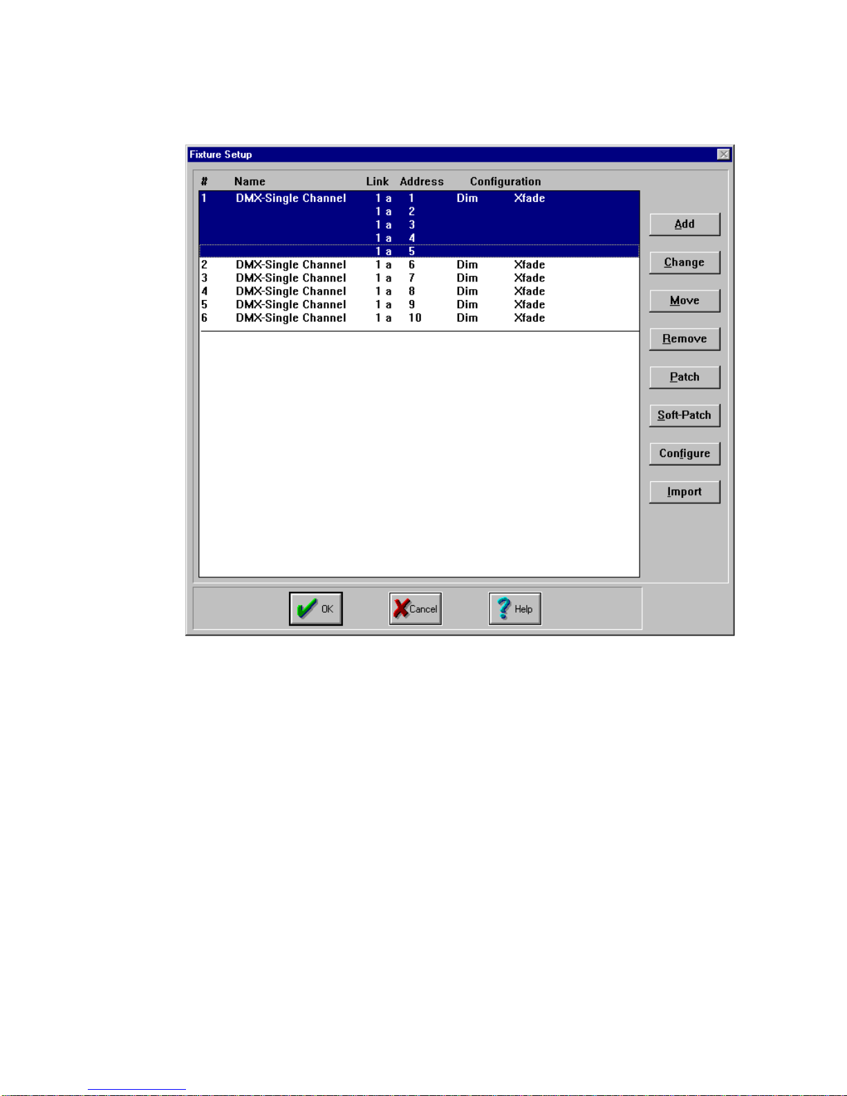
5. Repeat steps 1-3 as needed for additional soft-patching.
4-18
Status Cue
User’s Manual
Figure 4.19. Soft-Patched Channels Example
Page 99

Eliminating Soft-Patches
To eliminate a soft-patch, complete the following procedure:
1. Select all fixtures to eliminate from soft-patching.
4
2. Click the
box. Refer to Figure 4.21.
Change
Figure 4.20. Removing Soft-Patches
button. This brings up the
Change Fixture(s) To...
Chapter 4
dialogue
Fixture Setup
4-19
Page 100

Figure 4.21. Change Fixture(s) To... Dialogue Box
3. Select
DMX-Single Channel
and click the OK button. The soft-patched
fixture(s) will become single DMX channel(s) again. Refer to Figure 4.22.
Figure 4.22. Changed Soft-Patched Fixtures Example
4-20
Status Cue
User’s Manual
 Loading...