

Lightwave Communications USB ServerSwitch Product Manual

Product Manual
December 2001
Part Number 15.00.035

Lightwave Communications USB SERVERSWITCH
Lightwave Communications, Inc.
100 Washington Street Milford, CT 06460 USA
(800) 871-9838 • (203) 878-9838 • Fax: (203) 874-0157
Email: info@lightwavecom.com • Internet: www.lightwavecom.com
LCI Asia/Pacific
Postal address: P.O. Box 19 Glen Iris VIC 3146 Australia
Delivery address: 16 Network Drive Port Melbourne VIC 3207 Australia
+61 3 9646 1144 • Fax: +61 3 9645 3377
Email: sales@lightwavecom.com.au • Internet: www.lightwavecom.com.au
LCI Europe
Zaubzerstraße 11 Munich D-81677 Germany
+49-89-306-3810 • Fax: +49-89-306-3812
Email: office@lightwave.de • Internet: www.lightwave.de
USB ServerSwitch Product Manual
Copyright © 2001 by Lightwave Communications. All rights reserved. No part of
this copyrighted material may be reproduced in any form or by any means without
prior written permission of Lightwave Communications, Inc.
Printed in U.S.A.
USB ServerSwitch is a Trademark of Lightwave Communications, Inc.
Lightwave Communications is a subsidiary of Lantronix Inc.
Part Number 15.00.035, Revision History: December 7, 2001
Rev. A Initial Release
Page 2 of 25 December 2001

Lightwave Communications USB SERVERSWITCH
Table of Contents
1.0 USB ServerSwitch - Introduction.................................................................................4
USB ServerSwitch features:............................................................................................5
Specifications..................................................................................................................5
2.0 USB ServerSwitch - System Information...................................................................... 6
2.1 Video........................................................................................................................6
DDC2B Support..........................................................................................................6
2.2 Keyboard / Mouse....................................................................................................6
2.3 System Control.........................................................................................................7
3.0 On-Screen Menus.........................................................................................................8
Navigating the on-screen menus .................................................................................8
3.1 Main Menu...............................................................................................................8
Main Menu Options ....................................................................................................9
System Setup Options .................................................................................................9
3.1.1 Main Menu: Auto Scan...................................................................................10
3.1.2 Main Menu: Jump to Port... ............................................................................11
3.2 System Setup..........................................................................................................12
3.2.1 System Setup: Port Setup................................................................................13
3.2.2 System Setup: Menu Window Setup...............................................................14
3.2.3 System Setup: Server Window Setup..............................................................15
3.3 Front-panel LCD Display.......................................................................................15
Front Panel Controls..................................................................................................16
3.4 Error Messages.......................................................................................................16
4.0 Operational Safety......................................................................................................17
5.0 Installation .................................................................................................................18
STEP 1 -- Unpacking the Items.................................................................................18
USB ServerSwitch Rear Panel Connections.................................................................19
STEP 2 -- Initial Start-Up..........................................................................................19
STEP 3 -- Connecting CPUs.....................................................................................20
STEP 4 -- Power Up Sequence .................................................................................20
6.0 Cascading the USB ServerSwitch .............................................................................. 21
STEP 1 - Connect CONTROL Cable........................................................................22
STEP 2 - Connect Video Cascade Cables.................................................................22
STEP 3 - Turn the Auxiliary Unit On.......................................................................22
7.0 System Maintenance Features............................................................................... 23
7.1 Setting Factory Defaults.................................................................................... 23
7.2 Flash Update Procedure ....................................................................................23
Materials:...................................................................................................................24
Flash Update Steps:...................................................................................................24
www.lightwa vecom.com Page 3 of 25
Lightwave Communications USB SERVERSWITCH
1.0 USB ServerSwitch - Introduction
The USB ServerSw itch is an intelligent KVM switch for keyboard, high-resolution
video and mouse for a 2-User by 8-server configuration. The USB ServerSwitch
(for simplicity, it may be referred to as the “USBSS”) supports individual USB
keyboards and mice. The USB ServerSwitch has full-time keyboard and mouse
emulation to each PC or server. This assures th at there will be no interruptions or
interference to boot processes or other CPU activity. The video switching circuitry
is designed with state of the art video multiplexers that support high-resolution
graphics adapters with video resolutions of 1600 x 1200 pixels.
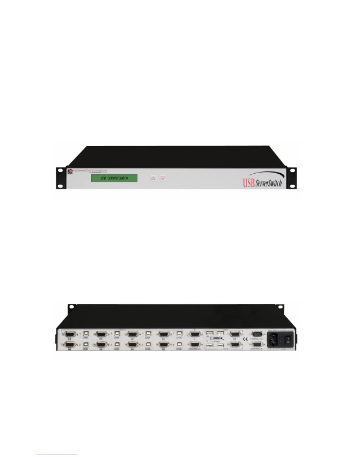
Figure 1: USB ServerSwitch - Front Panel
The USB Se rverSwitch front panel has a built-in 24 character, 2 line backlit LCD
display. The top line displays Port data f or the currently-selected server port, and
the bottom line is dedicated to real-time status monitoring. The USB ServerSwitch
can be controlled either through on-screen menus (see section 3.0) or directly
using the Up and Down buttons on the USBSS (see Section 3.3).
The USB ServerSwitch’s rear panel provides USB connections for Keyboard and
Mouse and HD15 Video for 8 Servers (Inputs), 2 USER/OUTPUT console
positions, and CONTROL and Video Cascade ports for expanded configurations
(see Section 6.0) that supports up to 64 connected servers. Also found on the back
panel is the AC power input, fuse, and Power Switch for the unit.
Figure 2: USB ServerSwitch - Rear Panel
The USB ServerSwitch is designed for rack mounting in a conventional 19-inch
equipment rack, requiring 1RU (1.75 inches) of rack height. The unit may also be
placed on a shelf; and the included rack mounting flanges are removable. The unit
is convection cooled and does not require a fan or air conditioning.
Page 4 of 25 December 2001

Lightwave Communications USB SERVERSWITCH
USB ServerSwitch features:
• Rack mountable chassis, 1RU, rack mounting flanges included with unit
• 8 server ports per chassis, expandable to 64 ports by cascading units
• Supports two Consoles with full Keyboard/Video/Mouse interfaces
• Standard Input and Output connections
o 4 pin USB-B keyboard and mouse connectors from Servers
o 4-pin USB-A connectors for Keyboard and Mice for Users
o Video: HD15 female video connectors
o DB9 Control connections (intra-unit)
Cascade Control In: DB9 female
Cascade Control Out: DB9 male
• Video Support for RGB, RGBS, RGBHV, up to 1600 x 1200 pixels
• DDC2B video record support
• Impedance-balanced RGB lines, 75 oh ms
• USB power sensing from server
• On-screen menus
• Backlit front-panel LCD display
• Non-volatile memory for server names & options
• Video cascade port for cascading USB ServerSwitch units
• Distance between cascaded USBSS's may be up to 50 feet
• Distance from CPU to USBSS = 25 feet
• Distance from USBSS to User Consoles = 25 feet
Specifications
Dimensions:
• Rack size: 19"
• Height: 1 RU, 1.75" (4.45cm)
• Width: 17.5" (44.45 cm)
• Depth: 11.75" (29.85cm)
Weight: 10.4 lbs (4.70 kg)
Shipping Weight: 15 lbs (6.8kg)
Operating Environment:
• 0°C (32°F) to 50°C (122°F)
• 10-90% humidity, non-condensing
Power Requirements:
• Input Power: 90-253 VAC, 47-63 Hz, fused at 4 amperes
• Equipped with IEC-type power connector and location-specific cordset
• Power consumption: 12 watts
www.lightwa vecom.com Page 5 of 25

Lightwave Communications USB SERVERSWITCH
2.0 USB ServerSwitch - System Information
2.1 Video
The USB ServerSwitch incorporates an active, high-bandwidth switch for graphics
adapter cards supporting resolutions up to 1600 x 1200 pixels. The system
supports DDC2B video records, and maintains a local copy of the video record for
each attached server (after a proper power-up sequence). A constant impedance
of 75 ohms is maintained on all video lines in the USBSS, so that the video signal
is not compromised by mismatched impedance. Monitor sense lines are also
transported by the USB ServerSwitch. The ID lines are buffered and passed f rom
the monitor to the attached graphics adapters in the servers.
Note: The USB ServerSwitch's USB interface is for discrete USB mice and
keyboards only, and will not support Monitors with USB-provided video controls.
DDC2B Support
The DDC2B video record is generated during the power-up of the system, and is
generated by each server that supports or requires the video record, or else
defaults to a generic VGA mode. The USBSS stores a copy of the DDC2B record
at each Server port, and when that server is switched to the User, that video record
information will be sent to the monitor for a proper video signal.
The video record is determined upon power-up of the system by checking the
video signal with the monitor connected to the User A port, and then the User B
port. If monitors are changed at a later date, it may be necessary to shut down the
USB ServerSwitch and/or the servers to regene rate the proper DDC2B record.
If using DDC2B, it is recommended that both User A and User B have similar video
monitors at their stations, since the DDC2B only supports one video record per
server.
2.2 Keyboard / Mouse
The USB ServerSwitch is an intelligent USB switch for the keyboard and mouse.
Each port emulates the keyboard and mouse fully, allowing an attached server or
PC to boot without having been previously selected. Power for each connected
device is monitored from the USB port.
Note: The USB ServerSwitch's keyboard and mouse interface is for discrete USB
mice and keyboards. It does not support graphics tablets, scanners, modems,
drives, hubs or other composite USB devices. Each USB-A receptacle on the
USBSS will support one USB mouse or USB keyboard.
If there is no connection on a USB server port, a status message "Inactive port" will
be displayed on the front panel display. The other attached servers are not
affected because of the keyboard and mous e emulation.
Each port maintains a local copy of the keyboard and mouse configuration. USB
Port numeration is maintained even when the user has de-selected a port. When
Page 6 of 25 December 2001

Lightwave Communications USB SERVERSWITCH
the user switches from one port to another, the keyboard is set up just as it was
prior to switching to another port. The mouse behaves in a similar manner.
2.3 System Control
The USB ServerSwitch is controlled either by using the UP and DOWN arrows on
the front panel of the unit or via On-Screen Menus from their Console (Keyboard,
Monitor and Mouse).
The USBSS is a transparent device to the User. The User (of which there may be
one or two) can select which server they wish to access from their Console, from
up to 8 connected Servers. In cases where two or more USBSS units have been
cascaded, additional Servers can be accessed by the two Users, up to a maximum
of 64 Servers (8 units cascaded in all).
To access the USBSS’s switching capability, the User must “wake up” the onscreen display to control the system by pressing both ‘Cntl’ keys simultaneously
(referred to as ‘Cntl-Cntl’), or press the Scroll Lock key twice (within one second)
on their keyboard.
If the system administrator is near the USBSS (for example, in a backroom
location), the sysadmin may instead select a server by using the Up and Down
buttons on the front of the unit. The display will scan through which Servers are
available, if auto-scan is active. Server selection can also be accomplished
manually by pressing the Up arrow or Down arrow buttons. To select between
User A and User B, press both Up and Down buttons on the front panel of the
USBSS at the same time to shift between the two users.
www.lightwa vecom.com Page 7 of 25

Lightwave Communications USB SERVERSWITCH
3.0 On-Screen Menus
On-screen Menus are used for two purposes:
• Server Port selection for a Console
• System setup programming for the USB ServerSwitch
On-Screen Menus are displayed on the User's monitor. Either Console may
administer the system, but only one user may edit the setup at a time.
NOTE: While in the on-screen menu mode, the "Caps Lock", "Num Lock", and
"Scroll Lock" LEDs will flash on the User Console’s keyboard.
Navigating the on-screen menus
• Press both Control keys (Cntl-Cntl) to access the on-screen menus, or
press the Scroll Lock key twice (within one second)
• Up Arrow/Down Arrow
• + and - keys on number pad
• Enter (select or scroll through options)
• Esc to exit, or to back up one level
• Most options have a single-character hot-select key, highlighted and
capitalized on the screen. Press that letter to select that option.
3.1 Main Menu
Pressing and releasing both CONTROL buttons (Ctrl-Ctrl) on either Console's
keyboard will bring up the main menu of the USB ServerSwitch.
Lightwave Communications Inc.
Curr: File Server 1
USBss System Setup
no Auto scan
Jump to port...
Disabled
File Server 1 1
File Server 2 2
Print Server 3
Email Server 4
Engineering 5
Enterprise 6
Firewall 7
Fax Server 8
Next unit Esc exits
Note: This window will show the current server port (e.g., Curr: File Server 1).
Window color settings may be different than above.
Page 8 of 25 December 2001
 Loading...