

Page 1
Lightwave Communications, Inc.
Part Number 15.00.038
Revision A
SCS3230
SSH Option for Console Server 3200
System Administrator's Guide
NOTE: Use this Guide and the ConsoleServer 3200 Manual, PN 15.00.017 for any new installation
May 2002
Page 2

ConsoleServer 3200 System Lightwave Communications
Copyright & Trademark
© 2002, Lightwave Commu nications, a Lantronix Company. All rights reserved. No part of the
contents of this book may be transmitted or reproduced in any form or by any means without the
written permission of Lantronix. Printed in the United States of America. Also electronically
distributed via Adobe PDF file format.
Ethernet is a trademark of XEROX Corporation. UNIX is a registered trademark of The Open Group.
Windows 95, Windows 98, Windows 2000, and Windows NT are trademarks of Microsoft Corp.
Netscape is a trademark of Netscape Communications Corporation. Adobe Acrobat and PDF are
trademarks of Adobe Corporation. Other trademarks and service marks are held by their respective
owners.
Lightwave Communications, Inc. (LCI), A Lantronix Company
100 Washington Street
Milford, CT 06460 USA
Phone (800) 871-9838 • (203) 878-9838
Fax: (203) 874-0157
Email: info@lightwavecom.com
Internet: www.lightwavecom.com
Lantronix
15353 Barranca Parkway
Irvine, CA 92618 USA
Phone: (949) 453-3990
Fax: (949) 453-3995
Internet: www.lantronix.com
Rev. A ii www.lightwavecom.com
Page 3

A Lantronix Company SCS3230 System Administrator's Guide
Disclaimer & Revisions
Operation of this equipment in a residential area is likely to cause interference in which case the user,
at his or her own expense, will be required to take whatever measures may be required to correct the
interference.
Attention: This product has been designed to comply with the limits for a Class A
digital device pursuant to Part 15 of FCC Rules. These limits are designed to provide
reasonable protection against such interference when operating in a commercial
environment. This equipment generates, uses, and can radiate radio frequency energy,
and if not installed and used in accordance with this guide, may cause harmful
interference to radio communications.
Changes or modifications to this device not explicitly approved by Lantronix will void the user's
authority to operate this device.
The information in this guide may change without notice. The manufacturer assumes no
responsibility for any errors that may appear in this guide.
Date Rev. Part No. Comments
April
2002 A (Preliminary)
May
2002
A Incorporated Addendum info on root -level password, and binary
15.00.038 System Administrator's Guide for SCS3230, an optional
enhancement to the ConsoleServer 3200 system.
update file location (pp.9, 25, 39).
15.00.038 iii May 2002
Page 4

ConsoleServer 3200 System Lightwave Communications
Declaration of Conformity
(according to ISO/IEC Guide 22 and EN 45014)
Manufacturer’s Name & Address:
Lightwave Communications, a Lantronix Company
100 Washington Street, Milford, CT 06460 USA
Declares that the following product:
Product Name & Model: Lightwave Console Server 3200
Conforms to the following standards or other normative documents:
Safety:
EN60950: 1992+A1, A2, A3, A4, A11
Electromagnetic Emissions:
EN55022 Class A: 1998 (CISPR 22, Class A: 1993, A1: 1995, A2: 1996)
EN1000-3-2/A14: 2000
EN10003-3: 1994
Electromagnetic Immunity:
EN55024: 1998 Information Technology Equipment-Immunity Characteristics:
EN61000-4-2: 1995 Electro-Static Discharge Test
EN61000-4-3: 1996 Radiated Immunity Field Test
EN61000-4-4: 1995 Electrical Fast Transient Test
EN61000-4-5: 1995 Power Supply Surge Test
EN61000-4-6: 1996 Conducted Immunity Test
EN61000-4-8: 1993 Magnetic Field Test
EN61000-4-11: 1994 Voltage Dips & Interrupts Test
Supplementary Information:
This Class A digital apparatus complies with Canadian ICES-003 (CSA) and has been verified as
being compliant within the Class A limits of the FCC Radio Frequency Device Rules (FCC Title 47,
Part 15, Subpart B CLASS A), measured to CISPR 22: 1993 limits and methods of measurement of
Radio Disturbance Characteristics of Information Technology Equipment. This product also complies
with the requirements of the Low Voltage Directive 72/23/EEC and the EMC Directive 89/336/EEC.
The Console Server 3200 carries the CE mark since it has been tested and found compliant with the
following standards:
Safety: EN 60950
Emissions: EN 55022 Class A
Immunity: EN 55024
Rev. A iv www.lightwavecom.com
Page 5

A Lantronix Company SCS3230 System Administrator's Guide
Table of Contents
1: Product Description______________________________________________________9
1.1 Quick Start _____________________________________________________ 9
1.2 Upgrade Description _____________________________________________10
1.3 System Features ________________________________________________10
1.4 Hardware Features _______________________________________________ 11
1.5 3230 Network/Control Card________________________________________12
1.5.1 10/100 Port (Network) ______________________________________14
1.5.2 TERM Port (Console)_______________________________________15
1.6 Backup and Restore Commands _____________________________________15
2: System Overview________________________________________________________16
2.1 Connect Up to Thirty-two RS-232C Compatible Ports_____________________16
2.2 128K FIFO Audit Trail ___________________________________________16
2.3 Connections ___________________________________________________16
2.4 Security Passwords ______________________________________________17
2.5 Interface ______________________________________________________17
3: System Components _____________________________________________________18
3.1 3200 Chassis ___________________________________________________18
3.1.1 Power Supply Module ______________________________________18
3.1.2 3200 Switch Cards _________________________________________18
3.2 Device Cards ___________________________________________________ 19
3.3 Access Cards ___________________________________________________ 19
3.3.1 NETWORK / CONTROL Ca rd________________________________19
3.3.2 CHANNEL EXTENDER Cards _______________________________20
3.3.3 TERMINAL Cards _________________________________________ 20
3.3.4 3200 Network Cards ________________________________________ 20
3.3.5 3200 10/100 Network Cards __________________________________21
3.3.6 Modem Card _____________________________________________21
4: Installation Instructions __________________________________________________22
4.1 Items in a SCS3230 Kit ___________________________________________22
4.2 Move Database from your CS3200 to SCS3230__________________________23
4.2.1 Backup Procedure of your CS3200 System _______________________23
4.2.2 Restore Procedure _________________________________________23
4.2.3 To RESTORE from a 3200 to a 3230 ____________________________ 24
4.2.4 LCI Update ______________________________________________25
4.3 Connecting to the TERM Port ______________________________________26
5: Connecting Equipment to the SCS3230 _____________________________________27
5.1 Terminal Card __________________________________________________ 27
5.2 NETWORK / CONTROL Card _____________________________________28
5.3 Modem Card ___________________________________________________ 28
5.4 Device Card ___________________________________________________29
15.00.038 v May 2002
Page 6

ConsoleServer 3200 System Lightwave Communications
6: SCS3230 Setup Script and System Administration ___________________________33
6.1 Power-up Sequence and Basic Use of the Administrator Functions ___________34
6.1.1 Logging In, Serial Connection_________________________________35
6.1.2 Logging In, Network Connection ______________________________35
6.1.3 Logging Out______________________________________________36
6.1.4 System Help (Command List) _________________________________37
6.1.5 Abbreviations_____________________________________________38
6.2 Sys Admin vs. root access _________________________________________39
6.3 Setup Script ____________________________________________________ 40
6.3.1 Hostname and IP Address____________________________________41
6.3.2 Timezone (Clock)__________________________________________44
6.3.3 Configure DNS ___________________________________________46
6.3.4 Hosts___________________________________________________48
6.3.5 Services_________________________________________________49
6.3.6 Syslog __________________________________________________50
6.3.7 SSH Logins ______________________________________________ 51
6.3.8 TELNET logins ___________________________________________52
6.3.9 NTP Daemon_____________________________________________52
6.3.10 Configure the Firewall _____________________________________53
6.3.11 Firewall Reject Method_____________________________________55
6.3.12 Ping Attempts ___________________________________________55
6.3.13 Confirm Changes _________________________________________57
6.3.14 SAVE Command _________________________________________58
7: Creating and Managing Users_____________________________________________59
7.1 Adding a User ID _______________________________________________59
7.2 Editing a User ID________________________________________________61
7.3 Listing User IDs ________________________________________________61
7.4 Deleting a User ID _______________________________________________ 63
7.5 Devices Command_____________________________________________63
7.6 Terminals Command___________________________________________65
7.7 Network Commands ____________________________________________65
7.8 Modem Command _______________________________________________66
7.9 Status Commands _______________________________________________67
7.9.1 CONNECTIONS Command ___________________________________ 67
7.9.2 LISTCARDS Command _____________________________________68
7.9.3 VERSION Command _______________________________________68
7.9.4 INFO Command __________________________________________69
7.9.5 POWERSTATUS Command ___________________________________ 70
7.9.6 LOG Command____________________________________________70
7.10 Sys Admin Session Management Commands ___________________________71
7.10.1 LINESPERPAGE Command_________________________________72
7.10.2 TIMEOUT Command ______________________________________72
7.11 Breaking User Connections ________________________________________72
7.11.1 BREAK Command ________________________________________73
7.11.2 FORCELOGOUT Command __________________________________ 73
7.11.3 TELNETTIMEOUT Command _______________________________74
7.11.4 MODEMTIMEOUT Command_________________________________74
Rev. A vi www.lightwavecom.com
Page 7

A Lantronix Company SCS3230 System Administrator's Guide
8: User Access and Interface ________________________________________________75
8.1 Terminal Card __________________________________________________ 75
8.2 Network Card __________________________________________________75
8.3 Modem Card ___________________________________________________ 76
8.3.1 The Bye Command ________________________________________76
8.4 Overview of Commands ___________________________________________ 77
8.5 Logging In and Changing Passwords _________________________________79
8.6 Logging Out ___________________________________________________80
8.7 Checking Connections ____________________________________________80
8.8 Selecting a Device Port ___________________________________________81
8.9 Listening to a Server Session _______________________________________82
F2 PULL-DOWN MENU TO LISTEN TO A DEVICE PORT PART 2 ________83
8.10 Direct Mode ___________________________________________________84
8.10.1 Direct Mode Escape Sequence _______________________________84
8.11 Using the Buffer ________________________________________________85
9: The Break Generation Sequence___________________________________________88
10: Displaying System Information___________________________________________89
11: Front Panel Display Information:_________________________________________90
12: Appendix A – Command Abbreviations ___________________________________94
13: Appendix B – Hexadecimal ASCII Code ___________________________________96
15.00.038 vii May 2002
Page 8

ConsoleServer 3200 System Lightwave Communications
For Your Notes
Rev. A viii www.lightwavecom.com
Page 9
A Lantronix Company SCS3230 System Administrator's Guide
CONTROL
1: Product Description
The SCS3230 is a ConsoleServer 3200 (or CS3200) that has been upgraded for enhanced
security and control capabilities, including SSH capabilities required for today's secure server
environment, and network features such as LDAP and NIS. The upgrade is available as a kit, or
the individual parts (cards, cables, etc.) can be ordered separately.
I
0
I
0
TERMINAL NETWORK SWITCHTERMINAL NETWORKMODEM
AA
BB
CC
DD
SWITCH
DEVICE DEVICE DEVICEDEVICEDEVICEDEVICE
CC CCC C
DEVICE
DEVICE
AAAAAA
DDDDDD
AAA
BBBBBBBB
CC
BDD
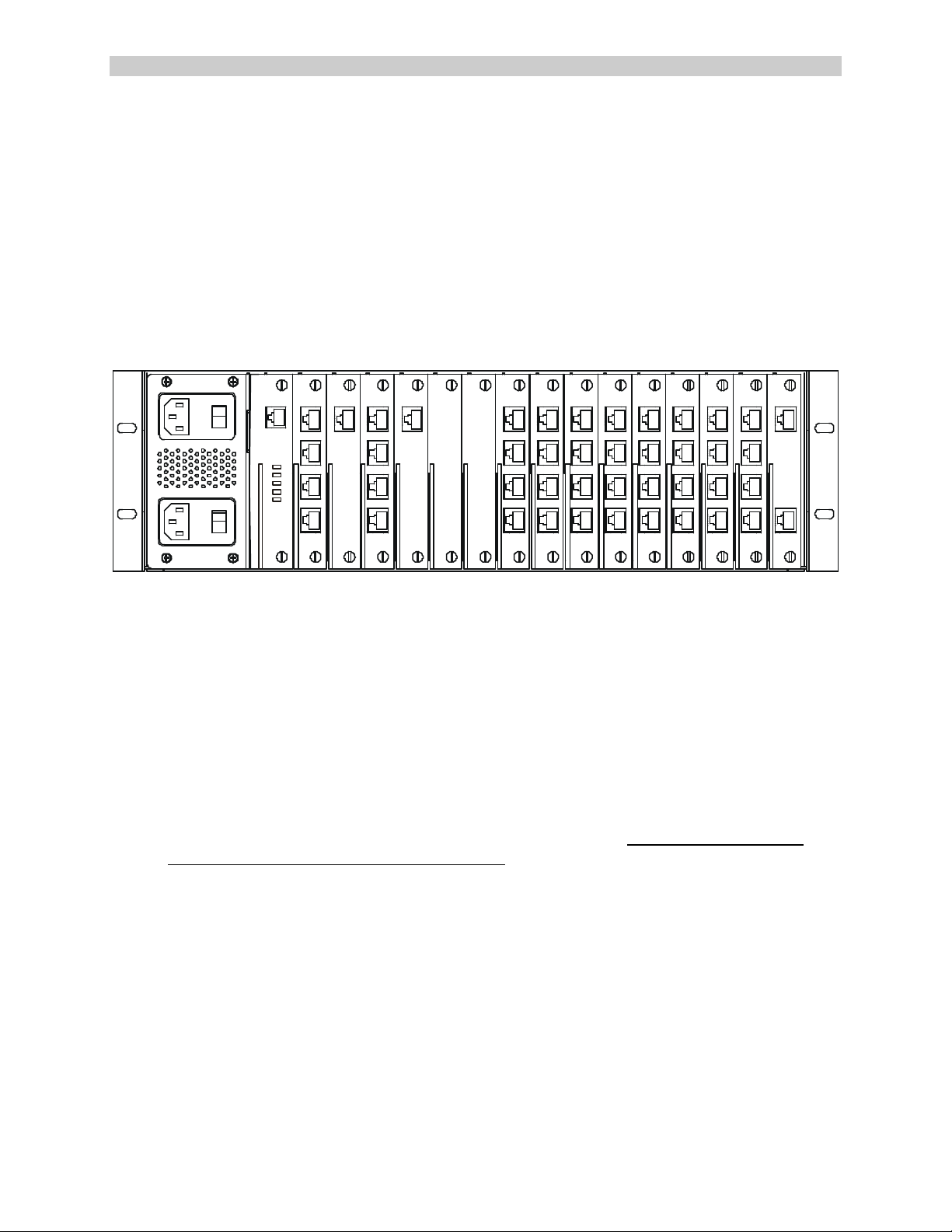
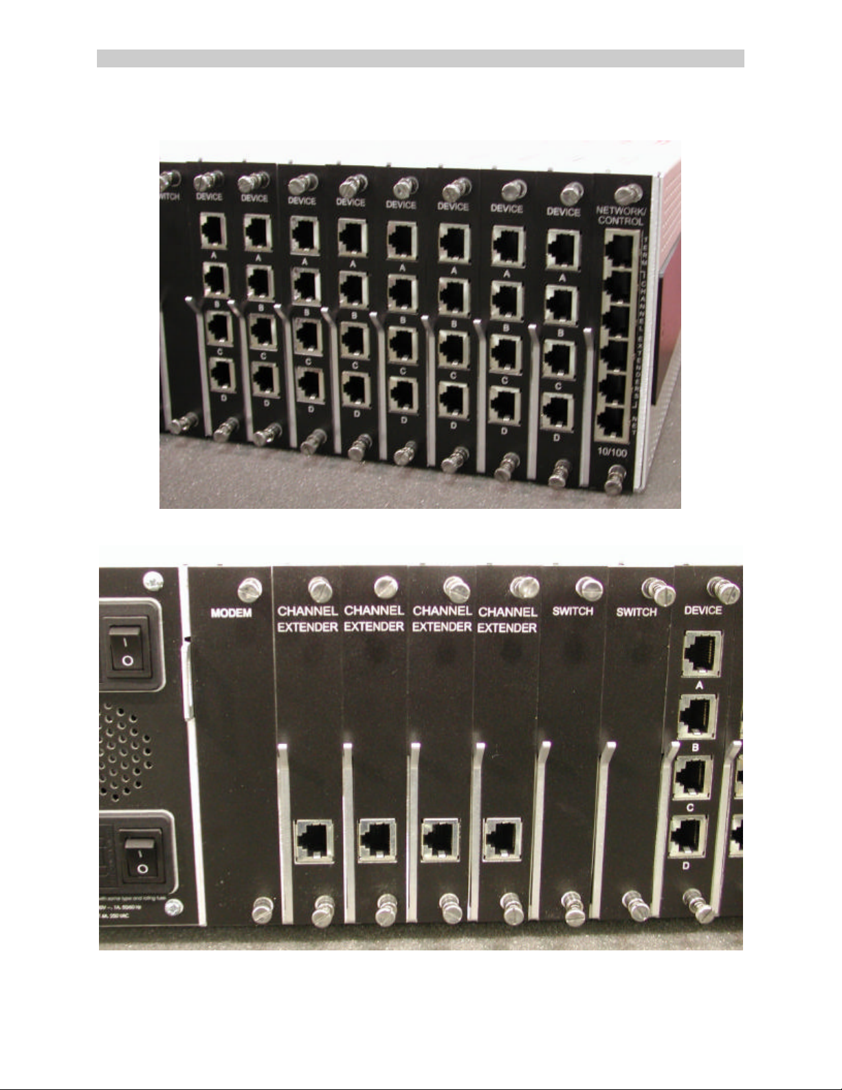
Fig. 1 Rear View of original Console Server 3200 - notice Control Card to far right
The SCS3230 upgrade replaces the CONTROL card of the 3200 with a new 10/100 BaseT
NETWORK and CONTROL card which includes a Linux-based operating system, and also
replaces the NETWORK and TERMINAL cards of the 3200 with CHANNEL EXTENDER cards.
1.1 Quick Start
Overview of Upgrading from a CS3200 to a SCS3230 (all covered in this manual):
1. Backup the Database of your existing CS3200 System.
2. Obtain the SCS3230 Kit, which includes the cards, cables and this manual.
3. Locate the firmware updates for the DEVICE cards; they are stored in the /lci/bin
directory on the NETWORK/CONTROL card. You may also download the update files
from the Lightwave FTP site. DEVICE cards MUST be updates to Version 4.03 firmware.
4. Remove the CS3200 from service.
5. Remove the CONTROL card, the TERMINAL card(s) and the Network or 10/100 card(s)
6. Install the 3230's NETWORK/CONTROL card in place of the CONTROL card.
7. Install the four CHANNEL EXTENDERS in place of the TERMINAL or NETWORK cards.
8. Connect the four cables for the CHANNEL EXTENDERS.
9. Turn the System On, and administer the system using the TERM port. Set up your IP
network connection information to get that operating.
10. RESTORE your CS3200's database into the SCS3230 system.
The SCS3230 system should be fully operational at this point.
15.00.038 - 9 - May 2002
Page 10
ConsoleServer 3200 System Lightwave Communications
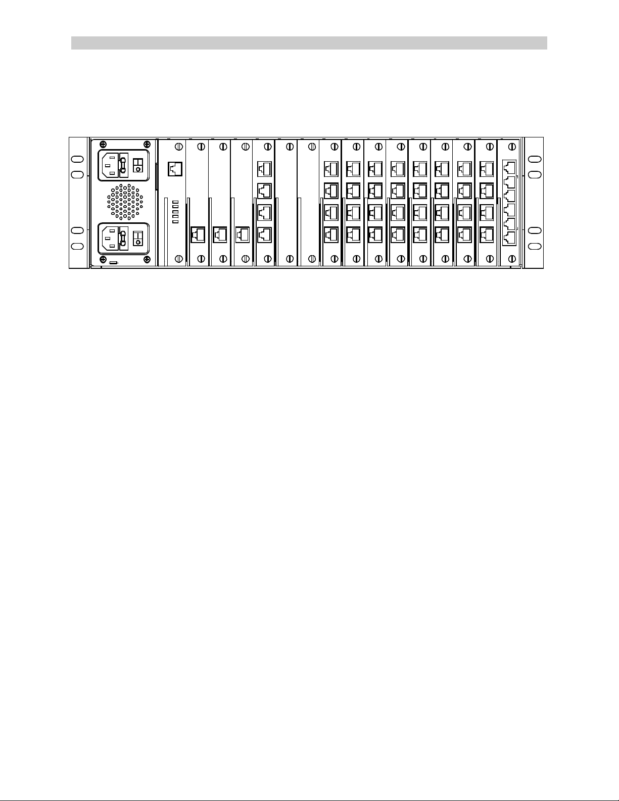
1.2 Upgrade Description
The SCS3230 uses most of the same cards as the CS3200, and uses the CS3200 chassis. The
SCS3230 is below. Notice the SCS3230's NETWORK/CONTROL card to the far right.
DEVICE
NETWORK/
CONTROL
10/100
T
E
R
M
C
H
A
N
N
E
L
E
X
T
E
N
D
E
R
S
N
E
T
Caution! Replace with same type and rating fuse.
100-240V ~, 1A, 50/60 Hz
T 4A, 250 VAC
MODEM
CHANNEL
EXTEND ER
CHANNEL
CHANNEL
EXTENDER EXTENDER
TERMIN AL
A
B
C
D
SWITCH
SWITCH
DEVICE DEVICE DEVICEDEVIC EDEVICEDEVICE
A A AA A A
B B B B B B B B
C C CC C C
D D D D D D
DEVIC E
A A
C C
D D
Fig. 2 Rear View of SCS3230 - notice the NETWORK / CONTROL card in far right slot.
Also note that this diagram shows three (3) Channel Extenders and one Terminal card in
slots B through E, and 8 DEVICE cards.
1.3 System Features
The SCS3230 system is a Linux-based Console Server offering secure IP network -based
connections to up to 32 connect ed devices via EIA-232 protocol. Linux administrators will find
familiar commands and should need little guidance on administering the SCS3230 to co -operate
in their server installation.
System users will not encounter any differences in operation. The commands and functions of
the SCS3230 are designed to minimize any conversion issues.
The SCS3230 offers the following important features (many of which are also found in the
CS3200 product):
• Hot-Swappable cards
• Dual Redundant Power Supplies
• 10/100 IP Network Interface
• Connect up to 32 RS-232 serial devices
• ID / Password Security, configurable access rights
• OpenSSH version 2 security
• Open LDAP
• NIS capable for remote database rights
• No unintentional break will ever be sent to attached servers
• Local access through TERM port (the 3230's Console port)
• Field upgradeable Flash memory
• User programming interface for simple administration and setup
Rev. A - 10 - www.lightwavecom.com
Page 11

A Lantronix Company SCS3230 System Administrator's Guide
1.4 Hardware Features
• 3RU tall (5-1/4 inches) rack -mountable Server
• One (1) 10/100 baseT Network Port for connection to your IP network
• Up to 32 serial DEVICE ports, RS232, connected via Category 5 (RJ45) wiring
• One (1) serial TERMINAL port, for VT100 console or PC with emulation
• 128KB-per-port Buffer Memory for DEVICE ports
• Front Panel multi-line backlit LCD display and pushbutton controls
• 128MB FLASH Memory, 128MB RAM
• * Redundant Power Inputs (chassis dependant)
• Optional Analog Modem for dial up access (non-secure)
• Power Options: Universal AC (100-240V) or -48VDC
* Some early CS3200 Chassis employ a single AC Power Input module. The Power Module is
field-replaceable to provide redundant power capabilities, if required.
The SCS3230 is one of the most versatile network administration tools available today,
allowing as many as 17 simultaneous users to access up to 32 connected devices via
the RS-232C serial protocol. Pull -down menus help users navigate through all the
functions of the SCS3230, creating an easy-to-use way to access system resources.
The SCS3230 consists of eight device card slots, two switch card slots, four access card slots,
one modem slot and one Network/Control slot. The power supply slot contains two independent
power supplies for redundant operation. The basic system consists of the power supply
module, two switch cards, the Network / Control card, and in most cases, four Channel Extender
Cards. The remaining card slots are populated according to the application requirements.
All system parameters are stored in non-volatile data flash memory. This data flash memory is
organized such that there is always a complete copy of all data. Typical stored information
includes the users’ identities, user passwords, port parameters (such as baud rate, device
name, etc.) and other system information. The data flash memory allow for a maximum of 200
user profiles to be stored, along with the parameters for all cards. System parameters may be
backed up and restored from a local serial connection.
An important feature of the SCS3230 is the ability to re-configure the system hardware and
software without turning off the power. The system boards have circuitry that allows them to be
'hot swapped' so the system may be expanded at any time while in use.
System updates can be accomplished via software upload to the system. For most updates, the
system need not be restarted or taken out of service. Some operations or updates (e.g.,
Network update) may require the network ports be restarted.
15.00.038 - 11 - May 2002
Page 12
ConsoleServer 3200 System Lightwave Communications
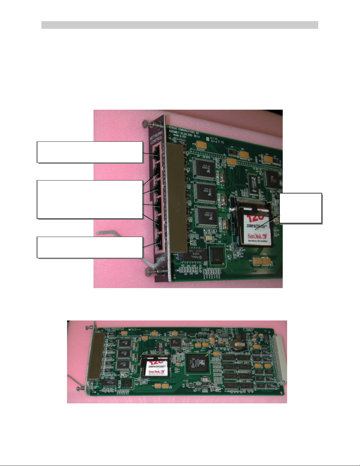
FLASH
TERM
(Console) connector
,
Four
CHANNEL EXTENDER
NETWORK
10/100 BaseT
1.5 3230 Network/Control Card
The SCS3230 offers the following benefits and features over the conventional CS3200 product:
• Linux-based Secure Console Server using OpenSSH v2
• ID / Password Security, configurable access rights
• One RS-232 Terminal port (for your local Console)
• 10/100 Network Port (TCP/IP) -- an option for the CS3200
RJ45, for RS232 terminal
ports - use four (4) CAT5 cables
to individual
Channel Extender cards
Memory
Device
IP network connection
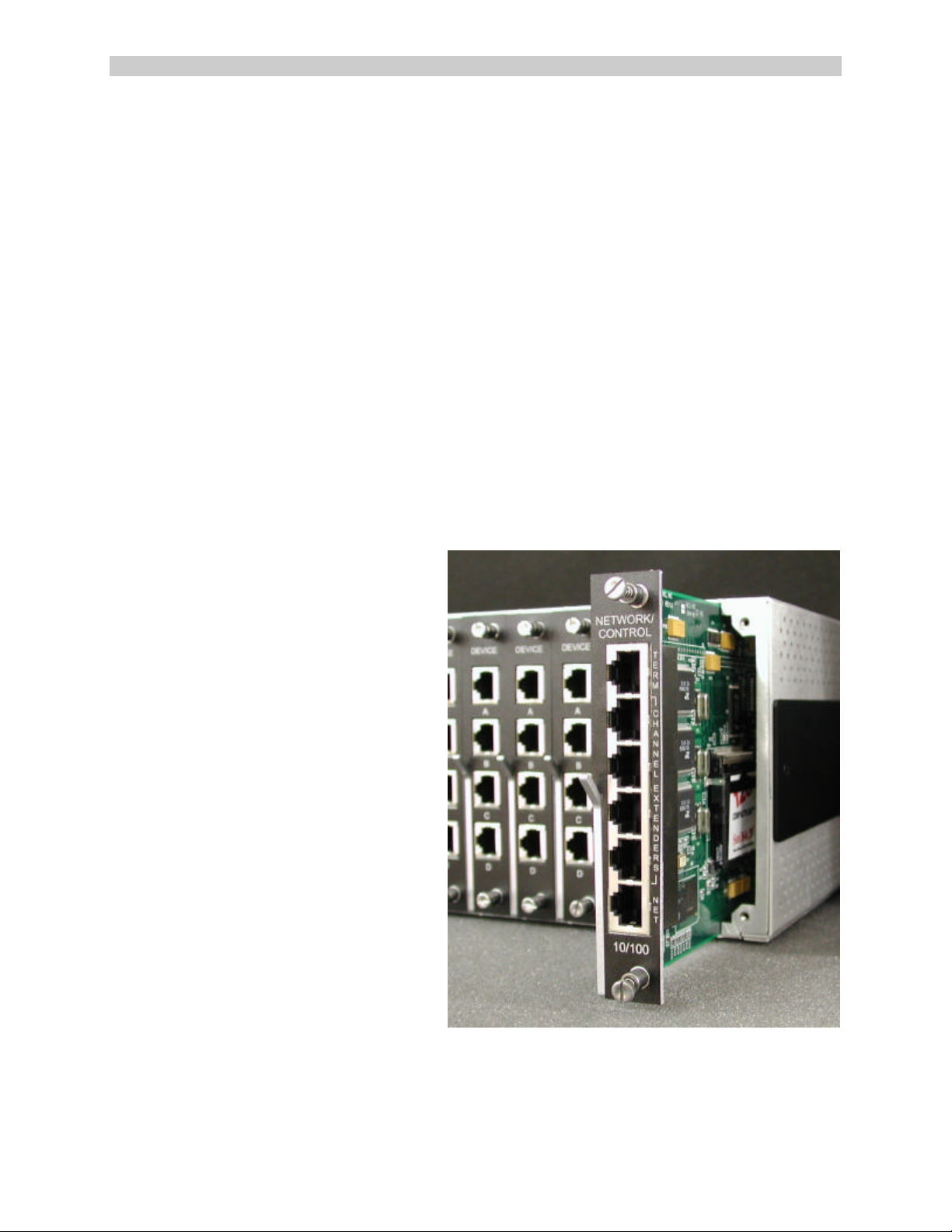
The SCS3230 replaces the standard CONTROL card with the new combination NETWORK /
CONTROL card, and fills the four Network / Terminal Card slots with "Channel Extender" cards.
The Channel Extenders are used by the new Network / Control card to extend the number of
Rev. A - 12 - www.lightwavecom.com
Page 13
A Lantronix Company SCS3230 System Administrator's Guide
channels available to the 10/100 IP network connection. [The Channel Extender cards are the
same as those used with the CS3200's 10/100 Network card.]
The NETWORK / CONTROL Card replaces the CONTROL card (far right slot) in 3200
The (4) Channel Extenders are used in place of the NETWORK or TERMINAL cards.
15.00.038 - 13 - May 2002
Page 14

ConsoleServer 3200 System Lightwave Communications
Four (4) 24-inch long CAT5 cables (PN 200.1061; straight-through, fully pinned) are used
between the Channel Extenders and the NETWORK / CONTROL card. One cable is used to
connect each of the Channel Extenders in Slots B through E to the corresponding port (see
below) on the new Network/Control Card.
DEVICE
NETWORK/
CONTROL
10/100
T
E
R
M
C
H
A
N
N
E
L
E
X
T
E
N
D
E
R
S
N
E
T
Caution! Replace with same type and rating fuse.
100-240V ~, 1A, 50/60 Hz
T 4A, 250 VAC
MODEM
CHANNEL
EXTENDER
CHANNEL
CHANNEL
EXTENDER EXTENDER
TERMINAL
SWITCH
SWITCH
A
B
C
D
DEVICE DEVICE DEVICEDEVICEDEVICEDE VICE
A A AA A A
B B B B B B B B
C C CC C C
D D D D D D
DEVICE
A A
C C
D D
If a Terminal Card remains in the 3230 system, that Channel Extender port of the Network /
Control Card is not used. Shown above, Network Slot E's Channel Extender position is
"unused"; and this unnecessary cable would not be installed in that position.
1.5.1 10/100 Port (Network)
The 10/100 BaseT Network connection is accessible on the bottom RJ45 connector on the
NETWORK / CONTROL card.
Rev. A - 14 - www.lightwavecom.com
Page 15

A Lantronix Company SCS3230 System Administrator's Guide
1.5.2 TERM Port (Console)
A Terminal port, or Console (labeled TERM) is available at the top RJ45 connector on the
NETWORK / CONTROL Card. This is an EIA -232-compliant terminal position, typically used for
System Administration purposes.
The TERM port on the NETWORK/CONTROL card is fixed at 9600 baud, 8 data bits, No Parity,
and one Stop bit (9600 / 8 / N / 1) and is a DCE device.The TERM port has a higher Terminal
priority than the 10/100 Network Port on this card, and can be used for forced logout of
abandoned or other undesirable connections.
1.6 Backup and Restore Commands
The SCS3230 system is fully compatible with the "Backup and Restore" capabilities of the
CS3200, so transferring your user database from your existing CS3200 into the new SCS3200
hardware is supported.
15.00.038 - 15 - May 2002
Page 16

ConsoleServer 3200 System Lightwave Communications
2: System Overview
For simplicity, we will discuss the features and capabilities of the SCS3230 as if it were a new
and different system, not merely an upgrade to a ConsoleServer 3200. The SCS3230 is
designed to operate as closely to the original ConsoleServer3200 as possible from a user's
perspective, but still provide the capabilities needed for the secure server environment.
Existing 3200 customers maintain their investment and can offer enhanced security and control
for their terminal server systems. Existing users will not require retraining since all commands
and features of the SCS3230 option are the same as found in the CS3200. Even the upgrade
process accepts the existing site database for rapid deployment of the SCS3230 equipment.
2.1 Connect Up to Thirty-two RS-232C Compatible Ports
The SCS3230 is plug-compatible with any RS-232C device , DTE or DCE. These include a
variety of network servers, routers, or any other LAN/WAN computers on the network.
Connections are made by routing the device signals through the switch cards to the appropriate
user interface port.
2.2 128K FIFO Audit Trail
The SCS3230 stores the equivalent of approximately 200 screens worth of data (128K) per
device port in a true FIFO buffer for each DEVICE port. This data may be viewed 'off-line' at
any time by users accessing the device port buffer.
Should more than 128K of data be received in a buffer, the oldest data will be discarded, in the
amount of the 'overflow'. By operating in this fashion, the most recent data is collected and the
largest amount of data that can be saved will be maintained.
2.3 Connections
The system is capable of 17 simultaneous full-duplex connect ions to the connected devices.
The administration functions may be accessed through a local serial connection or through a
network connection. The NETWORK / CONTROL card (with a full complement of four Channel
Extender cards) supports up to 16 users connections plus one connection to the administration
functions. The NETWORK / CONTROL card also provides one TERM port (for a System
Administrator's serial Console)
The TERMINAL cards (a 3200 access card) may be used for applications requiring additional
local serial terminals. Each Terminal Card is installed in place of one of the Channel Extender
Rev. A - 16 - www.lightwavecom.com
Page 17

A Lantronix Company SCS3230 System Administrator's Guide
cards. By reducing the number of Channel Extender ports, the maximum number of available
connections for 10/100 network access is reduced by four sessions for each Terminal Card
installed. Illustrations showing a mixture of Channel Extender cards and Terminal Cards are
found on pages 11 and 16 of this Guide.
An optional MODEM connection is also available, however its connections are not 'secure' and
its use is not recommended except in those instances when security will not be compromised by
dial-in access using the modem. The SCS3230's modem connection is not subject to the Linux
security controls of the other access ports.
2.4 Security Passwords
The System Administrator may define up to 200 user profiles. Each user is assigned a unique
password by the system administrator. The system forces the user to change the password the
first time the user attempts to connect to any servers. After the users have changed their
passwords, the system will not prompt for a change. The users change their passwords at
whatever interval they feel is necessary.
The operating system is subject to Linux security constraints, including sysadmin and root level
security. Users cannot access the sysadmin layer or the root layer of the system.
2.5 Interface
Interfaces to the DEVICE and TERMINAL cards are all RS-232C compliant. These ports are
configured through the TERM port on the NETWORK / CONTROL card using a local Console,
or via network connection through your TCP/IP network. All system access is password
protected.
Each DEVICE port and TERMINAL has settings for baud rate, stop bits, parity, number of data
bits, flow control, and port type (i.e., DTE or DCE). The TERM port (for your Console) on the
NETWORK / CONTROL card has a fixed data format of 9600 / 8/ N / 1, and DCE.
The NETWORK / CONTROL card connects over a network using TCP/IP on 10- or 100-baseT
at 10/100 Mbits (auto-negotiating). The 10/100 port on this card is assigned an IP address, a
subnet mask, a default gateway, and an optional secondary destination path by Conso le
configuration using the TERM port on this card during the initial setup of the system.
The optional MODEM card connects directly to a conventional modular phone jack (RJ11) to
interface with a telephone network. The sys admin may designate a modem initialization string,
or may use the default modem initialization string, which allows auto-answering on one ring. The
modem provides card-edge visual status indicators.
Note: For 'secure' installations, the Modem should not be used . Modem access is not
encrypted and/or secure and could allow unauthorized access to system information. However,
if modem access is limited to internal administrative access, the modem may provide an
additional means of system access in the event your network is down.
15.00.038 - 17 - May 2002
Page 18

ConsoleServer 3200 System Lightwave Communications
3: System Components
Each SCS3230 consists of three major components: the 3200 system chassis, 3200 DEVICE
cards, and 3200 access cards. The 'access cards' include the new 3230 NETWORK/CONTROL
card, which is the heart of the SCS3230 product, and makes it operate a bit differently.
Note: The 3200's NETWORK card and 10/100 Network card are NOT supported by the
SCS3230 NETWORK / CONTROL card. The NETWORK/CONTROL card incorporates its own
10/100 Network port.
3.1 3200 Chassis
The chassis contains a front-panel LCD for quick system information that is available at all
times. Two front panel buttons allow display selection and paging through displays (see
section 10.0 for more information).
The second major component of the chassis is the power supply module. This module contains
two independent supplies, each capable of sustaining the system should one supply fail or lose
its power input. The Power Supply module also incorporates the system fan. The AC power
module has two front-panel switches (one for each supply) with replaceable fuses in their IECtype connectors. The DC power module provides a single On/Off switch.
The third and last component of the chassis is the SWITCH card set. The switch cards connect
the access cards to the device cards, with a maximum of 17 simultaneous connections using all
available terminal, network, and modem ports.
3.1.1 Power Supply Module
The SCS3230 may be equipped with either an AC power module or a DC power module. The
power module may be field-swapped (although is not hot-swappable) if the available power
source requirements change.
The Power Module provides two discrete electrical inputs to the system. Either power input
supports a fully-loaded chassis, and switching between power inputs is automatic if one source
fails or is turned off.
3.1.2 3200 Switch Cards
Two 3200 SWITCH Cards are required, and are unchanged from the 3200 system.
Rev. A - 18 - www.lightwavecom.com
Page 19
A Lantronix Company SCS3230 System Administrator's Guide
3.2 Device Cards
The Device cards are fully compatible with the SCS3230 application. The SCS3230 requires
version 4.03 Build 01 (or higher) of the Device Card binary firmware. Firmware updates are
downloadable from the Lightwave FTP site (ftp://ftp.lightwavecom.com).
Note: DEVICE CARD firmware MUST be updated to 4.03 or higher
Each DEVICE card has four completely independent ports for attachment to servers or other
devices with console ports. Eight device cards may be installed per system, for a maximum of
32 device ports. The device ports do not send an 'break' signal to the attached servers at any
time unless specified by the user. There are no adjustments directly on the device cards. All
parameters are set up through the system administrator port.
3.3 Access Cards
The card configuration is changed with the SCS3230, compared to CS3200.
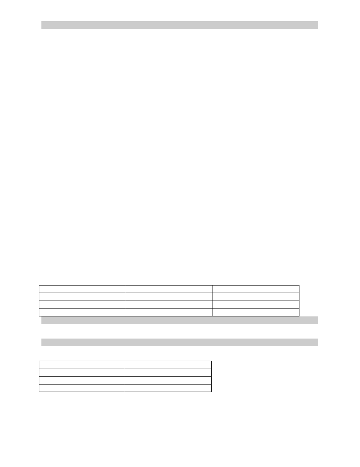
3.3.1 NETWORK / CONTROL Card
The NETWORK / CONTROL card allows
users to connect to the device cards from
an SSH or telnet session over an IP
network, and remote access to the
administration functions.
The NETWORK / CONTROL card
replaces the CONTROL card from the
CS3200, and is located in the far right slot
of the system chassis. Only one card is
required in an SCS3230.
The NETWORK / CONTROL card
includes one TERM connector for a local
Console; one 10/100 NET connector for a
TCP/IP network interface, and four
CHANNEL EXTENDER ports. The
Channel Extender ports are connected by
RJ45 cables to one to four CHANNEL
EXTENDER cards, which are an
extension of the NETWORK card's
operation.
The NETWORK / CONTROL card
supports up to sixteen simultaneous user
telnet connections and one administrator connection to the same IP address. The network card
must be connected to a network that uses TCP/IP.
15.00.038 - 19 - May 2002
Page 20

ConsoleServer 3200 System Lightwave Communications
3.3.2 CHANNEL EXTENDER Cards
CHANNEL EXTENDER cards are used to extend the NETWORK functionality of the
NETWORK / CONTROL card, providing network access to the DEVICE ports in the system.
The Channel Extenders provide additional circuits allowing more simultaneous network
sessions, up to the system capacity of 16 device sessions. Channel Extenders are installed in
slots B, C, D, and slot E, replacing the N ETWORK cards and the TERMINAL cards in a 3200
system.
The SCS3230 is normally configured with four CHANNEL EXTENDERS, but may have any
combination of CHANNEL EXTENDER cards and TERMINAL cards, as required for your
application.
Note: At least one Channe l Extender card is required if any DEVICE access is required using
your IP Network.
CHANNEL EXTENDER cards connect to the NETWORK / CONTROL card using a short RJ45
cable. Each CHANNEL EXTENDER provides up to four (4) simultaneous sessions for DEVICE
port access over the IP Network connection.
3.3.3 TERMINAL Cards
The TERMINAL card provides a point of connection for a conventional RS-232 terminal or a
computer running a terminal emulation program. Users connected through a TERMINAL card
may connect to any of the device cards in the system, provided that their user profile has
access rights for the port. There are four ports per terminal card. Each port‘s parameters are set
up independently from the other ports. All parameters are set up through the system
administrator port. There is no access to the administration functions through the terminal card.
The SCS3230 may have up to 3 Terminal cards, depending on system requirements. In some
applications, the existing Terminal Card may be required for local serial connection to one of the
Device Ports. The existing Terminal Card is compatible and may be used, however the use of
each Terminal Card(s) reduces the number of simultaneous Network connections (by 4
sessions) that may be made over the new 10/100 N etwork port on the Network Control Card.
The 3200 Terminal cards offer configurable port parameters (baud rate, DTE/DCE, etc.), unlike
the fixed parameters of the TERM (Console) port on the NETWORK / CONTROL card.
The SCS3230 requires version 4.00 (or higher) of the Terminal Card binary firmware (fterm.bin).
This is not specific to 3230, and has been available for some time. Firmware updates are
downloadable from the Lightwave FTP site (ftp://ftp.lightwavecom.com).
3.3.4 3200 Network Cards
The earlier 3200 Network card (10baseT) is not supported by the 3230 Network / Control Card.
It will not function if installed.
Rev. A - 20 - www.lightwavecom.com
Page 21

A Lantronix Company SCS3230 System Administrator's Guide
3.3.5 3200 10/100 Network Cards
The earlier 3200 10/100 Network card is not supported by the 3230 Network / Control Card.
It will not fun ction if installed.
3.3.6 Modem Card
The Modem Card is used primarily in the Console Server 3200 systems, however, it does not
provide or support any of the "secure" features of the SCS3230 system. It is not secure in the
sense that the modem circuitry is not subject to the encryption used for secure SSH
transactions, a primary reason for updating to the SCS3230. For this reason, the use of the
modem may be limited, or the modem may simply be disabled or removed, depending on your
site's application.
The modem card allows non-secure dial-in access to the SCS3230 and the servers attached to
its device ports. The modem card supports baud rates up to 38.4 kbps, and will auto-detect the
actual connection speed. Only one user at a time may access through the modem card, and
only one modem card may be installed per unit. The system administration functions may not
be accessed from the modem card.
15.00.038 - 21 - May 2002
Page 22

ConsoleServer 3200 System Lightwave Communications
4: Installation Instructions
Two options for your installation exist:
• you are either UPGRADING a CS3200 system to be an SCS3230 system, or
• you are installing a NEW SCS3230 system.
For simplicity, we will refer to a ConsoleServer 3200 system with the NETWORK/CONTROL
card installed as a SCS3220 system. In either case above, you will use THIS GUIDE for
administering the SCS3230 features and options, while referring to the ConsoleServer 3200
manual for a majority of the hardware installation instructions.
• When you purchase a CS3200 chassis, you will get the CS3200 manual (PN 15.00.017).
• When you purchase a SCS3230 NETWORK/CONTROL card, you will get the SCS3230
System Administrator's Guide (this manual, PN 15.00.038).
NOTE: The majority of this System Administrator's Guide is intended for the administration and
setup of the system, when using the SCS3230 kit. The hardware of the ConsoleServer 3200
may have been previously installed and is being upgraded at this time, or the system may be
installed as brand new installation.
Many hardware installation details are discussed in the ConsoleServer 3200 System Manual .
Not all are repeated in this manual.
4.1 Items in a SCS3230 Kit
The SCS3230 'kit' includes all of the cards and cables required to upgrade a CS3200 to the
SCS3230.
PN 500.000.0010 - 10/100 BT SECURE 3230 CARD KIT
includes:
- (1) 500.000.0014 -- 10/100 BT CNTL/NTWK Card
- (4) 500.000.0012 -- 3200 CHANNEL EXTENDER Card
- (4) 200.0161 -- CAT5 Cable, 24 inch long
This SCS3230 guide, PN 15.00.038 is included with each PN 500.000.0014 card.
Additional adapters and cables may also be included in the shipping container if ordered.
Orders with a large number of cables and adapters are usually shipped in separate containers.
If you are updating a CS3200 system, you may want to save your existing database from the
CS3200 and copy it into the SCS3230. To do so, you will use Backup to save the database,
and then Restore to copy it into the SCS3230's memory.
Rev. A - 22 - www.lightwavecom.com
Page 23

A Lantronix Company SCS3230 System Administrator's Guide
4.2 Move Database from your CS3200 to SCS3230
The SCS3230 is designed to work with the Backup and Restore options found in the CS3200
product. Y ou can transfer your database from the CS3200 to the SCS3230. To accomplish this,
you must save the Backup the system database to a local PC, and then after upgrading the
hardware, you can then upload the saved information.
If you do not use Backup and Restore, you will have to re-program the system with port and
user information.
This section assumes some existing familiarity with the administration methods (logging in,
using the TERM port, etc.) of the CS3200 system, much of which will be similar with the
SCS3230 system.
4.2.1 Backup Procedure of your CS3200 System
Before shutting down the CS3200 System, you should backup the existing user database. This
is a normal CS3200 operation, as described in the 3200 documentation.
1. Log in as the sys admin on Control card port A on the CS3200's CONTROL card.
2. Make sure that there are no users logged in to the ConsoleServer 3200. If there are
any, have them log out or force them off the system using the FORCELOGOUT command.
3. In the communications program, begin the text file capture. Name the text file as
something that will indicate that it is the ConsoleServer 3200 parameters backup file, not
just a plain text file (i.e., 3200.bak and not 3200.txt).
4. Type the command BACKUP at the sys admin> prompt and press <ENTER>. Text will
be outputted to the screen; this text is equivalent to the binary data stored in the
ConsoleServer 3200's non-volatile memory. Wait several minutes while the
ConsoleServer searches memory for all non-zero records (unused records are skipped
in the backup).
5. After the sys admin> prompt returns, end the text file capture in the communications
program.
6. Open the text file with a text editor (such as Window's Notepad text editor, or StarOffice,
etc.).
7. Remove any text after but not including the line $BACKUP COMPLETE. DO NOT EDIT
ANY OF THE TEXT ABOVE THIS LINE! It is not necessary to remove the text after
$BACKUP COMPLETE, but it reduces the download time for the file during the RESTORE
process.
4.2.2 Restore Procedure
After the SCS3230 sy stem is operational, you can transfer your CS3200 database into the
system using the RESTORE option. After your database is saved in the SCS3230 system, you
can backup and restore the SCS3230's user database using Backup and Restore.
1. Log in as the sys admin on TERM port on the NETWORK / CONTROL card.
2. Make sure that there are no users logged in to the SCS3230. If any users are currently
logged on, have them log out or force them off the system by using the FORCELOGOUT
command.
15.00.038 - 23 - May 2002
Page 24

ConsoleServer 3200 System Lightwave Communications
3. At the sys admin> prompt, type RESTORE and press <ENTER>. The SCS3230 will
prompt for confirmation to proceed with the parameter restore process. Type YES and
press <ENTER> to proceed. The system will ask for a second confirmation to proceed.
Type YES and <ENTER> to start the parameter restore process. After the second
confirmation, there is no text echoed to the screen indicating that the restore process is
proceeding.
4. Using the communications program, send the text file containing the backup records to
the SCS3230. Be sure to use text mode when transferring the file. The file download
should not take too much time; less than a minute is typical at 38.4K baud. After the
download is complete, the SCS3230 will re-zero all unused records. If a problem is
encountered during the text file transfer, the SCS3230 will abort the restore process and
return to the sys admin> prompt.
5. Once all unused records have been re-zeroed, the SCS3230 will reboot. Allow the
complete memory check to proceed; after it is done, log in as the sys admi n at the
LCI3200> prompt.
6. The ConsoleServer is restored to its previous settings and is ready for use. Check that
all user, terminal, device, and other parameters are correct and acceptable.
4.2.3 To RESTORE from a 3200 to a 3230
Use a terminal emulation software on a PC connected to the sysadmin port of a 3200. Ensure
that software flow control (XON/XOFF) is turned on for the software.
1. Implement a capture to file.
2. type “backup”.
3. Wait until you see “$BACKUP COMPLETE”
4. edit the backup file and remove any information before the line which starts 0,… This is
probably the first line. Also remove the couple of lines that say $BACKUP COMPLETE. After
the backup there will be some extraneous information, this needs to be removed.
Copy the file to the 3230. This can be accomplished using pscp or scp
Log in to the 3230 and establish yourself as root.
Cd to /lci/bin
Step 1) Type ‘restore “file name” yes’
“file name” is the name of the file you just copied.
The last yes is needed if you want to be told what passwords the system is inserting for this
user. If you do not want to see the passwords, do not type anything.
Unless there is an issue, you will observe users being added to the system and any changes
that take place to the user name or password. If you receive a message about record number
being incorrect, the file is either corrupt from flow control or you have not edited out the
extraneous information that is in the file from doing the backup.
If the service multidrop is running you will be asked to stop it and told how to do so ‘type
“service multidrop stop”’. Goto step 1.
Rev. A - 24 - www.lightwavecom.com
Page 25

A Lantronix Company SCS3230 System Administrator's Guide
4.2.4 LCI Update
There are four binary (.bin) files in the /lci/bin directory of the Network/Control card that may be
needed to update existing 3200 cards for use with the new Network/Control card's firmware:
- fterm.bin
- rterm.bin
- fdevice.bin
- rdevice.bin
These files are stored on the Network/Control Card in the /lci/bin directory on the card. The files
may also be downloaded from the Lightwave FTP site (ftp://ftp.lightwavecom.com). The
customer will use the lciupdate program to install these updates, however, they do not need to
transfer the binary files from an external computer to the 3200 - they should just direct
lciupdate to use the /lci/bin path.
It is not necessary to update the Device or Terminal cards before assembling the system,
however, before the system is put into service, the cards should be updated.
To Update a Card or Cards
From the 3230 bash shell, type the following.
[If you are in the sysadmin shell on a 3230, type ‘exit’ to get to the 3230 bash shell.]
• Establish yourself as super user
• Type ‘service multidrop stop’
• Type ‘ps –ax’ and look for any processes that contain the title multdrop.
• If any multidrop processes exist, type ‘killall multidrop’. Type ps-ax and again look for
any multidrop processes. If there are any, type ‘kill –9 “the number in the farthest left
column on the same line as the process”’, do this for all multidrop processes.
• Type lsmod and look for mdser. If mdser is not present type insmod mdser.
• If you wish to change the card binary file (*.bin) stored on the SCS3230, copy the update
file (filename.bin) to the 3230 and place in the “/lci/bin” directory.
• Type ‘/lci/bin/lci_update “[card letter][processor number]” file’. Where file is the name of
the file you for the slot you are updating. For instance you would probably type
• /lci/bin/lci_update b1 fterm.bin for terminal cards (the file name may be different and b
could be b,c,d,e)
• /lci/bin/lci_update h1 fdevice.bin for device cards (the file name may be different and h
could be h,I,j,k,l,m,n,o)
• The processor number is relevant to multiprocessor cards. You will be informed if it is
anything other than one.
15.00.038 - 25 - May 2002
Page 26

ConsoleServer 3200 System Lightwave Communications
4.3 Connecting to the TERM Port
The cable kit P/N 200.0135 contains the necessary adapters to interface the system TERM port
on the NETWORK / CONTROL card to a laptop or a terminal. Using the adapters in the kit,
follow the steps outlined below.
The communications settings for the system administrator port (TERM) are fixed at 9600 baud,
one stop bit, no parity, eight data bits, and DCE (9600 8N1 DCE).
NOTE: The administration functions may also be reached via telnet. However, it is first
necessary to configure the network ports through the direct serial connection.
1. Turn on power to the terminal or computer. If using a computer, start the desired
communication program. The terminal or communications program used must
be in VT100 emulation mode. Note that the VT100 functions keys are not always
mapped to the terminal or computer function keys; consult the appropriate
documentation for further information.
2. Ensure that the communications settings of your Terminal are correct.
3. Locate the serial port on the terminal or computer and determine what type of
connector is used. The cable kit included with the SCS3230 contains each of the
following: one RJ45 serial cable, an RJ45 to male DB9 adapter, an RJ45 to
female DB9 adapter, an RJ45 to male DB25 adapter, and an RJ45 to female
DB25 adapter. Select the appropriate adapter for the serial port on the terminal
or computer.
4. Firmly seat the adapter in the serial port. Screw down the adapter to secure it to
the serial port.
5. Insert one end of the serial cable into the adapter until a click is heard. I nsert the
other end of the serial cable into TERM port of the NETWORK / CONTROL card,
again until a click is heard.
6. Press <ENTER> on the keyboard. The login> (using Telnet) or login as: >
(using SSH) prompt should appear. If not, check that the SCS3230 is connected
to the appropriate power outlet, the power switch is on, the cards are firmly
seated, and that all cable connections are secure. If "garbage" characters
appear on the screen, check that the communications settings are correct.
7. The system administrator may now login to the system.
Rev. A - 26 - www.lightwavecom.com
Page 27

A Lantronix Company SCS3230 System Administrator's Guide
5: Connecting Equipment to the SCS3230
When connecting devices to the SCS3230, be sure to use Lightwave Communications
cables and adapters to ensure the proper transmission of data signals. If a device has
an RJ45 serial port, use the manufacturer's cable included with the equipment to
convert the RJ45 serial connector to a DB9 or DB25 connector, and then use a
Lightwave Communications adapter to convert back to RJ45 to attach to the device
port. Directly connecting the RJ45 port on the SCS3230 to the RJ45 port on a thirdparty device may not allow for the proper transmission of data signals.
SCS3230 serial port default settings
Port Type Baud Rate Data Bits Parity Stop Bits Port Configuration
TERM 9600 (fixed) 8 None 1 DCE
Terminal 38400 8 None 1 DCE
Device 9600 8 None 1 DCE
5.1 Terminal Card
Terminal Card typical adapters and port configuration:
System Type Adapter Part Number Port Configuration
Wyse 50 / 60 200.0066 DCE
DEC VT330, PC (25pin) 200.0067 DCE
PC (9pin) 200.0070 DCE
Materials:
• SCS3230 terminal port
• terminal or computer with RS-232 serial port
• RJ45-terminated Cat 5 cable (standard LAN cable)
• Lightwave adapter for terminal serial port
1. Attach the Lightwave adapter to the terminal or computer serial port.
2. Connect the Cat 5 cable to the adapter. Connect the other end to the SCS3230
terminal port.
3. Turn on the terminal or start the computer’s communication program. Make sure that
the communication parameters of the terminal or computer match those of the terminal
port.
15.00.038 - 27 - May 2002
Page 28

ConsoleServer 3200 System Lightwave Communications
5.2 NETWORK / CONTROL Card
The network port of the NETWORK / CONTROL card runs at 10/100 Mbits, half-duplex,
with auto-negotiation. The device used to connect the ConsoleServer to the network
(i.e., a hub or sw itch) must support this configuration.
Materials:
• SCS3230 network port
• network point-of-connection (i.e., a switch or hub)
• RJ45-terminated Cat 5 cable (standard LAN cable)
1. Configure the ConsoleServer network parameters to the desired values as
outlined in section 6.5.
2. Configure the network point-of-connection. It must be manually set to 10 Mbits, halfduplex, with no auto -negotiation.
3. Connect the ConsoleServer network port to the network using a standard LAN cable.
4. Check the status lights at the network end of the connection. It should indicate a good
link. Try reaching the IP address assigned to the ConsoleServer by using PING or
TELNET. If there is a problem, check the network configuration on both ends.
5.3 Modem Card
Materials:
• SCS3230 modem port
• Analog telephone line (POTS)
• RJ11 modular telephone cable
1. Locate the modular jack for the telephone line to be used. Select a telephone
cable with sufficient length to reach between the jack and the ConsoleServer.
2. Connect one end of the telephone cable to the jack. Connect the other end to
the ConsoleServer modem port.
3. Make sure the ConsoleServer is powered. Dial the telephone number of the line
connected to the ConsoleServer. The modem should automatically answer. If
not, check the telephone line and connections.
Rev. A - 28 - www.lightwavecom.com
Page 29
A Lantronix Company SCS3230 System Administrator's Guide
5.4 Device Card
NOTE: DEVICE Cards MUST be updated to Version 4.03 (or higher) firmware for SCS3230
The SCS3230 is designed so that the default device port communications settings will match
the communications settings of most Sun® server and workstation console ports (9600 baud, 8
data bits, no parity, one stop bit). Other equipment types (i.e., Cisco®) frequently use similar
communications settings; check the manuals included with the equipment for the correct
settings. The table below lists the default serial port communications settings for the SCS3230.
Sections 6.3 and 6.4 outline the commands for changing the terminal and device port
communications settings.
The following tables list the adapter part number and port configuration for some common
equipment types that may be connected to the SCS3230. Note that in some cases, an
additional cable or adapter is included with the equipment to convert a proprietary pinout to an
EIA-standard pinout. Also, note that it is not possible to connect the RJ45 serial port of the
ConsoleServer directly to the RJ45 serial port of any third-party equipment. Sun Netra
servers, Cisco switches, and other similar devices require a special adapter or cable to connect
to the ConsoleServer. The adapter or cable is usually provided by the manufacturer of the
equipment (e.g., Sun), or may need to be created by the user. The adapters and cables from
the equipment manufacturer are usually designed to interface directly to a terminal, so the
ConsoleServer device port must be configured as DTE rather than its default value of DCE.
Lightwave Communications has pre-made adapters and kits for some common equipment
types; contact Lightwave for information regarding your specific application.
Note: Some adapters are also available in quantity packs, and may be shipped under a different
part number. Quantity packs are "299.xxxx" compared to "200.xxxx".
Device Card typical adapters and 3200 port configuration:
System Type Adapter Part Number Port Configuration
SUN 200.0066 DCE
HP, SGI, PC (9pin) 200.0070 DCE
PC (25pin) 200.0067 DCE
Sun Netra t1/Cisco 200.0225 DCE
RJ45 to RJ45 Cables:
Part Number Length
200.0062 2m
200.0063 5m
200.0064 10m
200.0065 15m
15.00.038 - 29 - May 2002
Page 30

ConsoleServer 3200 System Lightwave Communications
Standard DB9 or DB25 installation:
Materials:
• SCS3230 device port
• device with RS-232-C serial console port
• RJ45-terminated Cat 5 cable (standard LAN cable)
• Lightwave adapter for serial console port
1. Attach the Lightwave adapter to the serial console port.
2. Connect the Cat 5 cable to the adapter. Connect the other end to the SCS3230 device
port.
3. Check that the device port and serial console port communications parameters match,
and synchronize them if they do not match.
Sun® Netra t1 installation:
Materials:
1. Connect a Cat 5 cable to the console port of the Netra. Connect the other end to the
end of the ConsoleServer/Netra adapter (P/N 200.0225) marked “to Netra”.
2. Connect another Cat 5 cable between the adapter end marked “ConsoleServer” and the
ConsoleServer device port.
3. Check that the device port and serial console port communications parameters match,
and synchronize them if they do not match.
Rev. A - 30 - www.lightwavecom.com
Page 31

A Lantronix Company SCS3230 System Administrator's Guide
ConsoleServer 3200 Adapter Quick Checklis
t
ble
-RJ45 Cable
RJ45-RJ45 Cable
to Switch
Sys
AdminTermina
l
pters are available
Call for inform
ation
abl
e
Control CardPort
“A”
Rj45 Connecto
r
Depending on
Sys
AdminTerminal I/O po
rt, ada
pterwill be one of following:200.0066 RJ45-DB25MOR200.0067 RJ45-DB25FOR200.0069 RJ45-DB9MOR200.0070 RJ45-DB9F
135
DTE
RJ45-RJ45 Cable
DCE
002
5
RJ4 5-RJ4 5 C
N ote: Other ada
from Lightwave.
Inclu ded in cable kit 200.0
and availability.
ConsoleServer 3200
.
PORT
DCE
CONFIG
DTE
DCE
DTE
DCE
DTE
DTE
DTE
RJ45 Connection
RJ 45-RJ4 5 Ca
RJ45-RJ45 Cable
O R
RJ45 -RJ4 5 Cable
Adapter
200.0067
DB25-RJ45
SGI Supplied
Te rminal Ca ble
Adapter
200.0070
DB9-RJ45
RJ45 -RJ4 5 Cable
Adapter
DB25-RJ45
RJ45-RJ45 Cable
RJ45-RJ45 Cable
Adapter
200.0066
DB25-RJ45
O R
Adapter
200.0067
DB25-RJ45
Sun Supplied
Te rminal Ca ble
200.0066
200.0225
RJ45-RJ 45 Cable
Adapter
200.0100
MMJ-DB25
Te rminal Ca ble
DEC Supplied
RJ45
Adapter
DB25-RJ45
Termina l Cable
Adapter
200.0067
IBM Supplie d
200.0067
DB25-RJ45
Termina l Cabl e
Cisco Supplied
200.
RJ4 5-RJ45 Cable
SGI
HP9000
(Origin,O2,
Octane, Onyx2)
Sun
Netra
RJ45
DEC
RS6000
Cisco
Cisco
w/RJ45
Router/Hub
15.00.038 - 31 - May 2002
Page 32

ConsoleServer 3200 System Lightwave Communications
$
%
&
'
1HWZRUN6ORWV
%&'(
SWITCH
SWITCH
A
B
C
D
B B B B B B B B
D D D D D D
Caution! Replace with same type and rating fuse.
100-240V ~, 1A, 50/60 Hz
T 4A, 250 VAC
MODEM
CHANNEL
EXTENDER
CHANNEL
CHANNEL
EXTENDER EXTENDER
T ERMINAL
Fig. 3 General layout showing DEVICE port numbering.
DEVICE
NETWORK/
CONTROL
10/100
T
E
R
M
C
H
A
N
N
E
L
E
X
T
E
N
D
E
R
S
N
E
T
DEVICE DEVICE DEVI CEDEVI CEDEVICEDEVICE
A A AA A A
C C CC C C
DEVICE
A A
C C
D D
%&'(
Rev. A - 32 - www.lightwavecom.com
Page 33

A Lantronix Company SCS3230 System Administrator's Guide
6: SCS3230 Setup Script and
System Administration
The SCS3230 uses a script file to assist in the initial setup and configuration of the 3230
system. The script is intended for the first time the unit is turned on, in order to get the system
'up and running' as quickly as possible.
Note: In some of the following screens, the term "3220" may be found in place of the "3230"
which is found in the actual screens of the SCS3230 system.
The following section outlines the administration functions and commands.
The administration functions and commands are designed to enable the administrator to
configure the SCS3230 to fit the needs of the system application. User IDs, devices, terminals
and access rights may be configured using the administration commands.
Many commands may be abbreviated to one extent or another, but some may not be
abbreviated at all. For example, the command VERSION may be abbreviated to VER, but
LCIUPDATE may not be abbreviated. See Appendix E for more information regarding
abbreviations.
15.00.038 - 33 - May 2002
Page 34

ConsoleServer 3200 System Lightwave Communications
NOTE: <ESC> <ESC> or <CTRL>+C will cancel an operation and return to the administrator
prompt. Pressing <CTRL>+R at the LCI3200> or sys admin> prompt will discard the
characters on the current command line, and retype the last command used; <ENTER> must still
be pressed to execute the command. Pressing <CTRL>+U at either prompt erases the current
command line back to the prompt.
6.1 Power-up Sequence and
Basic Use of the Administrator Functions
NOTE: When the system is first turned on, it may take as long as 90 seconds before the front
panel display will show any activity, and before the system will 'wake up'. Total boot-up time is
generally about 3 minutes .
When the SCS3230 is first installed and powered up, it must be configured through the serial
terminal port. Connect the terminal port to a terminal device or computer using a terminal
emulation program. After the network interface has been configured, the administration login
may also be reached via telnet. All the functions available from a local serial connection (with
the exception of BACKUP and RESTORE) are also available through telnet by connecting to port
5000 of a ConsoleServer’s network IP address.
The serial terminal will display the following text at power-up:
ConsoleServer3200 Boot V1.76
Copyright 2000 by Lightwave Communications, Inc. All rights reserved.
Identify Flash
Flash ID OK
Verifying Flash Image
Starting system
Lightwave Communications, Inc. ConsoleServer3200
Please wait...system initializing
Checking non-volatile memory...
2048
Start checking and reading stored data
Reading User Start up .........
LCI3200>>
The power -on self-test may be skipped by pressing <ESC> <ESC> or <CTRL>+C, but
the SCS3230 should be allowed to complete the POST if possible (this check usually
takes about three minutes). This information is not available on a network connection,
as it is not possible to connect to the ConsoleServer via telnet until the power-on selftest is complete. At the completion of the power-up sequence, the administrator is
logged out, as indicated by the LCI3200>> prompt. Some commands may be used
from this prompt, but most are available only when logged in.
NOTE: The administrator may define the system prompt using the PROMPT command (see
section 6.11), but the system default prompt (LCI3200>>) is used in this guide for clarity.
Rev. A - 34 - www.lightwavecom.com
Page 35

A Lantronix Company SCS3230 System Administrator's Guide
6.1.1 Logging In, Serial Connection
LCI3200>>login
Please enter password: ****
sys admin>>
To log in on the ConsoleServer through a local serial connection, type LOGIN at the
LCI3200>> prompt. The system returns the prompt Please enter password:. The
default administrator password is PASS. The ConsoleServer will only echo stars when the
password is entered. If the password is correct, the prompt will change to sys admin>>.
6.1.2 Logging In, Network Connection
UNIX_MACHINE# telnet 172.16.1.200 5000
Connecting to 172.16.1.200 port 5000...
Escape sequence is ^]
Welcome to the ConsoleServer3200 SysAdmin
LCI3200>>login
Please enter password: ****
sys admin>>
To log in on the ConsoleServer through a network connection, the network interface for the
ConsoleServer first must be configured through the serial terminal. Once the network interface
is configured and functioning, telnet to port 5000 of the IP address assigned to the
ConsoleServer. The ConsoleServer will display a welcome message and the LCI3200>>
prompt. At the prompt, type LOGIN. The system will only prompt for the password. At the
Please enter password: prompt, enter the administration password. The default
administrator password is PASS.
If the password is correct, the prompt will change to sys admin>>.
15.00.038 - 35 - May 2002
Page 36

ConsoleServer 3200 System Lightwave Communications
6.1.3 Logging Out
To log out from an administration session, enter the command LOGOUT or LOGOFF. If logging
out from a network session, the ConsoleServer will disconnect the telnet session. If logging out
from a direct serial session, the ConsoleServer will return to the LCI3200>> prompt.
Rev. A - 36 - www.lightwavecom.com
Page 37

A Lantronix Company SCS3230 System Administrator's Guide
6.1.4 System Help (Command List)
To access the help screens, type <F1> H, ?, or HELP to display the help page, once logged in.
The HELP screens offer a Sys Admin Command List.
HELP SCREEN
sys admin>>?
ConsoleServer 3230 Sys Admin Command List
[] - optional <> - parameter must be specified | - OR
abbreviations - Display list of command abbreviations
adduser [new user id] - Add a new user
break <terminal channel> - Break connection
connections [/monitor] - Display list of current connections
(/MONITOR will auto-refresh)
deleteuser [user id|/n] - Delete a user by user id or number
devices - Display device settings
devices [n|device name] - Change settings (n can be 1 to 32)
edituser [user id] - Edit a user's settings
forcelogout <terminal channel> - Force a user off the system
forcelogout sysadmin - Logout sys admin on a network connection
info <slot letter> - Report miscellaneous information
linesperpage [n] - Display/set number of lines before pause
(n can be 0 to 99, 0 disables)
listcards - Display list of installed cards
listdevices - Display list of device names
listusers [user id|/all] - Display list of users
exit - Exit sysadmin shell
modem [/default] - Display/set modem init string
/DEFAULT will set init string to default
Press <CR> to continue
modemtimeout [t] - Display/set timeout for modem calls
(t can be 0 to 30 minutes, 0 disables)
powerstatus - Display status of power supplies
prompt [/clear|/default] - Set/clear system prompt for logged-out state
or set prompt to factory default
telnettimeout [t] - Display/set timeout for telnet sessions
(t can be 0 to 30 minutes, 0 disables)
terminals - Display terminal settings
terminals [n] - Change settings (n can be 1 to 17)
timeout [t] - Display/set timeout on sys admin login
(t can be 0 to 30 minutes, 0 disables)
version [/all|slot letter] - Report software version information
(/ALL will return versions for all cards)
sys admin>>
15.00.038 - 37 - May 2002
Page 38

ConsoleServer 3200 System Lightwave Communications
6.1.5 Abbreviations
A listing of abbreviations for the administrator commands is also available when
connected to the administrator port.
sys admin>>abbreviations
ConsoleServer 3230 Sys Admin Command Abreviations List
abbreviations - a
adduser - addu
au
break - (no abbreviation)
connections - c
deleteuser - deleteu
devices - dev
edituser - editu
eu
forcelogout - (no abbreviation)
help - h, ?
info - (no abbreviation)
linesperpage - linespp
lines
lpp
listcards - listc
lc
listdevices - listd
ld
listusers - listu
lu
Press <CR> to continue
exit - (no abbreviation)
modem - (no abbreviation)
modemtimeout - modemt
mt
powerstatus - po
ps
prompt - pr
telnettimeout - telnett
tt
terminals - term
timeout - time
version - ver
sys admin>>
You must use the <CR> to go to the second page of the Abbreviations list. You cannot interrupt
it in the middle, only let it play out. THEN, you return to sys admin>.
sysadmin@SCS3230 /tmp$ h
Command User Description
-------- ---- -----------
SAVE root Save changes in RAM to Flash
changes root List changed files from factory settings
lciupdate root Download flash updates to terminal or device cards
poweroff root Power off the SCS3230
reboot root Reboot the SCS3230
restore root Restore pararmeters from a previous save
setup root Run the System Configuration script
sysadmin sysadmin/root Run the Sys Admin shell
timeout root Display/set timeouts for console or telnet logins
unsaved root List files changed since last SAVE
sysadmin@SCS3230 /tmp$ sysadmin
sys admin>>
Rev. A - 38 - www.lightwavecom.com
Page 39

A Lantronix Company SCS3230 System Administrator's Guide
6.2 Sys Admin vs. root access
The System Administrator (sys admin) has the ability to run the sysadmin functions of the
system. In order to run the Setup command, the System Administrator must change to the root
user. Below is a list of commands accessible by the different admin levels:
The Sys Admin must sign on, and then switch to root level (requires root password) so that they
may run the Setup command. The default root password is 'root'. This root password should be
changed as soon as the System Administrator has gained access to the system.
To Change the root-level password of the SCS3230, follow the steps below.
1. Log in as sysadmin (you see the bash prompt) = sysadmin@SCS3230 /tmp$
2. su to root level; you must enter the existing root password (default = root)
3. After password is accepted, notice root level = root@SCS3230 /var/tmp#
4. Use passwd to change root level password
5. After successful, 'authentication tokens updated ' message is displayed. You are
returned to the root level prompt = root@SCS3230 /var/tmp#
6. Use exit to leave root level (sysadmin@SCS3230 /tmp$)
7. Use logout to log out of the system
If you lose the root password, there is no 'back door' password or higher-level access. The
Flash memory device would have to be replaced in order to regain access to the system. Your
existing data on that Flash device would be inacessible.
Only the root level password has access to the SAVE feature which can invoke permanent
changes to the system's memory and features. Turn the system power off without using SAVE
will cause any system changes to be lost.
15.00.038 - 39 - May 2002
Page 40

ConsoleServer 3200 System Lightwave Communications
6.3 Setup Script
The System Administrator must switch to root level in order to access the Setup Script.
From the root command prompt, type setup to begin the setup script:
Follow the script prompts; use the arrows or 'Enter' to advance unless otherwise indicated.
Rev. A - 40 - www.lightwavecom.com
Page 41

A Lantronix Company SCS3230 System Administrator's Guide
Using the arrow keys, you may select from any of the following attributed to administer. The
script also provides 'hints' along the way. You may also 'exit' using the Done command. Using
the 'enter' key to advance, you will step through a majority of the Setup script.
6.3.1 Hostname and IP Address
Use the arrow keys to advance; or in some cases, simply press 'enter'.
The existing HOSTNAME information is displayed in the 'Answer' field.
15.00.038 - 41 - May 2002
Page 42

ConsoleServer 3200 System Lightwave Communications
Type in your HOSTNAME information in the Answer field. It may be up to 24 characters long; it i
After entering your Hostname, the system advances to the IP Address setting.
Enter your IP information, in dot-quad format. Select Next to proceed.
Rev. A - 42 - www.lightwavecom.com
Page 43

A Lantronix Company SCS3230 System Administrator's Guide
Next, enter your Network Mask information, in dot-quad format. Select Next to proceed.
Then, enter your gateway information. Select Next to proceed.
15.00.038 - 43 - May 2002
Page 44

ConsoleServer 3200 System Lightwave Communications
You are then returned to the Script's menu. You may continue the script by pressing 'enter' to
advance, or select another option.
6.3.2 Timezone (Clock)
You must select a Timezone value for the SCS3230's clock. The SCS3230 uses the universal
time system
Rev. A - 44 - www.lightwavecom.com
Page 45

A Lantronix Company SCS3230 System Administrator's Guide
Using the up and down arrows, select an appropriate Time Zone parameter. To go up one level
in the Time Zone menu, move to the ".." prompt at the top of the list. Press 'enter' to select
your value.
Once completing the Timezone field, you are returned to the Script's menu.
15.00.038 - 45 - May 2002
Page 46

ConsoleServer 3200 System Lightwave Communications
6.3.3 Configure DNS
Select 'Next' to advance in the DNS (Directory Name Server) menu.
Rev. A - 46 - www.lightwavecom.com
Page 47

A Lantronix Company SCS3230 System Administrator's Guide
Fill in the IP address information for your Primary Nameserver.
Note: If you start to fill in this parameter, but cannot complete the value at this time, you must
enter some dot-quad address in order to leave this prompt. A value of '10.0.0.1' may be suitable
in this instance.
Enter your Secondary Nameserver information, if appplicable. Press Next to advance.
15.00.038 - 47 - May 2002
Page 48

ConsoleServer 3200 System Lightwave Communications
Enter your Tertiary Namese rver information, if applicable.
Press Next to advance to the configuration for Hosts.
6.3.4 Hosts
The parameters for HOSTS is a bit different than other screens. Here, you will edit the data.
Rev. A - 48 - www.lightwavecom.com
Page 49

A Lantronix Company SCS3230 System Administrator's Guide
The system has started an 'edit' routine which you must 'exit' by using the ESC key to end the
edit mode, and get to the 'Next' prompt
You are then returned to the Script menu.
6.3.5 Services
You can now enable or disable several Services of the SCS3230.
15.00.038 - 49 - May 2002
Page 50

ConsoleServer 3200 System Lightwave Communications
Choose Yes or No, by using your arrow keys. Press Next to advance.
6.3.6 Syslog
Rev. A - 50 - www.lightwavecom.com
Page 51

A Lantronix Company SCS3230 System Administrator's Guide
6.3.7 SSH Logins
SSH is the secure, and preferred method of accessing the system.
15.00.038 - 51 - May 2002
Page 52

ConsoleServer 3200 System Lightwave Communications
6.3.8 TELNET logins
6.3.9 NTP Daemon
You can enable or disable the NTP Daemon, if desired.
After setting the NTP Daemon, you are returned to the Script's Menu.
Rev. A - 52 - www.lightwavecom.com
Page 53

A Lantronix Company SCS3230 System Administrator's Guide
6.3.10 Configure the Firewall
You can configure the firewall, for security in your system.
Press Next to advance.
15.00.038 - 53 - May 2002
Page 54

ConsoleServer 3200 System Lightwave Communications
Enable the Firewall to see additional prompts. Choose No to end this step.
Rev. A - 54 - www.lightwavecom.com
Page 55

A Lantronix Company SCS3230 System Administrator's Guide
6.3.11 Firewall Reject Method
You can choose to Deny (ignore) connection attempts, or send back a 'Rejected' message.
6.3.12 Ping Attempts
15.00.038 - 55 - May 2002
Page 56

ConsoleServer 3200 System Lightwave Communications
After finishing the 'Invisible to Ping' prompt, you will be returned to the Script Menu. There are
no more script options to do. You may go back and re-do any prompts you wish, if necessary.
Rev. A - 56 - www.lightwavecom.com
Page 57

A Lantronix Company SCS3230 System Administrator's Guide
6.3.13 Confirm Changes
Selecting YES will 'commit' the changes to the System.
15.00.038 - 57 - May 2002
Page 58

ConsoleServer 3200 System Lightwave Communications
The System will run through the system configuration and make the appropriate changes. Note
that some commands may show a 'fail' which may be normal for that instance. A 'fail' message
may mean that a command was not previously running, and so the command to kill that
application 'failed' (because it wasn't running). However, if you review the operations at a later
time, you will probably see an 'OK' message for the same prompts and options.
THE VERY FIRST TIME the System is run, the Setup script will automatically undergo a reset
and reboot to save the features to the system.
6.3.14 SAVE Command
Every other operation of the Setup script file, the root-level system administrator will have to
execute the SAVE COMMAND in order to preserve the changed values.
Rev. A - 58 - www.lightwavecom.com
Page 59

A Lantronix Company SCS3230 System Administrator's Guide
7: Creating and Managing Users
7.1 Adding a User ID
The ADDUSER command creates user IDs and assigns initial privileges. The following
screen will be displayed when the command is used:
sys admin>>ADDUSER
Number of available user records: 200
Number of users defined: 0
Enter user id | USER ID >
Press <ENTER> after typing the user ID. The user name is not case -sensitive. The next prompt
asks for a password for the user ID. When the user logs in for the first time he will be asked for
this password. This password is case -sensitive and is pre-expired. The user must change the
password before accessing any of the SCS3230 device ports. The user password may be up to
10 alphanumeric characters long, and may not contain the “*” character. The SCS3230 will
echo only stars when the sys admin enters the password and confirmation
Enter case sensitive password | PASSWORD > ****
Re-enter case sensitive password | PASSWORD > ****
0-17 | MAX CONCURRENT LOGINS: 1>17
This parameter limits the number of simultaneous logins a user may have. The sys
admin may select between 0 and 17 concurrent logins. A user with 0 logins will have
connect and listen permissions defined, but cannot login to access anything until a
number of logins greater than 0 is defined.
Allowed devices example: 1-5,10 | DEVICES 0 > 1,5,7,8,30
Allowed listen devices example: 1-5,10 | DEVICES 0 > 1-32
The sys admin is now prompted to define the device ports that the user will be allowed
to access for direct connections and listening connections. If more than one port is to
be allowed, then the individual ports must be separated by a comma. A range of ports
may be specified using the dash (“ -“).
15.00.038 - 59 - May 2002
Page 60

ConsoleServer 3200 System Lightwave Communications
DEVICE
ABC
D
DEVICE
ABC
D
DEVICE
DEVICE
ABC
D
DEVICE
ABC
D
2122232425262728293031
32
5
A
6
B
7
C
8
D
DEVICE
9
A
10
B
11
C
12
D
13
A
14
B
15
C
16
D
17
18
19
20
DEVICE
DEVICE
1
A
2
B
3
C
4
D
Allowed devices determines which devices a user may select for direct access.
Allowed listen devices determines which devices a user may use listen access.
“Listening” is defined as being able to read from an existing device port connection
without write ability. This feature is useful for sharing information among multiple users
or for monitoring a user’s session with an attached device.
Fig. 4 Device Port Numbering
HELPFUL HINT: Make a diagram or spreadsheet of connections indicating connections
between devices and the SCS3230 device ports as numbered above.
The Allow user to clear device buffer (Y/N) | YES > option determines
whether a user may use the CLEAR command to delete all the data stored in a device
port FIFO buffer. The sys admin may want to inhibit this ability to preserve user
accountability when accessing attached devices. Users are allowed to clear buffers by
default. Pressing <ENTER> will allow the user to clear the buffer; typing NO and then
pressing <ENTER> at the prompt when defining a user ID will disallow the user from
clearing all device buffers.
The Clear screen after a command (Y/N) | YES > option determines if the
screen clears when most commands are executed. Disallowing this screen behavior
keeps the last few commands and responses on the terminal screen. The default value
for this option is YES. Pressing <ENTER> will accept the default value; typing NO and
then pressing <ENTER> disallows this screen behavior.
Rev. A - 60 - www.lightwavecom.com
Page 61

A Lantronix Company SCS3230 System Administrator's Guide
sys admin>>ADDUSER
Number of available user records: 200
Number of users defined: 0
Enter user id | USER ID > tom
Enter case sensitive password | PASSWORD > ****
Re-enter case sensitive password | PASSWORD > ****
0-17 | MAX CONCURRENT LOGINS: 1> 2
Allowed devices example: 1-5,10 | DEVICES 0 > 1-4
Allowed listen devices example: 1-5,10 | DEVICES 0 > 0
Allow user to clear device buffer (Y/N) | YES > n
Clear screen after a command (Y/N) | YES > n
Enter user id | USER ID >
Sys admin>>
The above procedure has defined one user. The SCS3230 will prom pt for the next user
ID to be defined. Repeat the set-up process until all users have been entered. To
return to the sys admin prompt, simply press <ENTER> at the USER ID> prompt. More
users may be added at any time by using the ADDUSER command. A maximum of 200
users may be defined.
7.2 Editing a User ID
sys admin>>EDITUSER TOM
Enter accepts present value
Enter case sensitive password | PASSWORD >
0-17 | MAX CONCURRENT LOGINS: 2>6
Allowed devices example: 1-5,10 | DEVICES 1-4 >
Allowed listen devices example: 1-5,10 | DEVICES 0 >
Allow user to clear device buffer (Y/N) | YES > n
Clear screen after a command (Y/N) | NO > n
sys admin>>
To edit or change parameters for a particular user after defining that user ID, use the
EDITUSER command. For example, if the user 'Tom' needed to have more concurrent
login capabilities, the sys admin would type EDITUSER TOM on the command line. As
each line comes up, change the settings and press <ENTER>, or press <ENTER> to
accept the current setting.
NOTE: When editing any group of parameters, pressing the <ENTER> key will accept
the current value and move to the next parameter in the list.
7.3 Listing User IDs
To list the users that have been defined, use the LISTUSERS command. When used
alone, the command will display all user ID’s. When a user ID is specified after the
command, the parameters for that user ID will be displayed. If the /ALL qualifier is
15.00.038 - 61 - May 2002
Page 62

ConsoleServer 3200 System Lightwave Communications
included after the LISTUSERS command, then the parameters for all users are
displayed.
sys admin>>LISTUSERS
1: User id > PETE
2: User id > KEVIN
3: User id > TONY
sys admin>>LISTUSERS /ALL
1: User id > PETE
Allowed devices > 1-32
Allowed listen devices > 1-32
Max logins > 17
Allow user to clear device buffer > YES
Clear screen after a command > YES
2: User id > KEVIN
Allowed devices > 1-32
Allowed listen devices > 1-32
Max logins > 17
Allow user to clear device buffer > YES
Clear screen after a command > YES
3: User id > TONY
Allowed devices > 1-32
Allowed devices > 1-32
Max logins > 17
Allow user to clear device buffer > YES
Clear screen after a command > YES
sys admin>>
Rev. A - 62 - www.lightwavecom.com
Page 63

A Lantronix Company SCS3230 System Administrator's Guide
7.4 Deleting a User ID
To delete a user, use the DELETEUSER command, followed by the user ID on the same
line. The LISTUSERS command will allow verification after deleting a user ID. The
following command sequence is an example of the use of DELETEUSER with
LISTUSERS:
sys admin>>DELETEUSER PETE
Delete user:pete Yes or No (N):y
sys admin>>listusers
2: User id > KEVIN
3: User id > TONY
sys admin>>
User IDs may also be deleted by their record number. As each user ID is created, it is assigned
a sequential record number. This number is associated with the user ID and will be displayed
using the LISTUSER command.
sys admin>> deleteuser /3
Delete user:tony Yes or No (N):y
sys admin>>
To delete a user ID using the record number, specify the number as a qualifier after the
DELETEUSER command in the form DELETEUSER /N, where N is the user record number.
7.5 Devices Command
Device port parameters must be defined by the sys admin using the DEVICES
command. If a single device port is to be changed, the port number must follow the
DEVICES command. If the DEVICES command is entered by itself, the configuration of
all device ports will be listed. To edit all possible device ports for a unit, enter the
command DEVICES /ALL .
Programmable elements include: device name, baud rate, stop bits, parity, data bits,
DCE/DTE, flow control and inhibit direct mode. Pressing <ENTER> accepts the
parameter as is. If changes need to be made, each parameter may be edited as it
comes up after each > prompt.
The device name may not contain the * character. If a name is entered with this
character, the administrator will be asked to re-enter the name.
15.00.038 - 63 - May 2002
Page 64

ConsoleServer 3200 System Lightwave Communications
Four baud rates are offered: 9600, 19200, 38400, and 57600. Most devices use 9600
as the console/admin port baud rate, so the device port defaults to this value. Check
the equipment documentation for the proper baud rate.
The format of the bit-wise transmission of data is determined by the stop bits, parity,
and data bits parameters. The default settings are 1 stop bit, no parity, and 8 data bits.
Check the equipment documentation for the proper settings.
Each device port may be separately configured as either DCE or DTE. The DCE setting
is used when connecting to a DTE device such as a computer. The DTE setting is used
when connecting to a DCE device such as a managed switch. The device ports are
configured as DCE by default.
The device port flow control setting determines the method of flow control. The two
most common settings are XON/XOFF (a.k.a. software) and RTS/CTS (a.k.a.
hardware). DTR/DSR is used very infrequently. The default setting for the device ports
is XON/XOFF. Check the equipment documentation for the correct flow control setting.
The INHIBIT DIRECT MODE setting allows the administrator to turn off port buffering
while a user is connected to the device and is in direct mode. The device port buffer still
collects data while not in direct mode when this setting is active. It may be desirable to
disable direct mode buffering so sensitive data is not viewable by other users, but alert
and panic messages from the attached device are still stored when nobody is
connected. This setting is disabled by default, so buffer data is collected both in and out
of direct mode.
sys admin>>terminal 1
Enter accepts present value
T1: 0=9600, 1=19200, 2=38400, 3=57600 | BAUD RATE: 9600>
T1: 0=1, 1=2 | STOP BITS: 1>
T1: 0=None, 1=Odd, 2=Even | PARITY: None>
T1: 0=8, 1=7, 2=6 | DATA BITS: 8>
T1: 0=DCE, 1=DTE | EQUIP PORT TYPE: DCE>
T1: 0=XON/OFF, 2=RTS/CTS | FLOW CONTROL: XON/XOFF>
Card installed, settings updated
sys admin>>
A list of device port names and their corresponding port number may be displayed by
using the LISTDEVICES command.
Rev. A - 64 - www.lightwavecom.com
Page 65

A Lantronix Company SCS3230 System Administrator's Guide
7.6 Terminals Command
The sys admin defines terminal port parameters using the TERMINALS command in a
manner similar to the DEVICES command. If the command is entered by itself, the
terminal settings will display. If the terminal port number is specified after the
command, then the settings for that terminal port may be altered. Programmable
elements include: device name, baud rate, stop bits, parity, data bits, DCE/DTE, and
flow control as in the example below.
sys admin>>TERMINALS 1
Enter accepts present value
T1: 0=9600, 1=19200, 2=38400, 3=57600 | BAUD RATE: 38400>
T1: 0=1, 1=2 | STOP BITS: 1>
T1: 0=None, 1=Odd, 2=Even | PARITY: None>
T1: 0=8, 1=7, 2=6 | DATA BITS: 8>
T1: 0=DCE, 1=DTE | EQUIP PORT TYPE: DTE>
T1: 0=XON/OFF, 1=DTR/DSR, 2=RTS/CTS | FLOW CONTROL: XON/XOFF>
Card installed, settings updated
sys admin>>
Terminal port connection location reference template:
7.7 Network Commands
The NETWORK command setup is changed, if compared to the CS3200 system.
The NETWORK or access ports in chassis slots B, C, D and E are connected to the
CONTROL/NETWORK card using CHANNEL EXTENDER cards. All chassis backplane
Network ports are accessed through the 10/100 IP network port on the CONTROL/NETWORK
card.
When used without qualifiers, the NETWORK command will display the network settings assigned
to each card slot. The IP address, subnet mask, default gateway, secondary route, and bootp
settings are displayed for each slot. These parameters are assigned to the slots rather than the
cards. If a network card is moved from one slot to another, it will have the parameters assigned
to its new slot rather than those previously assigned to it.
When used with the /ALL qualifier, the NETWORK command will allow the system administrator
to change the network parameters for all the card slots in order. The sys admin will be
prompted to enter the IP address, subnet mask, default gateway, secondary route, and bootp
settings for each card slot. If <ENTER> is pressed at the prompt, the value displayed in the
prompt will be used. After entering the parameters for each slot, the sys admin will be asked if
the new parameters should be used. If NO is entered (or just <ENTER> is pressed), then the
previously entered changes will be discarded and the system will move on to the next slot’s
parameters. If YES is entered, then the slot’s network parameters will update in control card
memory and the control card will send the new parameters immediately to the card in that slot.
15.00.038 - 65 - May 2002
Page 66

ConsoleServer 3200 System Lightwave Communications
If the card is a network card, it will immediately acquire the new network parameters and
disconnect all telnet sessions to that card. If a terminal card is in the slot, or if the slot is empty,
the network parameter update is refused, but the network parameters for that slot will be saved
to control card memory.
When the NETWORK command is used with a card slot letter as a command qualifier, it will
attempt to change the parameters only for that card slot. In all other aspects, the command
behaves the same as if the /ALL qualifier was used.
If a bootp server is present on the same network as the SCS3230 network card and bootp is
enabled on the network card, then the network card will use the IP address and subnet mask
assigned by the bootp server rather than those assigned by the sys admin.
Once a network card has been assigned an IP address either by a bootp server or by the sys
admin, then the ConsoleServer may be accessed by telnet. Connecting to the default telnet
port reaches the user login; connecting to port 5000 reaches the sys admin login.
7.8 Modem Command
The MODEM command allows manipulation of the modem card initialization string. When the
command is entered, the sys admin is prompted for the new initialization string. Typing a new
initialization string and pressing <ENTER> will create a new initialization string for the modem,
while just pressing <ENTER> will accept the current value. After pressing <ENTER>, the sys
admin is asked to confirm the changes to send the string to the modem. Typing YES and
<ENTER> will send the initialization string immediately to the modem card, while typing NO and
<ENTER> discards the entered initialization string and keeps the old string. If the modem card is
not currently installed, the settings are not sent, but are kept in control card memory. The
control card will send those settings in me mory when a modem card is installed.
sys admin>>MODEM
Enter accepts present value
Init string | > ATB2H0
Save changes and update modem card? Yes or No: No>yes
Modem card not installed in slot A, init string saved
Sys admin>MODEM /DEFAULT
Current modem init string is: ATB2H0
Set modem to factory default value of: ATH0S0=1
(write out YES) Yes or No: No>yes
Modem card not installed in slot A, init string saved
sys admin>>
The sys admin may also reset the initialization string to the default value by entering the
command with the default qualifier in the form MODEM /DEFAULT. When using the /DEFAULT
qualifier, the current initialization string is displayed, along with the factory default string. The
sys admin is asked to confirm the use of the default modem string; typing YES and <ENTER> will
send the default initialization string immediately to the modem card, while typing NO and
<ENTER> keeps the old modem string.
Rev. A - 66 - www.lightwavecom.com
Page 67

A Lantronix Company SCS3230 System Administrator's Guide
It is recommended that the default modem initialization string be used unless the application
requires that it be changed. The default initialization string is ATH0S0=1, which disconnects any
active phone connections when the initialization string is sent, and sets the modem to autoanswer on one ring.
7.9 Status Commands
There are six commands which allow the sys admin to check the status of the
SCS3230: CONNECTIONS, LISTCARDS, VERSION, INFO, POWERSTATUS and LOG.
7.9.1 CONNECTIONS Command
The sys admin may monitor the status of connections made through the terminal cards
by using the CONNECTIONS command. This command will display all the active
connections and the mode of those connections as follows:
sys admin>>CONNECTIONS
Terminal Connection List
01 KEVIN 01 SERVER ( Monitor mode )
02 00 ( Channel present )
03 00 ( Channel present )
04 00 ( Channel present )
05 00 ( Channel present )
06 00 ( Channel present )
07 00 ( Channel present )
08 00 ( Channel present )
09 00 ( Channel present )
10 00 ( Channel present )
11 00 ( Channel present )
12 00 ( Channel present )
13 00 ( Channel present )
14 00 ( Channel present )
15 00 ( Channel present )
16 00 ( Channel present )
17 <not installed>
sys admin>>
The above example shows that user KEVIN is logged in on terminal port 01, is
connected to device port 01 (which is named "Server" in the SCS3230), and is in
monitor mode. The list will display the user ID of any logged-in users, the device port to
which they are connected, the device name assigned to that port, and the mode of that
connection (see sections 7.8, 7.9, and 7.10 for an explanation of the various connection
modes). If the user is not connected to any device, they shall simply be listed as "User
Logged-In".
When used with the /MONITOR command line qualifier, the CONNECTIONS command
updates the connection list on screen every time a user logs in or out or changes login level
(i.e., goes into direct mode), rather than simply displaying the list once as occurs when the
15.00.038 - 67 - May 2002
Page 68

ConsoleServer 3200 System Lightwave Communications
CONNECTIONS command is used alone. (See section 6.8, Sys Admin Session Management
Commands).
The CONNECTIONS command will also tell the sys admin which terminal ports are
present (in the list, they are referred to as "channels"). If the port is not functioning (i.e.,
the card is not present or there is a fault with the individual port), the port will be listed
as "<not installed>". It will also list Telnet Active for an active Telnet session.
7.9.2 LISTCARDS Command
Sys admin>>LISTCARDS
Installed cards
Slot A : <card not installed>
Slot B : Terminal card installed
Slot C : Terminal card installed
Slot D : Terminal card installed
Slot E : Terminal card installed
Slot F : Switch card 1 installed
Slot G : Switch card 2 installed
Slot H : Device card installed
Slot I : Device card installed
Slot J : Device card installed
Slot K : Device card installed
Slot L : Device card installed
Slot M : Device card installed
Slot N : Device card installed
Slot O : Device card installed
sys admin>>
The LISTCARDS command will simply tell the sys admin which cards are plugged into
the SCS3230 chassis. It only lists the cards (by type) as present or not present, and
does not indicate whether the cards are functioning properly.
7.9.3 VERSION Command
sys admin>>VERSION /ALL
SCS3230
Slot B1: V2.15 10/01/99 Terminal Boot V1.62 (Sep 30 1999) (14:33:12)
Slot C1: V2.15n 10/01/99 Net Terminal Boot V1.62 (Sep 30 1999) (12:44:32)
Slot C2: V1.16 Build 7 09/29/99 Network Boot V1.62 (Sep 30 1999) (14:45:52)
Ethernet Address: 00-30-31-00-01-D5
Slot F1: V 1.03 Switch 1
Slot G1: V 1.03 Switch 2
Slot H1: V2.15 10/04/99 Device Boot V1.62 (Sep 30 1999) (14:40:51)
Slot P1: V2.12 Build 15 10/01/99 Control Boot V1.62 (Oct 01 1999) (11:13:06)
sys admin>>
By itself, the VERSION command lists the boot and flash software version for the control
card. The version information for a single card other than the control card may be
displayed by typing the card slot letter ID after the VERSION command. If the sys admin
Rev. A - 68 - www.lightwavecom.com
Page 69

A Lantronix Company SCS3230 System Administrator's Guide
desires to list the software version for all cards, he should type VERSION /ALL at the
command prompt. This will list the versions of the boot and flash software for all cards,
listed by card slot letter designation. Each network card will display two sets of software
versions: one set for the network portion of the card and one for the user terminal
portion, while all other cards will only return one set of version information.
7.9.4 INFO Command
sys admin>>INFO A
Slot A1: Modem: No Active Call Timeout = 1 mins.
Current Modem State: in command mode
Modem Init String: ATH0S0=1
Modem error: none
sys admin>INFO C
Slot C2: 0 Active Telnet Sessions Timeout = 1 mins.
Ethernet Address: 00-30-31-00-00-4F
IP=172.16.1.31 SM=255.255.255.0 GW=172.16.1.151
2nd route: IP=255.255.255.255 SM=255.255.255.255 GW=255.255.255.255
sys admin>>INFO D
Slot D1:
Port 9(A) DCE 38400,N,8,1 Flow=XON/XOFF RTS=0 DTR=1
Port 10(B) DCE 38400,N,8,1 Flow=XON/XOFF RTS=0 DTR=1
Port 11(c) DCE 38400,N,8,1 Flow=XON/XOFF RTS=0 DTR=1
Port 12(D) DCE 38400,N,8,1 Flow=XON/XOFF RTS=0 DTR=1
sys admin>>
The INFO command allows the sys admin to list the properties of a card. The switch cards are
incapable of returning information, and any request to view information from the switch cards
will be refused.
The INFO command is used in the form INFO <slot letter>, where <slot letter> is
the letter designation of the card slot in the SCS3230 chassis. The modem card will always be
in card slot A, while the network card may be in slots B, C, D, or E.
The modem card will return the following information:
• The slot letter and processor number (which will always be "A1")
• The connection status of the modem
• The current modem session timeout limit (see Section 6.9,Breaking User Connections)
• The current modem state, listed as either power-up mode or command mode
• The modem initialization string sent at startup
• Any miscellaneous modem error messages
The network card will return the following information:
• The slot letter and processor number (the number will always be “2”)
• The amount of active telnet sessions
• The telnet session timeout limit
• Sys Admin sessions
15.00.038 - 69 - May 2002
Page 70

ConsoleServer 3200 System Lightwave Communications
• The unique hardware (MAC) address of the card, expressed as six groups of one-byte
hexadecimal numbers
• IP source 3200, BootP, RARP
• The primary IP information, including: IP address, subnet mask, and gateway
• The secondary IP information, including: destination address, subnet mask, and gateway
The terminal and device cards will return the following information:
• The terminal or devi ce port number
• The port letter as indicated on card label
• Equipment port type (DCE or DTE)
• Baud rate
• Parity; N=none, E=even, O=odd
• Data bits
• Stop bits
• Flow control type
• Status of RTS line; 0=off, 1=on
• Status of DTR line; 0=off, 1=on
The labels “RTS” and “DTR” do not change when the port type is changed from DCE to DTE.
When the port type is changed, the label “RTS” indicates the status of the CTS line, and “DTR”
indicates the status of the DSR line.
7.9.5 POWERSTATUS Command
sys admin>>powerstatus
Power supply A is OK
Power supply B is OK
sys admin>>
The POWERSTATUS command displays the status of the two redundant power supplies in the
SCS3230 chassis. Power supplies will either be listed as OK or Failed. The SCS3230 will
continue to function with one failed power supply. Contact Lightwave for information regarding
replacement if a power supply fails.
7.9.6 LOG Command
sys admin>>log /enable
The SCS3230 can report current system activity through control card port B. The report is
enable using the command LOG /ENABLE, and disabled using the command LOG /DISABLE.
The system will report user logins, logouts, device port selections, and entry/exit from direct
mode. Note that there is no system clock on the SCS3230, so there is no time/date stamp on
system activity. If a time/date stamp is required, it must be provided by the system capturing
the data output.
Rev. A - 70 - www.lightwavecom.com
Page 71

A Lantronix Company SCS3230 System Administrator's Guide
Connection instructions for the logging port:
1. Turn on power to the terminal or computer. If using a computer, start the desired
communication program. The terminal or communications program used must
be in VT100 emulation mode
2. Ensure that the communications settings are correct. The factory defaults for the
control card, which may only be changed by a hardware DIP switch, are 9600
baud, 8 data bits, 1 stop bit, and no parity (9600 8N1). If in doubt as to the
current communication settings on the control card, check the DIP switches and
refer to Figure 2, Control Card Layout with DIP Switch Settings, on page 9.
3. Locate the serial port on the terminal or computer and determine what type of
connector is used. The cable kit included with the SCS3230 contains each of the
following: one RJ45 serial cable, an RJ45 to male DB9 adapter, an RJ45 to
female DB9 adapter, an RJ45 to male DB25 adapter, and an RJ45 to female
DB25 adapter. Select the appropriate adapter for the serial port on the terminal
or computer.
4. Firmly seat the adapter in the serial port. Screw down the adapter to secure it to
the serial port.
5. Insert one end of the serial cable into the adapter until a click is heard. Insert the
other end of the serial cable into port "B" of the control card, again until a click is
heard.
6. At the sys admin>> prompt, enter the command LOG /ENABLE. Log in as a
user as outlined in chapter 7. Check for output on the logging port. If no output
has appeared, check all cable connections. If “garbage” characters appear,
check that all communications parameters match.
7. The SCS3230 will continue to output logging information through the “B” port of the
control card until the command LOG /DISABLE is entered at the sys admin>> prompt.
Configure any text captures or scripts as needed to receive the logging data.
7.10 Sys Admin Session Management Commands
The SCS3230 features two commands that allow the sys admin to manage properties of the
control port terminal session.
15.00.038 - 71 - May 2002
Page 72

ConsoleServer 3200 System Lightwave Communications
7.10.1 LINESPERPAGE Command
sys admin>>linesperpage
Lines per page set to 22
sys admin>linesperpage 10
Lines per page set to 10
sys admin>>
The LINESPERPAGE command allows the sys admin to change the number of lines displayed
per terminal page on the control card port before the MORE prompt is displayed. The number of
lines to display per page is entered after the command. Entering the command without a
number following will display the current number of lines displayed per page. The default value
is 22, which will work properly with a 24-line display.
7.10.2 TIMEOUT Command
sys admin>>TIMEOUT
Timeout set to 1 minutes
sys admin>>TIMEOUT 0
Timeout set to 0 minutes
0 disables the timeout from occurring
sys admin>>TIMEOUT 5
Timeout set to 5 minutes
sys admin>>
The TIMEOUT command allows the sys admin to define a time limit on how long an idle sys
admin terminal may remain logged in. If there is no interaction for the defined amount of time,
the control card will log out the sys admin. The time limit in minutes is entered as a command
qualifier after the command, and must be entered as a whole number. Defining the time limit as
0 will disable this function. The default value is one minute.
7.11 Breaking User Connections
The sys admin has four commands available to forcibly break user connections to
devices. The commands BREAK and FORCELOGOUT allow the sys admin to break any
connection on demand, wh ile TELNETTIMEOUT and MODEMTIMEOUT automatically
break idle user sessions for the network or modem card.
Rev. A - 72 - www.lightwavecom.com
Page 73

A Lantronix Company SCS3230 System Administrator's Guide
7.11.1 BREAK Command
sys admin>>BREAK 1
Break this connection? (write out YES) Yes or No: No>yes
sys admin>>
The BREAK command allows the sys admin to disconnect a user from the device port to
which they were connected if they are in monitor, listen, or direct mode. The user is still
logged in after the connection is broken, but there is no longer any connection between
the terminal port and the device port. The sys admin must specify the terminal port
number (as listed with the CONNECTIONS command) of the connection to be severed
when using the BREAK command. Pressing <ENTER> or typing NO at the confirmation
prompt will abort the command. To execute the command, enter YES at the
confirmation prompt.
7.11.2 FORCELOGOUT Command
sys admin>>FORCELOGOUT 1
Force this user off? (write out YES) Yes or No: No>yes
sys admin>>
The FORCELOGOUT command causes the forcible logout of a user at any level of
connection. The user will be returned to the LCI3200> prompt after being forced off,
and may login again unless their allowed logins are reduced to 0 before they can
attempt another login. When using the FORCELOGOUT command, the sys admin must
specify the terminal port number (as listed with the CONNECTIONS command) of the
user to be forced off. Pressing <ENTER> or typing NO at the confirmation prompt will
abort the command. To execute the command, enter YES at the confirmation prompt.
sys admin>>FORCELOGOUT SYSADMIN B
Force logout sys admin? (write out YES) Yes or No: No>yes
sys admin>>
The FORCELOGOUT command may also be used to disconnect a network sys admin
session. The qualifiers SYSADMIN and the network card slot ID must be specified after
the command.
15.00.038 - 73 - May 2002
Page 74

ConsoleServer 3200 System Lightwave Communications
7.11.3 TELNETTIMEOUT Command
sys admin>>TELNETTIMEOUT
Timeout set to 5 minutes
Sys admin>>TELNETTIMEOUT 0
Timeout set to 0 minutes
0 disables the timeout from occurring
sys admin>>TELNETTIMEOUT 2
Timeout set to 2 minutes
sys admin>>
The TELNETTIMEOUT command allows the sys admin to define the amount of time that a
network card may have an idle telnet session before breaking the network connection. A telnet
session is considered to be idle if no characters are sent from the user’s terminal. Once the
time limit has been reached, the user will be logged out and the network connection will be
broken. The connection will be broken if there is no activity at any login level (from logged out
up to direct mode). This is intended to preven t a “dead” session from tying up system
resources. This command will define the idle time limit for all network cards present in the
chassis.
To display the current system value for the idle telnet session time limit, type TELNETTIMEOUT
at the command prompt. To change the time limit, the command is entered in the form
TELNETTIMEOUT <t>, where <t> is the time limit in whole minutes. The valid range for <t> is
0 to 30, with the default value set as 1. If the value is set to 0, then the time limit is disabled.
7.11.4 MODEMTIMEOUT Command
Sys admin>>modemtimeout
Timeout set to 5 minutes
Sys admin>>modemtimeout 0
Timeout set to 0 minutes
0 disables the timeout from occurring
Sys admin>>modemtimeout 2
Timeout set to 2 minutes
sys admin>>
The MODEMTIMEOUT command is identical to the TELNETTIMEOUT command, but causes the
automatic disconnection of idle modem card sessions. The modem card will deselect any
currently selected device port channel, log the user out, and disconnect the telephone
connection once the idle session time limit has been reached. Entering the time limit in whole
minutes after the command sets the idle time limit. Entering a value of 0 will disable the
timeout. Entering the command by itself will display the current modem idle call time limit.
Any users listening to a connection that is broken by BREAK, FORCELOGOUT,
TELNETTIMEOUT, or a MODEMTIMEOUT will lose the connection as well.
Rev. A - 74 - www.lightwavecom.com
Page 75

A Lantronix Company SCS3230 System Administrator's Guide
8: User Access and Interface
8.1 Terminal Card
Each terminal card has four (4) RJ45 connector ports to which a terminal may be attached,
giving a maximum of 16 physically connected terminals per SCS3230 unit. The terminal card
may be installed in slots B, C, D, or E.
To access servers through the SCS3230 terminal card, the user must have at least a text
terminal capable of serial communication, a serial cable terminating in an RJ45 connector, and
the proper serial communication settings as determined by the system administrator. The
default communication settings are 38400, N, 8, or 1.
Once the hardware is properly connected and configured, the user may issue commands to the
terminal card. Before entering any commands, the user should be sure that the terminal card is
ready to accept commands by checking that there is a prompt on screen. This is best
accomplished by pressing <ENTER> until a prompt appears on the screen (a prompt will not
appear on the screen if the terminal port is in direct mode, or if the serial cable is not connected
properly).
8.2 Network Card
The network card must be connected to a network that uses TCP/IP. There is one 10/100 IP
Network port, part of the NETWORK/CONTROL card.
Network settings are entered via the Sys Admin port.
To connect to the SCS3230 network card, the user should use a TCP/IP telnet client to telnet to
the IP address assigned to the network card.
OCTANE_65 10# TELNET 172.16.1.31
Trying 172.16.1.31...
Connected to 172.16.1.31
Escape character is ‘^]’.
Welcome to the SCS3230
You are connected to Port 5 via 172.16.1.31
LCI3200>
15.00.038 - 75 - May 2002
Page 76

ConsoleServer 3200 System Lightwave Communications
The user interface for the network card is exactly the same as that for the terminal card, with a
few minor exceptions. When a user first connects to the network card, the card will display
Welcome to the Console Server 3200, the SCS3230 terminal port number for the
connection, and the IP address of the network card. Once at the LCI3200> prompt, the user
interface behaves exactly the same as for the terminal cards.
At power-up, the network card does not respond to network connect requests until the
control card has completed its system initialization. Once the power-up sequence is
complete, the network card obtains its network parameters from the control card, and is
ready to accept connections over the network. It is important to note that the network
card does not retain its network parameters (i.e., IP address, subnet mask, gateway
address) if moved from one card slot to another. The network parameters remain
assigned to a card slot, and will be assigned to whatever network card is in that slot.
8.3 Modem Card
The modem card allows users to remotely access the servers attached to the SCS3230
via a dial-up connection. The modem automatically detects the connection speed, and
allows connections of up to 38.4K baud. The control card must complete its start-up
initialization check before a user may access the SCS3230 through the modem card.
The modem card must be installed in card slot "A" of the SCS3230 chassis. The
modem card will not function if it is inserted in any other card slot, nor will any other card
type function in slot A. To connect the modem card to the telephone network, insert an
ordinary telephone cable (RJ11) in the jack on the modem card, and insert the other
end in a telephone network jack, as outlined in section 5.3. See section 6.6 for
instructions on setting the modem initialization string.
The user interface for the modem card is identical to that found on the terminal card with
the exception of one command, which is outlined below. Only one user at a time may
connect to the modem card.
8.3.1 The Bye Command
A user may disconnect from the modem card and automatically log out from the SCS3230 by
sending the BYE command. This command will work at any login level that the user may send
commands to the SCS3230 (i.e., logged out, logged in, and mo nitor mode). When the
command is received, the modem card disconnects the telephone connection, and then logs the
user out from the SCS3230. This command is unique to the modem card user interface.
Rev. A - 76 - www.lightwavecom.com
Page 77

A Lantronix Company SCS3230 System Administrator's Guide
8.4 Overview of Commands
Several levels of access are available to the user, from simple access of the SCS3230 to direct
access of servers attached to the SCS3230. Many of the commands are sensitive to which
level the user is in, and not all commands are available at all levels.
The first prompt the user should see after connecting to the SCS3230 is the LCI3200> prompt
(additional information may be on the screen as indicated in the sections above). This indicates
that the user is not currently logged in and that no servers may be reached through the
SCS3230. The prompt will change to reflect the level in which the user is, and in monitor mode,
will also indicate which server is selected.
The help screens also change according to the user's login level. There are separate
help screens for a logged out user, a logged in user, and a user in monitor (a.k.a.
device) mode.
LOGGED OUT HELP:
F1 - Display Help Screen (VT100 mode)
F2 - Display Pull Down Menu (VT100 mode)
TTY COMMANDS:(LOGGED OUT MODE)
LOGIN - Login with ID and Password
INFO - Display System Info
LOGGED IN HELP:
F1 - Display Help Screen (VT100 mode)
F2 - Display Pull Down Menu (VT100 mode)
TTY COMMANDS: (LOGGED IN MODE)
LOGOUT,LOGOFF - Logout
SELECT [SERVER NAME\#] - Select a server by name or number
LISTEN [SERVER NAME\#] - Listen to a server by name or number
DISELECT[SERVER NAME\#] - Select a server and enter direct mode
CHANGEPSWD or PASSWD - Change user password
CONNECTIONS - Display connections list
DEVLIST - Display installed devices list
EDITESC - Edit direct mode escape sequence
EDITBRK - Edit Break generation escape sequence
15.00.038 - 77 - May 2002
Page 78

ConsoleServer 3200 System Lightwave Communications
MONITOR (A.K.A. DEVICE) MODE HELP:
F1 - Display Help Screen (VT100 mode)
F2 - Display Pull Down Menu (VT100 mode)
TTY COMMANDS: (MONITOR MODE)
LOGOUT,LOGOFF - Logout
SELECT [SERVER NAME\#] - Select a server by name or number
LISTEN [SERVER NAME\#] - Listen to a server by name or number
DISELECT[SERVER NAME\#] - Select a server and enter direct mode
EXIT - Deselect from a server
DEVLIST - Display installed devices list
TOP - Go to begining of device buffer
BOTTOM - Go to end of device buffer
NEXT - Display next page of device data
PREVIOUS - Display previous page of device data
FORWARD [n LINES] - Go forward n lines and display page
REVERSE [n LINES] - Go reverse n lines and display page
CAT - Display entire contents of device buffer
CAFILTER - Display entire contents of device buffer with
filter
CLEAR - Clear device buff er
DIRECT - Enter direct mode
The user may see a complete list of available commands at any prompt by typing HELP, H, or ?
and pressing <ENTER>, by pressing <F1>, or by selecting DISPLAY HELP SCREEN from a
pull-down menu. To use the pull-down menu of commands available at each user level, the
user may press <F2> or <CTRL>+D. By using the up and down arrow keys, the user may move
the highlight bar to the desired command, and then press <ENTER> to select that command.
The user may use the <F1> and <F2> keys only if the terminal or terminal emulation supports
VT100 function keys. If the terminal or emulation program does not support VT100 function
keys, then the user may press the <CTRL> and D key simultaneously to use the pull-down
menu. To exit from a menu without selecting a command, press <ESC><ESC> or <CTRL>+C.
Pressing <CTRL>+U (the control and U key simultaneously) will erase all typed commands on
the current command line back to the system prompt. Pressing <CTRL>+R retypes the last
command executed and waits for the user to hit <ENTER> to execute it.
Use <CTRL>+F for the down arrow and <CTRL>+E for the up arrow.
Most commands may be abbreviated to one extent or another. See Appendix E for allowed
abbreviations.
Rev. A - 78 - www.lightwavecom.com
Page 79

A Lantronix Company SCS3230 System Administrator's Guide
8.5 Logging In and Changing Passwords
F2 PULL-DOWN MENU SHOWING INITIAL MENU CHOICES
+-----------------+
¦ LOGGED OUT MENU ¦
+-----------------¦
¦ USER LOG IN ¦
¦ SYSTEM INFO ¦
¦ DISPLAY HELP ¦
+-----------------+
To login, the user must type LOGIN at the LOGGED OUT> prompt or select USER LOG IN from
the pull-down menu. The user ID may also be entered as a command qualifier after the login
command.
LOGGED OUT> LOGIN
Please Enter User ID user_ID
Please Enter Password ****
- OR -
LOGGED OUT>login user_ID
Please Enter Password ****
If using the pull -down menu or if no user ID was entered as a qualifier, the SCS3230 will the
prompt the user for their user ID by displaying Please Enter User ID. At this prompt, they
should type the user ID assigned to them by the system administrator. After the user has
entered their ID, they will be prompted for their password when the SCS3230 displays Please
Enter Password. On the first login, this will be a password assigned by the system
administrator. The password is case sensitive, so the user must be sure to type the password
exactly as it is in the system. The SCS3230 will only echo stars for each character typed at the
password prompt. Once the user has entered their password, the screen will clear, and a
prompt displaying their user ID will appear, indicating that the SCS3230 is ready for use. For
example, a user with an ID of "GEORGE" will have a prompt of GEORGE> once they have
logged in.
When a user profile is created by the sys admin, the password is pre-expired.
The user must change the password assigned by the sys admin before selecting
a device or listening to a device port for the first time.
To change the password, the user must use the command CHANGEPSWD or PASSWD. The
SCS3230 will first prompt the user for the old password by displaying PLEASE ENTER OLD
PASSWORD. At this prompt, the user should enter the old password and press <ENTER>. The
SCS3230 will then prompt the user for the new password by displaying the prompt PLEASE
ENTER NEW PASSWORD. The user should enter the new password (which may be up to ten
15.00.038 - 79 - May 2002
Page 80

ConsoleServer 3200 System Lightwave Communications
alphanumeric characters and is case -sensitive) at this prompt and press <ENTER>. After
entering the new password, the user will be asked to verify the new password by the prompt
PLEASE VERIFY PASSWORD. The user should enter the new password again at this prompt
exactly as it was typed the first time and press <ENTER>. If both new password entries match,
the SCS3230 will display New password accepted. on the screen and return to the user
prompt. If the new entries do not match, the message New and verify password
mismatch is displayed, the new password is rejected, and the old password remains valid.
The SCS3230 will also reject a new password if the incorrect password is entered when
prompted for the old password, or if the new password is the same as the old password.
8.6 Logging Out
A user may logout at any time that commands may be made to the SCS3230 by typing LOGOUT,
LOGOFF, or by selecting LOGOUT from a pull-down menu. When a user is connected to a server
and they logout, the connection to that server will be broken and any other users that are
listening to that session will lose their connection to that server as well.
8.7 Checking Connections
CONNECTION INFO SCREEN
+---------------------------------------------------------------------------+
¦ CONNECTION INFO ¦
+---------------------------------------------------------------------------¦
¦01 - TEST 00 - User logged-in ¦
¦02 - 00 - Channel present ¦
¦03 - 00 - Channel present ¦
¦04 - 00 - Channel present ¦
¦05 - 00 - Channel present ¦
¦06 - 00 - Channel present ¦
¦07 - 00 - Channel present ¦
¦08 - 00 - Channel present ¦
¦09 - 00 - ¦
¦10 - 00 - ¦
¦11 - 00 - ¦
¦12 - 00 - ¦
¦13 - 00 - ¦
¦14 - 00 - ¦
¦15 - 00 - ¦
¦16 - 00 - ¦
¦17 - 00 - ¦
+---------------------------------------------------------------------------+
Press Any Key To Continue ....
Only one user at a time may connect to a device on the SCS3230, except when using listen
mode (see Section 7.9, Listening to a Server Session for more details). Before attempting to
select a device port, the user may desire to check if the device port is free. The CONNECTIONS
command allows the user to list the users that are logged in, which devices they have currently
selected, and which mode they are in. Users may also view this information by selecting
DISPLAY CONNECTED LIST from the pull-down menu when logged in.
Rev. A - 80 - www.lightwavecom.com
Page 81

A Lantronix Company SCS3230 System Administrator's Guide
8.8 Selecting a Device Port
F2 PULL-DOWN MENU TO SELECT A DEVICE PORT, PART 1
+--------------------------+
¦ LOGGED IN MENU ¦
+--------------------------¦
¦ CONNECT TO SERVER ¦
¦ DIR CONNECT TO SERVER ¦
¦ LISTEN TO SERVER ¦
¦ DISPLAY CONNECTED LIST ¦
¦ DISPLAY SERVER NAMES ¦
¦ DISPLAY ACTIVE DEVICES ¦
¦ LOGOUT ¦
¦ CHANGE PASSWORD ¦
¦ CHANGE DIRECT MODE ESC ¦
¦ CHANGE BREAK MODE ESC ¦
¦ DISPLAY HELP ¦
+--------------------------+
F2 PULL-DOWN MENU TO SELECT A DEVICE PORT, PART 2
+---------------------------------------------------+
¦ SELECT SERVER ¦
+---------------------------------------------------¦
¦01 – DEVICE_1 02 - DEVICE_2 ¦
¦03 - DEVICE_3 04 - DEVICE_4 ¦
¦05 - 06 - ¦
¦07 - 08 - ¦
¦09 - 10 - ¦
¦11 - 12 - ¦
¦13 - 14 - ¦
¦15 - 16 - ¦
¦17 - 18 - ¦
¦19 - 20 - ¦
¦21 - 22 - ¦
¦23 - 24 - ¦
¦25 - 26 - ¦
¦27 - 28 - ¦
¦29 - 30 - ¦
¦31 - 32 - ¦
+---------------------------------------------------+
To select a device port, the user must type SELECT along with a device port name or number,
or select CONNECT TO SERVER from the pull down menu, and then select the device port to be
connected. The user must also have permission to connect to a device port as defined by the
system administrator in their user profile. For example, to connect to a server named Alpha on
device port 23, the user may either type SELECT Alpha, SELECT 23, or select CONNECT TO
SERVER and then select Alpha from the next menu that appears. If the system administrator
has determined that the user does not have permission to access a server, the SCS3230 will
display the message NO ACCESS TO DEVICE CHANNEL, and the connection will not be made.
The user may exit from their current device port first by using the EXIT command or selecting
EXIT FROM SERVER from the pull-down menu to free the device port for use by other users. A
user may not select a server that is already selected by another user. When a server has been
selected, the prompt will change to show which server has been selected by displaying the user
ID, a dash, and then the server name in the general form USER_NAME-SERVER_NAME>. For
example, if the user GEORGE selects Alpha, the prompt would read GEORGE-Alpha>.
15.00.038 - 81 - May 2002
Page 82

ConsoleServer 3200 System Lightwave Communications
When this prompt is displayed, the user is in monitor mode. There is no direct communication
between the user and the server. Any output from the server is saved to a buffer that may be
accessed by the user (see Section 7.11, Using the Buffer), but the user may issue no
commands to the server. If the user desires to issue commands to the server, they must enter
direct mode (see Section 7.10, Direct Mode).
Note that when se lecting a server from a pull-down menu, only those device ports that are
installed shall be displayed.
8.9 Listening to a Server Session
F2 PULL-DOWN MENU TO LISTEN TO A DEVICE PORT PART 1
+--------------------------+
¦ LOGGED IN MENU ¦
+--------------------------¦
¦ CONNECT TO SERVER ¦
¦ DIR CONNECT TO SERVER ¦
¦ LISTEN TO SERVER ¦
¦ DISPLAY CONNECTED LIST ¦
¦ DISPLAY SERVER NAMES ¦
¦ DISPLAY ACTIVE DEVICES ¦
¦ LOGOUT ¦
¦ CHANGE PASSWORD ¦
¦ CHANGE DIRECT MODE ESC ¦
¦ CHANGE BREAK MODE ESC ¦
¦ DISPLAY HELP ¦
+--------------------------+
Rev. A - 82 - www.lightwavecom.com
Page 83

A Lantronix Company SCS3230 System Administrator's Guide
F2 PULL- DOWN MENU TO LISTEN TO A DEVICE PORT PART 2
+---------------------------------------------------+
¦ SELECT SERVER ¦
+---------------------------------------------------¦
¦01 – DEVICE_1 02 - DEVICE_2 ¦
¦03 - DEVICE_3 04 - DEVICE_4 ¦
¦05 - 06 - ¦
¦07 - 08 - ¦
¦09 - 10 - ¦
¦11 - 12 - ¦
¦13 - 14 - ¦
¦15 - 16 - ¦
¦17 - 18 - ¦
¦19 - 20 - ¦
¦21 - 22 - ¦
¦23 - 24 - ¦
¦25 - 26 - ¦
¦27 - 28 - ¦
¦29 - 30 - ¦
¦31 - 32 - ¦
+---------------------------------------------------+
To monitor another user's server session, the user must type LISTEN followed by the device
port name or number, or select LISTEN TO SERVER and a device port from the pull -down
menu. There must be a connection between a user and a device port for another user to be
able to listen to the connection. Also, the user must have permission to listen to the server as
defined by the system administrator in their user profile. Any user that can log in and has listen
permission for a device port may listen to a session on that device port. If the user does not
have permission to listen to a server, the SCS3230 will display the message NO ACCESS TO
DEVICE CHANNEL.
When listen mode is entered, the screen will clear, and the message LISTEN MODE, PRESS
ANY KEY TO EXIT.... will appear. To exit listen mode the user may press any key. The
user will also exit listen mode if the connection between the other (interactive) user and the
device port is broken.
Note that when selecting a server from a pull-down menu, only those device ports that are
installed shall be displayed.
15.00.038 - 83 - May 2002
Page 84

ConsoleServer 3200 System Lightwave Communications
8.10 Direct Mode
F2 PULL-DOWN MENU SHOWING DEVICE (A.K.A. MONITOR) MODE OPTIONS
+-------------------------+
¦ DEVICE MODE MENU ¦
+-------------------------¦
¦ ENTER DIRECT MODE ¦
¦ CONNECT TO SERVER ¦
¦ DIR CONNECT TO SERVER ¦
¦ DISPLAY NEXT PAGE ¦
¦ DISPLAY PREVIOUS PAGE ¦
¦ GOTO BEGINING OF BUFFER ¦
¦ GOTO END OF BUFFER ¦
¦ CLEAR BUFFER ¦
¦ FORWARD N LINES ¦
¦ REVERSE N LINES ¦
¦ CAT ¦
¦ CAT WITH FILTER ¦
¦ EXIT FROM SERVER ¦
¦ DISPLAY CONNECTED LIST ¦
¦ LOGOUT ¦
¦ DISPLAY HELP ¦
+-------------------------+
If a user desires to interact directly with a server rather than only monitor its output, then they
must enter direct mode. To enter direct mode using the DIRECT command, the user must first
select a device port as outlined in Section 7.8, Selecting a Server. Then at the prompt, the user
must use the command DIRECT or select the command ENTER DIRECT MODE from the pull-
down menu. The user may also select a device port and enter direct mode in one step by using
the DISELECT command or selecting DIR CONNECT TO SERVER from the pull-down menu.
The DISELECT command must have either the device port number or the name assigned to the
port as the command qualifier; if using the pull-down menu, a prompt box will appear to select
the device port.
The user's terminal will then be directly connected to the server, and will act as if the terminal
was physically connected to the server. The SCS3230 displays the last page of the device
buffer along with a system information message indicating which device port is selected as the
user enters direct mode.
8.10.1 Direct Mode Escape Sequence
To escape from direct mode, the direct mode escape sequence must be used. The direct mode
escape sequence is a series of two to five characters that allow the user to leave direct mode
and return to monitor mode. The factory default for the direct mode escape sequence is <ESC>
A (escape key, then uppercase "a"), but the user may change the sequence by using the
command EDITESC or selecting CHANGE DIRECT MODE ESC from the pull-down menu at the
user prompt. It is recommended that the user only change the escape sequence if it causes
problems with the hardware or software used. It is also recommended that the user avoid
combinations of the <CTRL> key and other keys, as these combinations are usually reserved for
sending and receiving special characters through the terminal. When the user changes the
escape sequence, a window with the hexadecimal representation of the old escape sequence
will appear. Pressing <ESC> to exit from the edit prompt will not work; it will add additional
Rev. A - 84 - www.lightwavecom.com
Page 85

A Lantronix Company SCS3230 System Administrator's Guide
<ESC> characters (hexadecimal value 1B) to the direct mode escape sequence. If the user
wishes to keep the old sequence, they need only to press <ENTER>. Otherwise, they should
press backspace to delete the old characters, then enter the new sequence and press
<ENTER>. If for some reason the selection is unacceptable, an error message will appear and
the sequence will revert to the old character values. The escape sequence is stored with the
user profile, therefore it is possible to have different sequences for different users. A hardcoded
escape sequence is provided in the event that the programmed sequence is lost. It is semi colon, exclamation, semi -colon, exclamation or ‘;!;!’ none of these characters should echo
and no <ENTER> is required.
Appendix F lists the hexadecimal codes for the ASCII character set.
8.11 Using the Buffer
F2 PULL-DOWN MENU FOR DEVICE (A.K.A. MONITOR) MODE
+-------------------------+
¦ DEVICE MODE MENU ¦
+-------------------------¦
¦ ENTER DIRECT MODE ¦
¦ CONNECT TO SERVER ¦
¦ DIR CONNECT TO SERVER ¦
¦ DISPLAY NEXT PAGE ¦
¦ DISPLAY PREVIOUS PAGE ¦
¦ GOTO BEGINING OF BUFFER ¦
¦ GOTO END OF BUFFER ¦
¦ CLEAR BUFFER ¦
¦ FORWARD N LINES ¦
¦ REVERSE N LINES ¦
¦ CAT ¦
¦ CAT WITH FILTER ¦
¦ EXIT FROM SERVER ¦
¦ DISPLAY CONNECTED LIST ¦
¦ LOGOUT ¦
¦ DISPLAY HELP ¦
+-------------------------+
Each device port saves the output of a server to a FIFO buffer. Each buffer can store up to 64K
of data, giving approximately 100 text pages. However, the actual amount of pages may vary
according to the data. The user must be in monitor mode to view or clear the data stored in the
buffer.
user-DEVICE_1>TOP
When at the monitor mode prompt, the user may view the contents of the buffer using the
commands TOP, BOTTOM, NEXT, PREVIOUS, FORWARD, and REVERSE, or by selecting the
commands DISPLAY NEXT PAGE, DISPLAY PREVIOUS PAGE, GOTO BEGINNING OF
BUFFER, GOTO END OF BUFFER, FORWARD N LINES, and REVERSE N LINES from the pull
down menu. The monitor mode prompt will appear at the bottom of the displayed buffer data,
and the user may enter commands nor mally at this prompt. The prompt is prefixed with the
position of the currently displayed screen in the buffer; the top of the buffer is indicated by TOP>,
15.00.038 - 85 - May 2002
Page 86

ConsoleServer 3200 System Lightwave Communications
the bottom of the buffer is indicated as BOTTOM>, and any other position is indicated as a
percentage of the total buffer (e.g., 51%>).
Connecting...
W.O.P.R.
LOGIN:GUEST
PASSWORD:*****
LOGIN FAILED
LOGIN:SFALKEN
PASSWORD:********
LOGIN FAILED
LOGIN:JOSHUA
Greetings Professor Falken
How are you today? Shall we play a game?
>
TOP>usr1-DEVICE_1>
The following table outlines the functions of the individual commands and pull down
menu items.
COMMAND MENU ITEM FUNCTION
TOP GOTO BEGINNING OF BUFFER displays first 24 lines of
buffer data
BOTTOM GOTO END OF BUFFER displays last 24 lines of
buffer data
NEXT DISPLAY NEXT PAGE displays next 24 lines of
buffer data
PREVIOUS DISPLAY PREVIOUS PAGE displays previous 24 lines
of buffer data
FORWARD FORWARD N LINES skip forward N lines in
buffer
REVERSE
The commands FORWARD and REVERSE must be followed by the number of lines the user wants
to move in the buffer. The command will not execute if the number of lines is omitted.
The user may also clear the buffer by using the command CLEAR or by selecting CLEAR
BUFFER from the pull-down menu. All data stored in the device buffer will be erased and is not
recoverable. The sys admin may inhibit this ability on a per-user basis by either creating the
user ID without this ability or editing the user parameters after the user is created.
REVERSE N LINES skip back N lines in buffer
Rev. A - 86 - www.lightwavecom.com
Page 87

A Lantronix Company SCS3230 System Administrator's Guide
The CAT and CAT WITH FILTER commands allow a user to output the content of the device
buffer to the screen. This allows a user to capture the contents of a device buffer by using the
telnet client/terminal emulation software’s texr capture capabilities.
CAT outputs the data in the buffer exactly as it was received without any additional formatting.
CAF outputs the data in the buffer by applying the same formatting that is used by the TOP,
BOTTOM, NEXT, and PREVIOUS type commands. Characters are counted and a <CR><LF> is
added after 80 characters if one is not found in the data. Due to the counting, escape
sequences may not be preserved. Tabs are considered one character.
15.00.038 - 87 - May 2002
Page 88

ConsoleServer 3200 System Lightwave Communications
9: The Break Generation Sequence
F2 PULL-DOWN MENU TO CHANGE BREAK SEQUENCE
+--------------------------+
¦ LOGGED IN MENU ¦
+--------------------------¦
¦ CONNECT TO SERVER ¦
¦ DIR CONNECT TO SERVER ¦
¦ LISTEN TO SERVER ¦
¦ DISPLAY CONNECTED LIST ¦
¦ DISPLAY SERVER NAMES ¦
¦ DISPLAY ACTIVE DEVICES ¦
¦ LOGOUT ¦
¦ CHANGE PASSWORD ¦
¦ CHANGE DIRECT MODE ESC ¦
¦ CHANGE BREAK MODE ESC ¦
¦ DISPLAY HELP ¦
+--------------------------+
The user may find it necessary to send a break to the selected server. The break generation
sequence is a two to five character sequence. The factory default break generation sequence is
<ESC> B (the escape key, then uppercase "b").
The user may edit the break generation sequence in a manner similar to the direct mode
escape sequence. The user may use the command EDITBRK or select CHANGE BREAK MODE
ESC from the pull-down menu. It is recommended that the user only change the break
generation sequence if it causes problems with the hardware or software used. It is also
recommended that the user avoid combinations of the <CTRL> key and other keys, as these
combinations are usually reserved for sending and receiving special characters through the
terminal. When the user changes the break generation sequence, a window with the
hexadecimal numerical equivalent of the old break generation sequence will appear. Pressing
<ESC> to exit from the edit prompt will not work; it will add additional <ESC> characters
(hexadecimal value 1B) to the break generation sequence. If the user wishes to keep the old
sequence, they need only to press <ENTER>. Otherwise, they should press backspace or
delete to remove the old characters, then type the new sequence and press <ENTER>. If for
some reason the selection is unacceptable, an error message will appear and the sequence will
revert to the old character values.
Appendix F lists the hexadecimal codes for the ASCII character set.
Rev. A - 88 - www.lightwavecom.com
Page 89

A Lantronix Company SCS3230 System Administrator's Guide
10: Displaying System Information
F2 PULL-DOWN MENU TO DISPLAY SYSTEM INFO
+-----------------+
¦ LOGGED OUT MENU ¦
+-----------------¦
¦ USER LOG IN ¦
¦ SYSTEM INFO ¦
¦ DISPLAY HELP ¦
+-----------------+
The user access cards are capable of displaying information about their software and
communications settings. This information can be accessed only at the LCI3200> prompt by
selecting SYSTEM INFO from the pull-down menu, or typing the command INFO or MISC at the
prompt.
The command line INFO/MISC commands are also available at the user prompt USER>.
+-------------------------------+
¦ MISC. SYSTEM INFO ¦
+-------------------------------¦
¦V2.15 10/01/99 ¦
¦TERMINAL SOFTWARE ¦
¦Card Number\Channel = B1 ¦
¦38,400 Baud ¦
¦No Parity ¦
¦8 Data Bits ¦
¦1 Stop Bit ¦
¦Software Flow Control ¦
¦Port Type = DCE ¦
+-------------------------------+
Press Any Key To Continue ....
The system information appears in a pop-up window. The first two lines show the
version of the software in flash memory and the type of software. The third line shows
the position of the terminal or network card in the SCS3230 chassis. The next six lines
show the current communication settings for the port. Pressing any key that sends a
character through the terminal exits the window.
15.00.038 - 89 - May 2002
Page 90

ConsoleServer 3200 System Lightwave Communications
Lightwave Communications, Inc.
11: Front Panel Display Information:
The up/down arrow keys are used to scroll through multi-page displays.
The LCD displays the panel below at power up time. This will be displayed for as long
as five minutes while the SCS3230 is in the initialize mode.
After the SCS3230 has gone through the initialization phase, the terminal connection list will
automatically be displayed. To display the next panel in a function, press the down arrow on the
SCS3230. To display the previous panel, press the up arrow.
Rev. A - 90 - www.lightwavecom.com
Page 91

A Lantronix Company SCS3230 System Administrator's Guide
Panel 2 (press down)
Panel 3 (press down)
Panel 4 (press down)
The next series of panel shows the port number along with the name of the device connected to
that port.
Panel 5 (press down)
15.00.038 - 91 - May 2002
Page 92

ConsoleServer 3200 System Lightwave Communications
Panel 6 (press down)
Panel 7 (press down)
Panel 8 (press down)
Panel 9 (press down)
The next series of panels displays the inventory of cards that are installed in the chassis.
Rev. A - 92 - www.lightwavecom.com
Page 93

A Lantronix Company SCS3230 System Administrator's Guide
Panel 10 (press down)
Panel 11 (press down)
Panel 12 (press down)
The last panel displays the status of the power supplies.
Panel 13 (press down)
15.00.038 - 93 - May 2002
Page 94

ConsoleServer 3200 System Lightwave Communications
12: Appendix A – Command
Abbreviations
Most, but not all, commands available on the SCS3230 may be abbreviated. The
following list outlines the allowed maximum abbreviations for all commands. Command
qualifiers for a command may be found immediately below that command.
Sys Admin Commands:
command abbreviation
adduser addu, au
backup backup
break break
changepswd passwd, pswd
connections c
/monitor /m
deleteuser deleteu
devices dev
/all /a
edituser editu, eu
forcelogout forcelogout
help h, ?
info info
lciupdate lciupdate
/tftp /tftp
linesperpage linespp, lines, lpp
listcards listc, lc
listdevices listd, ld
listusers listu, lu
/all /a
login logi
logout, logoff lo
modem modem
modemtimeout modemt, mt
network net
/all /a
powerstatus po, ps
telnettimeout telnett, tt
terminals term
/all /a
timeout time
version ver
/all /a
Rev. A - 94 - www.lightwavecom.com
Page 95

A Lantronix Company SCS3230 System Administrator's Guide
Terminal, Network, and Modem Commands:
command abbreviation
bottom bo
bye bye
changepswd ch
clear cl
connections
devlist de
direct dir
diselect dis
editbrk editb
editesc edite
exit ex
forward f
listen li
login logi
logout, logoff logou, logof
next n
passwd pa
previous pr
reverse r
select se
top t
co
15.00.038 - 95 - May 2002
Page 96

ConsoleServer 3200 System Lightwave Communications
13: Appendix B – Hexadecimal ASCII
Code
Equivalent characters in italics are non-printing characters or signals.
Hexadecimal
Code
00 NUL 20 SP
01 SOH 21 !
02 STX 22 “
03 ETX 23 #
04 EOT 24 $
05 ENQ 25 %
06 ACK 26 &
07 BEL 27 ‘
08 BS 28 (
09 HT 29 )
0A NL 2A *
0B VT 2B +
0C NP 2C ,
0D CR 2D 0E SO 2E .
0F SI 2F /
10 DLE 30 0
11 DC1 31 1
12 DC2 32 2
13 DC3 33 3
14 DC4 34 4
15 NAK 35 5
16 SYN 36 6
17 ETB 37 7
18 CAN 38 8
19 EM 39 9
1A SUB 3A :
1B ESC 3B ;
1C FS 3C <
1D GS 3D =
1E RS 3E >
1F US 3F ?
Equivalent
Character
Hexadecimal
Code
Equivalent
Character
Rev. A - 96 - www.lightwavecom.com
Page 97

A Lantronix Company SCS3230 System Administrator's Guide
Hexadecimal
Code
Equivalent
Character
Hexadecimal
Code
40 @ 60 `
41 A 61 a
42 B 62 b
43 C 63 c
44 D 64 d
45 E 65 e
46 F 66 f
47 G 67 g
48 H 68 h
49 I 69 i
4A J 6A j
4B K 6B k
4C L 6C l
4D M 6D m
4E N 6E n
4F O 6F o
50 P 70 p
51 Q 71 q
52 R 72 r
53 S 73 s
54 T 74 t
55 U 75 u
56 V 76 v
57 W 77 w
58 X 78 x
59 Y 79 y
5A Z 7A z
5B [ 7B {
5C \ 7C |
5D ] 7D }
5E ^ 7E ~
5F _ 7F DEL
Equivalent
Character
15.00.038 - 97 - May 2002
 Loading...