

Lightwave Communications LDX-3232 User Manual
User’s Guide
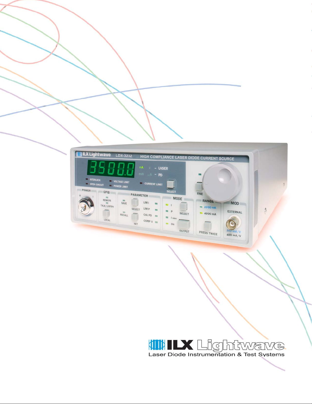
LDX-3232
High Compliance Current Source
ILX Lightwave Corporation · P. O. Box 6310 · Bozeman, MT, U.S.A. 59771 · U.S. & Canada: 1-800-459-9459 · International Inquiries: 406-556-2481 · Fax 406-586-9405
ilx.custhelp.com · www.ilxlightwave.com
70037800_R01_04_06


TABLE OF CONTENTS
TABLE OF CONTENTS
Safety Information and the Manual . . . . . . . . . . . . . . . . . . . . . . . . . . . . . . . . . ix
General Safety Considerations . . . . . . . . . . . . . . . . . . . . . . . . . . . . . . . . . . . . ix
Safety Marking Symbols . . . . . . . . . . . . . . . . . . . . . . . . . . . . . . . . . . . . . . . . . x
Comments, Suggestions, and Problems . . . . . . . . . . . . . . . . . . . . . . . . . . . xiii
Chapter 1 Introduction and Specifications
Product Overview . . . . . . . . . . . . . . . . . . . . . . . . . . . . . . . . . . . . . . . . . . . . . . . . 1
Initial Inspection . . . . . . . . . . . . . . . . . . . . . . . . . . . . . . . . . . . . . . . . . . . . . . . . . 2
Installing Your LDX-3232 High Compliance Current Source . . . . . . . . . . . . . . 2
Grounding Requirements . . . . . . . . . . . . . . . . . . . . . . . . . . . . . . . . . . . . . . . . 2
AC Line Power Requirements . . . . . . . . . . . . . . . . . . . . . . . . . . . . . . . . . . . . 2
GPIB Connector . . . . . . . . . . . . . . . . . . . . . . . . . . . . . . . . . . . . . . . . . . . . . . . 3
The GPIB Address . . . . . . . . . . . . . . . . . . . . . . . . . . . . . . . . . . . . . . . . . . . . . 3
Tilt-Foot Adjustment . . . . . . . . . . . . . . . . . . . . . . . . . . . . . . . . . . . . . . . . . . . . 3
Operating the LDX-3232 Precision Current Source . . . . . . . . . . . . . . . . . . . . 3
Maintenance . . . . . . . . . . . . . . . . . . . . . . . . . . . . . . . . . . . . . . . . . . . . . . . . . . . . . 5
Specifications . . . . . . . . . . . . . . . . . . . . . . . . . . . . . . . . . . . . . . . . . . . . . . . . . . . 6
Available Options and Accessories . . . . . . . . . . . . . . . . . . . . . . . . . . . . . . . . 8
Chapter 2 Operation
Applying Power to Your LDX-3232 . . . . . . . . . . . . . . . . . . . . . . . . . . . . . . . . . . . 9
The Power On Sequence . . . . . . . . . . . . . . . . . . . . . . . . . . . . . . . . . . . . . . . . 9
The Power On State . . . . . . . . . . . . . . . . . . . . . . . . . . . . . . . . . . . . . . . . . . . 10
04_06 LDX-3232 i

TABLE OF CONTENTS
Connecting to the Laser . . . . . . . . . . . . . . . . . . . . . . . . . . . . . . . . . . . . . . . . . . 10
Interlock Connections . . . . . . . . . . . . . . . . . . . . . . . . . . . . . . . . . . . . . . . . . . 12
Photodiode Connections . . . . . . . . . . . . . . . . . . . . . . . . . . . . . . . . . . . . . . . . 13
Setting the PD Bias . . . . . . . . . . . . . . . . . . . . . . . . . . . . . . . . . . . . . . . . . . . . 13
Grounding Considerations . . . . . . . . . . . . . . . . . . . . . . . . . . . . . . . . . . . . . . 13
Front Panel Operation . . . . . . . . . . . . . . . . . . . . . . . . . . . . . . . . . . . . . . . . . . . . 14
The Display . . . . . . . . . . . . . . . . . . . . . . . . . . . . . . . . . . . . . . . . . . . . . . . . . . 14
Operating a Laser in Constant Current (I) Mode . . . . . . . . . . . . . . . . . . . . . . 14
Setting Up the Precision Current Source . . . . . . . . . . . . . . . . . . . . . . . . . . . 15
Conditions That Will Automatically Shut Off the LASER OUTPUT . . . . . . . . 17
Operating a Laser in Constant Power (P) Mode . . . . . . . . . . . . . . . . . . . . . . . 17
Entering Photodiode Responsivity Values . . . . . . . . . . . . . . . . . . . . . . . . . . 17
Error Indicators . . . . . . . . . . . . . . . . . . . . . . . . . . . . . . . . . . . . . . . . . . . . . . . . . 19
Chapter 3 Remote Operation
Reading the GPIB Address . . . . . . . . . . . . . . . . . . . . . . . . . . . . . . . . . . . . . . 21
Changing the GPIB Address . . . . . . . . . . . . . . . . . . . . . . . . . . . . . . . . . . . . . 21
Changing Operation from Local to Remote . . . . . . . . . . . . . . . . . . . . . . . . . 22
LDX-3232 Current Source Command Set . . . . . . . . . . . . . . . . . . . . . . . . . . . . 22
Command Syntax . . . . . . . . . . . . . . . . . . . . . . . . . . . . . . . . . . . . . . . . . . . . . 22
Command Paths . . . . . . . . . . . . . . . . . . . . . . . . . . . . . . . . . . . . . . . . . . . . . . . . 25
IEEE488.2 Command Commands . . . . . . . . . . . . . . . . . . . . . . . . . . . . . . . . . . 26
LDX-3232 Frequently Used Commands . . . . . . . . . . . . . . . . . . . . . . . . . . . . . 27
Status Reporting . . . . . . . . . . . . . . . . . . . . . . . . . . . . . . . . . . . . . . . . . . . . . . . . 28
Event and Condition Registers . . . . . . . . . . . . . . . . . . . . . . . . . . . . . . . . . . . 28
Operation Complete Definition . . . . . . . . . . . . . . . . . . . . . . . . . . . . . . . . . . . 28
Output Off Register . . . . . . . . . . . . . . . . . . . . . . . . . . . . . . . . . . . . . . . . . . . . 30
Command Timing and Completion . . . . . . . . . . . . . . . . . . . . . . . . . . . . . . . . . 32
Error Messages . . . . . . . . . . . . . . . . . . . . . . . . . . . . . . . . . . . . . . . . . . . . . . . . . 32
ii LDX-3232

Chapter 4 Command Reference
LDX-3232 Device-Dependent Commands . . . . . . . . . . . . . . . . . . . . . . . . . . . . 39
LDX-3232 Device-Dependent Command Reference . . . . . . . . . . . . . . . . . . . . 40
Chapter 5 Functions and Features
Saving and Recalling from the Front Panel . . . . . . . . . . . . . . . . . . . . . . . . . . 83
TABLE OF CONTENTS
Saving and Recalling Under Remote Operation . . . . . . . . . . . . . . . . . . . . . . . 84
Using the Laser Compliance Voltage Adjustment . . . . . . . . . . . . . . . . . . . . . 84
Using the LDX-3232 Current Source’s Trigger Function . . . . . . . . . . . . . . . . 85
Using the LDX-3232 Current Sources’s BNC Interlock Connection . . . . . . . 86
BNC Interlock Usage Example . . . . . . . . . . . . . . . . . . . . . . . . . . . . . . . . . . . 86
Modulating the Laser Current Source . . . . . . . . . . . . . . . . . . . . . . . . . . . . . . . 86
Chapter 6 Calibration and Troubleshooting
Calibration Overview . . . . . . . . . . . . . . . . . . . . . . . . . . . . . . . . . . . . . . . . . . . . . 89
Recommended Equipment . . . . . . . . . . . . . . . . . . . . . . . . . . . . . . . . . . . . . . . . 90
Local Calibration of the LDX-3232 Current Source . . . . . . . . . . . . . . . . . . . . 91
Current Source Calibration . . . . . . . . . . . . . . . . . . . . . . . . . . . . . . . . . . . . . . 91
I
Current Calibration . . . . . . . . . . . . . . . . . . . . . . . . . . . . . . . . . . . . . . . . . 92
PD
Laser Forward Voltage Measurement Calibration . . . . . . . . . . . . . . . . . . . . 94
Remote Calibration of the LDX-3232 Current Source . . . . . . . . . . . . . . . . . . 95
Current Source Calibration . . . . . . . . . . . . . . . . . . . . . . . . . . . . . . . . . . . . . . 95
I
Current Calibration . . . . . . . . . . . . . . . . . . . . . . . . . . . . . . . . . . . . . . . . . 96
PD
Laser Forward Voltage Measurement Calibration . . . . . . . . . . . . . . . . . . . . 98
Troubleshooting Guide . . . . . . . . . . . . . . . . . . . . . . . . . . . . . . . . . . . . . . . . . . . 99
Error Messages . . . . . . . . . . . . . . . . . . . . . . . . . . . . . . . . . . . . . . . . . . . . . . . . 101
04_06 LDX-3232 iii

TABLE OF CONTENTS
iv LDX-3232

LIST OF FIGURES
LIST OF FIGURES
Figure 1.1 LDX-3232 Front View . . . . . . . . . . . . . . . . . . . . . . . . . . . .4
Figure 1.2 LDX-3232 Rear View . . . . . . . . . . . . . . . . . . . . . . . . . . . . .4
Figure 2.1 Common Laser Cathode - Photodiode Cathode . . . . . . .11
Figure 2.2 Common Laser Cathode - Photodiode Anode . . . . . . . .11
Figure 2.3 Common Laser Anode - Photodiode Cathode . . . . . . . .11
Figure 2.4 Common Laser Anode - Photodiode Anode . . . . . . . . . .12
Figure 2.5 Back Panel LD Connector . . . . . . . . . . . . . . . . . . . . . . . .12
Figure 3.1 LDX-3232 Command Path Structure . . . . . . . . . . . . . . . .25
Figure 3.2 LDX-3232 Status Reporting Schematic Diagram . . . . . .29
Figure 3.3 LDX-3232 Output Off Register . . . . . . . . . . . . . . . . . . . .31
Figure 4.1 Command Description Format . . . . . . . . . . . . . . . . . . . .39
Figure 5.1 LDX-3232 Rear Panel . . . . . . . . . . . . . . . . . . . . . . . . . . .85
Figure 6.1 I
Calibration Circuit . . . . . . . . . . . . . . . . . . . . . . . . . . .91
PD
04_06 LDX-3232 v

LIST OF FIGURES
vi LDX-3232

LIST OF TABLES
LIST OF TABLES
Table 2.1 LDX-3232 Default Settings. . . . . . . . . . . . . . . . . . . . . . . . .10
Table 2.2 LDX-3232 Error Indicators . . . . . . . . . . . . . . . . . . . . . . . . .19
Table 3.1 Substitute Parameter Names. . . . . . . . . . . . . . . . . . . . . . .23
Table 3.2 LDX-3232 Often Used Commands . . . . . . . . . . . . . . . . . .27
Table 3.3 LDX-3232 Default Settings for Output Off Registers . . . . .30
Table 3.4 Error Code Classifications . . . . . . . . . . . . . . . . . . . . . . . . .33
Table 3.5 LDX-3232 Error Codes. . . . . . . . . . . . . . . . . . . . . . . . . . . .33
Table 4.1 LDX-3232 Device-Dependent Commands. . . . . . . . . . . . .35
Table 6.1 Recommended Test Equipment. . . . . . . . . . . . . . . . . . . . .90
Table 6.2 Required Calibration Components. . . . . . . . . . . . . . . . . . .90
Table 6.3 Error Code Classifications . . . . . . . . . . . . . . . . . . . . . . . .101
Table 6.4 LDX-3232 Error Codes. . . . . . . . . . . . . . . . . . . . . . . . . . .101
04_06 LDX-3232 vii

LIST OF TABLES
viii LDX-3232
SAFETY AND WARRANTY INFORMATION
SAFETY AND WARRANTY INFORMATION
The Safety and Warranty Information section provides details about cautionary
symbols used in the manual, safety markings used on the instrument, and
information about the Warranty including Customer Service contact information.
Safety Information and the Manual
Throughout this manual, you will see the words Caution and Warning indicating
potentially dangerous or hazardous situations that, if not avoided, could result in
death, serious or minor injury, or damage to the product. Specifically:
Caution indicates a potentially hazardous situation that can result in minor or moderate
injury or damage to the product or equipment.
Warning indicates a potentially dangerous situation that can result in serious injury or
death.
WARNING
Visible and/or invisible laser radiation. Avoid direct exposure to the beam.
General Safety Considerations
If any of the following conditions exist, or are even suspected, do not use the
instrument until safe operation can be verified by trained service personnel:
• Visible damage
• Severe transport stress
• Prolonged storage under adverse conditions
• Failure to perform intended measurements or functions
If necessary, return the instrument to ILX Lightwave, or authorized local ILX
Lightwave distributor, for service or repair to ensure that safety features are
maintained (see the contact information on page xiii).
04_06 LDX-3232 ix
SAFETY SYMBOLS
All instruments returned to ILX Lightwave are required to have a Return
Authorization Number assigned by an official representative of ILX Lightwave
Corporation. See Returning an Instrument on page xi for more information.
SAFETY SYMBOLS
This section describes the safety symbols and classifications.
Technical specifications including electrical ratings and weight are included within
the manual. See the Table of Contents to locate the specifications and other
product information. The following classifications are standard across all ILX
Lightwave products:
• Indoor use only
• Ordinary Protection: This product is NOT protected against the harmful ingress of moisture.
• Class I Equipment (grounded type)
• Mains supply voltage fluctuations are not to exceed ±10% of the nominal supply voltage.
• Pollution Degree II
• Installation (overvoltage) Category II for transient overvoltages
• Maximum Relative Humidity: <80% RH, non-condensing
• Operating temperature range of 0°C to 40°C
• Storage and transportation temperature of -40°C to 70°C
• Maximum altitude: 3000 m (9843 ft.)
• This equipment is suitable for continuous operation.
x LDX-3232
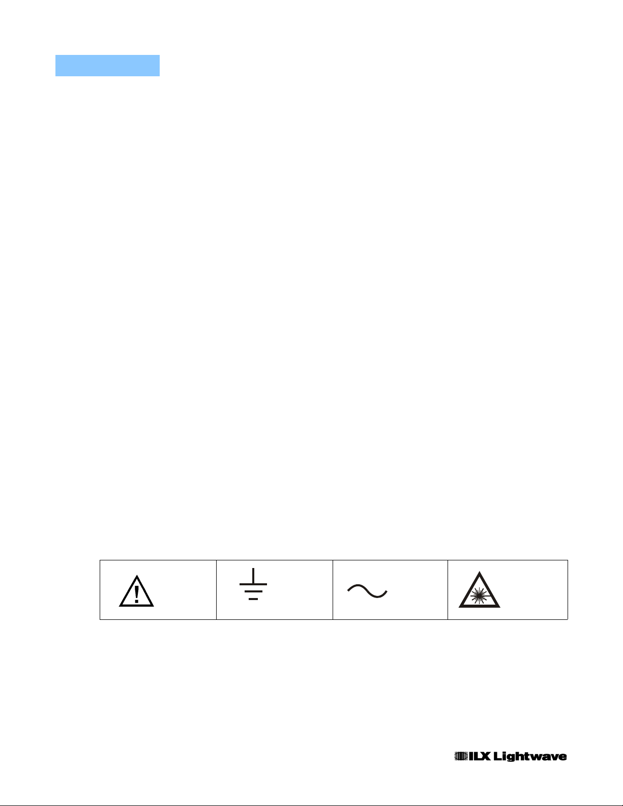
Safety Marking Symbols
This section provides a description of the safety marking symbols that appear on
the instrument. These symbols provide information about potentially dangerous
situations that can result in death, injury, or damage to the instrument and other
components.
Caution,
refer to
manual
Earth
ground
Te r mi n a l
Alternating
current
Visible and/or
invisible laser
radiation
WAR RA NT Y
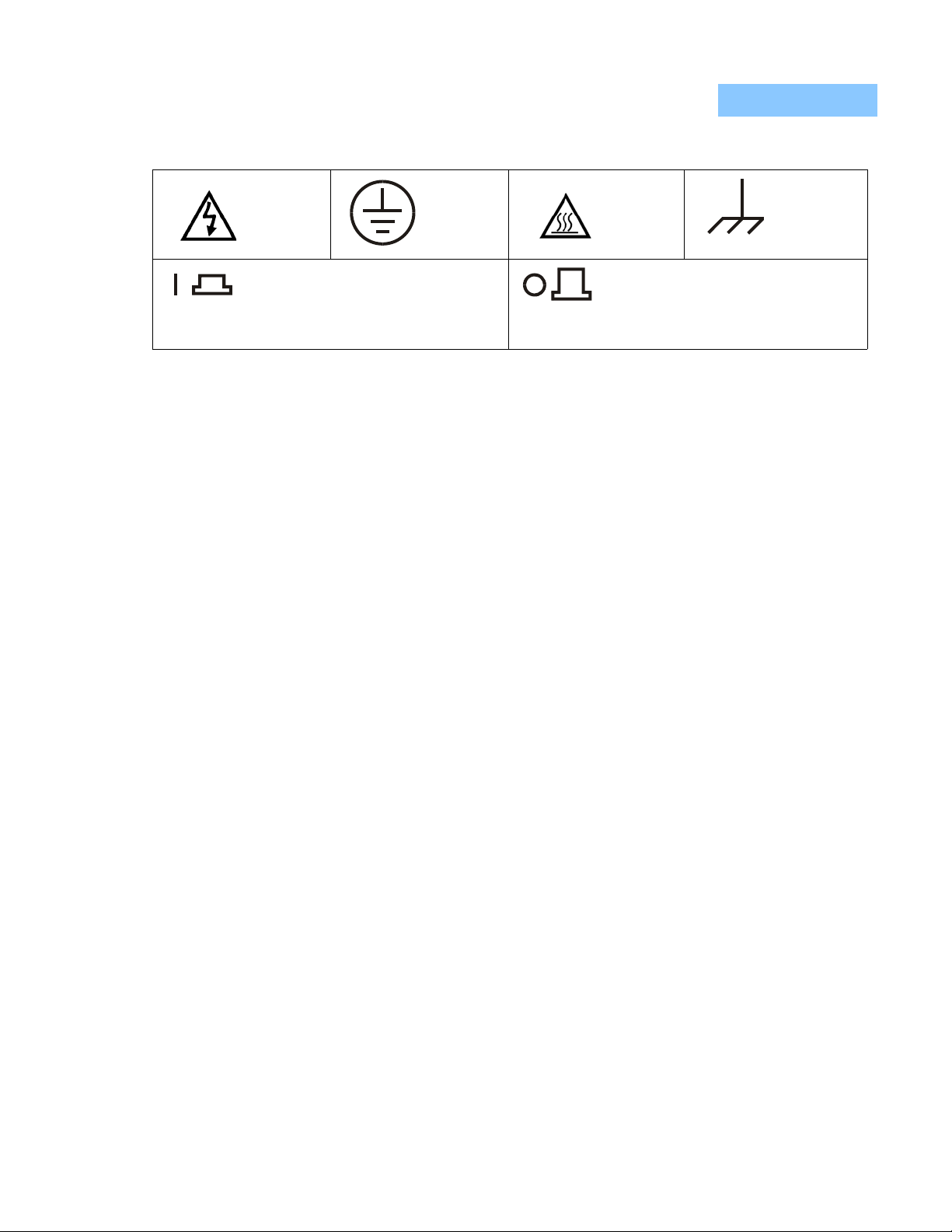
Caution, risk
of electric
shock
On: In position of a bistable push control.
The slash (I) only denotes that mains are on.
or
(I)
WARRANTY
ILX LIGHTWAVE CORPORATION warrants this instrument to be free from
defects in material and workmanship for a period of one year from date of
shipment. During the warranty period, ILX will repair or replace the unit, at our
option, without charge.
Limitations
This warranty does not apply to fuses, lamps, defects caused by abuse,
modifications, or to use of the product for that it was not intended.
Protective
Conductor
Te r mi n a l
or
(O)
Caution, hot
surface
Off: Out position of a bistable push control.
The circle (O) only denotes that mains are off.
Frame or
chassis
Te r mi n a l
This warranty is in lieu of all other warranties, expressed or implied, including any
implied warranty of merchantability or fitness for any particular purpose. ILX
Lightwave Corporation shall not be liable for any incidental, special, or
consequential damages.
If a problem occurs, please contact ILX Lightwave Corporation with the
instrument's serial number, and thoroughly describe the nature of the problem.
Returning an Instrument
If an instrument is to be shipped to ILX Lightwave for repair or service, be sure to:
1 Obtain a Return Authorization number (RA) from ILX Customer Service.
2 Attach a tag to the instrument identifying the owner and indicating the required service or
repair. Include the instrument serial number from the rear panel of the instrument.
3 Attach the anti-static protective caps that were shipped with the instrument and place the
instrument in a protective anti-static bag.
4 Place the instrument in the original packing container with at least 3 inches (7.5 cm) of
compressible packaging material. Shipping damage is not covered by this warranty.
5 Secure the packing box with fiber reinforced strapping tape or metal bands.
04_06 LDX-3232 xi

WAR RA NT Y
6 Send the instrument, transportation pre-paid, to ILX Lightwave. Clearly write the return
authorization number on the outside of the box and on the shipping paperwork. ILX
Lightwave recommends you insure the shipment.
If the original shipping container is not available, place your instrument in a
container with at least 3 inches (7.5 cm) of compressible packaging material on all
sides.
Repairs are made and the instrument returned transportation pre-paid. Repairs
are warranted for the remainder of the original warranty or for 90 days, thatever is
greater.
Claims for Shipping Damage
When you receive the instrument, inspect it immediately for any damage or
shortages on the packing list. If the instrument is damaged, file a claim with the
carrier. The factory will supply you with a quotation for estimated costs of repair.
You must negotiate and settle with the carrier for the amount of damage.
xii LDX-3232

WAR RA NT Y
Comments, Suggestions, and Problems
To ensure that you get the most out of your ILX Lightwave product, we ask that
you direct any product operation or service related questions or comments to ILX
Lightwave Customer Support. You may contact us in whatever way is most
convenient:
Phone . . . . . . . . . . . . . . . . . . . . . . . . . . . (800) 459-9459 or (406) 556-2481
Fax . . . . . . . . . . . . . . . . . . . . . . . . . . . . . . . . . . . . . . . . . . . . . (406) 586-9405
Online FAQ: . . . . . . . . . . . . . . . . . . . . . . . . . . . . . . . . . www.ilxlightwave.com
Or mail to:
ILX Lightwave Corporation
P. O. Box 6310
Bozeman, Montana, U.S.A 59771
www.ilxlightwave.com
When you contact us, please have the following information:
Model Number:
Serial Number:
End-User Name:
Company:
Phone:
Fax:
Description of what is
connected to the ILX
Lightwave instrument:
Description of the problem:
If ILX Lightwave determines that a return to the factory is necessary, you are
issued a Return Authorization (RA) number. Please mark this number on the
outside of the shipping box.
You or your shipping service are responsible for any shipping damage when
returning the instrument to ILX Lightwave; ILX recommends you insure the
shipment. If the original shipping container is not available, place your instrument
04_06 LDX-3232 xiii

WAR RA NT Y
in a container with at least 3 inches (7.5 cm) of compressible packaging material
on all sides.
We look forward to serving you even better in the future!
xiv LDX-3232

INTRODUCTION AND SPECIFICATIONS
Product Overview
CHAPTER 1
CHAPTER 1
INTRODUCTION AND SPECIFICATIONS
This chapter is an introduction to the LDX-3232 High Compliance Curren t Source.
This chapter contains first time setup information, important safet y considerations,
maintenance information, instrument specifications, and general LDX-3232
information.
If any of the following symptoms exist, or are even suspected, remove the LDX-3232
from service. Do not use the LDX-3232 until trained service personnel can verify safe
operation.
Visible damage
Severe transport stress
Prolonged storage under adverse conditions
Failure to perform intended measurements or functions
If necessary, return the LDX-3232 to ILX Lightwave for service and repair to ensure that
safety features are maintained.
Product Overview
The LDX-3232 instrument is a high compliance laser diode current source
intended for use with quantum cascade laser diodes and other devices requiring a
high compliance output. The LDX-3232 current source provides a high stability
output with multiple laser protection features and a fully redundant current limit.
The LDX-3232 offers the added benefits of dual laser interlocks and a GPIB
interface to allow full automation of testing.
04_06 LDX-3232 1

CHAPTER 1
INTRODUCTION AND SPECIFICATIONS
Initial Inspection
Initial Inspection
When you receive your LDX-3232 instrument, verify that the following items were
shipped with the instrument:
• LDX-3232 High Compliance Current Source
• LDX-3232 Series Instruction Manual
• Power Cord
• Shipping Kit
Installing Your LDX-3232 High Compliance Current Source
Grounding Requirements
The LDX-3232 High Compliance Current Source comes with a three conductor
AC power cable. The power cable must either be plugged into an approved threecontact electrical outlet or used with a three-contact or two-contact adapter with
the grounding wire connected to an electrical ground (safety ground). The
LDX-3232's power jack and supplied power cable meet IEC safety standards.
AC Line Power Requirements
You can operate the LDX-3232 instrument from a single phase power source
delivering nominal line voltages of 100, 120, 220-240 VAC (all values RMS), at
50/60 Hz. The line power voltage can vary ±10% but cannot exceed 250 VAC.
Maximum power consumption is 60 VA (Volt-Amps). The instrument's operational
voltage is factory configurable and need not be changed before operating the
instrument. However, check to be sure that the voltage printed on the back panel
of the instrument matches the power-line voltage in your area.
Before connecting the LDX-3232 High Compliance Current Source to a power source,
verify that the AC power source matches the setting of the LDX-3232's voltage printed on
the rear panel of the instrument.
T o avoid electrical shock hazard, connect the instrument to properly earth-grounded,
3-prong receptacles only. Failure to observe this precaution can result in severe injury or
death.
2 LDX-3232

INTRODUCTION AND SPECIFICATIONS
Installing Your LDX-3232 High Compliance Current Source
CHAPTER 1
GPIB Connector
The IEEE 488 GPIB interface connector is located on the rear panel, directly
above the power input module and fuse. See Figure 1.2, LDX-3232 Rear View.
Attach the GPIB cable to the 24-pin connector located on the rear panel. The
connector is tapered to ensure proper orientation. Using your fingers, tighten the
two screws on the cable connector.
A total of 15 devices can be connected together on the same GPIB interface bus.
The cables have single male/female connectors on each end so that several
cables can be stacked. This allows more than one cable to be attached to any
one device. However, the maximum length of the GPIB cables must not exceed
20 meters (65 feet) total or 2 meters (6.5 feet) per device.
The GPIB Address
The talk and listen addresses on the LDX-3232 High Compliance Current Source
are identical. This GPIB address is read locally by pressing the (GPIB) LOCAL
switch with the address displayed on the LED display . The instrument comes from
the factory configured with the GPIB address set to 1. You can change the
LDX-3232's GPIB address locally (via front panel). A procedure for changing the
address can be found in the section "Changing the GPIB Address" in Chapter 3.
Tilt-Foot Adjustment
The LDX-3232 High Compliance Current Source comes standard with folding
front legs and two rear feet for use as a bench top instrumen t. Extendin g the front
feet so that the instrument front panel sits up makes it easier to view the LED
displays. To use them, place the unit on a stable base and rotate the front legs
downward until they lock into position.
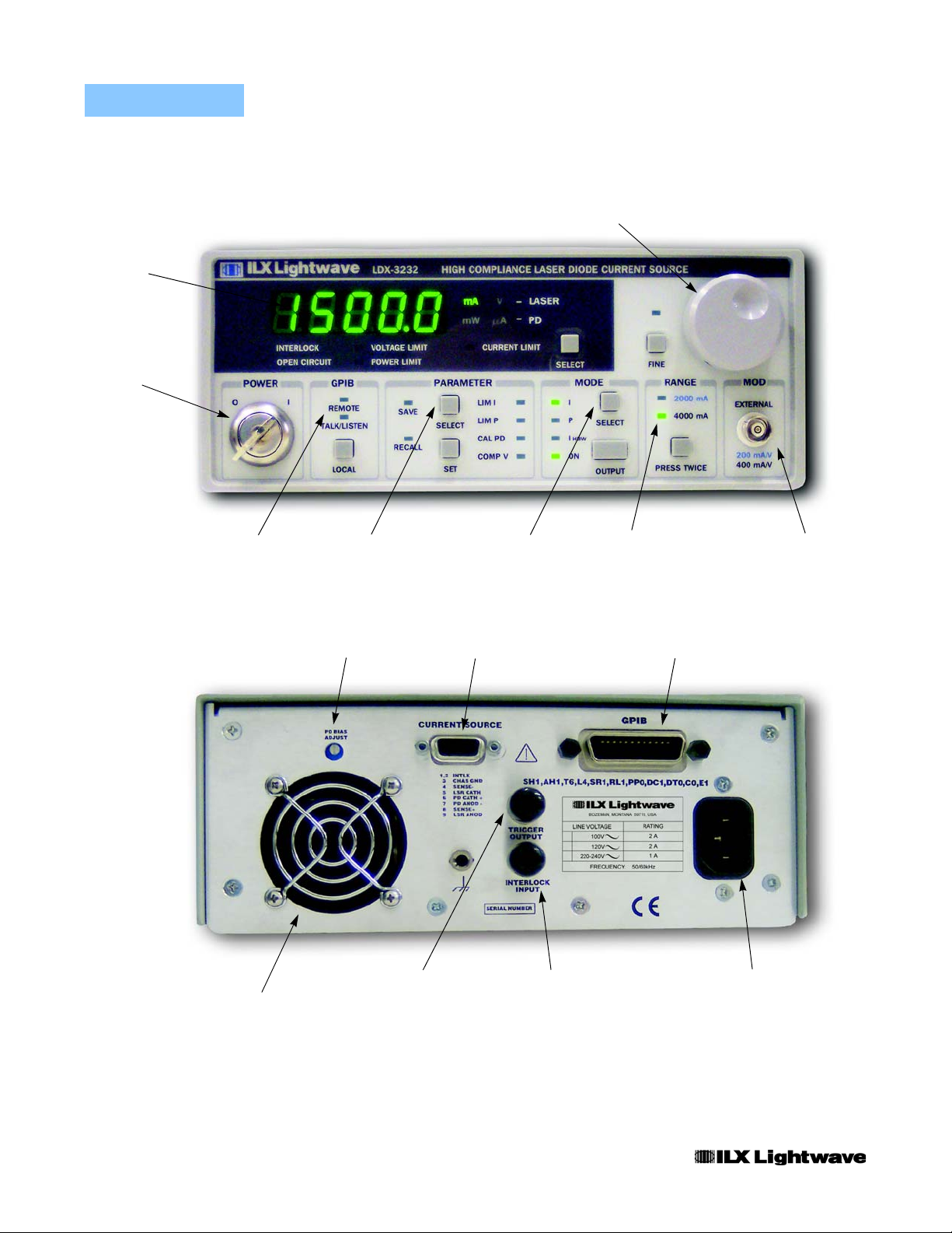
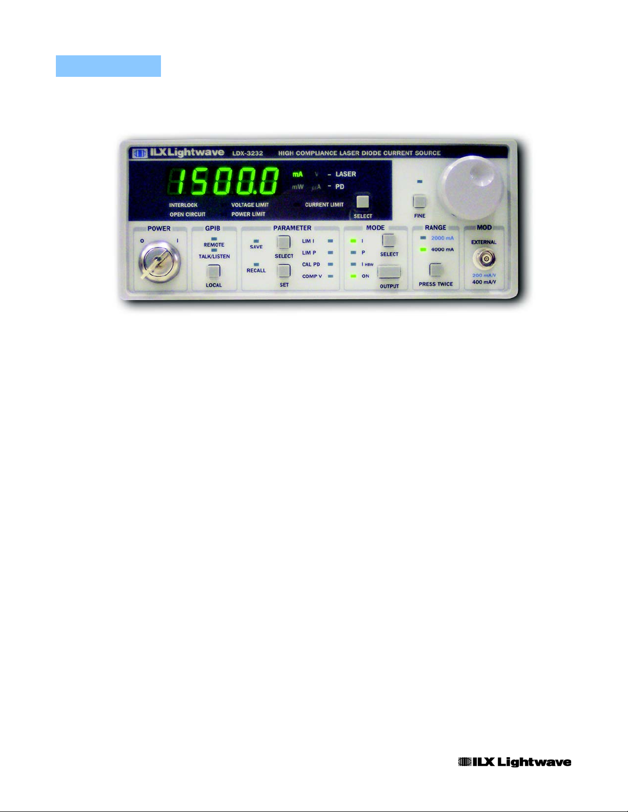
Operating the LDX-3232 Precision Current Source
Now that the LDX-3232 High Compliance Current Source is installed and ready
for use, you can begin to learn about its operation. The follo wing photos show the
functional keypad groupings, back panel connectors, and so on. Use these figures
to familiarize yourself with the LDX-3232. After that, use Chapter 2 for
fundamentals of operating your instrument.
04_06 LDX-3232 3
Display
Power
Switch
CHAPTER 1
INTRODUCTION AND SPECIFICATIONS
Installing Your LDX-3232 High Compliance Current Source
Adjust
Section
GPIB Section
Fan
Parameter
Selection
PD Bias Adjust
Laser Mode
Selection
Figure 1.1 LDX-3232 Front View
LD Connector
Trigger Output
Connector
Interlock Input
Connector
Current Range
Selection
GPIB Connector
Modulation Input
Connector
Power Cord
Connector
4 LDX-3232
Figure 1.2 LDX-3232 Rear View

INTRODUCTION AND SPECIFICATIONS
Maintenance
Maintenance
You may have to return your instrument to the ILX Lightwave facility at some time
for repair or service whether or not it is under warranty. There is a charge for
repairs after the warranty period has expired. Contact an ILX Lightwave service
representative for shipping instructions prior to returning the in strument. Have th e
model number, instrument serial number, and a description of the problem or
request at the time of the call. All ILX Lightwave instruments are identified by a
serial number located on the rear panel. The first four or five digits are the model
number; the last four digits are unique to the instrument and identify your
instrument specifically. A return authorization number will be given to you at the
time of your request for repair or service. Please use this number in all
communications concerning your instrument.
If you need to ship your LDX-3232 High Compliance Current Source back to the
factory for repair, be sure that the LDX-3232 is packaged in an enclosure with
cushioning material to prevent damage to the instrument during shipment (use the
original shipping containers and accessories if possible). Re-install the ESD
protective caps on the rear and front panels over the connectors (9 pin D, BNC,
and GPIB). Shipping damage is not covered under warranty.
CHAPTER 1
Attach a tag to the instrument identifying the owner and indicating the service or
repair needed. Include the model number and serial number. We suggest that you
insure the shipment.
In North America, contact ILX Lightwave for return authorization and shipping
instructions. Outside of North America, contact your ILX distributor for shipping
information.
For more information on how to obtain repair services, see the Safety and
Warranty section of this manual.
If cleaning is required, use a clean dry cloth. Do not use solvents.
Potentially lethal voltages exist within the LDX-3232 High Compliance Current Source. To
avoid electric shock, do not perform any of the maintenance on the instrument unless
you are qualified to do so. Qualified service personnel are required to wear protective
eyeglasses and anti-static wristbands while working on the LDX-3232 High Compliance
Current Source circuit boards. High voltages are present on and around the instrument’s
printed circuit boards.
04_06 LDX-3232 5
CHAPTER 1
INTRODUCTION AND SPECIFICATIONS
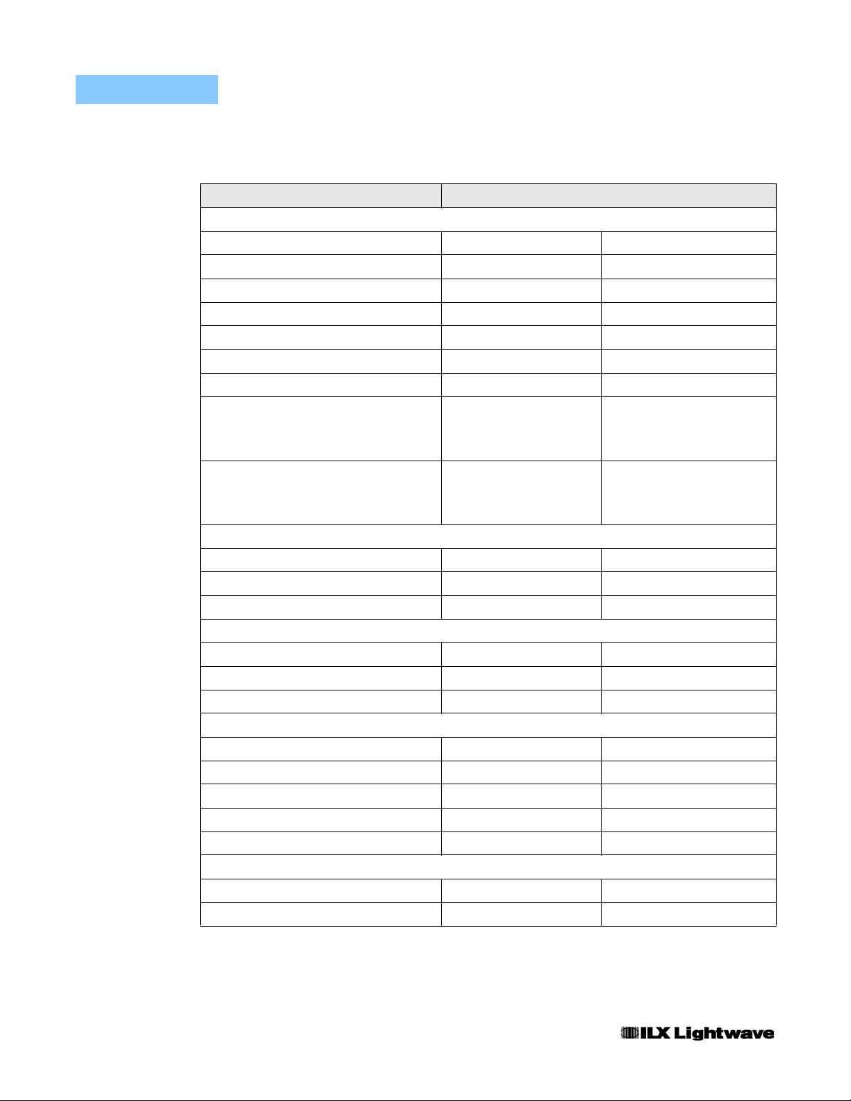
Specifications
Specifications
Drive Current Output
Output Current Range 0 to 2000 mA 0 to 4000 mA
Setpoint Resolution
Setpoint Accuracy (% of FS) ±0.05% ±0.05%
Compliance Voltage 0 - 15 V, adjustable 0 - 15 V, adjustable
Temperature Coefficient <100 ppm/°C <100 ppm/°C
Short Term Stability (1 hour)
Long Term Stability (24 hours)
Noise and Ripple (µA rms)
High Bandwidth Mode
Low Bandwidth Mode
Transients
Operational
1 kV EFT/Surge
LDX-3232
1
2
3
4
5
6
7
40 µA 80 µA
<20 ppm <20 ppm
<40 ppm <40 ppm
<20 µA
<20 µA
<4 mA
<8 mA
<40 µA
<20 µA
<4 mA
<8 mA
Compliance Voltage Adjust
Range 0 - 15 V 0 - 15 V
Resolution 10 mV 20 mV
Accuracy ±20% ±40%
Drive Current Limit Settings
Range 1 to 2020 mA 1 to 4040 mA
Resolution 10 mA 20 mA
Accuracy ±20 mA ±40 mA
Photodiode Feedback
Type Differential Differential
PD Reverse Bias 0 - 5V, adjustable 0 - 5V, adjustable
PD Current Range 5 to 10,000 µA 5 to 10,000 µA
Output Stability
Accuracy, setpoint (% of FS) ±0.05% ±0.05%
External Analog Modulation
Input 0 - 10 V, 1 kΩ 0 - 10 V, 1 kΩ
Transfer Function 200 mA / V 400 mA / V
8
±0.02% ±0.02%
6 LDX-3232
INTRODUCTION AND SPECIFICATIONS
Specifications
LDX-3232
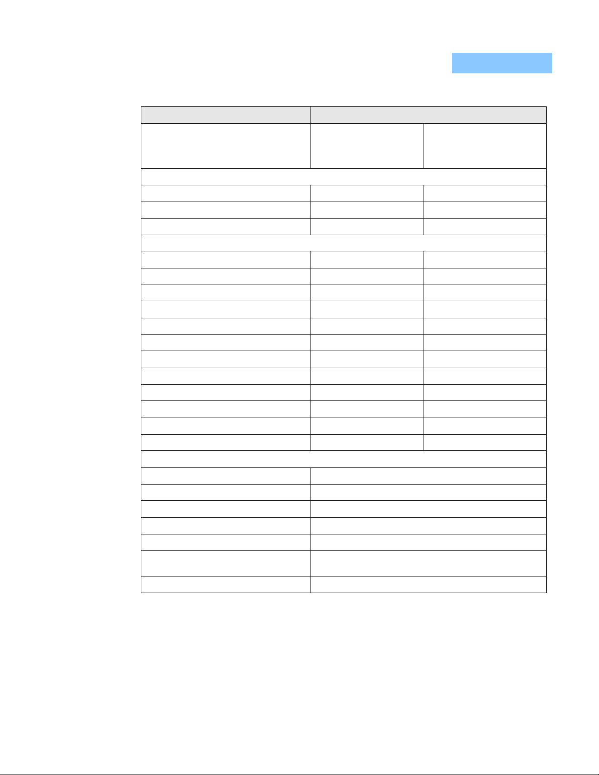
Bandwidth (3 dB)
High Bandwidth
Low Bandwidth
Trigge r Output
Type TTL TTL
Pulse Width 13 µs 13 µs
9
DC to 250 kHz
DC to 10 kHz
DC to 250 kHz
DC to 10 kHz
CHAPTER 1
Delay 12 ms 12 ms
Measurement (Display)
Output Current Range 0 to 2000.0 mA 0 to 4000.0 mA
Output Current Resolution
Photodiode Current Range 0 to 10,000 µA 0 to 10,000 µA
Photodiode Current Resolution 1 µA 1 µA
Photodiode Current Accuracy ±4 µA ±4 µA
PD Responsivity Range
PD Responsivity Resolution 0.01 µA/mW 0.01 µA/mW
Optical Power Range 0.00 to 5000.0 mW 0.00 to 5000.0 mW
Optical Power Resolution 0.1 mW 0.1 mW
Forward Voltage Range 0.000 to 10.000 V 0.000 to 10.000 V
Forward Voltage Resolution 1 mV 1 mV
Forward Voltage Accuracy
General
Size (H x W x D) 4” x 8.5” x 13.4”; 102 mm x 216 mm x 340 mm
Weight ~ 20 pounds (9 kg)
Power 100/120/230-240 V~; 2/2/1A 50/60 Hz
10
11
12
0.1 mA 0.1 mA
0.00 to 1000.00 µA/mW 0.00 to 1000.00 µA/mW
±2 mV ±2 mV
Temperature 0°C – 40°C operating; -40°C – 70°C storage
Humidity < 90% relative humidity, non-condensing
Laser Safety Features Key switch, interlock and output dela y (meets CDRH US
Display Type 5-digit, green LED
Notes
1. All values relate to a one-hour warm-up period at room temperature, 25°C.
2. Based on resolution of digital-to-analog converters used in the design.
3. Over any 1-hour period, half-scale output.
4. Over any 24-hour period, half-scale output.
5. Measured electrically with a 1 ohm load at half-scale output; evaluating spectral noise density over a 150kHz bandwidth from
125kHz to 275 kHz.
6. Maximum output current transient from normal operational situations (e.g., power on-off, current on-off), as well as accident al
situations (e.g., power line plug removal).
7. Maximum output current transient resulting from a 1000 V power-line transient spike. Tested to ILX Lightwave Technical Standard
#LDX-00196.
04_06 LDX-3232 7
21 CFR 1040.10)
CHAPTER 1
Available Options and Accessories
INTRODUCTION AND SPECIFICATIONS
Specifications
8. Maximum monitor photodiode current drift over any 30 minute period. Assumes zero drift in responsivity of photodiode.
9. 50% modulation at mid-scale output. Higher bandwidth is possible with smaller magnitude modulation signal.
10.Similar resolution available over GPIB.
11.Responsivity value is user-defined and is used to calculate the optical power.
12.Four wire voltage measured at the load. Voltage measurement accuracy while driving calibration load. Accuracy is dependent
upon load and cable used.
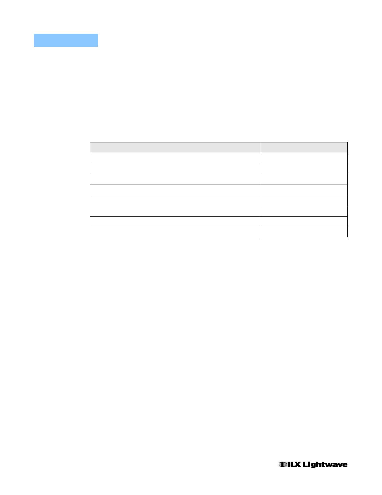
Options and accessories available for the LDX-3232 High Compliance Current
Sources include the following:
DESCRIPTION MODEL NUMBER
Noise Filter LNF-320
Current Source Interconnect Cable (terminated) CC-305S
Current Source Interconnect Cable (unterminated) CC-306S
DIL Laser Diode Mount LDM-4982
Butterfly Laser Diode Mount LDM-4894
High Power Laser Diode Mount LDM-4442
Single Rack Mount Kit RM-139
Dual Rack Mount Kit RM-140
Other laser diode mounts are available. Please contact ILX Lightwave for information on
additional options for your application.
Our goal is to make the best laser diode instrumentation available anywhere. To
achieve this, we need your ideas and comments on ways we can improve out
products. We invite you to contact us at any time with your suggestions.
8 LDX-3232
OPERATION
Applying Power to Your LDX-3232
CHAPTER 2
CHAPTER 2
OPERATION
This chapter introduces you to the operation of the LDX-3232 High Compliance
Current Source. It offers instructions for connecting your laser to the current
source and describes powering up the instrument. This chapter also cont ains step
by step procedures that teach you how to operate your current source in Const ant
Current Mode and Constant Power Mode. We recommend that you review the
contents of this chapter at a minimum before operating the LDX-3232 Current
Source.
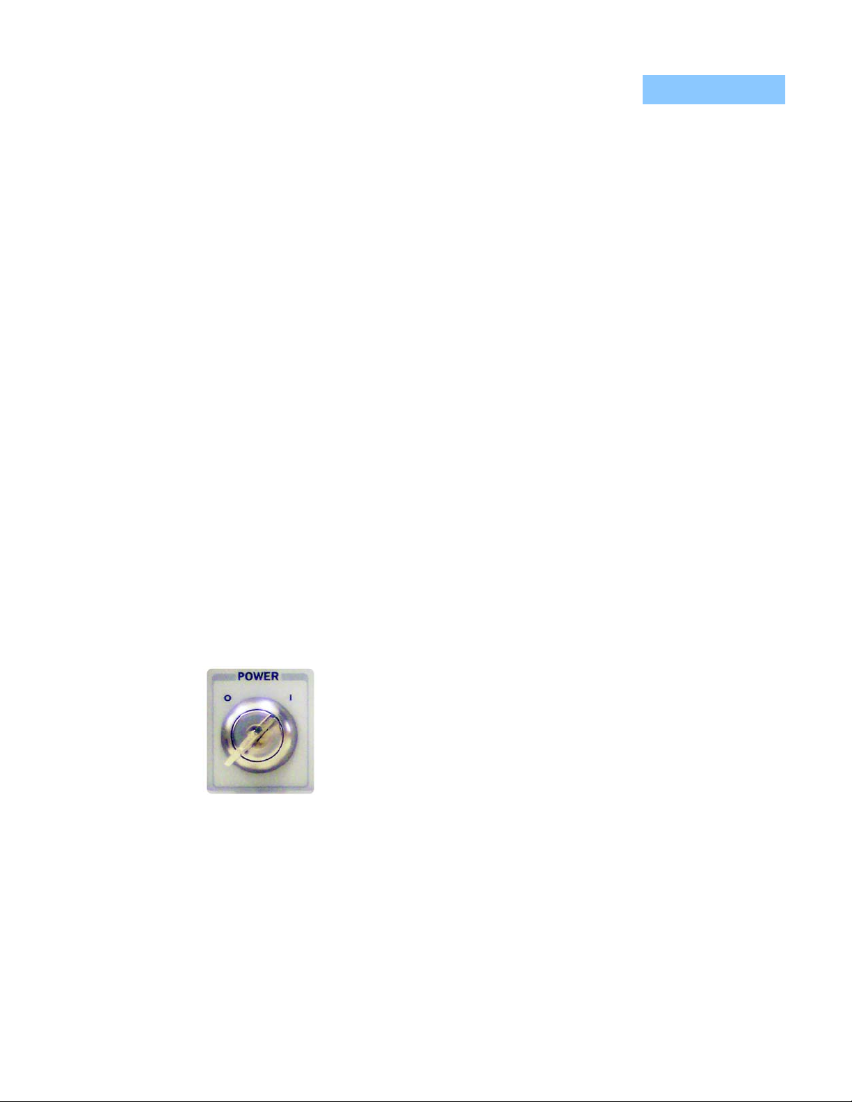
Applying Power to Your LDX-3232
To turn on the LDX-3232, rotate the key in the "POWER"
section of the front panel from "O" to "I". This action will initiate
the power on sequence. If the LDX-3232 does not appear to
turn on, verify that it is connected to line power. If line power is
not the problem, remove the power cord and check the voltage
selection block in addition to the line power fuse.
The Power On Sequence
During the power-up sequence, the following takes place. For about three
seconds all indicators light up, and all of the 7-segment displays indicate "8". Then
all lamps are turned off for three seconds. Next, the firmware version will be
displayed. Then, a self-test is performed to ensure that the instrument' s hardware
and processor are communicating. After this test, the instrument is ready to
operate and is configured to the state it was in when the power was last shut off.
04_06 LDX-3232 9
CHAPTER 2
The Power On State
OPERATION
Connecting to the Laser
You can choose to "clear" the last saved state by recalling the default values.
These values are stored in BINS to that you can save or recall instrument
configurations (described in more detail in Chapter 5). "BIN 0" contains all of the
default configurations listed in Table 2.1.
Note: If the instrument cannot successfully complete the power on test, an error message
of E-512 or E-513 will be displayed on the Display. See Chapter 3 for a list of error codes
and actions to take when your instrument indicates these errors.
Table 2.1 LDX-3232 Default Settings
GPIB mode in LOCAL via front panel, or in REMOTE via GPIB
PARAMETERS not selected
CAL PD = 0 µA / mW
LIM I (high range) = 1000 mA
LIM I (low range) = 500 mA
LIM V = 15 volts
LIM P = 5000 mW
Output off
DISPLAY enabled, in I mode
Constant I, low bandwidth mode selected
I setpoint = 0 mA
setpoint = 0 µA
I
PD
setpoint = 0 mW
P
PD
RECALL BIN number = 0
Connecting to the Laser
When connecting your laser to the LDX-3232, we recommend that the instrument
be powered up with the output off. In this condition, a low impedance shunt is
active across the output terminals. When disconnecting devices, it is only
necessary to turn the current source output off.
It is also recommended that the connections to the LDX-3232 output be made
using twisted wire pairs with an earth-grounded shield (see Figures 2.1 - 2.4). The
output terminals of the instrument are left floating relative to earth ground to
suppress AC power-on/power-off transients that may occur through an earthground path. If the output circuit is earth-grounded at some point (such as through
the laser package and mount), the user must be careful to avoid multiple earth
10 LDX-3232
OPERATION
Connecting to the Laser
CHAPTER 2
grounds in the circuit. Multiple earth grounds may provide circuit paths that induce
spurious currents in the photodiode feedback circuit and output leads.
Note: Cable connections to the laser must be secure! Loose connections can cause
momentary open circuits that can damage the laser.
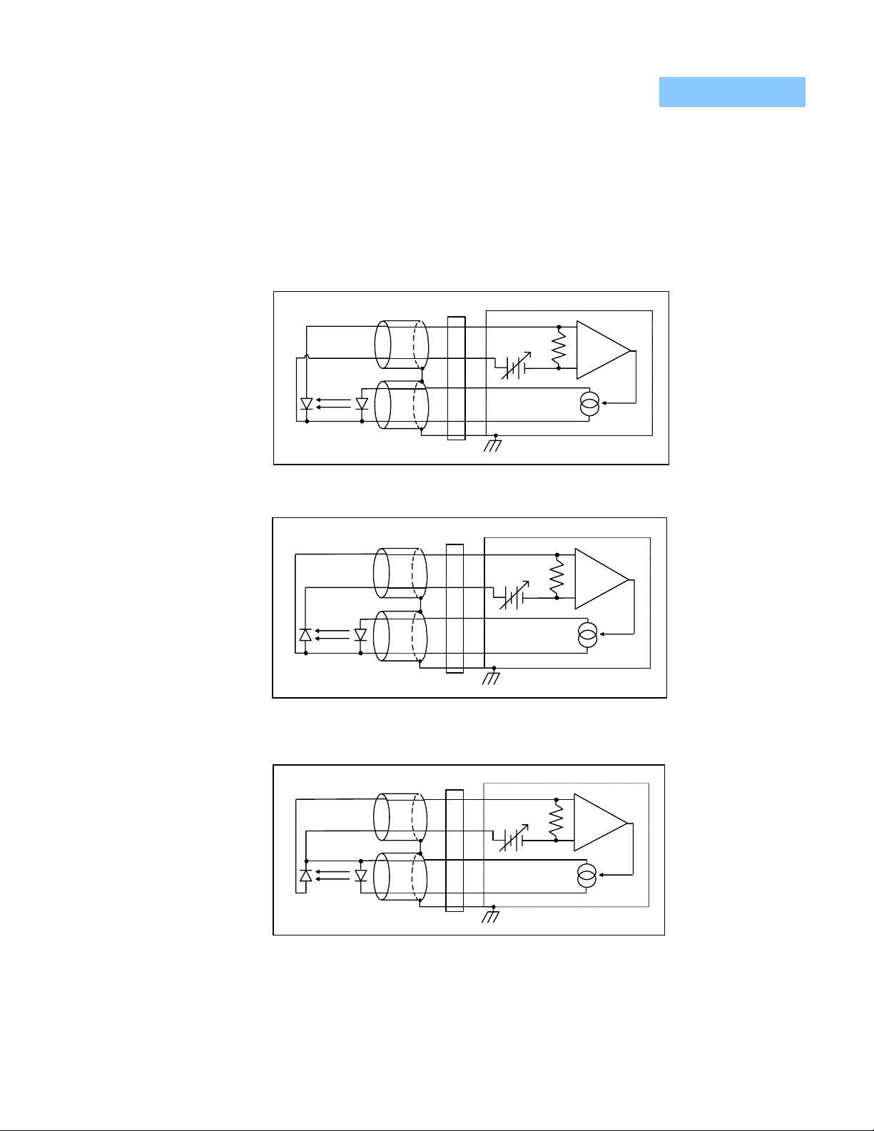
Figures 2.1 - 2.4 show the possible configurations of connecting laser diodes and
photodiodes with the LDX-3232 High Compliance Laser Current Source.
OUTPUT
LDX-3232 Current Source
7
Bias
+
6
+
-
9
5
P. D. L. D.
3
Earth Ground
Figure 2.1 Common Laser Cathode - Photodiode Cathode
P. D. L. D.
OUTPUT
LDX-3232 Current Source
7
Bias
+
6
9
5
3
+
-
Earth Ground
Figure 2.2 Common Laser Cathode - Photodiode Anode
P. D. L. D.
OUTPUT
LDX-3232 Current Source
7
Bias
+
6
9
5
3
+
-
Earth Ground
Figure 2.3 Common Laser Anode - Photodiode Cathode
04_06 LDX-3232 11
CHAPTER 2
OPERATION
Connecting to the Laser
P. D. L. D.
OUTPUT
LDX-3232 Current Source
7
Bias
+
6
9
5
3
+
-
Earth Ground
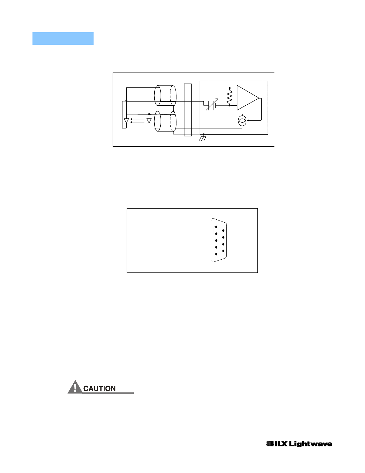
Figure 2.4 Common Laser Anode - Photodiode Anode
The 9-pin connector marked CURRENT SOURCE on the back panel is used to
connect your laser diode to the LDX-3232. There are connections provided for
laser cathode and anode, photodiode cathode and anode, chassis ground and
interlock. The pinout diagram for this connector is shown in Figure 2.5.
1, 2 Interlock
3 Chass is Groun d
4 Cathode Vo lta g e S ense
5 Laser Cathod e
6 PD Cathode ( + )
7 PD A n o d e ( -)
8 Anod e Voltage Sense
9 Laser Anode
1
6
2
7
3
8
4
9
5
12 LDX-3232
Figure 2.5 Back Panel LD Connector
Interlock Connections
In order for the laser output to be enabled a short circuit must exist between the
Interlock Pins (Pins 1 and 2) of the connector. The short can be a direct short
across the pins or a switch to prevent laser operation until the switch is closed. If a
short does not exist between these two pins, the INTERLOCK LED will illuminate
on the front panel and the laser output will be disabled.
Note: The BNC Interlock Connection from the BNC conne ctor on the rear panel will also
make the INTERLOCK LED illuminate. Please see the notes in chapter five on use of the
BNC interlock connection to learn more about its operation.
The interlock terminals on the LASER connector, pins 1 and 2, must be kept isolated
from all other connections including earth g round.

OPERATION
Connecting to the Laser
CHAPTER 2
Photodiode Connections
Many laser diode modules contain an internal photodiode that monitors the backfacet emission of the laser. Usually, this photodiode is internally connected to
either the laser anode or cathode.
The photodiode and laser connections to the LDX-3232 are electrically isolated
from ground and each other. So, if a 4 pin connection is made (no common
connections), no additional jumpers are required. Figures 2.1 - 2.4 show the
recommended connections and shielding for 3-pin lasers (where the common
connection is internal to the device). A 4-pin laser should be connected with the
same shielding as shown in Figure 2.1, but the common connection (between the
photodiode and the laser) is optional.
Setting the PD Bias
The LDX-3232 provides an adjustable reverse bias of 0-5 VDC for the photodiode.
To set the photodiode bias to 5 V reverse bias, turn the back panel PD BIAS
ADJUST fully clockwise. To set the photodiode bias to 0 V reverse bias, turn the
back panel PD BIAS ADJUST fully counter-clockwise.
Grounding Considerations
The LASER outputs of the LDX-3232 High Compliance Current Source are
isolated from chassis ground, allowing either output terminal to be grounded at the
user's option. Figures 2.1 - 2.4 show the proper earth-ground shielding for laser
diode/photodiode connections.
04_06 LDX-3232 13
CHAPTER 2
OPERATION
Front Pan el Operation
Front Panel Operation
This section describes fundamentals of operation for your LDX-3232 in two
operating modes: Constant Current (I) and Constant Power (P).
The Display
The digital display is used to show control parameters such as laser drive current
(mA), laser current limit (mA), laser forward voltage (V), voltage limit (V), monitor
photodiode current (µA), and laser optical power (mW) in both setpoint and
measurement modes. It will also display error codes that relate to LASER
operation. Error indicators underneath the display indicate control errors and are
explained in the section titled “ERROR INDICATORS”. All laser control
parameters are displayed on this digital display with the appropriate annunciator
illuminated.
Operating a Laser in Constant Current (I) Mode
Suppose you have an LDX-3232 and you want to run the instrument in Constant
Current, low bandwidth mode, with a setpoint of 1500 mA and a current limit of
1750 mA. This particular mode uses a low-pass filter on the laser drive current
output to significantly reduce noise. In this mode a modulation input of up to
10 kHz may be used via the front panel MOD EXTERNAL connector. Follow the
instructions below in the sequence presented.
14 LDX-3232
 Loading...