

Page 1
User’s Guide
Temperature Controller
LDT-5525
ILX Lightwave Corporation · P. O. Box 6310 · Bozeman, MT, U.S.A. 59771 · U.S. & Canada: 1-800-459-9459 · International Inquiries: 406-556-2481 · Fax 406-586-9405
ilx.custhelp.com · www.ilxlightwave.com
70019904_07_01
Page 2

Page 3

TABLE OF CONTENTS
TABLE OF CONTENTS
Safety Information and the Manual . . . . . . . . . . . . . . . . . . . . . . . . . . . . . . . . .vii
General Safety Considerations . . . . . . . . . . . . . . . . . . . . . . . . . . . . . . . . . . . .vii
Safety Marking Symbols . . . . . . . . . . . . . . . . . . . . . . . . . . . . . . . . . . . . . . . . viii
Comments, Suggestions, and Problems . . . . . . . . . . . . . . . . . . . . . . . . . . . . xi
Chapter 1 Introduction and Specifications
Product Overview . . . . . . . . . . . . . . . . . . . . . . . . . . . . . . . . . . . . . . . . . . . . . . . . 1
Available Options and Accessories . . . . . . . . . . . . . . . . . . . . . . . . . . . . . . . . 2
Specifications . . . . . . . . . . . . . . . . . . . . . . . . . . . . . . . . . . . . . . . . . . . . . . . . . . . 3
Chapter 2 Operation
AC Power Considerations . . . . . . . . . . . . . . . . . . . . . . . . . . . . . . . . . . . . . . . . . 7
Rack Mounting . . . . . . . . . . . . . . . . . . . . . . . . . . . . . . . . . . . . . . . . . . . . . . . . 7
Power-Up Sequence . . . . . . . . . . . . . . . . . . . . . . . . . . . . . . . . . . . . . . . . . . . . . . 8
Introduction to the LDT-5525 Front Panel . . . . . . . . . . . . . . . . . . . . . . . . . . . . . 8
Adjustments . . . . . . . . . . . . . . . . . . . . . . . . . . . . . . . . . . . . . . . . . . . . . . . . . 9
Display . . . . . . . . . . . . . . . . . . . . . . . . . . . . . . . . . . . . . . . . . . . . . . . . . . . . . 9
Parameters . . . . . . . . . . . . . . . . . . . . . . . . . . . . . . . . . . . . . . . . . . . . . . . . . 9
Parameter Setup . . . . . . . . . . . . . . . . . . . . . . . . . . . . . . . . . . . . . . . . . . . . 10
SENSOR CAL . . . . . . . . . . . . . . . . . . . . . . . . . . . . . . . . . . . . . . . . . . . . . . 10
Output . . . . . . . . . . . . . . . . . . . . . . . . . . . . . . . . . . . . . . . . . . . . . . . . . . . . 11
Control Mode . . . . . . . . . . . . . . . . . . . . . . . . . . . . . . . . . . . . . . . . . . . . . . . 11
Error Indicators . . . . . . . . . . . . . . . . . . . . . . . . . . . . . . . . . . . . . . . . . . . . . 11
Analog Output . . . . . . . . . . . . . . . . . . . . . . . . . . . . . . . . . . . . . . . . . . . . . . 12
Back Panel Controls and Connections . . . . . . . . . . . . . . . . . . . . . . . . . . . . . . 12
06_07 LDT-5525 i
Page 4

TABLE OF CONTENTS
SENSOR SELECT Switch . . . . . . . . . . . . . . . . . . . . . . . . . . . . . . . . . . . . . . 12
TEC Connector . . . . . . . . . . . . . . . . . . . . . . . . . . . . . . . . . . . . . . . . . . . . . . . 13
TEC Grounding Considerations . . . . . . . . . . . . . . . . . . . . . . . . . . . . . . . . . . 14
General Operating Procedures . . . . . . . . . . . . . . . . . . . . . . . . . . . . . . . . . . . . 15
Warm-Up and Environmental Considerations . . . . . . . . . . . . . . . . . . . . . . . 15
Temperature Mode Operation . . . . . . . . . . . . . . . . . . . . . . . . . . . . . . . . . . . 15
Resistance Mode Operation . . . . . . . . . . . . . . . . . . . . . . . . . . . . . . . . . . . . . 16
External Safety Switch Operation . . . . . . . . . . . . . . . . . . . . . . . . . . . . . . . . . 16
Booster Operation . . . . . . . . . . . . . . . . . . . . . . . . . . . . . . . . . . . . . . . . . . . . . 17
Chapter 3 Maintenance and Troubleshooting
Calibration Overview . . . . . . . . . . . . . . . . . . . . . . . . . . . . . . . . . . . . . . . . . . . . . 19
Recommended Equipment . . . . . . . . . . . . . . . . . . . . . . . . . . . . . . . . . . . . . . 20
Environmental Conditions . . . . . . . . . . . . . . . . . . . . . . . . . . . . . . . . . . . . . . . 20
Warm Up . . . . . . . . . . . . . . . . . . . . . . . . . . . . . . . . . . . . . . . . . . . . . . . . . . . . 20
Calibration Adjustments . . . . . . . . . . . . . . . . . . . . . . . . . . . . . . . . . . . . . . . . . . 21
Thermistor Calibration . . . . . . . . . . . . . . . . . . . . . . . . . . . . . . . . . . . . . . . . . 21
AD590 Sensor Calibration . . . . . . . . . . . . . . . . . . . . . . . . . . . . . . . . . . . . . . 22
LM335 Sensor Calibration . . . . . . . . . . . . . . . . . . . . . . . . . . . . . . . . . . . . . . 23
ITE Current Calibration . . . . . . . . . . . . . . . . . . . . . . . . . . . . . . . . . . . . . . . . . 24
Troubleshooting . . . . . . . . . . . . . . . . . . . . . . . . . . . . . . . . . . . . . . . . . . . . . . . . 25
Appendix A Steinhart-Hart Equation
Computer Program . . . . . . . . . . . . . . . . . . . . . . . . . . . . . . . . . . . . . . . . . . . . 29
Appendix B Sensing Current and Thermistor Selection
Thermistor Range . . . . . . . . . . . . . . . . . . . . . . . . . . . . . . . . . . . . . . . . . . . . . . . 33
Temperature Resolution . . . . . . . . . . . . . . . . . . . . . . . . . . . . . . . . . . . . . . . . 35
Selecting the Sensing Current . . . . . . . . . . . . . . . . . . . . . . . . . . . . . . . . . . . 35
ii LDT-5525
Selecting and Using Thermistors . . . . . . . . . . . . . . . . . . . . . . . . . . . . . . . . . 35
Page 5

TABLE OF CONTENTS
Appendix C AD590 and LM335 Sensor Calibration
AD590 Sensor . . . . . . . . . . . . . . . . . . . . . . . . . . . . . . . . . . . . . . . . . . . . . . . 37
LM335 Sensor . . . . . . . . . . . . . . . . . . . . . . . . . . . . . . . . . . . . . . . . . . . . . . . 38
One Point Calibration Method . . . . . . . . . . . . . . . . . . . . . . . . . . . . . . . . . . . . 40
Two Point Calibration Method . . . . . . . . . . . . . . . . . . . . . . . . . . . . . . . . . . . . 40
06_07 LDT-5525 iii
Page 6

TABLE OF CONTENTS
iv LDT-5525
Page 7

LIST OF FIGURES
LIST OF FIGURES
Figure 2.1 LDT-5525 Front Panel . . . . . . . . . . . . . . . . . . . . . . . . . . . .8
Figure 2.2 LDT-5525 Back Panel . . . . . . . . . . . . . . . . . . . . . . . . . . .12
Figure 2.3 Back Panel TEC Connector . . . . . . . . . . . . . . . . . . . . . .13
Figure A.1 Thermistor Resistance vs. Temperature . . . . . . . . . . . . .28
Figure B.1 Thermistor Temperature Range . . . . . . . . . . . . . . . . . . .34
Figure C.1 AD590 Nonlinearity . . . . . . . . . . . . . . . . . . . . . . . . . . . . .38
06_07 LDT-5525 v
Page 8

LIST OF FIGURES
vi LDT-5525
Page 9
SAFETY AND WARRANTY INFORMATION
The Safety and Warranty Information section provides details about cautionary
symbols used in the manual, safety markings used on the instrument, and
information about the Warranty including Customer Service contact information.
Safety Information and the Manual
Throughout this manual, you will see the words Caution and Warning indicating
potentially dangerous or hazardous situations which, if not avoided, could result in
death, serious or minor injury, or damage to the product. Specifically:
Caution indicates a potentially hazardous situation which can result in minor or
moderate injury or damage to the product or equipment.
Warning indicates a potentially dangerous situation which can result in serious injury or
death.
WARNING
Visible and/or invisible laser radiation. Avoid direct exposure to the beam.
General Safety Considerations
If any of the following conditions exist, or are even suspected, do not use the
instrument until safe operation can be verified by trained service personnel:
• Visible damage
• Severe transport stress
• Prolonged storage under adverse conditions
• Failure to perform intended measurements or functions
If necessary, return the instrument to ILX Lightwave, or authorized local ILX
Lightwave distributor, for service or repair to ensure that safety features are
maintained (see the contact information on
All instruments returned to ILX Lightwave are required to have a Return
Authorization Number assigned by an official representative of ILX Lightwave
Corporation.
See Returning an Instrument on page ix for more information.
page xi).
LDT-5525 vii
Page 10

SAFETY SYMBOLS
SAFETY SYMBOLS
This section describes the safety symbols and classifications.
Technical specifications including electrical ratings and weight are included within
the manual. See the Table of Contents to locate the specifications and other
product information. The following classifications are standard across all ILX
Lightwave products:
• Indoor use only
• Ordinary Protection: This product is NOT protected against the harmful ingress of moisture.
• Class I Equipment (grounded type)
• Mains supply voltage fluctuations are not to exceed ±10% of the nominal supply voltage.
• Pollution Degree II
• Installation (overvoltage) Category II for transient overvoltages
• Maximum Relative Humidity: <80% RH, non-condensing
• Operating temperature range of 0 °C to 40 °C
• Storage and transportation temperature of –40 °C to 70 °C
• Maximum altitude: 3000 m (9843 ft.)
• This equipment is suitable for continuous operation.
Safety Marking Symbols
This section provides a description of the safety marking symbols that appear on
the instrument. These symbols provide information about potentially dangerous
situations which can result in death, injury, or damage to the instrument and other
components.
Caution,
refer to
manual
Caution, risk
of electric
shock
On: In position of a bistable push control.
The slash (I) only denotes that mains are on.
or
(I)
Earth
ground
Te r mi n a l
Protective
Conductor
Te r mi n a l
Alternating
current
Caution, hot
surface
Off: Out position of a bistable push control.
The circle (O) only denotes that mains are off.
or
(O)
Visible and/or
invisible laser
radiation
Frame or
chassis
Te r mi n a l
viii LDT-5525
Page 11

WARRANTY
ILX LIGHTWAVE CORPORATION warrants this instrument to be free from
defects in material and workmanship for a period of one year from date of
shipment. During the warranty period, ILX will repair or replace the unit, at our
option, without charge.
Limitations
This warranty does not apply to fuses, lamps, defects caused by abuse,
modifications, or to use of the product for which it was not intended.
This warranty is in lieu of all other warranties, expressed or implied, including any
implied warranty of merchantability or fitness for any particular purpose. ILX
Lightwave Corporation shall not be liable for any incidental, special, or
consequential damages.
WAR RA NT Y
If a problem occurs, please contact ILX Lightwave Corporation with the
instrument's serial number, and thoroughly describe the nature of the problem.
Returning an Instrument
If an instrument is to be shipped to ILX Lightwave for repair or service, be sure to:
1 Obtain a Return Authorization number (RA) from ILX Customer Service.
2 Attach a tag to the instrument identifying the owner and indicating the required service or
repair. Include the instrument serial number from the rear panel of the instrument.
3 Attach the anti-static protective caps that were shipped with the instrument and place the
instrument in a protective anti-static bag.
4 Place the instrument in the original packing container with at least 3 inches (7.5 cm) of
compressible packaging material. Shipping damage is not covered by this warranty.
5 Secure the packing box with fiber reinforced strapping tape or metal bands.
6 Send the instrument, transportation pre-paid, to ILX Lightwave. Clearly write the return
authorization number on the outside of the box and on the shipping paperwork. ILX
Lightwave recommends you insure the shipment.
If the original shipping container is not available, place your instrument in a
container with at least 3 inches (7.5 cm) of compressible packaging material on all
sides.
Repairs are made and the instrument returned transportation pre-paid. Repairs
are warranted for the remainder of the original warranty or for 90 days, whichever
is greater.
06_07 LDT-5525 ix
Page 12

WAR RA NT Y
Claims for Shipping Damage
When you receive the instrument, inspect it immediately for any damage or
shortages on the packing list. If the instrument is damaged, file a claim with the
carrier. The factory will supply you with a quotation for estimated costs of repair.
You must negotiate and settle with the carrier for the amount of damage.
x LDT-5525
Page 13

WAR RA NT Y
Comments, Suggestions, and Problems
To ensure that you get the most out of your ILX Lightwave product, we ask that
you direct any product operation or service related questions or comments to ILX
Lightwave Customer Support. You may contact us in whatever way is most
convenient:
Phone . . . . . . . . . . . . . . . . . . . . . . . . . . . (800) 459-9459 or (406) 586-1244
Fax . . . . . . . . . . . . . . . . . . . . . . . . . . . . . . . . . . . . . . . . . . . . . (406) 586-9405
On the web at: . . . . . . . . . . . . . . . . . . . . . . . . . . . . . . . . . . . .ilx.custhelp.com
Or mail to:
ILX Lightwave Corporation
P. O. Box 6310
Bozeman, Montana, U.S.A 59771
www.ilxlightwave.com
When you contact us, please have the following information:
Model Number:
Serial Number:
End-user Name:
Company:
Phone:
Fax:
Description of what is
connected to the ILX
Lightwave instrument:
Description of the problem:
If ILX Lightwave determines that a return to the factory is necessary, you are
issued a Return Authorization (RA) number. Please mark this number on the
outside of the shipping box.
You or your shipping service are responsible for any shipping damage when
returning the instrument to ILX Lightwave; ILX recommends you insure the
shipment. If the original shipping container is not available, place your instrument
06_07 LDT-5525 xi
Page 14

WAR RA NT Y
in a container with at least 3 inches (7.5 cm) of compressible packaging material
on all sides.
We look forward to serving you even better in the future!
xii LDT-5525
Page 15

CHAPTER 1
INTRODUCTION AND SPECIFICATIONS
This manual contains operation and maintenance information for the LDT 5525
Temperature Controller. If you want to get started right away, read Chapter 2,
which covers Operation, first.
Product Overview
The LDT-5525 Temperature Controller is a microprocessor-based, precision
thermoelectric temperature controller designed for temperature control of laser
diodes, detectors and other temperature sensitive devices. The LDT 5525 ca n be
used for laser diode testing, laser diode frequency stabilization, IR detector
cooling, and to determine the characteristics of electronic devices. The LDT-5525
combines high analog stability with the versatility of a microprocessor-based
instrument. The internal microprocessor controls the operation of the LDT-5525
and performs the non-linear conversion of thermistor resistance to temperature
based on two user-defined constants.
You can configure the LDT-5525 to operate with a wide variety of thermistor
temperature sensors and TE modules, as well as AD590 series and LM335 series
temperature sensors.
Features of the LDT-5525 include:
• Intuitive front panel layout
• Large and easy-to-read green LED display
• Display resolution of 0.1 degree Centigrade
• Output current limit control to safely operate al l TE coolers
• Configurable for a variety of thermal sensors
• Output will supply 4 amps, 24 Watts
• Closed-case calibration
LDT-5525 1
Page 16
CHAPTER 1
Available Options and Accessories
INTRODUCTION AND SPECIFICATIONS
Product Overview
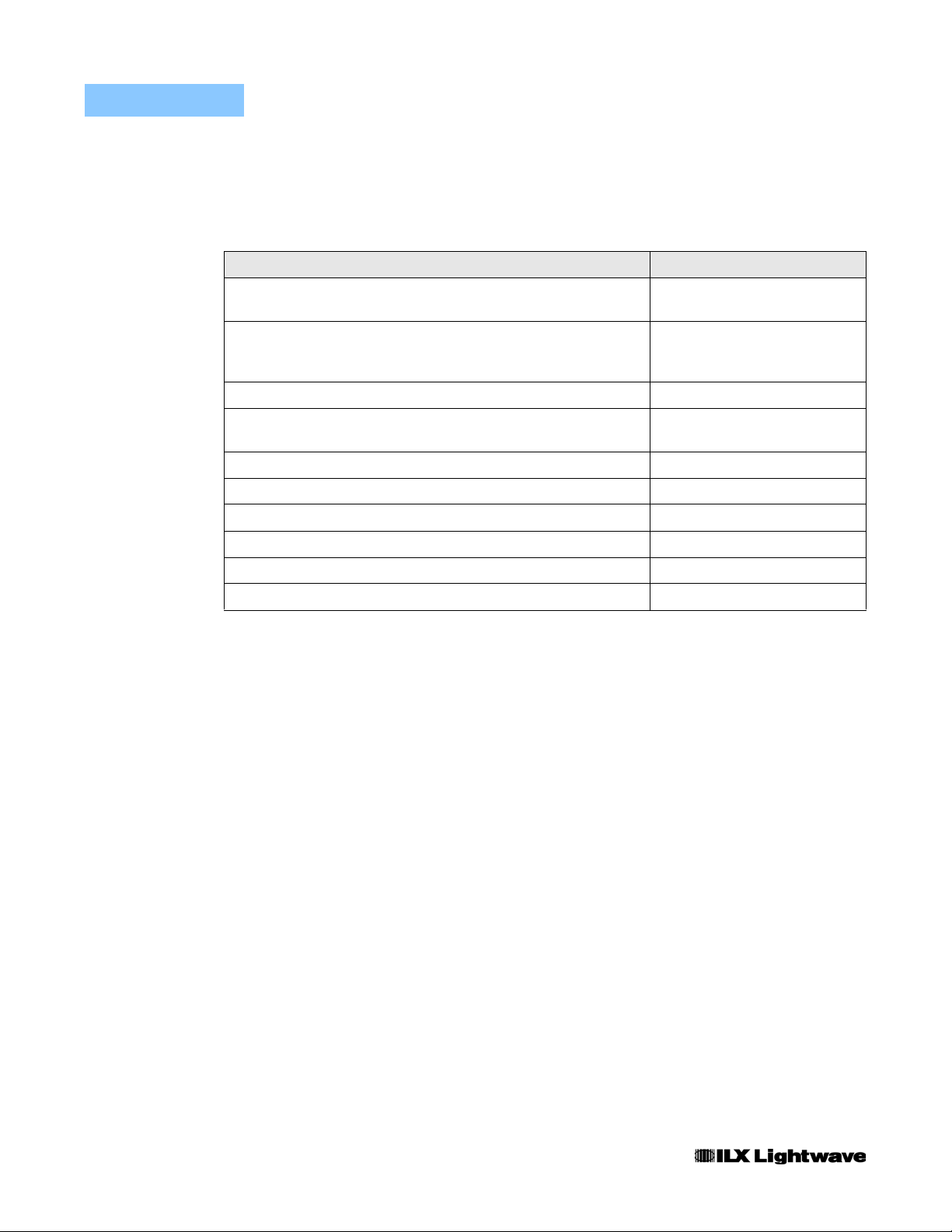
Options and accessories available for the LDT-5525 Temperature Controller
include the following:
DESCRIPTION MODEL NUMBER
Single Rack mount kit
(enables installation into a standard 19” rack)
134
Dual Rack mount kit
(enables installation of two LDT-5525 instruments into a standard
19” rack)
Temperature Controlled Laser Diode Mount 4407
Temperature Controlled Laser Diode Mount
(available with collimating assembly)
High Power Laser Diode Mount 4442
Temperature Controller Interconnect Cable (unterminated) 501
Calibrated 10 Kohm Thermistor 510
Uncalibrated 10 Kohm Thermistor 520
Uncalibrated AD590LH IC Temperature Sensor 530
Uncalibrated LM335 IC Temperature Sensor 540
135
4412
Other Laser Diode Mounts are available. Please contact ILX Lightwave for
information on additional options for your applications.
2 LDT-5525
Page 17

Specifications
1
Output
Output Type Bipolar constant current source
Control Algorithm Smart Integrator, Hybrid PI
Compliance Voltage 6 Volts at 4 Amps
Maximum Current Output 4 Amps
Maximum Output Power
Current Limit Control Range
Current Limit Accuracy
Ripple / Noise
Temperature Control
Temperature Range
Sensor Type 2-wire thermistor, LM335 voltage type or AD590
3
INTRODUCTION AND SPECIFICATIONS
Specifications
2
24 Watts, typical
CHAPTER 1
0 to 4.4 Amps
+50 mA
<1 mA
4
-99 to 199.9oC
-20 to +70oC with typical (NTC) 10K thermistor
currenty type
Thermistor Sensing Current 10 µA or 100 µA
Temperature Set Point Resolution 0.1oC
Short Therm Stability
Long Term Stability +0.01oC
1 Output current and power are rated into a 1 ohm load
2 Higher output powers can be accommodated by using an external booster. Contact ILX Lightwave for further
information
3 Broadband noise (10 Hz to 10 MHz) is measured at 1 Amp output current
4 Temperature control range depends primarily on the type of thermistor and TE module used. The range can be
extended higher or lower by selecting appropriate components; see Appendix B for more details
5 Short term temperature stability is a strong function of the thermal environment of the thermistor and TE module;
room air currents in particular can easily cause fluctuations of 0.1
5
+0.005oC
o
C in an exposed mounting configuration
06_07 LDT-5525 3
Page 18

CHAPTER 1
INTRODUCTION AND SPECIFICATIONS
Specifications
Thermistor Range (10 µA) 0.0 to 450.0 KΩ
Thermistor Range (100 µA) 0.0 to 45.0 KΩ
Usable Thermistor Range 25 to 450,000 Ω, typical
Thermistor Resistance Resolution
(10 µA)
Thermistor Resistance Resolution
(100 µA)
Thermistor Resistance Accuracy +0.05% of FS
AD590 Reverse Bias 8 Volts
LM335 Bias 0.6 mA
User Calibration
Thermistor Steinhart-Hart equation (2 constants)
IC Sensor 2-point
Measurement (Display
Display Type 4-digit LED
TE Current Range -4.00 to 4.00 Amps
TE Current Resolution 0.01 Amps
TE Current Accuracy +0.03 Amps
Temperature Range -99.9 to 999.9oC
Temperature Resolution 0.1oC
Temperature Accuracy
6 Accuracy figures quoted are typical for a calibrated 10K thermistor; accuracy figures are relative to calibration
standard and are dependent on the user-defined configuration of the instrument; variation from typical value is
largely due to uncertainty in thermistor calibration
6
0.1 kΩ
0.01 kΩ
0oC: 0+0.6oC, typical
20oC: +0.3oC, typical
30oC: +0.4oC, typical
50oC: +0.6oC, typical
4 LDT-5525
Page 19

INTRODUCTION AND SPECIFICATIONS
Specifications
General
Output Connectors TEC I/O: 15-pin, D-sub
Analog Output: BNC
Size 3.5” x 7.3” x 12”
Weight 8.0 pounds
Power Requirements 90 - 125 VAC, 105 - 250 VAC (jumper selectable)
at 50-60 Hz
Ambient Temperature Range 0 to +40 oC operating
-40 to +70 oC storage
Humidity < 85% relative humidity, non-condensing
Warm-Up 1 hour to rated accuracy
CHAPTER 1
Our goal is to make the best laser diode instrumentation available anywhere. To
achieve this, we need your ideas and comments on ways we can improve out
products. We invite you to contact us at any time with your suggestions.
06_07 LDT-5525 5
Page 20

CHAPTER 1
INTRODUCTION AND SPECIFICATIONS
Specifications
6 LDT-5525
Page 21

CHAPTER 2
OPERATION
This chapter describes how to install, adjust, and operate the LDT-5525
Temperature Controller. It is divided into sections covering installation,
familiarization and adjustment, and normal operating procedures.
This chapter also gives an overview of the LDT-5525's front panel fe atures, an d it
presents a guide to quickly familiarize the user with the front panel operations.
Installation procedures and considerations are also covered in this chapter.
AC Power Considerations
The LDT-5525 Series Controllers can be configured to operate at nominal line
voltages of 100, 120 220, 230-240 VAC (all ±10%). This is done at the factory and
need not be changed before operating the instrument. However, check to be sure
that the voltage printed on the back panel of the instrument matches the powerline voltage in your area.
T o avoid electrical shock hazard, connect the instrument to properly earth-grounded, 3prong receptacles only. Failure to observe this precaution can result in severe injury or
death.
Rack Mounting
The LDT 5525 Series Precision Temperature Controller may be rack mounted by
installing a rack mount flange on either side of the enclosure. All rack mount
accessory kits contain detailed mounting instructions. Refer to Chapter 1 for
applicable rack mount accessory part numbers.
LDT-5525 7
Page 22

CHAPTER 2
L
R
T
Ω
A
R
T
I
E
T
T
Y
R
I
OPERATION
Power-Up Sequence
Power-Up Sequence
With the LDT-5525 Series Precision Temperature Controller connected to an AC
power source, pressing the POWER switch will supply power to the instrument
and start the power up sequence.
During the power-up sequence, the following takes place. For about two seconds
all indicators light up, and all of the 7-segment displays indicate "8". Then all
lamps are turned off for two seconds. Then, the sensor switch position is
displayed for two seconds. After this, the unit is configured to the state it was in
when the power was last shut off (except for the display mode which defaults to I
TE measurement). The adjust knob is always disabled at power up.
Introduction to the LDT-5525 Front Panel
The LDT-5525 Temperature Controller's front panel contains displays and controls
for the Temperature Controller hardware. Each of the labeled areas on the front
panel (i.e. DISPLAY or MODE) is described in this chapter.
Refer to Figure 2.1 for the following discussions of the LDT-5525 Temperature
Controller front panel sections. The key words are in capital letters for quick
identification.
Error Parameter Display Adjust Adjust
Indicators Switch Switch Enable Knob
Switch
LDT -5525
TE O PENSENS OR OPEN
POWE
ANALO G O U
100 C/V
10 k
100 k
/V
Ω
/V
Ω
AC POWER Analog CAL Mode Output
ON/Off Output Select Select On/Off
Switch Connector Switch Switch Switch
T EMPERA TURE CONT ROLL ER
k
C
SENS OR CA
C1
C2
TE
SENS OR
VI EW SET
PARA MET E
I LI MIT
T LI MIT
GAIN
DISPL A
ADJUS
ENBL
MOD
TE
OUT PU
ON
Figure 2.1 LDT-5525 Front Panel
8 LDT-5525
Page 23

OPERATION
Introduction to the LDT-5525 Front Panel
CHAPTER 2
Adjustments
The ADJUST section contains the Adjust knob for entering values, and it co nta ins
the ENBL (adjust enable) switch and indicator. In order to make any adjustment,
the ENBL indicator must be lit. Pressing the ENBL switch toggles the ENBL
indicator on or off.
Display
The display is used to show measurements, output set point, and parameter set
points. Whenever a set point is being displayed, the VIEW SET indicator will be lit.
The DISPLAY switch is used to select the measured current (I TE), temperature,
resistance, or the set point value. The set point type is determined by the MODE
selection. Repeatedly pressing the DISPLA Y switch will cycle the display from ITE
to temperature to resistance (with thermistor sensors only) to set point and back to
ITE, and so on.
When in I TE mode, the set point will be TE current.
When in R mode, the set point will be thermistor resistance in KΩ. R mode is not
available if the back panel SENSOR SELECT switch is set to LM335 or AD590.
R mode operation may offer improved set point resolution (over T mode),
depending on the desired temperature set point.
Note: The resistance set point is NOT maintained if the control mode is changed
(e. g. from R mode to T mode). Also, if the SENSOR SELECT switch is moved from 10 µA
to 100 µA while in R mode, the resistance set point will be rounded to match the display
resolution.
When in T mode the set point will be temperature in oC.
When the output is off and a measurement is displayed, if the adjust knob is
turned the control mode set point will be displayed for three seconds. If the set
point is adjusted (by turning the adjust knob) the set point timer will be restarted.
Therefore, three seconds after the set point is adjusted the display will return to
the last measurement.
Parameters
The LDT-5525 Temperature Controller allows adjustment of the following
parameters, I LIMIT (TE current limit), T LIMIT (temperature limit) and GAIN
(sensor feedback amplifier gain). In addition, the sensor calibration values may be
entered.
The LDT-5525 will limit the I TE output to the I LIMIT value, regardless of the set
point or control mode.
06_07 LDT-5525 9
Page 24

CHAPTER 2
OPERATION
Introduction to the LDT-5525 Front Panel
The temperature is limited (via the sensor feedback) to the T LIMIT value. If the
sensor reads a temperature which is greater than T LIMIT, the I TE output will be
shut off.
The GAIN value is used to control the sensor feedback gain, and thus the
temperature settling time and overshoot. If the GAIN is set too low (1 is the lowest
setting) the TE cooler will take longer to reach the temperature set point. If the
GAIN is set too high (300 is the highest setting) the actual temperature may
oscillate around the set temperature.
The optimum GAIN setting depends on the type of TE cooler and temperature that
you are setting . Set the GAIN to its lowest value and th en try increasing it until the
temperature oscillates around the set temperature. Then, reduce the GAIN one
step.
Parameter Setup
The PARAMETER switch is used to view and edit the parameters. Repeatedly
pressing the PARAMETER switch will cycle through the parameters.
When a parameter is selected for viewing, its value will remain on the display for
three seconds. If an adjustment is made to the parameter (by turning the adjust
knob) the three second timer will be restarted. Three seconds af te r the p ar ameter
adjustment is done, the display will revert to the last measurement mode.
SENSOR CAL
These are the constants of the Steinhart-Hart equation that the user enters to
calibrate the TEC for different thermistors' temperature conversions. The
Steinhart-Hart equation is used to derive temperature from the non-linear
resistance of an NTC (Negative Temperature Coefficient) thermistor. For
information on setting C1 and C2 for thermistors, see Appendix A. For information
on thermistor selection and sensor current selection, see Appendix B.
When a linear sensor device (such as an AD590 or LM335) is used, a linear
equation is used. If a linear sensor's calibration is not known, set C1 = 0.00, C2 =
1.00. For more information on linear sensor calibration, see Appendix C.
The range of values for C1 and C2 are -9.99 to +9.99.
To read C1 or C2, press the CAL button until it sequences to the desired constant.
The C1 or C2 indicator will become lit to indicate which constant is selected. To
change the value, turn the ADJUST knob until the correct value is displayed.
10 LDT-5525
Appendix A contains an explanation of the Steinhart-Hart equation and a
computer program to determine these values for any thermistor.
Page 25

OPERATION
Introduction to the LDT-5525 Front Panel
Appendix C contains information on sensor calibration constants for AD590 and
LM335 sensors. Since these devices are used over their linear range, the
constants C1 and C2 are used in this case to determine a linear approximation of
the temperature, rather than the Steinhart-Hart non-linear approximation which
applies for thermistors. The appropriate algorithms are automatically implemented
whenever the sensor type is selected via the back panel SENSOR SELECT
switch. However, C1 and C2 must be changed by the user.
CHAPTER 2
Output
The OUTPUT section contains the ON switch and indicator. The ON indicator is lit
whenever the output is on. Pressing the ON switch will toggle the TEC current
output on or off.
Conditions Which Will Automatically Shut Off the OUTPUT
1 Temperature Limit
2 External (Temp Limit) Safety Switch is closed (see Section 2.6.3)
3 Booster Changed (While Output On), (see Section 2.6.4)
4 Sensor Open (While Output On)
5 TEC Module Open (While Output On)
6 SENSOR SELECT Switch Moved (While Output On)
Control Mode
The MODE switch is used to select the control mode. Repeatedly pressing the
MODE switch cycles through the current (I TE), sensor reference (R), or
temperature (T) control modes. The LED indicators show the selected mode.
Changing the control mode forces the output off.
Error Indicators
The ERROR indicators become lit when the corresponding conditions occur. The
SENSOR OPEN light comes on whenever the sensor connections are open. The
TE OPEN indicator becomes lit whenever an open circuit (or a high impedance
condition) occurs on the TE module output when the output is on. When a TE
OPEN condition occurs, the output will be shut off and the indicator will remain on
until the problem is resolved and the output is turned on again.
The T LIMIT light will blink at 1 Hz whenever the temperature limit is reached. The
I LIMIT light will blink at 1 Hz whenever the I TE current limit is reached.
06_07 LDT-5525 11
Page 26

CHAPTER 2
OPERATION
Back Panel Controls and Connections
Analog Output
An analog output signal is available at the ANALOG OUTPUT connector (BNC)
on the front panel. This signal is a voltage between 0 - 5.0 volts which is
proportional to the measurement signal. For example, an analog output signal of
2.5 volts (
+0.5 volts) would represent a measurement of 50% of full scale.
Sensor Select Chassis
Switch Ground
Post
15-pin Connector Fan AC Power
(Current Output Entry
Sensor Input) Module
Figure 2.2 LDT-5525 Back Panel
Back Panel Controls and Connections
Refer to Figure 2.2 for the following discussions of back panel controls and
connectors. There are no user serviceable parts in the instrument, including the
external fuses in the AC power entry module.
SENSOR SELECT Switch
The SENSOR SELECT switch is used to select sensor type and, in the case of
thermistor sensor, the source current level. Table 2.4 shows the SENSOR
SELECT positions and corresponding position code. When the sensor switch is
changed during TEC mode operation, the new sensor position code will be
indicated on the TEC display for three seconds.
12 LDT-5525
Page 27

Back Panel Controls and Connections
Table 2.1 SENSOR SELECT Switch Positions
SWITCH POSITION CODE
100 µA -01-
10 µA -02-
LM335 -03AD590 -04-
OPERATION
CHAPTER 2
The 10 µA and 100 µA designations are for the current source level; thermistor
sensor type is implied. When using a thermistor, the supply current depends on
the thermistor operating temperature range and the required temperature
resolution. Guidelines for setting this switch are contained in Appendix B.
The AD590 sensor operates as a current source which is proportional to the
sensed temperature. The LM335 sensor operates as a voltage source which is
proportional to the sensed temperature. Both of these sensors are approximately
linear over their operating ranges. When they are used, the constants C1 and C2
are used for a two-point conversion. For more information on setting the const ants
for use with these sensors, see Appendix C.
TEC Connector
At the right of center, when facing the back panel, you will find the 15-pin
D-connector for the TEC MODULE. This connector is used for the input and
output connections, as shown by the pin-out diagram of Figure 2.12.
1, 2 TE Module (+)
3, 4 TE Module (-)
5 TE Module Shield
6 Sensor Shield
7 Sensor (+)
8 Sensor (-)
9 Analog Ground
10 Control Signal
11 Voltage Limit
12 Current Limit
13 Temp. Limit
14 Booster Present
15 Digital Ground
5
7
6
8
15
11
121314
1
234
9
10
Figure 2.3 Back Panel TEC Connector
06_07 LDT-5525 13
Page 28

CHAPTER 2
TEC Grounding Considerations
OPERATION
Back Panel Controls and Connections
The TEC outputs of the LDT-5525 are isolated from chassis ground, allowing
either output terminal to be grounded at the user's option.
Note: For the TEC connector, if any one terminal pin is grounded, then no other terminal
pin should be grounded. Damage to external unit or temperature controller will occur.
14 LDT-5525
Page 29

OPERATION
General Operating Procedures
General Operating Procedures
The following sections present some guidelines for operation, as well as some
common operating procedures.
Warm-Up and Environmental Considerations
Operate the LDT-5525 Temperature Controller at an ambient temperature in the
range of 0 to +40°C. S torage temperatures should be in the range of -40 to +70°C.
To achieve rated accuracy, let the LDT-5525 Temperature Controller warm up for
about 1 hour before use.
Temperature Mode Operation
Y ou can operate the LDT-5525 T emperature Controller in several modes, consta nt
current (I TE), constant thermistor resistance (R), or constant temperature (T).
This example is for constant temperature (T) mode.
a Plug the LDT-5525 Temperature Controller into an AC power source supplying the
correct voltage and frequency for your unit (refer to the back panel for the correct
ratings).
CHAPTER 2
b Turn on the LDT-5525 Temperature Controller. The OUTPUT stage will be off at
power up and the unit will automatically configure its parameters to the state which
existed when the power was last shut off.
c Press the ENBL switch in the ADJUST section of the front panel so that the indicator
is lit (adjustment enabled). Press the MODE switch until the T mode is selected.
d Check the setting of the SENSOR SELECT switch for the desired operation. The
sensor code will be displayed for two seconds during the power-up sequence.
e Press the PARAMETER switch and check the setting of I LIMIT, T LIMIT, and GAIN.
Press the CAL switch and check the setting of C1 and C2 to insure that they are
compatible with the equipment you are using. Refer to Section 2.4.5 if you need to
change them.
f Press the DISPLAY switch until the VIEW SET indicator is lit and check the set point
temperature. If it requires changing, turn the knob until the desired value is displayed.
Note: In some cases, a greater than 0.1oC temperature set point resolution may be
attained by using R mode with the appropriate resistance value.
g Turn the TEC output on by pressing the OUTPUT ON switch. The unit will
automatically control the temperature to the set point.
h When the unit is powered off, the state of the unit at power-down is saved in non-
volatile memory.
06_07 LDT-5525 15
Page 30

CHAPTER 2
Resistance Mode Operation
OPERATION
General Operating Procedures
Y ou can operate the LDT-5525 T emperature Controller in several modes, consta nt
current (I TE), constant thermistor resistance (R), or constant temperature (T).
This example is for constant resistance (R) mode.
a Plug the LDT-5525 Temperature Controller into an AC power source supplying the
correct voltage and frequency for your unit (refer to the back panel for the correct
ratings).
b Turn on the LDT-5525 Temperature Controller. The OUTPUT stage will be off at
power up and the unit will automatically configure its parameters to the state which
existed when the power was last shut off.
c Press the ENBL switch in the ADJUST section of the front panel so that the indicator
is lit (adjustment enabled). Press the MODE switch until the R mode is selected.
d Check the setting of the SENSOR SELECT switch for the desired operation (10 µA or
100 µA). The sensor code will be displayed for two seconds during the power-up
sequence.
e Press the PARAMETER switch and check the setting of I LIMIT, T LIMIT, and GAIN.
Press the CAL switch and check the setting of C1 and C2 to insure that they are
compatible with the equipment you are using.
f Press the DISPLAY switch until the VIEW SET indicator is lit and check the set point
resistance. If it requires changing, turn the knob until the desired value is displayed.
g Turn the TEC output on by pressing the OUTPUT ON switch. The unit will
automatically control the thermistor to the set point resistance.
If the exact resistance is unknown (to control to a desired temperature), press the
DISPLAY switch to view the measured temperature. Readjust the resistance set
point and recheck the temperature until the desired result is attained.
Note: In some cases, a greater than 0.1 oC temperature set point resolution may be
attained by using R mode with the appropriate resistance value.
If the mode is switched from R mode to T mode, the resistance set point will be lost. This is
becaused in T mode, the temperature set point is converted and also stored as a
resistance set point automatically.
h When the unit is powered off, the state of the unit at power-down is saved in non-
volatile memory.
16 LDT-5525
External Safety Switch Operation
On the TEC connector , pins 13 (TEMP LIMIT) and 15 (DIGITAL GND) form a type
of external safety switch (see Figure 2.3). These two pins are normally not
connected (open circuit), and must remain open for the TEC output to be on. If
there is a short circuit between these pins the TEC output will be disabled.
This circuit is useful for remote monitoring of temperature limit, and therefore is
labeled TEMP LIMIT on the back panel connector. This switch may be used with
Page 31

OPERATION
General Operating Procedures
an external current booster. A switch or control circuit of the user's own design is
required. It is left as an option which the user may or may not employ.
CHAPTER 2
Booster Operation
The LDT-5525 Temperature Controller may be used to control a booster current
source which accepts a control signal of up to
may be required if the LDT-5525 Temperature Controller's
not adequate to control a thermal load.
+5.0 volts. A booster current source
+4 A, 24 W output is
Whenever a connection is present between the BOOSTER PRESENT (pin 14)
and DIGIT AL GROUND (pin 15) of the back panel TEC connector (Figure 2.3) the
TEC OUTPUT will be disabled. In this case, the BOOST CONTROL signal voltage
will be available for controlling a booster current source.
The booster current source should use the control voltage which is available
between the BOOST CONTROL (pin 10) and AGND (pin 9) of the back panel
TEC connector.
During Booster operation, the normal ITE output is disabled, and the ITE display
will measure about 0.0 Amps (
linearly proportional to the control current (1 V/A), which is limited by the LIM I
parameter . If LIM I is set to 4 Amps, the maximum CONTROL SIGNAL voltage will
be approximately 4 volts. If a booster signal greater than
user-supplied control signal amplifier is required. For example, if the user's control
signal amplifier has a gain of 2, an I LIMIT of 3 Amps would allow a control volt age
of
+6 volts.
Whether or not a booster current source is used, the LDT-5525 Temperature
Controller uses a sensor for controlling the temperature.
The feedback loop GAIN may require adjustment when a booster current source
is used. This is because a booster current source may be used with different
thermal loads than those found with normal LDT-5525 Temperature Controller
operation, and those loads may require larger or smaller GAIN values in order to
settle to the set temperatures in a desirable fashion.
+0.05 Amps). The CONTROL SIGNAL voltage is
+4.0 volts is required, a
Contact ILX Lightwave for more information on using the LDT -55 25 with a booster
current source.
06_07 LDT-5525 17
Page 32

CHAPTER 2
OPERATION
General Operating Procedures
18 LDT-5525
Page 33

CHAPTER 3
MAINTENANCE AND TROUBLESHOOTING
This chapter describes how to maintain and troubleshoot the LDT-5525
Temperature Controller. Included are sections covering calibration, disassembly,
and troubleshooting.
THE SERVICE PROCEDURES DESCRIBED IN THIS CHAPTER ARE FOR USE BY
QUALIFIED PERSONNEL. POTENTIALLY LETHAL VOLTAGES EXIST WITHIN THE LDT
5525 TEMPERATURE CONTROLLER. TO AVOID ELECTRIC SHOCK, DO NOT PERFORM
ANY OF THE PROCEDURES DESCRIBED IN THIS CHAPTER UNLESS YOU ARE
QUALIFIED TO DO SO.
QUALIFIED SERVICE PERSONNEL ARE REQUIRED TO WEAR PROTECTIVE
EYEGLASSES AND ANTI-STATIC WRIST BANDS WHILE WORKING ON THE LDT-5525
TEMPERATURE CONTROLLER CIRCUIT BOARDS.
HIGH VOLTAGES ARE PRESENT ON AND AROUND THE PRINTED CIRCUIT BOARDS OF
THE LDT-5525 TEMPERATURE CONTROLLER.
Calibration Overview
The LDT-5525 Temperature Controller should be calibrated every 12 months or
whenever performance verification indicates that calibration is necessary.
All calibrations can be done with the case closed. The instrument is calibrated by
changing the internally stored digital calibration constants.
LDT-5525 19
Page 34

CHAPTER 3
Recommended Equipment
MAINTENANCE AND TROUBLESHOOTING
Calibration Overview
Recommended test equipment for calibrating the LDT-5525 Temperature
Controller is listed in Table 3.1. Equipment other than that shown in the table may
be used if the specifications meet or exceed those listed.
Table 3.1
DESCRIPTION MFG / MODEL SPECIFICATION
DMM HP 3457A DC Amps (@ 1.0A): +0.02%
Resistance (@ 10Ω): 0.02%
0.1 µA or 0.1 mW resolution
Resistors Metal Film 15 KΩ (for ITE calibration)
4 KΩ and 40 KΩ (for 100 mA calibration)
4 KΩ and 400 KΩ (for 10 mA calibration)
4 KΩ and 10 KΩ (for LM335 calibration)
10 KΩ and 20 KΩ (for AD590 calibration)
High Power 1 Ω, 20W, low TCR (for ITE calibration)
Environmental Conditions
Calibrate this instrument under laboratory conditions. We recommend calibration
o
C ± 1.0oC. When necessary, however, the LDT-5525 Temperature
at 23
Controller may be calibrated at its intended use temperature if this is within the
specified operating temperature range of 0 to 40
o
C.
Warm Up
The LDT-5 525 Temperature Controller should be allowed to warm up for at least 1
hour before calibration.
20 LDT-5525
Page 35

MAINTENANCE AND TROUBLESHOOTING
Calibration Adjustments
Calibration Adjustments
There are two calibration adjustments that need to be made for the LDT-5525
Temperature Controller. They are calibration of sensor measurement, and
calibration of the ITE current measurement and limit circuits.
If a problem arises during calibration which prevents its normal completion, the
calibration may be aborted with no ill effects by simply pressing the OUTPUT
switch. This is possible because the calibration values are not saved to
non-volatile memory until the last step of each calibration procedure.
Thermistor Calibration
The following procedure is for calibrating the 100 µA and 10 µA constant current
sources so that the thermistor resistance measurements for these ranges will be
as accurate as possible. This procedure calibrates the resistance measurements
of the thermistor. This procedure does not calculate C1 and C2. For information
on calibrating the thermistor sensor, see Appendix A.
CHAPTER 3
Calibration may be aborted by pressing the OUTPUT switch.
a Set the SENSOR SELECT switch (back panel) to the 100 µA position. Set C1 to
0.99, C2 to 2.57.
b Measure and record the exact resistance of your 4 KΩ, 40 KΩ, and 400 KΩ metal
film resistors. A 4-point probe resistance measurement is recommended.
c Connect the 4 KΩ metal film resistor to the sensor input of the LDT-5525
Temperature Controller (pins 7 and 8).
d Enter the sensor calibration mode by pushing the MODE and SENSOR CAL
switches at the same time. After this, the display will indicate the sensor resistance in
KΩ. Allow the measurement to settle for about three seconds.
e Press and hold in the ENBL switch and turn the ADJUST knob until the display
indicates the same resistance you recorded for the 4 KΩ metal film resistor.
f Release the ENBL switch and wait for the VIEW SET indicator (LED) to be unlit.
Replace the 4 KΩ resistor with the 40 KΩ metal film resistor (for 100 µA) or 400 KΩ
metal film resistor (for 10
Ten seconds after the ENBL switch is released, the LDT-5525 Temperature
Controller will store the calibration data in non-volatile memory.
Press the DISPLAY switch three times to rotate the display back to the SENSOR
mode.
g Switch the SENSOR SELECT switch to the 10 µA position and repeat Steps c - f.
h After calibration, the I LIMIT will be automatically set to 4.00 Amp s. Reset the I LIMIT
to the desired value.
µA). After three seconds, repeat Step e with this resistor.
06_07 LDT-5525 21
Page 36

CHAPTER 3
AD590 Sensor Calibration
MAINTENANCE AND TROUBLESHOOTING
Calibration Adjustments
The following procedure is for calibrating the AD590 sensor measurement so that
the temperature measurement will be as accurate as possible. This procedure
calibrates the current measurement of the AD590. This procedure does not
calibrate C1 and C2. For information on calibrating the AD590 sensor, see
Appendix C.
Calibration may be aborted by pressing the OUTPUT switch.
a Set the SENSOR SELECT switch (back panel) to the AD590 position. Set C1 to 0.00,
C2 to 1.00.
b Connect a precision 20 KΩ metal film resistor and a precision ammeter in series at
the sensor input of the LDT-5525 Temperature Controller.
c Enter the sensor calibration mode by pushing the MODE and SENSOR CAL
switches at the same time. After this, the TEC display will indicate sensor reference
current in µA. Wait for three seconds for the measurement to settle.
d Press and hold in the ENBL switch and turn the ADJUST knob until the display
indicates the same current as shown on the precision ammeter.
e Release the ENBL and wait for the VIEW SET indicator (LED) to be unlit. Replace
the 20 KΩ resistor with a 10 KΩ metal film resistor. Wait for three seconds, then
repeat Step d using the 10 KΩ resistor.
Ten seconds after the ENBL switch is released, the LDT-5525 Temperature
Controller will store the calibration data in non-volatile memory.
f Press the DISPLAY switch three times to rotate the display back to the SENSOR
mode. After calibration, I LIMIT will be automatically set to 4.00 Amps. Reset the I
LIMIT to the desired value.
22 LDT-5525
Page 37

MAINTENANCE AND TROUBLESHOOTING
Calibration Adjustments
CHAPTER 3
LM335 Sensor Calibration
The following procedure is for calibrating the LM335 sensor measurement so that
the temperature measurement will be as accurate as possible. This procedure
calibrates the voltage measurement of the LM335. This procedure does not
calibrate C1 and C2. For information on calibrating the LM335 sensor, see
Appendix C.
Calibration may be aborted by pressing the OUTPUT switch.
a Set the SENSOR SELECT switch (back panel) to the LM335 position. Set C1 to 0.00,
C2 to 1.00.
b Connect a precision 4 KΩ metal film resistor and a precision voltmeter in parallel at
the sensor input of the LDT-5525 Temperature Controller (pins 7 and 8).
c Enter the sensor calibration mode by pushing the MODE and SENSOR CAL
switches at the same time. After this, the display will indicate sensor reference
voltage in mV. Wait for three seconds for the measurement to settle.
d Press and hold in the ENBL switch and turn the ADJUST knob until the display
indicates the same voltage as shown on the precision voltmeter multiplied by 10. For
example, if the voltage across the resistor is 1.9871 Volts, turn the ADJUST knob
until the display reads 19.87.
e Release the ENBL switch and wait for the VIEW SET indicator (LED) to be unlit.
Replace the 4 KΩ resistor with a 10 KΩmetal film resistor. After three seconds,
repeat Step d with the 10 K* resistor. Ten seconds after the ENBL switch is released,
the LDT-5525 Temperature Controller will store the calibration data in non-volatile
memory.
f Press the DISPLAY switch three times to rotate the display back to the SENSOR
mode. After calibration, I LIMIT will be automatically set to 4.00 Amps. Reset the I
LIMIT to the desired value.
06_07 LDT-5525 23
Page 38

CHAPTER 3
ITE Current Calibration
MAINTENANCE AND TROUBLESHOOTING
Calibration Adjustments
The following procedure is for calibrating the ITE constant current source for both
polarities of current. During this procedure the ITE current is driven to a series of
pre-determined values. When each of these values is reached and is stable, the
user enters the actual value of the current, as measured by an externa l DMM. The
LDT-5525 Temperature Controller then automatically calibrates the TEC current
source and limits.
Calibration may be aborted by pressing the OUTPUT switch.
a Set the sensor select (back panel) switch to "100 uA." Set C1 to 0.99, C2 to 2.57.
Connect an (approximat el y) 15 k Ω resistor to the sensor pins (7 and 8). Connect a
1Ω, 20 W, resistor across the TEC output terminals (pins 1 and 3) and use a
calibrated DMM to measure the voltage across the resistor. Calculate the current in
the following steps by using Ohm's Law:
I = E / R
-where E is the accurately measured voltage across the resistor, and R is the
accurately measured load resistance. A 4-point probe resistance measurement is
recommended.
b Press and breifly hold in both the MODE and DISPLAY switches. This will put the
LDT-5525 into ITE calibration mode. Wait for three seconds for the output to settle to
about 3 Amps.
c Press and hold in the ENBL switch and turn the ADJUST knob until the display
shows the correct value (absolute value of the ITE measurement), as calculated from
Step a.
d Release the ENBL switch. Wait three seconds to allow the ITE current to settle at the
new set point.
24 LDT-5525
e Repeat Steps c and d four more times, once for each of the (automatically set) set
points -3 Amps, +3 Amps, +1 Amp, and -1 Amp. After the value for the -1 Amp (last)
set point is entered, the LDT-5525 Temperature Controller will automatically calibrate
its ITE current limits.
After about 10 seconds, the LDT-5525 Temperature Controller will store the new
calibration data in non-volatile memory.
f After calibration, the I LIMIT will be automatically set to 0.00 Amps. Reset the I LIMIT
to the desired value.
Page 39

MAINTENANCE AND TROUBLESHOOTING
Troubleshooting
Troubleshooting
This section is a guide to troubleshooting the LDT-5525 Temperature Controller.
Some of the more common symptoms are listed here, and the appropriate
troubleshooting actions are given. We recommend that the user start at the
beginning of this guide. Read the symptom descriptions, and follow the steps for
the corrective actions which apply. If you encounter problems which are beyond
the scope of this guide, contact your ILX Lightwave representative.
Symptom Causes and Corrective Actions
LDT-5525 Series unit will not
power up
Power on, but display is frozen,
switches don’t work
Check AC power line voltage and power cord connection
This may occur if the unit loses power (AC line) briefly. Turn the
power switch off and on again to restart
CHAPTER 3
Power on, but no TE current
output
Power on, but measured ITE
current is always about 0.0 A
Power on, but temperature is
not controlled
If TE OPEN indicator is lit, check the load connections and then
try again
Check that pins 14 and 15 of the output connector are not
connected (see Chapter 2: Booster Operation)
Check that pins 14 and 15 of the output connector are not
connected (see Chapter 2: Booster Operation)
If SENSOR OPEN indicator is lit, check the sensor connections
and then try again
Check that the back panel SENSOR SWITCH position is set to the
proper sensor type
Check that C1 and C2 are correct values for your sensor
Check that the GAIN setting is not too low and that the I LIMIT
value is not too low for your thermal load
06_07 LDT-5525 25
Page 40

CHAPTER 3
MAINTENANCE AND TROUBLESHOOTING
Troubleshooting
Unable to adjust output or
parameter
Unable to switch DISPLAY,
MODE, SENSOR CAL or
PARAMETER modes
Output goes off intermittently Check that th e AC power cord conne ction is secure; power line
R Mode set point is not saved The R mode set point value is not independent from the T mode
Check the ADJUST ENBL switch; the indicator must be lit for any
adjustments to be made
Check the MODE or DISPLAY switch; if they do not respond, the
unit may be in measurement calibration mode (see Chapter 3);
press the OUTPUT switch to abort this mode.
The unit may be in measurement calibration mode (see Chapter
3); press the OUTPUT switch to abort this mode
drop outs may reset the unit and when the power is restored, the
output will be off
Check the TE module connections; a high impendance on the TE
load may cause the output to exceed the compliance voltage
momentarily, thus shutting the output off
set point value; if the control mode is changed from R mode to T
mode, the R set value will change to a value which corresponds to
the temperature, based on C1 and C2
26 LDT-5525
Page 41

APPENDIX A
STEINHART-HART EQUATION
Two-terminal thermistors have a nonlinear relationship between temperature and
resistance. The resistance verses temperature characteristics for a family of
similar thermistors is shown in Figure A.1. It has been found empirically that the
resistance versus temperature relationship for most common negative
temperature coefficient (NTC) thermistors can be accurately modeled by a
polynomial expansion relating the logarithm of resistance to inverse temperature.
The Steinhart Hart equation is one such expression and is given as follows:
1/T = A + B(Ln R) + C(Ln R)3 Equation 1
- where T is expressed in KELVIN.
Once the three constants A, B, and C are accurately determined, Equation 1
introduces small errors in the calculation of temperature over wide temperature
ranges. Table A.1 shows the results of using equation 1 to fit the resistance verses
temperature characteristic of a common 10K ohm (at room temperature)
thermistor. Equation 1 will produce temperature calculation errors of less than
o
C over the range -20 oC to 50 oC.
0.01
Table A.1 Comparison of Curve Fitting Equations
Error T (°C)
R1 T
Actual
32128 0.00 -0.0000 -0.23
19549 10.00 0.0005 -0.11
12262 20.00 -0.0001 -0.06
9814 25.00 -0.0002 -0.06
7908 30.00 0.0009 -0.07
5331 40.00 0.0003 -0.15
3542 50.00 -0.0030 -0.30
Third Order Fit Eq 1 First Order Fit Eq 2
Error T (°C)
LDT-5525 27
Page 42

CHAPTER A
For the LDT-5525, the Steinhart Hart equation has been simplified to a first order
polynomial:
1/T = A' + B' * ln R Equation 2
This equation is easier to solve and provides adequate results. Table A.1 also
shows that the use of Equation 2 introduces temperature errors of less than 0.3
over the range -20
temperature ranges near room temperature
1 Resistance of a 10 kW, Dale 1T1002-5 thermistor
2 Constants A' = 0.99 * 10-3, B' = 2.57 * 10-4 (C1 = 0.99, C2 = 2.57).
50.00
40.00
30.00
kΩ
20.00
10.00
o
C to 50oC, with accuracies of up to 0.06oC over smaller
THERMISTOR R/T CURVES
FOR VARYING ROOM TEMP. RESISTANCES
1 k
2.5 k 5 k
10 k
25 k
50 k
2
.
100 k
o
C
28 LDT-5525
0.00
-40
-60
Figure A.1 Thermistor Resistance vs. Temperature
0
20
-20
TEMPERATURE (DEGREES C)
40
60
80
100 120
140
160
Once the constants A' and B' are determined, the LDT 5525 Temperature
Controller is programmed with the following values of C1, and C2:
C1 = A' * 10+3
C2 = B' * 10+4
Page 43

CHAPTER A
Computer Program
We have included a computer program called STEIN1 that uses a least squares
curve fitting routine to determine the values of C1 and C2. The program is written
in IBM's advanced BASICA.
You must create a data file for your thermistor that describes the resistance at
various temperatures. The temperature verses resistance calibration data can be
obtained from the thermistor manufacturer. Enter the resistance at various
temperatures as data points into an ASCII file. You can write the data file on a
word processor, but you must use non document mode so special word
processing characters are not inserted into the data file. Format the data with one
temperature resistance pair per line and at least one space separating the two
numbers. Temperatures should be in centigrade and resistances in ohms. For an
accurate determination of the coefficients, we recommend that you use at least
twenty data points uniformly spread over the intended range of use. Enter a -1 to
signify the end of the resistance data and temperature data.
A small sample data file is included below as an example of the data format and
end of data marker (R = 1).
Temperature Resistance
-20 97072
-10 55326
0 32650
10 19899
20 12492
25 10000
30 8056.8
40 5326.4
50 3602.3
-1 -1
Run the STEIN1 program. The best curve fitting values for C1, and C2 will be
displayed. Enter these numbers into the LDT-5525 Temperature Controller.
06_07 LDT-5525 29
Page 44

CHAPTER A
80 REM * * * * * * * * * * * * * * STEIN1 * * * * * * * * * * * * * * *
90 REM
92 REM Rev: 3 11 87
94 REM T is expressed in Kelvins.
100 REM Least squares fit program to find the thermistor coefficients
110 REM C1 and C2 in the following equation:
120 REM
130 REM 1/T = C1 + C2 * (ln R)
140 REM
200 REM
210 REM Variables:
220 REM
230 REM T[i], R[i] temperature and resistance data values.
240 REM
250 REM Y[i] = 1/T[i] the dependent variable (depends on R[i])
260 REM in the Steinhart Hart equation (above).
270 REM
280 REM X[i] = ln(R[I]) the value of the ith function of the independent
290 REM variable ln(R) (natural log of resistance)
330 REM
1000 DEFDBL A Z
1010 DEFINT I, J, K, L
1020 DIM R[400], T[400], Y[400], X[400]
1030 PRINT "What is the data file name"; : INPUT D$
1040 OPEN "i", 1, D$
1050 REM **** read and echo T(i), R(i) from the data file ****
1060 REM (terminate read on R= 1)
1070 I=0
1080 PRINT "Data:"
1090 G$="Point Temperature (Celsius) Resistance (ohms)"
1100 H$=" ### #####.## ########.##"
1110 PRINT G$
1120 PRINT
1130 I=I+1
1140 INPUT #1, T(I), R(I)
1150 IF R(I)<0 THEN GOTO 1180
30 LDT-5525
Page 45

1155 X(I)=LOG(R(I)) : Y(I)=1/(T(I)+273.15)
1160 PRINT USING H$; I, T(I), R(I)
1170 GOTO 1130
1180 N=I 1
1190 CLOSE
1200 REM **** accumulate sums ****
1205 SX=0 : SY=0 : SXY=0 : SXX=0
1210 FOR I = 1 TO N
1220 SX=SX+X(I)
1230 SY=SY+Y(I)
1240 SXY=SXY+X(I)*Y(I)
1250 SXX=SXX+X(I)*X(I)
1260 NEXT I
1300 REM **** print out results ****
1310 C[2]=(N*SXY SX*SY)/(N*SXX SX*SX)
1320 C[1] = (SY C[2]*SX)/N
1620 PRINT
1630 G$="Key in: C1 C2"
1640 P$=" #.## #.##"
1650 PRINT G$
1660 PRINT USING P$; C[1]*1000!, C[2]*10000!
1700 '
1702 C1=INT(C[1]*1000000!)/1000000!
1704 C2=INT(C[2]*1E+07)/1E+07
1710 PRINT
1712 PRINT " T T T"
1714 PRINT " R ACTUAL CALC ERROR"
1716 PRINT " ======== ========= ========== ========="
1718 P$= " ####### ####.## ####.## ####.##"
1720 FOR L=1 TO N
1730 X=LOG(R(L))
1740 TCALC=1/(C1+C2*X) 273.15
1760 PRINT USING P$;R(L),T(L),TCALC,T(L) TCALC
1780 NEXT L
CHAPTER A
06_07 LDT-5525 31
Page 46

CHAPTER A
32 LDT-5525
Page 47

APPENDIX B
SENSING CURRENT AND
THERMISTOR SELECTION
Choosing the right sensing current depends on the range of te mperature you want
to measure and the resolution you require at the highest measured temperature.
To correctly set the SENSOR SELECT switch you must understand how the
thermistor and the LDT-5525 Temperature Controller interact, and how
temperature range and resolution values are inherent in the nature of thermistors.
Thermistor Range
Thermistors can span a wide temperature range, but their practical range is
limited by their non-linear resistance properties. At high temperatures, the
thermistor resistance changes less for an equivalent temperature change at lower
temperatures (the thermistor becomes less sensitive). Consider the temperature
and sensitivity figures in Table B.1 below for a 10 K thermistor.
Table B.1 Thermistor Sensitivity
TEMPERATURE SENSITIVITY
-20oC 5600 ohms / oC
25oC 439 ohms / oC
50oC 137 ohms / oC
In the LDT-5525 Temperature Controller, the practical upper temperature limit is
the temperature at which the thermistor becomes insensitive to temperature
changes. The lower end of the temperature range is limited by the maximum input
voltage of the LDT-5525 Temperature Controller. Thermistor resistance and
voltage are related through Ohms Law (V = I x R). The LDT-5525 Temperature
Controller supplies current to the thermistor, either 10 µA or 100 µA. As the
thermistor resistance changes, a changing voltage signal is available to the
LDT-5525 33
Page 48

CHAPTER B
Thermistor Range
thermistor inputs of the LDT-5525. The LDT-5525's measurement system will
over-range when the input voltage exceeds about 4.5 volts. Figure B.1
graphically shows the lower temperature and upper voltage limits for a typical 10
K thermistor. (A 10 K thermistor has a resist ance of 10 kΩ at 25
o
C). The practical
temperature ranges for a typical 10 K thermistor with the LDT-5525 are given in
Table B.2, below. These temperature ranges may vary from thermistor to
thermistor, even though both thermistors are nominally 10 K. This is due to
manufacturing tolerances in the thermistor, and is compensated for by
determining C1, and C2 (calibrating the thermistor). The practical temperature
ranges for a 10 K thermistor are also shown as solid bars at the bottom of Figure
B.1.
Table B.2 10K Thermistor Temperature Range
SENSING CURRENT TEMPERATURE RANGE
10 µA -30 to 30 oC
100 µA 10 to 70 oC
5.00
4.50
4.00
3.00
THERMISTOR
VOLTAGE
2.00
1.00
0.00
* ILX default values for C1 and C2
(USING TYPICAL* 10 k @ 25 C THERMISTOR)Ω
-60
-20
-40
02040
DEGREES C
o
60
10 Aµ
- Denotes practical range with typical 10K thermistor
- Denotes measurable range with typical 10K thermistor
Figure B.1 Thermistor Temperature Range
80
100
100 Aµ
34 LDT-5525
Page 49

Thermistor Range
CHAPTER B
Temperature Resolution
You must also consider measurement resolution since the measurement
resolution decreases as the thermistor temperature increases. A temperature
controller (such as the LDT-5525) has a limited measurement resolution. A
temperature change of one degree centigrade will be represented by a greater
resistance increase at a lower temperature than at a higher temperature because
of the non-linear resistance of the thermistor. Resolution figures for a typical 10 K
thermistor are given in Table B.3, below.
Table B.3 10K Thermistor Voltage vs. Resolution
TEMPERATURE VOLTAGE AT 10 µA RESOLUTION
-20oC 56 mV / oC 0.018 oC / mV
25oC 4.4 mV / oC 0.23 oC / mV
50oC 1.4 mV / oC 0.70 oC / mV
For a typical 10 K thermistor, a temperature change from -20 oC to -19oC will be
represented by a measurement change of about 56 mV (if supplied with 10 µA).
The same thermistor measurement will only change about 1.4 mV from 49 to
o
50
C! For that case, with the LDT -55 25, the tempera ture measurement resolution
would be reduced to about 0.2
thermistor measurement would change by 14 mV from 49 to 50*C, providing the
maximum resolution of 0.1
Therefore, the sensor current you choose may impact the temperature
measurement resolution as well as the set point control accuracy.
o
C. If the 100 µA setting were used instead, the
o
C (with the LDT-5525).
Selecting the Sensing Current
To select the current setting for a typical 10K thermistor, determine the lowest
temperature you will need to sample and set the SENSOR SELECT switch
according to the range limits in Table B.2. If the temperature you want to sample
is below 10
o
C you will probably need to set the switch to the 10 µA setting.
If you require temperatures of 10 oC to 30 oC, either SENSOR SELECT setting
(100 µA or 10 µA) will work with a 10K thermistor. However, the 100 µA setting
provides greater measurement resolution, and therefore better control.
Note: Generally, it is best to use the 100 µA SENSOR SELECT setting for all
measurements of 10
o
C or greater with a typical 10 K thermistor.
Selecting and Using Thermistors
The type of thermistor you choose will depend primarily on the operating
temperature range. These guidelines for selecting the range and resolution will
apply to any thermistor. From Figure B.1 you can see that 10 K thermistors are
06_07 LDT-5525 35
Page 50

CHAPTER B
Thermistor Range
generally a good choice for most laser diode applications where high stability is
required near room temperatures. Similarly, 10 K thermistors are often a good
choice for detector cooling applications where you want to operate at
temperatures from -30
If you require a different temperature range or the accuracy you need can't be
achieved with either switch setting, select another thermistor. Thermistor
temperature curves, supplied by the manufacture, show the resistance verses
temperature range for many other thermistors. ILX Lightwave Corporation will also
offer help for your specific application.
o
C to room temperature.
36 LDT-5525
Page 51

APPENDIX C
AD590 AND LM335 SENSOR CALIBRATION
The LDT-5525 Temperature Controller uses two constants (C1 and C2) for
calibrating linear thermal sensing devices, such as the AD590, and the LM335.
C1 is used as the linear or zero offset value, and C2 is used as the slope or gain
adjustment. Therefore, C1 should be set to a nominal value of 0, and C2 should
be set to a nominal value of 1, when the SENSOR SELECT switch is in the
AD590, or LM335 positions.
In order to calibrate a linear sensor device, the sensor must be operated at an
accurately known, stable temperature. For example, the sensor may be calibrated
o
C if the sensor is placed in ice water until its temperature is stable. A highly
at 0
accurate temperature probe, thermometer , environment al chamber , etc., may also
be used to determine the known temperature for calibration. This appendix
contains one and two point calibration methods for linear sensor devices. These
methods will work for either type of device.
AD590 Sensor
The AD590 is a linear thermal sensor which acts as a constant current source. It
produces a current, i, which is directly proportional to absolute temperature, over
its useful range (-50
i = 1µA / K
o
C to +150oC). This nominal value can be expressed as:
- where i is the nominal current produced by the AD590, and K is in Kelvin.
The LDT-5525 Temperature Controller uses i to determine the nominal
temperature, T
T
= ( i / ( 1µA / K ) ) - 273.15
n
- where Tn is in oC.
The temperature, Td, which is displayed by the LDT-5525 Temperature Controller
is first calibrated as follows:
, by the formula:
n
LDT-5525 37
Page 52

CHAPTER C
Td = C1 + ( C2 * Tn )
- where C1 and C2 are the constants stored by the user in the LDT-5525
Temperature Controller for the AD590.
The AD590 measurement is calibrated, at the factory, with C2 = 1 and C1 = 0
(nominal values). The AD590 grades of tolerance vary, but typically this means
that without adjusting C1 or C2, the temperature accuracy is
+1 oC over its rated
operating range. If C1 and C2 are also calibrated, the temperature accuracy is
+0.2 oC over its rated operating range. However, the AD590 is not perfectly linear,
and even with C1 accurately known there is a non-linear absolute temperature
error associated with the device. This non-linearity is shown in Figure C.1,
reprinted from Analog Devices specifications, where the error associated with C1
is assumed to be zero.
1.6
0.8
ABSOLUTE
ERROR
(DEGREES C)
0
-0.8
-1.6
-55 150
Figure C.1 AD590 Nonlinearity
DEGREES C
If a maximum absolute error of 0.8 oC is tolerable (over the entire temperature
range), the one point calibration of C1 should be used (see page C-5). If C1 is
o
calibrated at 25
error of about
C, and the intended operating range is 0 to 50 oC, a maximum
+0.2 oC may be expected over that operating range. If a greater
accuracy is desired, the two point method of determining C1 and C2 should used
(see page C-6). Note however , the absolu te error curve is non-linear , therefore the
constant C2 will vary over different temperature ranges.
LM335 Sensor
The LM335 is a linear thermal sensor which acts as a constant voltage source. It
produces a voltage, v, which is directly proportional to absolute temperature, over
its useful range (-40
v = 10mV / K
- where v is the nominal voltage produced by the LM335 and K is in Kelvin.
o
C to +100oC). This nominal value can be expressed as:
38 LDT-5525
Page 53

CHAPTER C
The LDT-5525 Temperature Controller uses v to determine the nominal
temperature, T
Tn = ( v / ( 10mV / K ) ) - 273.15
- where Tn is in oC.
The temperature, Td, which is displayed by the LDT -5525 Temperature Controller,
is first calibrated as follows:
, by the formula:
n
Td = C1 + ( C2 * Tn )
- where C1 and C2 are the constants stored by the user in the LDT-5525
Temperature Controller for the LM335.
When the LDT-5525 is ship ped from the factory, the LM335 measurement system
is calibrated, but the sensor (C1 and C2) is not. Nominally, C1 = 0, and C2 = 1. In
that case, the temperature accuracy is typically
range. With C1 and C2 calibrated also, the temperature accuracy is typically
o
C over the rated operating range. The temperature accuracy may be improved
over a narrow temperature range by a two-point calibration of C1 and C2.
However, the LM335 is not perfectly linear, and even with C1 accurately known
(and C2 uncalibrated) there is a non-linear absolute temperature error associated
with the device. This non-linearity caused error is typically
associated with C1 assumed to be zero.
If a maximum absolute error of +1oC is tolerable, no calibration of C1 or C2 is
required, just set C1 = 0, C2 = 1. If a maximum absolute error of
tolerable, the one point calibration of C1 may be used (see page C-5). If a greater
accuracy is desired, the two point method of determining C1 and C2 should used
(see page C-6). Note however , the absolute error associated with the const ant C2
may vary over different temperature ranges.
+1oC over the rated operating
+0.3
+0.3 oC, with the error
+0.5 oC is
06_07 LDT-5525 39
Page 54

CHAPTER C
One Point Calibration Method
This procedure will work for any linear temperature sensor. The accuracy of this
procedure depends on the accuracy of the known temperature, externally
measured. It is used to determine the zero offset of the device, and it assumes
that the gain offset (slope) is known and is correct.
1 Allow the LDT-5525 Temperature Controller to warm up for at least one hour. Set the
SENSOR SELECT switch for the desired sensor type, and RECALL the constants for the
particular device to be calibrated.
2 Select the C1 parameter. Read and record the value of C1.
3 Place the sensor at an accurately known and stable temperature, Ta. Connect the sensor
to pins 7 and 8 of the LDT-5525's 15-pin connector. Set the LDT-5525 for normal constant
temperature (T mode) operation. Allow the LDT-5525 Temperature Controller to stabilize
at the known temperature, Ta and read the displayed temperature, Td.
4 Determine the new value of C1, C1n, from the formula:
C1n = C1 + Ta - T
and replace C1 with C1n by selecting the C1 parameter and entering the new C1n value.
d
Two Point Calibration Method
This procedure will work for any linear temperature sensor. The accuracy of this
procedure depends on the accuracy of the known temperatures, externally
measured. It is used to determine the zero offset of the device and the gain offset
(slope).
1 Allow the LDT-5525 Temperature Controller to warm up for at least one hour. Set the
SENSOR SELECT switch for the desired sensor type, and RECALL the constants for the
particular device to be calibrated.
2 Select the C1 parameter. Read and record the value of C1. Select the C2 parameter.
Read and record the value of C2.
3 Place the sensor at an accurately known and stable temperature, Ta1. Connect the
sensor to pins 7 and 8 of the LDT-5525's 15-pin connector. Set the LDT-5525 for normal
constant temperature (T mode) operation. Allow the LDT-5525 Temperature Controller to
stabilize at the known temperature, Ta1 and read the displayed temperature, T
these values.
4 Repeat Step 3 for another known temperature, Ta2, and the corresponding displayed
temperature, T
The two known temperatures should at the bounds of the intended operating range. The
smaller the intended operating range, the better the calibration over that same range.
5 Determine the new value of C1 (C1n) and C2 (C2n) from the following calculations.
First determine the intermediate values U and V, where
d2
.
. Record
d1
40 LDT-5525
Page 55

CHAPTER C
V = (Ta1 - Ta2) / (Td1 - Td2), and U = Ta1 - (Td1 * V)
Then C1n and C2n can be determined by the following:
C1n = U + (V * C1) and C2n = V * C2
6 Replace C1 with C1n by selecting the C1 parameter and entering the new C1n value.
Replace C2 with C2n by selecting the C2 parameter and entering the new C2n value.
06_07 LDT-5525 41
Page 56

CHAPTER C
42 LDT-5525
 Loading...