

Page 1
Smart
Radiator Valve
Quick Start Guide
Model No. LW922
Let’s get started
Before you start
You will need
Radiator with adjustable thermostatic valve
Flathead screwdriver
Adjustable spanner
Your Link Plus, smartphone and Lightwave Valve
Installing yourself?
Please note that all Lightwave products can be legally
DIY installed in your own home; however, if in doubt,
always consult a qualied electrician.
It is important to install this product in accordance with
these instructions. Failure to do so may risk personal safety,
could create a re hazard and will also void your warranty.
If conducting an insulation resistance test, any hard-wired
Lightwave devices must be disconnected from the mains,
or damage to the unit may occur.
Help video & further guidance
For additional guidance, and to watch a video that will help
guide you through the installation process, please visit the
support section on www.lightwaverf.com
Hints and tips
Get the best out of your install To install the lightwave radiator valve, you need to replace
Understanding radiator valves
your existing valve or ‘TRV’ head. TRV simply stands for
thermostatic radiator valve. These are the adjustable valves
that are tted to most domestic radiators that automatically
adjust the ow of water to maintain a constant temperature.
You can usually adjust the temperature by turning the valve
head. You can recognise if your radiator has a TRV by looking
for a moveable valve head that usually has numbers or dashes
to indicate its position.
How do I remove the existing valve?
The valve head is usually screwed onto the main valve and
can be easily removed by hand or with the aid of an adjustable
spanner if the thread is tight. Because you will only need to
remove the movable head and not the main valve, you don’t
have worry about any water leaking from your radiator.
In the box
Radiator Valve
Specication
RF frequency:
868 MHz
Batteries:
2x 1.5v (AA)
Warranty:
2 year standard warranty
How does it work?
The Lightwave Radiator valve head works in a similar way to a
normal valve head in that it pushes the pin of the main radiator
valve up and down in order to open and close it. This controls
the water ow to the radiator and hence the temperature.
Calibration
Once the Lightwave valve securely is in place, you can then
insert the batteries. The device will calibrate for a minute or
so, but don’t worry as this is normal. A whirring noise means
that the Lightwave valve head is adjusting the radiator valve
position to regulate the temperature.
www.lightwaverf.com
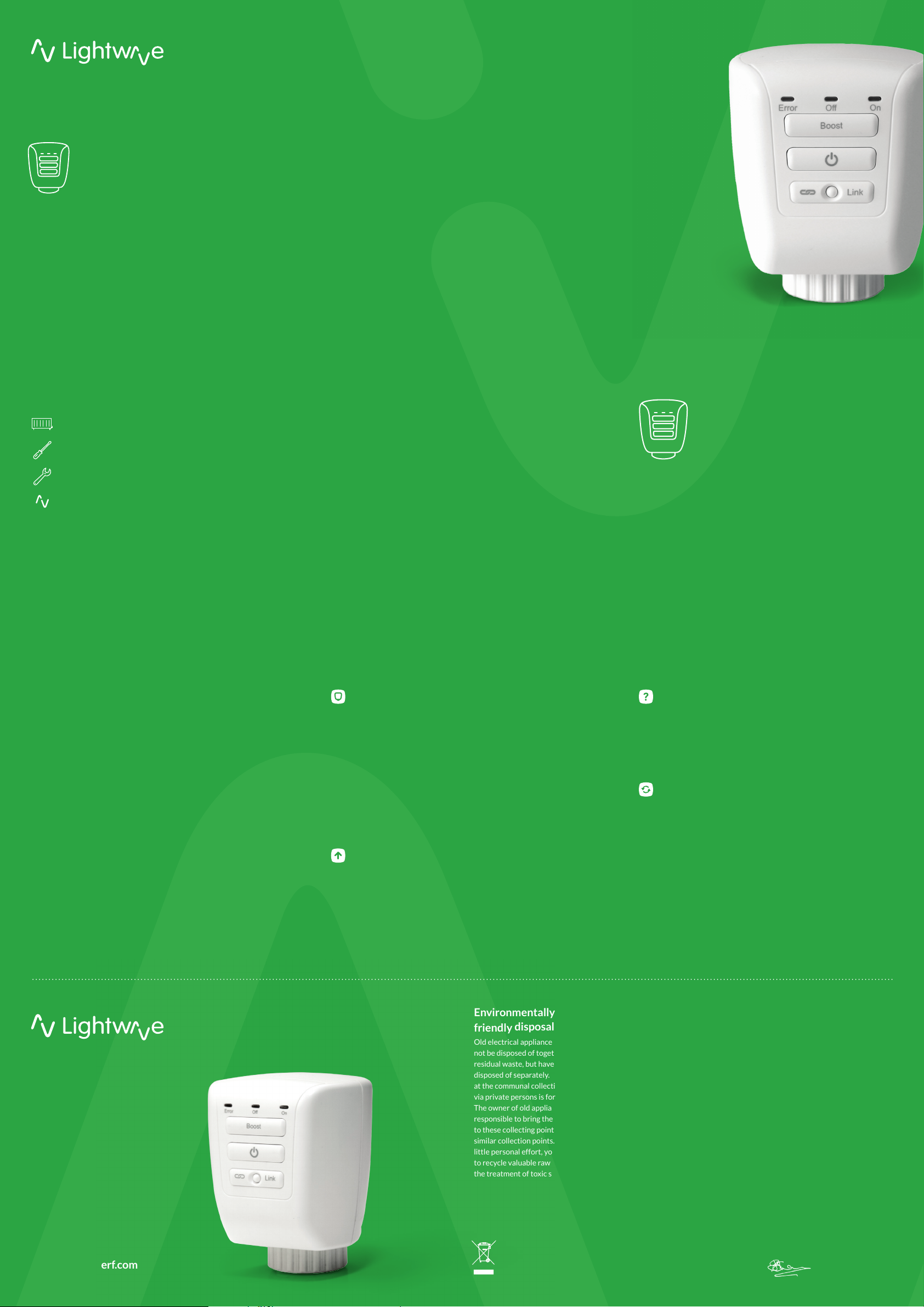
Environmentally
friendly
Old electrical appliances must
not be disposed of together with
residual waste, but have to be
disposed of separately. The disposal
at the communal collecting point
via private persons is for free.
The owner of old appliances is
responsible to bring the appliances
to these collecting points or to
similar collection points. With this
little personal effort, you contribute
to recycle valuable raw materials and
the treatment of toxic substances.
disposal
EC Declaration of Conformity
Responsible Authority:
LightwaveRF PLC,
Innovation Campus Birmingham
Faraday Wharf, Holt Street,
Birmingham, B7 4BB
Tel: +44 (0)121 250 3625
Email: enquiries@lightwaverf.com
Model Number(s): LW922
Description: Radiator Valve
Directives this equipment
complies with: 2006/95/EC,
The Low Voltage Directive,
N/. 2004/108/EEC, The
Electromagnetic Compatibility
Directive, 1999/5/EC R&TTE
Directive, 93/68/EEC CE
Marking Directive
Standards Applied in order to
verify compliance
Safety: BS EN 60730-1: 2011
Health: R&TTE: EN 301 489-1 V1.9.2:
(2011-09), EN 301 489-3 V1.4.1:
(2002-08), EN 300 220-1 V2.1.1:
2006, EN 300 220-2 V2.1.2: 2007,
EMC: EN 301 489-1 V1.9.2: (2011-09),
EN 301 489-3 V1.4.1: (2002-08), EN
55022: 2010, EN 61000-3-2: 2006
+A1: 2009 +A2: 2009 Class A, EN
61000-3-3: 2008, EN61000-4-2:
2009, EN 61000-4-3: 2006 +A1: 2008
+A2: 2010, EN 61000-4-4: 2012, EN
61000-4-5: 2006, EN 61000-4-6:
2009, EN 61000-4-11: 2004
For and on behalf of
LightwaveRF PLC
J Shermer,
CTO
Page 2
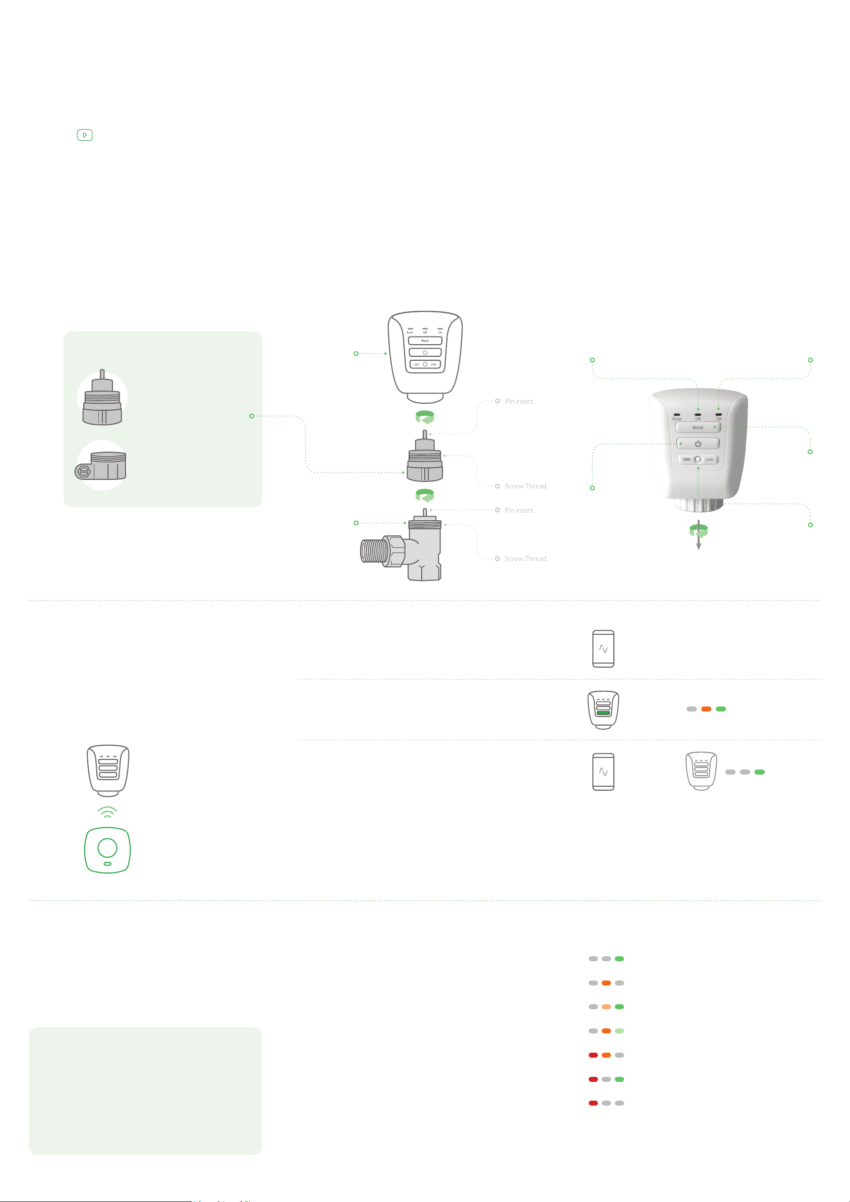
Pin insert.
Screw Thread.
Screw Thread.
Pin insert.
GETTING STARTED
1
Install the Valve
The easiest way to learn how to install
the Lightwave Valve is to watch our short
installation video which is accessible at
www.lightwaverf.com/product-manuals
Carefully follow the instructions in this section
in order to install the Lightwave Valve. Please
remember that live electricity is dangerous. Do not
take any risks. If in any doubt, consult a qualied
professional. For other advice, please contact our
dedicated technical support team on 0121 250 3625.
COLLAR TYPES
1.1 Removing the existing Radiator Valve
To attach the Lightwave Radiator Valve you will rst need to ensure that
you have a suitable thermostatic valve tted to your radiator (such as
the one pictured) and unscrew the existing valve head. This can usually
be done by hand and does not require any special tools. An adjustable
screw driver maybe useful if the valve head is tightly secured.
Note: Removing the existing valve head should not cause any water
leaks as the main body of the valve remains sealed
1.2 Screw t the Lightwave Radiator Valve
The Lightwave Radiator Valve will screw t the majority of existing
thermostatic valves without alterations. There are, however, several
adapter collars provided to compensate for the most typical variations
in the diameter of the valve and screw thread.
Valve Head.
There are 2 types of collar (type A, type B). If type A ts the valve
screw thread, this is the more desirable collar to use. It has 4
insert pin length options provided for the collar. The most suitable
pin is the one that (when in the collar) replicates the length of the
existing pin. Type B provides a clamp t around the valve body and
can be tightened using the screw provided.
1.3 Insert the batteries
The battery compartment is located at the top of the Lightwave
Valve. Remove the cover and insert 2x AA batteries. Once the
batteries are inserted, the Lightwave Valve will automatically
calibrate itself (this can take up to a minute). This requires it to be
attached to the radiator, therefore do not insert the batteries until
the Lightwave Valve is securely installed. If the ‘error’ LED lights
up during calibration, the radiator valve is not seated properly and
may need adjustment.
‘Off’ LED.
When illuminated the
TRV is closing.
When illuminated the
‘On’ LED.
TRV is opening.
2
Type A
With in pin inserted.
Type B
Without pin.
Link the Valve
To be able to command the Socket,
you will need to link it to the Link Plus.
Valve.
Please follow the in App instructions which will explain
how to link devices.
Standby button.
Turns radiator on
/ off.
Screw collar to attach to
radiator valve.
Boost button.
Increases the
temperature for
one hour.
Linking button.
Press to enter
linking mode.
Other Valve
3
Follow Lightwave
Visit www.lightwaverf.com to discover the latest
product updates and nd out what else you can do
with Lightwave products. You can also sign up to
our newsletter or keep up to date with the latest
updates and releases via Twitter and Facebook.
functions
When prompted, press and release the ‘Link’ button on the
Lightwave Valve (the on and off LEDs will ash alternately).
Send the linking command from the App (the in-App instructions
will explain how to do this). The ‘on’ LED should ash to indicate a
successful link.
The boost button
Pressing the boost button on the Lightwave Valve raises
the target temperature by a few degrees above the current
room temperature for the duration of one hour. If the target
temperature is already several degrees higher than the actual
room temperature, then pressing boost will simply match
this temperature.
The standby button
Pressing the ‘standby’ button on the Lightwave Valve toggles
between the fully open and fully closed positions for the duration
of one hour. This will turn the radiator on or off by enabling or
preventing the ow of hot water to it. When the ‘standby’ button
is pressed, a green light will illuminate to indicate that the valve
is opening, or an amber light will illuminate to indicate that the
valve is closing.
Press
Link
Understanding the indicator LEDs
Steady green ‘on’:
Radiator valve opening
Steady amber ‘off’:
Radiator valve is closing
Alternating on/off (longer on LED):
Linking mode
Alternating off/on (longer off LED):
Unlinking mode
Steady red & amber:
Valve jammed or wrong pin
Steady red & green:
Not mounted correctly / wrong pin
Flashing red:
Low battery (The App will also
report low battery status).
 Loading...