


www.lightwaverf.com
Get the best out of your install This Lightwave Smart Socket requires a 35mm deep back box
in which to mount it. If you have a back box that is shallower
than 35mm, then a Lightwave spacer can be used to provide
up to 10mm of extra clearance from the wall.
Back box and spacers
Model No. L42WH
Old electrical appliances must
not be disposed of together with
residual waste, but have to be
disposed of separately. The disposal
at the communal collecting point
via private persons is for free.
The owner of old appliances is
responsible to bring the appliances
to these collecting points or to
similar collection points. With this
little personal effort, you contribute
to recycle valuable raw materials and
the treatment of toxic substances.
Environmentally
friendly
disposal
Before you start
Hints and tips
A back-box with a minimum depth of 35mm
Suitable electrical screwdrivers
Knowledge of how to safely turn off/on
mains electricity
Lightwave Sockets should have an excellent communication
range within a typical home, however, if you encounter any
range issues, try to ensure that large metal objects or bodies
of water (e.g. radiator) are not positioned in front of the
socket or in between socket and the Lightwave Link Plus.
Range
Your Link Plus, smartphone and socket
You will need
Lightwave Smart Sockets can be locked from the Lightwave
App so that they cannot be operated manually. This is a great
way help with family safety by ensuring that dangerous
appliances cannot be turned on or off by small children.
Locking sockets
Using the Link Plus and Lightwave App, you can create
custom automations for Lightwave devices. Automations
provide a whole host of clever features, including timers,
group actions, triggers and wireless 2-way switching. Find out
more by exploring the Lightwave App.
Automations
In the box
L42 Socket
Socket spacer
RF frequency:
868 MHz
Input rating:
230V~ 50Hz.
Output rating:
3,000W max
Back Box Depth:
35mm min
Standby Energy Use:
Less than 1W (per gang)
Warranty:
2 year standard warranty
Specication
Let’s get started
Smart
Socket
Quick Start Guide
Installing yourself?
Please note that all Lightwave products can be legally
DIY installed in your own home; however, if in doubt,
always consult a qualied electrician.
It is important to install this product in accordance with
these instructions. Failure to do so may risk personal safety,
could create a re hazard and will also void your warranty.
If conducting an insulation resistance test, any hard-wired
Lightwave devices must be disconnected from the mains,
or damage to the unit may occur.
Help video & further guidance
For additional guidance, and to watch a video that will help
guide you through the installation process, please visit the
support section on www.lightwaverf.com
x2 Fixing screws
EU Declaration of Conformity
Product: Dual Mains Socket
Model/Type: L42
Manufacturer: LightwaveRF
Address: Innovation Campus
Birmingham, Faraday Wharf,
Holt Street, Birmingham, B7 4BB
This declaration is issued under
the sole responsibility of the
LighwaveRF. The object of the
declaration described above is in
conformity with the relevant union
harmonisation legislation.
Directive 2011/65/EU ROHS,
Directive 2014/53/EU: (The Radio
Equipment Directive)
Conformity is shown by
compliance with the applicable
requirements of the following
documents:
Reference and date:
EN301489-3 V1.6.1: (EMC),
EN300220-2 V3.1.1 (RF),
EN62479:2010 (RF Exposure),
EN60669-2-5:2013 (Safety),
BS1363-2:1995 (UK Safety)
Signed for and on behalf of:
Place of Issue: Birmingham
Date of Issue: 20th August 2017
Name: John Shermer
Position: CTO
Install the Socket
Carefully follow the instructions in this section in
order to install the Socket. Please remember that live
electricity is dangerous. Do not take any risks.
If in any doubt, consult a qualied professional.
For other advice, please contact our dedicated
technical support team on 0121 250 3625.
1
Link the Socket
2
The easiest way to learn how to install the
Lightwave Socket is to watch our short
installation video which is accessible at
Turn off the mains power supply to your existing power
circuit at the consumer unit.
1.1 Turn off the mains electricity supply
Unscrew the existing socket and remove the wires. It is often a
good idea to take a quick photo of the existing wiring conguration.
This can help you to remember which wires connect to which
terminals if there are more than two, or if they are not distinctly
labelled. The existing wiring should be colour coded and arranged
as per the wiring diagram provided in these instructions, however,
please be aware that not all existing wiring will conform to this
standard and may differ.
1.2 Remove the existing socket
Remove the faceplate from the Lightwave Socket by
carefully inserting a screwdriver into the small slot
located at the bottom edge of the cover.
1.3 Remove the faceplate
Carefully wire the socket as shown in the
diagram. Be aware that existing cables
can vary in colour and may not always be
correctly labelled. If in any doubt, always
consult a qualied electrician. Replace the
faceplate by hooking it onto the top edge of
the Socket and clipping in the bottom.
1.4 Wire the socket
To be able to command the Socket,
you will need to link it to the Link Plus.
Please follow the in-app instructions which will explain
how to link devices.
On the Socket, press and hold down one of the ‘on’ / ‘off’ buttons
until the LED ashes blue and red alternately then release it.
The Socket is now in linking mode.
Using the Lightwave App, press the button you want to link to (the
App instructions will guide you through this). The blue light on the
Socket switch will ash to conrm that it is now linked to the App.
Other Socket
functions
3
Unlinking the Socket (clear memory)
To unlink the Socket and clear the memory, enter linking mode by
holding down the on/off button until the LED ashes red. Release
the button, then hold it for a second time until the LED ashes red
to conrm that the memory has been cleared.
Locking the Socket
The Socket can be ‘locked’ using the App so that the manual
buttons will not operate it. If it is locked on, then the Socket will
not turn off manually. A locked socket is signied by a slow ashing
magenta LED. To lock / unlock the Socket, press the ‘lock’ button
on the Smartphone App. Clearing the memory will remove the
lock.
Changing the colour of the indicator LED
The colour of the LED indicator lights on the socket can be
changed or the LED turned off using the Lightwave App. See the
App for more details.
Firmware updates
Firmware updates are over-the-air software improvements that
keep your device up to date as well as providing new features.
Updates can be approved from the App before being implemented,
and generally take 2-5 minutes. The LED will ash cyan in colour
during an update. Please do not interrupt the process during this
time.
Error reporting
A permanently ashing red LED indicates that a software or
hardware error has been encountered. Press the on/off button to
reset the indicator LED. If the error light persists, please contact
Lightwave support via www.lightwaverf.com/support.
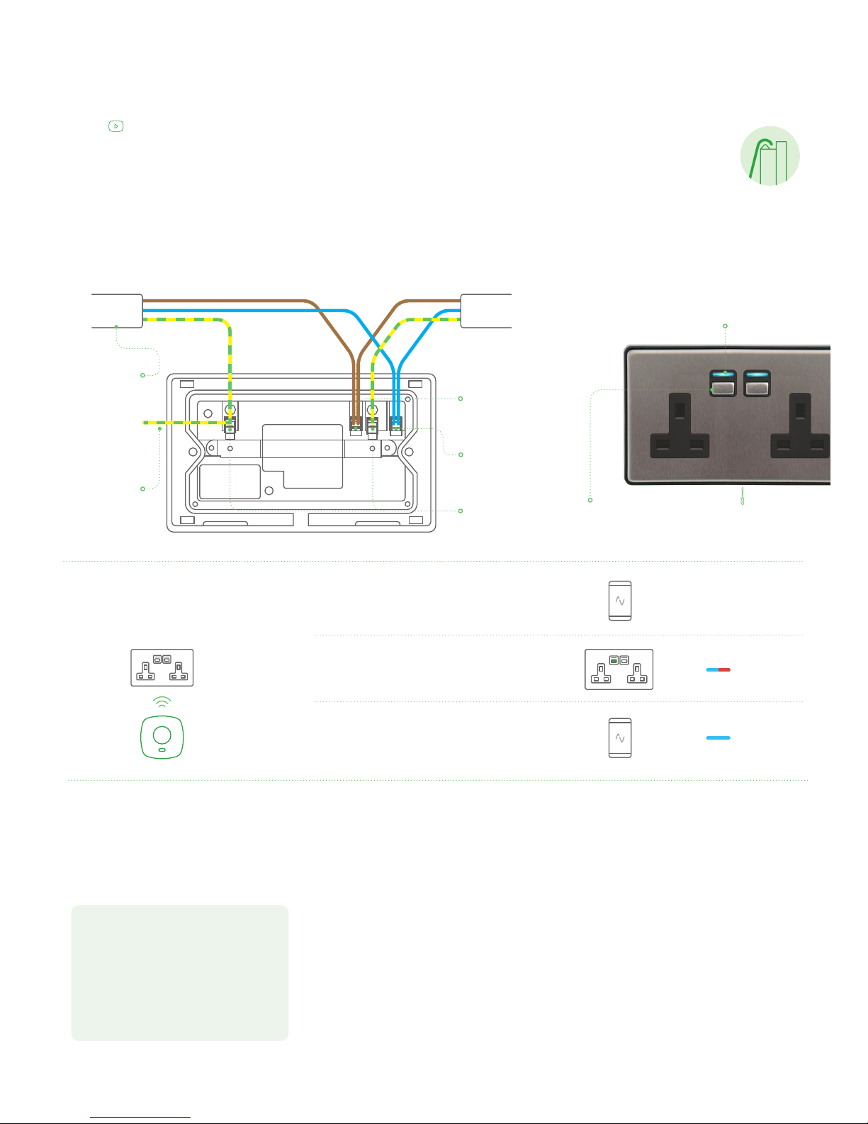
Earth wire this should
also be connected to earth
terminal in the back box if
one exists (important when
using metal back boxes).
Main circuit cable.
entering and leaving
back box.
Earth wire connections.
Neutral wire connection.
The wires should be blue
or black in colour.
www.lightwaverf.com/product-manuals
On / Off button.
Press to turn on / off.
LED.
Indicator.
Screwdriver slot.
To remove the cover plate.
Live wire connection.
The wires should be
brown or red in colour.
Circuit cable
Circuit cable
GETTING STARTED
Hold
Visit www.lightwaverf.com to discover the latest
product updates and nd out what else you can do
with Lightwave products.
For advice, troubleshooting and technical support,
please see www.lightwaverf.com/support
Follow Lightwave
Note: The Socket LED will ash on detecting the
insertion or removal of a mains plug.
 Loading...