

EasyCheck Integrated Fiber Optic End-face Inspector
EC400KC
EC200KC
EC080KC
INSTRUCTION MANUAL
© Copyright 2013 Tactical Deployment Systems LLC
Additional information on this product can be found at our website.
http://www.lightwavecable.com/
Introduction
Endface Inspector
Operation
Maintenance

TABLE OF CONTENTS
I II
Chapter 1 | Introduction 1
Durability & Value 1
Design Concept 1
Unrivaled Image Quality 2
Convenience 2
Dust-Proof 2
Centered Image 3
Precision Ceramic Adaptor Tips 3
Safe & Ergonomic Design 3
Image Storage 3
Technical Specifications 4
Included Items 4
Chapter 2 | Function Keys Instruction 5
Front View Diagram 6
Focusing System Diagram 6
Rear View Diagram 7
SD Card Port Diagram 7
Focusing System Use Diagram 8
Chapter 3 | Operation Instructions 9
Installation 9
Adapter Tip Installation 9
Machine Adjustment 9
Brightness & Contrast Adjustment 10
Image Capture 11
Inspections 11
Picture View 11
External Monitor Instructions 11
External Optical Fiber End-face Inspector Instructions 12
Chapter 4 | Maintenance 12
Notice 12
Maintenance 12
TABLE OF CONTENTS
1 2
LightWave EasyCheck Fiber Optic End-face Inspector LightWave EasyCheck Fiber Optic End-face Inspector
Chapter 1 | Introduction
Thank you for purchasing your new LightWave EasyCheck Optical End-face Inspection
System. We are confident it will provide you with years of superb service, reliability, and
accuracy.
The EasyCheck EC400KC features a continuous variable zoom ratio, manual focusing, X and
Y-axis adjustable function and 400x, 200x or 80x zoom capability.
EasyCheck combines a compact design with enhanced functionality. Replacing the
traditional combination of a microscope and monitor, users can simply connect power and
begin operation. EasyCheck helps you save time and space, and improve productivity.
Advanced coaxial illumination permits easy detection of fine defects on the end-face of the
fiber connector. The conjunction with a dust-proof, high-resolution image sensor, an 8"
black-and-white digital TFT display clearly shows all details of the fiber end-face.
EasyCheck is equipped with 1.25mm and 2.5mm ceramic precision tips that meet most
inspection requirements. The high concentricity provides an ideally centered image when
installing different tips. The ceramic casing tips have nearly infinite life and the image will not
deviate from center due to extended use. The fiber End-face image can be captured at any
time and stored on a standard SD flash memory card.
Durability & Value
Durability is one of the most important factors to consider when evaluating inspection
equipment. Every EasyCheck unit and component comes from considerable design and
selection processes. The outstanding performance makes inspection a pleasure and the low
price and low failure rate give users real benefits.
Design Concept
Easycheck combines the compact appearance with enhanced functionality. Integrated
design results in smaller size and more convenient operation. Users simply connect the power
cable to the unit to start inspections. You no longer need to worry about the complicated cable
between monitor and microscope. Easycheck helps you save time and space, and improve
productivity.
Unrivaled Image Quality
The optical amplification system for coaxial illumination makes even the finest defects in the
endface of fiber connector clearly visible. The high-resolution image sensor, along with 8"
black-and-white digital TFT display clearly shows all details of the fiber endface, ensuring
reliability of inspection results.
Convenience
Our engineers designed the focus ring on the EasyCheck for smooth focusing. External
adapter tips make inspections of numerous connector types quick and simple.
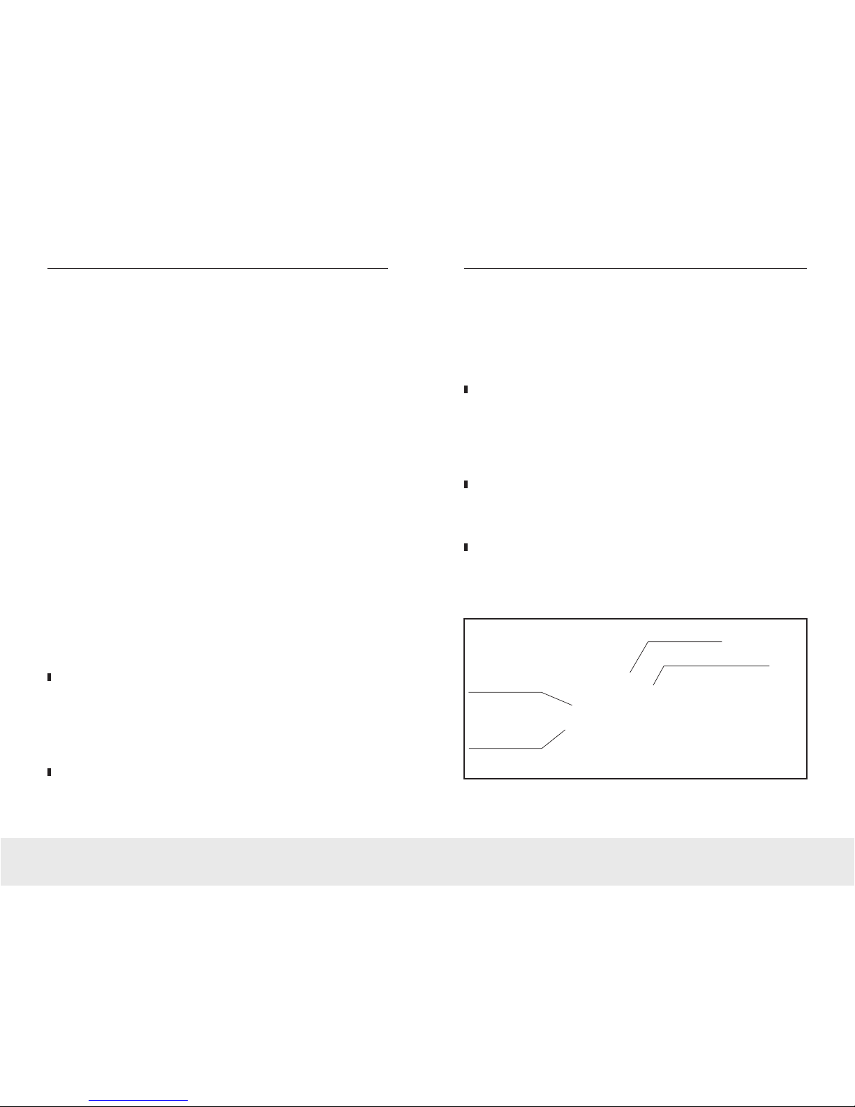
Dust-proof
Dustproofing has been incorporated within the focusing system. Even working in dirty
environments will not affect the focus performance.
Focus Ring
Dust-Proof Cover
External Adapter Tip
Precise Optical-Mechanical
Alignment Structure

3 4
LightWave EasyCheck Fiber Optic End-face Inspector LightWave EasyCheck Fiber Optic End-face Inspector
Centered Image
EasyCheck’s intelligent optoelectronic structure and adaptor tips always keep the image in
the center during focusing, eliminating image jitter problems.
Precision Ceramic Adaptor Tips
EasyCheck comes with 1.25mm and 2.5mm ceramic precision tips that meet various
inspection requirements. The high-level concentricity provides an ideally centered image
when installing different tips. The ceramic casing tips have infinite lifespan and the image will
not deviate from center due to extended use.
Safe & Ergonomic Design
Easycheck features a customized 8" digital TFT monitor to reveal the subtle defects of the
fiber end-face. Compared with traditional CRT monitor, the digital TFT monitor has no screen
flashing.
Image Storage
The fiber end-face image can be captured at any time and be stored on the included SD card,
making it easier for volume production, standard settings, and failure analysis.
Ceramic-Inlaid Sleeve Adapter Tips
Model Number
Amplification Factor
X / Y Axis Adjustment
Image Input/Output Format
CCD Areal Resolution
Image Output Tip
Image Input Tip
Focus Mode
Image Analysis
Power Dissipation
Working Temperature
Storage Temperature
Display
Power Supply
Volume
Weight
EC400KC EC200KC EC200KC
400x 200x 80x
Yes
Simulated PAL
1/3” 420cable
RCA
RCA
Manual
None
3W
+50°F ~ +122°F
32°F ~ +131°F
8” TFT 800x600 PIX
DC 12
270mm x 245mm x 155mm
3.5 lbs.
EasyCheck Technical Specifications
Included Items:
•
EasyCheck Fiber Optic End-face Inspector
•
2.5mm Tip and 1.25mm Tip
•
2G SD Storage Card
•
Main DC 12V Power Supply
•
Instruction Book
NOTE: Choose appropriate power adapter according to location standards and appropriate tip according to connector requirements.

5 6
LightWave EasyCheck Fiber Optic End-face Inspector LightWave EasyCheck Fiber Optic End-face Inspector
Chapter 2 | Function Keys Instruction
The EasyCheck Fiber End-face Inspector features a continuous variable zoom ratio, manual
focusing, X- and Y-axis adjustable function and 400x, 200x or 80x zoom capability. Utlilizing
different inspection tips, EasyCheck can fulfill various inspections of fiber connectors
(including MPO/MTP, MT-RJ multi channel connector), optical transceivers and TOSA/ROSA
components. All the tips are external and easily interchangeable.
TOSA/ROSA Component Inspection
TOSA/ROSA Component Inspection
Multi-Channel Inspection
EasyCheck Function Description
3 4 5 6 7
2
1
1 - Focusing System
2 - Power Indicator Line
3 - High-resolution Screen
4 - MENU Button
5 - Page Up Button
6 - Page Down Button
7 - Image Capture Button
8 - Adapter Tip
9 - Dust Covers
10 - Focusing Ring
8 9 10

7 8
LightWave EasyCheck Fiber Optic End-face Inspector LightWave EasyCheck Fiber Optic End-face Inspector
EasyCheck Function Description (cont’d)
11 - Power Switch
12 - 12V Power Supply Port
13 - A/V Image Output Port
14 - Image Display Switch
15 - USB Image Input Port
16 - A/V Image Input Port
17 - SD Card Slot
Notes: (14) External display devices can be connected to present internal video signal.
(15) Used for switching between internal and external signal source.
(16 & 17) Dedicated image input tip for external endface inspectors.
17
11 12 13 14 15 16
EasyCheck Function Description (cont’d)
The EasyCheck can be utilized for single-channel and multi-channel connector inspections.
Combining aesthetics and practicability, EasyCheck subverted the traditional design concept
and makes the process of inspection not only valuable but also enjoyable.
1 - Focus Ring
2 - Dust Cover
3 - Fiber Cavity
4 - Connector Adaptor Tip
5 - Locking Screw (For multi-channel connector inspections only)
6 - Y-Axis Image Adjustment Screw (+2mm ~ -2mm Adjustment Range)
7 - X-Axis Image Adjustment Screw (+2mm ~ -2mm Adjustment Range)
12354
6 7
9 10
LightWave EasyCheck Fiber Optic End-face Inspector LightWave EasyCheck Fiber Optic End-face Inspector
Chapter 3 | Operation Instructions
Installation
Open box and take out the machine, choose and install the corresponding adapter tip into
Easycheck (the tip should be fastened securely). Assemble the power adapter and power line
and makes sure the power supply is well connected.
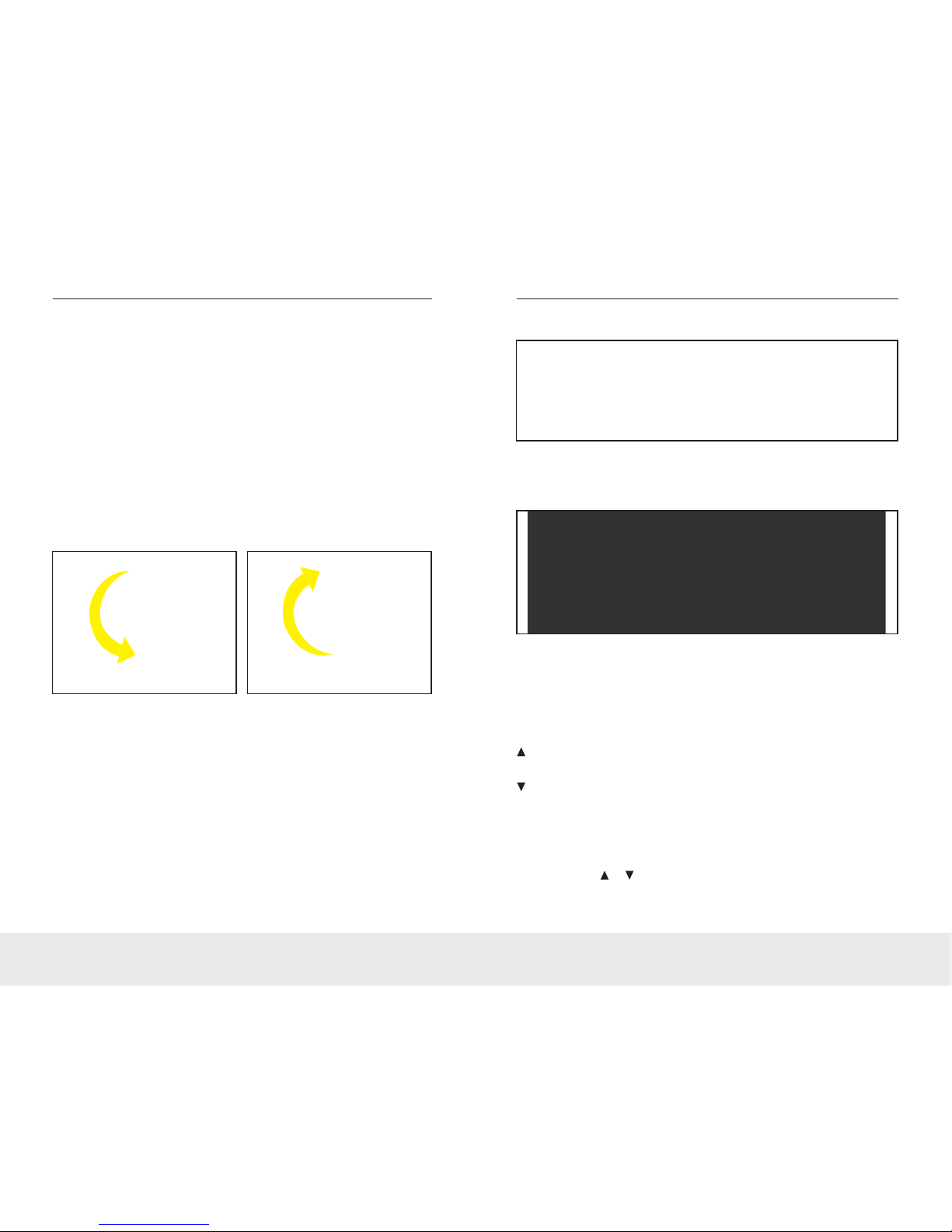
Adapter Tip Installation
EasyCheck provides different adaptor tips to fulfill various connector inspection needs. Screw
counter-clockwise to remove the adaptor tip. Select the needed tip, match the threads of tips
and screw in clockwise tightly.
Machine Adjustment
Power on and insert the optical fiber connector into the EasyCheck adaptor tip. Adjusting the
focus ring clockwise, the connector moves away from inspector body; adjusting the focus
ring counter-clockwise, the connector moves towards the inspector body. To observe the
fiber end-face, adjust the focus ring until image gets clear and bright. Make sure the image
display switch is turned to the right in this mode.
Sometimes adjustment is required to optimize the inspection result depending on different
situations.
Adaptor Tip Removal Adaptor Tip Attachment
Brightness & Contrast Adjustment
Press MENU to enter the brightness and contrast adjustment interface, as shown below:
In this adjustment interface:
MENU: Page Down key, can choose downward from BRIGHTNESS, CONTRAST to EXIT,
selected one is shown in black;
CAP: Page Up key, can choose upward from EXIT, CONTRAST TO BRIGHTNESS, selected
one is shown in black;
: Up key, can raise the value of BRIGHTNESS and CONTRAST; selecting EXIT means
save and exit the interface.
: Down key, can reduce the value of BRIGHTNESS and CONTRAST; selecting EXIT
saves and exits the interface
Adjust the BRIGHTNESS and CONTRAST according to specific requirements. When the
BRTIGHTNESS and CONTRAST is set at the optimum value, press MENU to select the EXIT
column, then press or to save settings and start inspection.

11 12
LightWave EasyCheck Fiber Optic End-face Inspector LightWave EasyCheck Fiber Optic End-face Inspector
Image Capture
CAP is the image capture key. Pressing CAP can capture and save the current image to the
SD card. The screenshot can only be accessed with the SD card inserted. Power must be
switched off before insertion and removal of the SD card.
Inspections
After adjustment, connect the product to be tested onto the adaptor tip and adjust the focus
ring to get the clear image. Spin the X-axis screw clockwise, connector moves towards the
left; spin the X-axis screw counterclockwise, connector moves towards the right; spin the
Y-axis screw clockwise, connector moves upwards; spin the Y-axis screw counterclockwise,
connector moves downwards; users can view the entire surface condition with the help of XY
axis screws.If polishing is required, press CAP during inspection and the image captured will
be kept on file in SD card. Power off the inspector, pull out SD card and reinsert into
computer.
Picture View
Press to enter the picture view mode. Images stored in SD card can be viewed in this
mode. Press MENU to exit.
CAP: Delete: pressed the first time, DEL? prompt is displayed; Press again to delete the
current image.
: Up key, View the previous image.
: Down key, View the next image.
External Monitor Instructions
In this mode, images can be viewed simultaneously from the external monitor and the
EasyCheck’s 8" display. Connect the external monitor to EasyCheck’s AV OUT port tip with AV
video cable. Turn on the EasyCheck and the external monitor. Connect the simplex or multi-
channel optical fiber connector with the EasyCheck and adjust the focusing ring to get a clear
image. The end-face status can then be viewed from both displays. Make sure the image
display switch is turned to the right in this mode.
External Optical Fiber End-face Inspector Instructions
Easycheck’s has two AV IN port types: USB and AV. The USB type is customized for external
end-face inspectors. Connect external end-face inspector and EasyCheck and make sure the
EasyCheck’s image display switch is turned to the left. Power on the Easycheck and connect
the fiber connector to the external end-face inspector. Adjust the Easyget's focus ring to get
the clear image so as to observe the end-face condition.
RCA version has general image input tip for all types of end-face inspectors. Connect
inspector with EasyCheck and make sure the image display switch is turned to the left. Power
on the Easycheck and connect the fiber connector to the general inspector. Adjust the focus
ring to get the clear image so as to observe the endface condition.
Chapter 4 | Maintenance
Notice
1. Instruments must be moved gently.
2. No extrusion.
3. Power must be switched off when taking out SD card.
4. Use the Dimension Technology customized 12V DC power adapter. Other power
adapters are not allowed.
5. Do NOT disassemble instrument so as to avoid unnecessary loss.
6. Keep instrument away from sharps so as to avoid scratches on the screen.
Maintenance
1. Keep Easy check clean, away from grease and dust.
2. It would be better kept in the instrument container if the inspector will not be used for
a long time.
 Loading...