

Page 1

UMX-TP-TX100R
Programmer’s Reference Manual
Page 2

Page 3

UMX-TP-TX100R
Programmer’s Reference Manual
Page 3 / 43
SAFETY INSTRUCTIONS
Class II apparatus construction.
This equipment should be operated only from the power source indicated
on the product.
To disconnect the equipment safely from power, remove the power cord
from the rear of the equipment, or from the power source. The MAINS plug
is used as the disconnect device, the disconnect device shall remain
readily operable.
There are no user-serviceable parts inside of the unit. Removal of the top
cover will expose dangerous voltages. To avoid personal injury, do not
remove the top cover. Do not operate the unit without the cover installed.
The apparatus shall not be exposed to dripping or splashing and that no
objects filled with liquids, such as vases, shall be placed on the apparatus.
The apparatus must be safely connected to multimedia systems. Follow
instructions described in this manual.
WEEE (Waste Electrical & Electronic Equipment)
Correct Disposal of This Product
This marking shown on the product or its literature, indicates that it should
not be disposed with other household wastes at the end of its working life.
To prevent possible harm to the environment or human health from
uncontrolled waste disposal, please separate this from other types of
wastes and recycle it responsibly to promote the sustainable reuse of
material resources.
Household users should contact either the retailer where they purchased
this product, or their local government office, for details of where and how
they can take this item for environmentally safe recycling.
Business users should contact their supplier and check the terms and conditions of the
purchase contract. This product should not be mixed with other commercial wastes for
disposal.
Page 4

Page 4 / 43
DECLARATION OF CONFORMITY
We,
Lightware Kft. 15 Peterdy Street, Budapest H-1071, HUNGARY
as manufacturer declare, that the product
UMX-TP-TX100R
( Computer Monitor Extender )
in accordance with the EMC Directive 2004/108/EC and the Low Voltage Directive
2006/95/EEC is in conformity with the following standards:
EMI/EMC ..................................... EN 55022 Class B
Safety ........... UL, CUL, GS, CR, RCM, PSE, Class II
Date: 12 April 2012
Name: Gergely Vida (Managing Director)
Signed:
Page 5

UMX-TP-TX100R
Programmer’s Reference Manual
Page 5 / 43
Table of contents
1. ELECTRICAL CONNECTIONS ................................................................................................................ 7
1.1. HDMI INPUT ........................................................................................................................................ 7
1.2. VGA INPUT .......................................................................................................................................... 7
1.3. DIGITAL AUDIO INPUT CONNECTOR ........................................................................................................ 8
1.4. ANALOG STEREO AUDIO INPUT CONNECTORS ......................................................................................... 8
1.5. TWISTED PAIR OUTPUTS ....................................................................................................................... 9
1.6. RS-232 CONTROL PORT ..................................................................................................................... 10
2. ABOUT EDID MEMORY ........................................................................................................................ 11
2.1. EDID TYPES ...................................................................................................................................... 11
2.2. FACTORY EDID LIST .......................................................................................................................... 12
3. OPERATION MODES ............................................................................................................................ 12
4. PROGRAMMERS REFERENCE............................................................................................................ 14
4.1. SERIAL PORT SETTINGS ...................................................................................................................... 14
4.2. PROTOCOL DESCRIPTION .................................................................................................................... 14
4.3. STATUS AND IDENTIFICATION COMMANDS ............................................................................................ 15
4.3.1. View product type .................................................................................................................... 15
4.3.2. View serial number .................................................................................................................. 15
4.3.3. View Firmware version of the CPU .......................................................................................... 15
4.3.4. View installed controllers’ firmware.......................................................................................... 15
4.3.5. View device’s temperature ....................................................................................................... 15
4.3.6. View CPU firmware compile time ............................................................................................ 16
4.3.7. View installed I/O boards ......................................................................................................... 16
4.4. SYSTEM COMMANDS ........................................................................................................................... 16
4.4.1. Query current control protocol ................................................................................................. 16
4.4.2. Change RS-232 baud rate ....................................................................................................... 17
4.4.3. Query RS-232 baud rate .......................................................................................................... 17
4.4.4. Reload factory defaults ............................................................................................................ 17
4.4.5. Set the RS232 operation mode ............................................................................................... 18
4.4.6. Query the RS232 operation mode ........................................................................................... 18
4.4.7. Count HDCP keys .................................................................................................................... 18
4.4.8. Clear HDCP key cache ............................................................................................................ 18
4.4.9. Restart matrix router ................................................................................................................ 19
4.4.10. View error list ........................................................................................................................... 19
4.4.11. Configure remote alerts ........................................................................................................... 20
4.4.12. Query level of remote alerts ..................................................................................................... 20
4.4.13. Set the priority settings ............................................................................................................ 20
4.4.14. Query the priority settings ........................................................................................................ 21
4.5. EDID ROUTER COMMANDS ................................................................................................................. 21
4.5.1. Save EDID to user memory (Learn EDID) ............................................................................... 21
4.5.2. View emulated EDIDs on all inputs.......................................................................................... 21
4.5.3. Watch EDID validity table ........................................................................................................ 22
4.5.4. View EDID header ................................................................................................................... 22
4.5.5. Download EDID content from the router .................................................................................. 23
4.5.6. Upload EDID content to the router .......................................................................................... 23
4.5.7. Delete EDID from memory ....................................................................................................... 24
4.6. CONTROL COMMANDS ........................................................................................................................ 24
4.6.1. Switch one input to one output ................................................................................................ 25
4.6.2. View video connection on the output ....................................................................................... 25
4.6.3. View all connections on the output .......................................................................................... 25
4.6.4. Rename an input ..................................................................................................................... 26
4.6.5. Rename the output .................................................................................................................. 26
4.6.6. Read an input’s name .............................................................................................................. 26
4.6.7. Read the output’s name ........................................................................................................... 26
4.6.8. Reload default input names ..................................................................................................... 26
4.6.9. Reload default output name ..................................................................................................... 27
Page 6

Page 6 / 43
4.7. PORT STATUS COMMANDS .................................................................................................................. 27
4.7.1. Input port status ....................................................................................................................... 27
4.7.2. Output port status .................................................................................................................... 27
4.7.3. All port status ........................................................................................................................... 27
4.8. INPUT PROPERTIES ............................................................................................................................. 28
4.8.1. Set input port properties .......................................................................................................... 28
4.8.2. Query input port properties ...................................................................................................... 30
4.8.3. Set analog timing properties .................................................................................................... 31
4.8.4. Query analog timing properties................................................................................................ 31
4.8.5. Reset analog timing properties ................................................................................................ 31
4.8.6. Set analog color properties ...................................................................................................... 32
4.8.7. Save analog color properties ................................................................................................... 32
4.8.8. Query analog color properties ................................................................................................. 33
4.8.9. Reset analog color properties .................................................................................................. 33
4.8.10. Set analog input audio parameters .......................................................................................... 33
4.8.11. Query analog input audio properties ....................................................................................... 34
4.8.12. Set the color of no sync picture ............................................................................................... 34
4.8.13. Query the color of no sync picture ........................................................................................... 34
4.8.14. Query timings of the incoming signal ....................................................................................... 35
4.8.15. Save preset .............................................................................................................................. 35
4.8.16. Delete preset............................................................................................................................ 35
4.8.17. Delete all presets ..................................................................................................................... 36
4.8.18. Clone preset............................................................................................................................. 36
4.8.19. List presets ............................................................................................................................... 36
4.8.20. Delete preset from all input ports ............................................................................................. 37
4.9. OUTPUT PROPERTIES ......................................................................................................................... 37
4.9.1. Set output video properties ...................................................................................................... 37
4.9.2. Query output video properties ................................................................................................. 39
4.10. ERROR RESPONSES ........................................................................................................................... 39
5. COMMANDS – QUICK SUMMARY ....................................................................................................... 40
6. VERSION APPLICABILITY .................................................................................................................... 43
7. WARRANTY ........................................................................................................................................... 43
8. DOCUMENT REVISION HISTORY ........................................................................................................ 43
Page 7
UMX-TP-TX100R
Programmer’s Reference Manual
Section 1. Electrical connections Page 7 / 43
1. Electrical connections
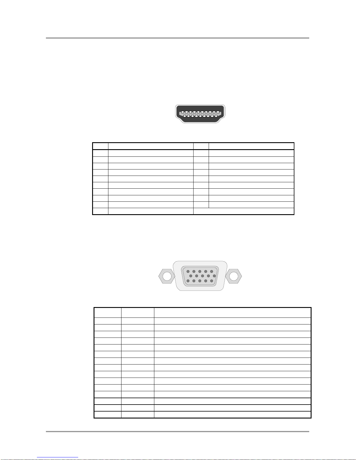
1.1. HDMI Input
UMX-TP-TX100R provides standard 19 pole HDMI connector for inputs. Always use high
quality HDMI cable for connecting sources and displays.
HDMI Type A receptacle
Pin
Signal
Pin
Signal
1
TMDS Data2+
11
TMDS Clock Shield
2
TMDS Data2 Shield
12
TMDS Clock–
3
TMDS Data2–
13
CEC
4
TMDS Data1+
14
Reserved
5
TMDS Data1 Shield
15
SCL
6
TMDS Data1–
16
SDA
7
TMDS Data0+
17
DDC/CEC/HEC Ground
8
TMDS Data0 Shield
18
+5 V Power (max 50 mA)
9
TMDS Data0–
19
Hot Plug Detect
10
TMDS Clock+
Table 1-1. HDMI connector pin assignments
1.2. VGA Input
UMX-TP-TX100R provides standard 15 pole D-SUB female connector for VGA inputs.
Always use high quality VGA cable for connecting sources and displays.
Figure 1-1. D-SUB 15 pole female connector (DE15F)
Pin nr.
Name
Description
1
RED
Red Video (75 ohm, 0.7 V p-p)
2
GREEN
Green Video (75 ohm, 0.7 V p-p)
3
BLUE
Blue Video (75 ohm, 0.7 V p-p)
4
ID2
Monitor ID Bit (Not used, internally connected to Pin 5)
5
GND
Ground
6
RGND
Red Ground (Internally connected to Pin 5)
7
GGND
Green Ground (Internally connected to Pin 5)
8
BGND
Blue Ground (Internally connected to Pin 5)
9
KEY
Optional +5V output from graphics card
10
SGND
Sync Ground (Internally connected to Pin 5)
11
ID0
Monitor ID Bit 0 (Not used, internally connected to Pin 5)
12
SDA
I2C bidirectional data line
13
HSYNC
Horizontal Sync
14
VSYNC
Vertical Sync which works also as data clock
15
SCL
I2C data clock in DDC2
Table 1-2. D-sub connector pin assignment for standard VGA
1 2 3 4 5 6 7
8
9
10
11
12
13
14
15
16
17
18
19
1 5 11
10
6
15
Page 8
Page 8 / 43 Section 1. Electrical connections
1.3. Digital audio input connector
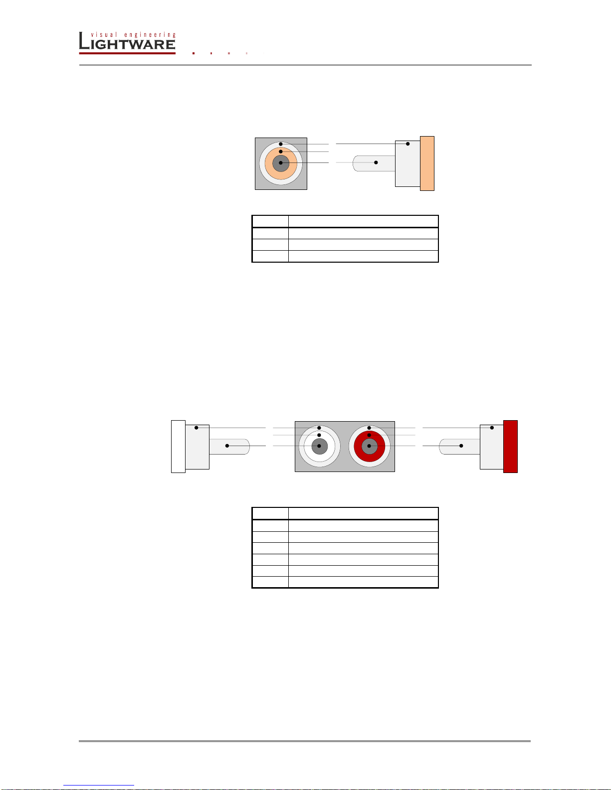
UMX-TP-TX100R has standard RCA receptacles for digital coaxial audio input.
RCA receptacle RCA plug
Nr.
Name
1
S/PDIF input or output
2
Plastic insulator
3
GND
Table 1-3. RCA connector pin assignments for digital audio
Info: Plugs and sockets on consumer equipment are conventionally color-coded by
CEA/CEDIA-863-B (ANSI) to aid correct connections. According to the standard
Lightware uses orange colored RCA connectors for S/PDIF signals.
1.4. Analog stereo audio input connectors
UMX-TP-TX100R has standard RCA receptacle for analog stereo audio input. Input
works with standard line-in voltage levels.
RCA plug (left channel) RCA receptacles RCA plug (right channel)
Nr.
Name
1
Right channel input or output
2
Plastic insulator
3
GND
4
Left channel input or output
5
Plastic insulator
6
GND
Table 1-4. RCA connector pin assignments for analog audio
Info: Plugs and sockets on consumer equipment are conventionally color-coded by
CEA/CEDIA-863-B (ANSI) to aid correct connections. According to the standard
Lightware uses red colored RCA connectors for right channel of analog stereo audio
signals and white colored RCA connectors for left channel of analog stereo audio signals.
000
0
3
2
1
0000 000
0
3
2
1
6
5
4
Page 9
UMX-TP-TX100R
Programmer’s Reference Manual
Section 1. Electrical connections Page 9 / 43
1.5. Twisted Pair outputs
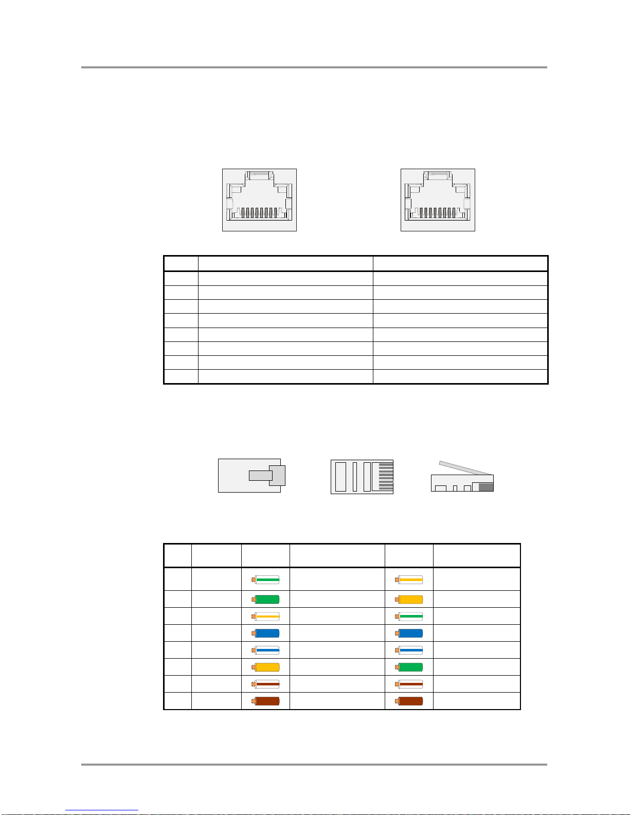
UMX-TP-TX100R provides standard RJ-45 connectors for VIDEO OUT and DDC OUT.
VIDEO DDC
RJ45 receptacle RJ45 receptacle
Pin
VIDEO OUT
DDC OUT
1
TMDS Data0+
CEC (out)
2
TMDS Data0-
Hot Plug Detect (out)
3
TMDS Clock+
RS-232 RX
4
TMDS Data1+
DDC CLK
5
TMDS Data1-
+12V (out)
6
TMDS Clock-
RS-232 TX
7
TMDS Data2+
DDC SDA
8
TMDS Data2-
GND
Table 1-5. RJ45 input and output connector pin assignment
Warning: Avoid interchanging the connection to the VIDEO and DDC lines!
Wiring of RJ45 plugs
Lightware recommends the termination of TP cables on the basis of TIA/EIA T 568 A or
TIA/EIA T 568 B standards.
Pin
Name
TIA/EIA
T568 A
color and
name
TIA/EIA
T568 B
color
and name
1
TX +
white/green stripe
white/orange
stripe
2
TX - green solid
orange solid
3
RX +
white/orange stripe
white/green stripe
4
Not used blue solid
blue solid
5
Not used
white/blue stripe
white/blue stripe
6
RX - orange solid
green solid
7
Not used
white/brown stripe
white/brown stripe
8
Not used
brown solid
brown solid
Table 1-6. Recommended termination of TP cables
1
8
1
8 1
8 1
Page 10
Page 10 / 43 Section 1. Electrical connections
1.6. RS-232 control port
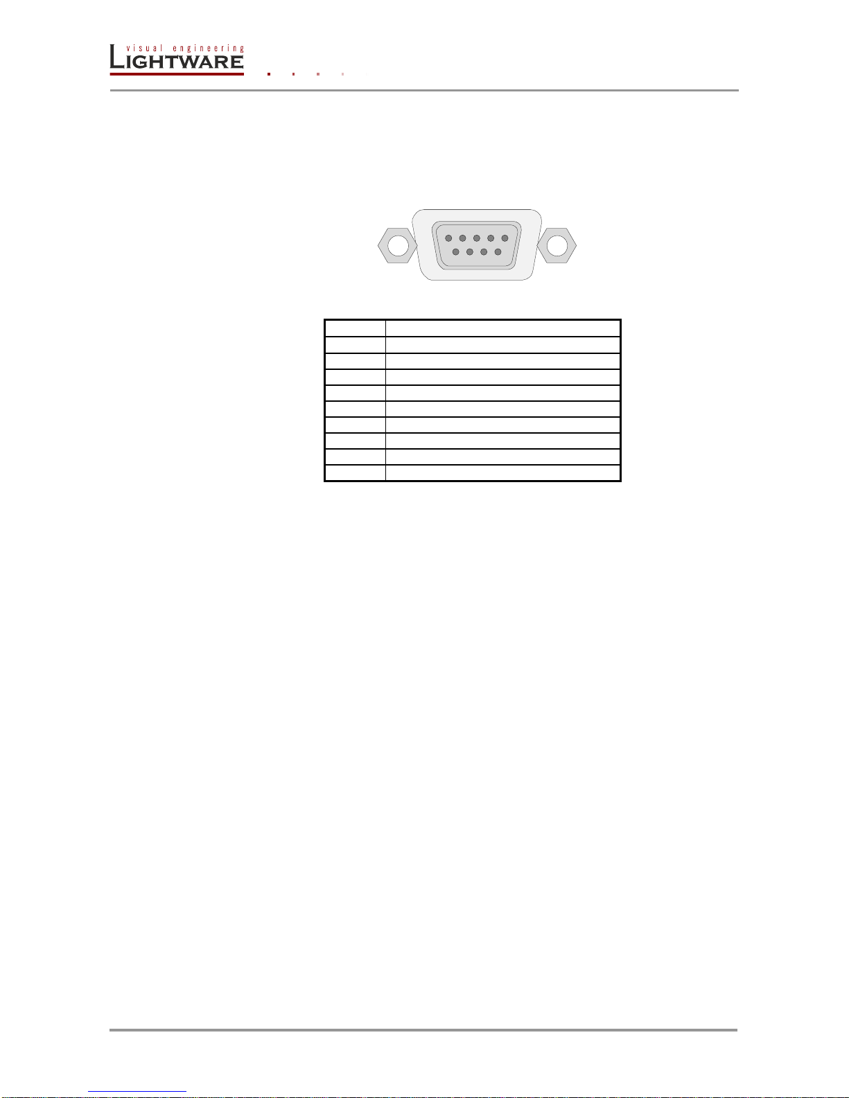
UMX-TP-TX100R can be remote controlled through industry standard 9 pole D-SUB
female connector. The extender uses RS 232 control port.
Figure 1-2. D-SUB 9 pole female connector (DE9F)
Pin nr.
RS-232
1
NC - non connected
2
TX data transmit (output)
3
RX data receive (input)
4
DTR (Internally connected to Pin 6)
5
GND signal ground (shield)
6
DSR (Internally connected to Pin 4)
7
RTS (Internally connected to Pin 8)
8
CTS (Internally connected to Pin 7)
9
NC - non connected
Table 1-7. D-sub connector pin assignment for standard RS-232
1
5
6
9
Page 11

UMX-TP-TX100R
Programmer’s Reference Manual
Section 2. About EDID memory Page 11 / 43
2. About EDID memory
EDID memory is non-volatile and consists of four blocks, each for different purpose.
These blocks are:
Factory preset EDIDs
User saved EDIDs
Dynamic EDID (EDID of last connected sink on the DDC output port)
Emulated EDIDs (EDID currently emulated on a specific input port)
EDIDs are numbered from 1 in each block, and they can be referred as the first letter of
the block name, and the number of the desired EDID. This way F02 refers to the second
factory preset EDID, and D01 refers to the display device’s EDID on output 1.
The memory structure is as follows:
F01 .. F10 ........................................................... Factory Preset EDIDs
U01 .. U08 ............................................. User programmable memories
D01 ........................................... Last attached monitor’s EDID (output)
E01 .. E02 ....................................................... Emulated EDIDs (inputs)
All EDIDs (including factory preset; user programmable memories; EDID at other inputs;
and EDID at output) can be switched and emulated at any of the inputs.
Info: The factory EDIDs (Fxx) are factory preprogrammed and cannot be modified. These are
the most commonly used resolutions.
Info: UMXTP-TX100R can handle both 128 Byte EDID and 256 Byte extended EDID
structures.
Info: The attached monitor’s EDID is stored automatically, until a new monitor is attached to
that particular output. In case of powering the unit off, the last attached monitor’s EDID
remains in non-volatile memory even is the monitor is unconnected.
Warning! Emulated EDIDs can be switched with the rotary switches only.
2.1. EDID types
Most of the factory preset EDIDs include only one resolution. This is to force the
connected source to give a signal with the needed resolution. However there are
Universal EDIDs as well which allow many resolutions.
The factory EDIDs are divided into groups regarding their type. Some EDIDs are
supporting DVI only, some support HDMI, and some are for analog VGA signals.
Analog EDIDs can be used for VGA (RGBH) input port.
DVI EDIDs does not support embedded audio.
HDMI EDIDs support embedded audio. These EDIDs – include Universal HDMI EDID -
indicate that any audio format is accepted (PCM, Dolby, DTS, etc.).
EDID
PCM audio
other audio
deep color
Universal_HDMI_DC
yes
yes
yes
Page 12
Page 12 / 43 Section 3. Operation modes
2.2. Factory EDID list
Memory
Resolution
Type
F01
Universal_HDMI_DC
HDMI
F02
1024 x 768 @ 60.0 Hz
DVI
F03
1280 x 720 @ 60.0 Hz
HDMI
F04
1920 x 1080 @ 60.0 Hz
HDMI
F05
1920 x 1200 @ 59.55 Hz
DVI
F06
Universal_Analog
Analog
F07
1024 x 768 @ 60.0 Hz
Analog
F08
1280 x 720 @ 60.0 Hz
Analog
F09
1920 x 1080 @ 60.0 Hz
Analog
F10
1920 x 1200 @ 59.55 Hz
Analog
Table 2-1. Factory preset EDID list
3. Operation modes
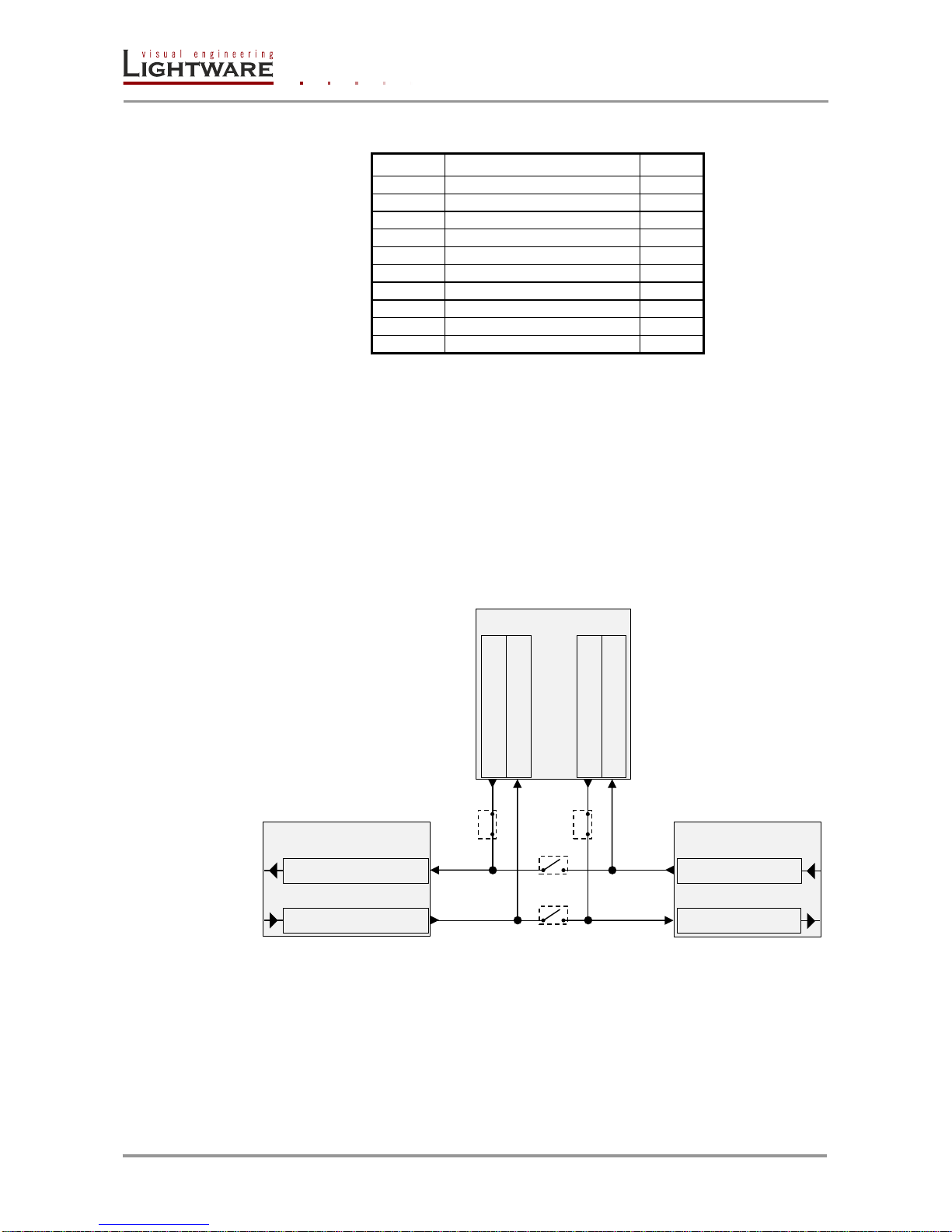
There are two kinds of operations for the unit regarding the serial port: you can control
the unit or use the bidirectional serial link through the DDC CAT cable with a compatible
HDMI-TP receiver.
1. In the first case the CPU in the transmitter can receive commands and send
responses either to and from the own serial port or to and from the serial port on the
receiver unit through the DDC line (2nd CAT cable).
Figure 3-1. UMX-TP-TX100R in CONTROL mode
TP connector
CPU
DSUB connector
CPU TP TX (OUT)
CPU DSUB TX (OUT)
CPU TP RX (IN)
CPU DSUB RX (IN)
Pin 2: DSUB TX OUT
Pin 6: TP RX IN
Pin 3: DSUB RX IN
Pin 3: TP TX OUT
Page 13
UMX-TP-TX100R
Programmer’s Reference Manual
Section 3. Operation modes Page 13 / 43
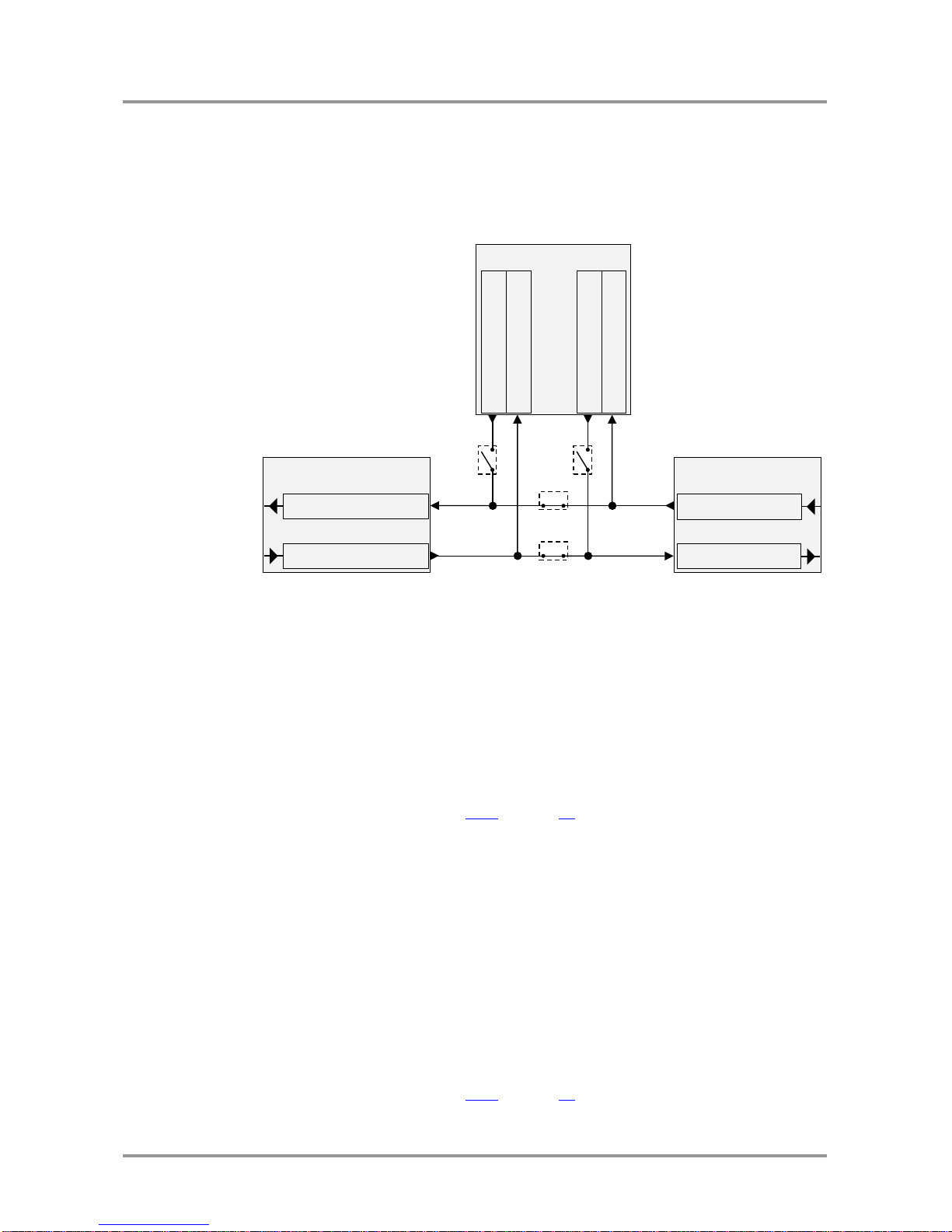
2. In case of the second mode the TX lines of the processor are in HiZ state and the
serial connectors on the transmitter and on the receiver are linked together through
the DDC CAT cable.
Figure 3-2. UMX-TP-TX100R in PASSTROUGH mode
Mentioning the facts above is important as there are two commands to set the operation:
{RS232=CONTROL}
Sets the mode when you can control the unit.
{RS232=PASS}
Sets the mode when the serial connector is used as a
serial link towards the receiver unit.
{RS232=?}
Queries the actual state, the response will be
(RS232=CONTROL) or (RS232=PASS).
For more information see section 4.4.5 on page 18.
Info: UMX-TP-TX100R stores the RS232 working mode and starts the saved one after reboot.
The default baud rate for control is 57600, the command to set the baud rate can be the
following:
{RS232BAUD=9600}
{RS232BAUD=19200}
{RS232BAUD=38400}
{RS232BAUD=57600}
{RS232BAUD=115200}
Of course in PASS mode the speed can be anything, but for changing and querying the
mode the previously set baud rate must be applied for the sent commands.
For more information see section 4.4.2 on page 17.
TP connector
CPU
DSUB connector
CPU TP TX (OUT)
CPU DSUB TX (OUT)
CPU TP RX (IN)
CPU DSUB RX (IN)
Pin 2: DSUB TX OUT
Pin 6: TP RX IN
Pin 3: DSUB RX IN
Pin 3: TP TX OUT
Page 14

Page 14 / 43 Section 4. Programmers reference
4. Programmers reference
Users can connect to the extender through serial port.
Lightware UMX-TP-TX100R can be controlled with external devices which can
communicate according to the extender protocol.
4.1. Serial port settings
UMX-TP-TX100R uses RS-232 communication port. D-SUB connector pin assignments
can be found in section 1.6 on page 10.
The device uses standard RS-232 interface with the following default settings:
57600 Baud, 8 data bit, 1 stop bit, no parity
The serial port baud rate can be changed with protocol command. See section 4.4.2 on
page 17.
4.2. Protocol description
The protocol description hereinafter stands for Lightware protocol.
The devices accept commands surrounded by curly brackets - { } - and responds with
data surrounded by round brackets - ( ) - only if a command was successfully executed.
All input commands are converted to uppercase, but respond commands can contain
upper and lower case letters as well.
Legend for control commands:
<in> = input number in 1 or 2 digit ASCII format (01,5,07,16 etc.)
<out> = output number in 1 or 2 digit ASCII format
<in²> = input number in 2 digit ASCII format (01, 02, 10, 12 etc.)
<out²> = output number in 2 digit ASCII format (01, 02, 10, 12 etc.)
<loc> = location number in 1, 2 or 3 digit ASCII format
<id> = id number in 1 or 2 digit ASCII format
<id²> = id number in 2 digit ASCII format
<italic> = italic parameters are optional
CrLf = Carriage return, Line feed (0x0D, 0x0A)
● = space character (0x20)
→ = each command issued by the controller
← = each response received from the router
Page 15

UMX-TP-TX100R
Programmer’s Reference Manual
Section 4. Programmers reference Page 15 / 43
4.3. Status and identification commands
4.3.1. View product type
Description: Identification of the device. Type ‘i’ or ‘I’ then the router responds its name.
Format
Example
Command
{I} → {i}
Response
(<PRODUCT_TYPE>)CrLf
←
(I:UMX-TP-TX100R)CrLf
Legend: <PRODUCT_TYPE> shows the router model.
Explanation: The connected device is an UMX-TP-TX100R.
4.3.2. View serial number
Description: The extender responds its 8-digit serial number.
Format
Example
Command
{S} → {s}
Response
(<SERIAL_NUMBER>)CrLf
←
(SN:10170142)CrLf
Legend: < SERIAL_NUMBER > shows the serial number of the extender.
Explanation: The connected device’s serial number is 10170142.
Info: Only the last 4 numbers are written onto the back of the router
4.3.3. View Firmware version of the CPU
Description: View the CPU firmware revision.
Format
Example
Command
{F} → {f}
Response
(FW:<FW_VER><S>)CrLf
←
(FW:1.0.9r)CrLf
Legend: <FW_VERSION> is the firmware version. It is followed by <s> string which may
indicate special versions. <s>=r indicates standard version.
Explanation: The connected device’s firmware version is 1.0.9r.
4.3.4. View installed controllers’ firmware
Description: Shows the firmware revisions of the installed controllers.
Format
Example
Command
{FC}
→
{fc}
Response
(CF●END)CrLf
←
(CF END)CrLf
Explanation: There is no installed controller. This command is reserved for compatibility
reasons.
4.3.5. View device’s temperature
Description: Queries temperature status.
Format
Example
Command
{ST}
→
{st}
Response
(ST●<DESC>)CrLf
←
(ST CPU N/A N/A N/A N/A N/A 36.2C)CrLf
Legend: <DESC> N/A N/A N/A N/A N/A – reserved for compatibility reasons
INNER TEMPERATURE
Explanation: Internal temperature is shown.
Page 16

Page 16 / 43 Section 4. Programmers reference
4.3.6. View CPU firmware compile time
Description: Shows the CPU firmware compile time.
Format
Example
Command
{CT}
→
{ct}
Response
(Compiled:<DATE>●<TIME>●
Build:<tag>)CrLf
←
(Compiled:Sep 21 2012 14:06:36
Build:4427)CrLf
Legend: <DATE> Month, Day and Year
<TIME> Hours, minutes and seconds
<tag> Identification number of the firmware
Explanation: The firmware was made in 21.09.2012, 14:06:36 and the identification
number of the firmware is 4427.
4.3.7. View installed I/O boards
Description: Shows the hardware name and revision of the installed cards. The number
of responses varies regarding the frame size (number of slots).
Format
Example
Command
{IS} → {is}
Response
(SL#●0●<MB_DESC>)CrLf
(SL●END)CrLf
←
←
(SL# 0 UMX-TP-TX100R SCH_1.2)CrLf
(SL END)CrLf
Legend: Slot 0 represents the motherboard.
<MB_DESC> The motherboard description contains the name and the
version number.
Explanation: The extender reports that it has one motherboard called UMX-TP-TX100R
and its version number is SCH_1.2.
4.4. System commands
4.4.1. Query current control protocol
Description: Shows the RS-232 control protocol.
Format
Example
Command
{P_?}
→
{p_?}
Response
(CURRENT●PROTOCOL●
=●#<x>)CrLf
← (CURRENT PROTOCOL = #1)CrLf
Legend: <x> stands for the active protocol.
Explanation: Protocol 1 is active here.
Info: User can query the protocol only. This command is reserved for compatibility reasons.
Page 17
UMX-TP-TX100R
Programmer’s Reference Manual
Section 4. Programmers reference Page 17 / 43
4.4.2. Change RS-232 baud rate
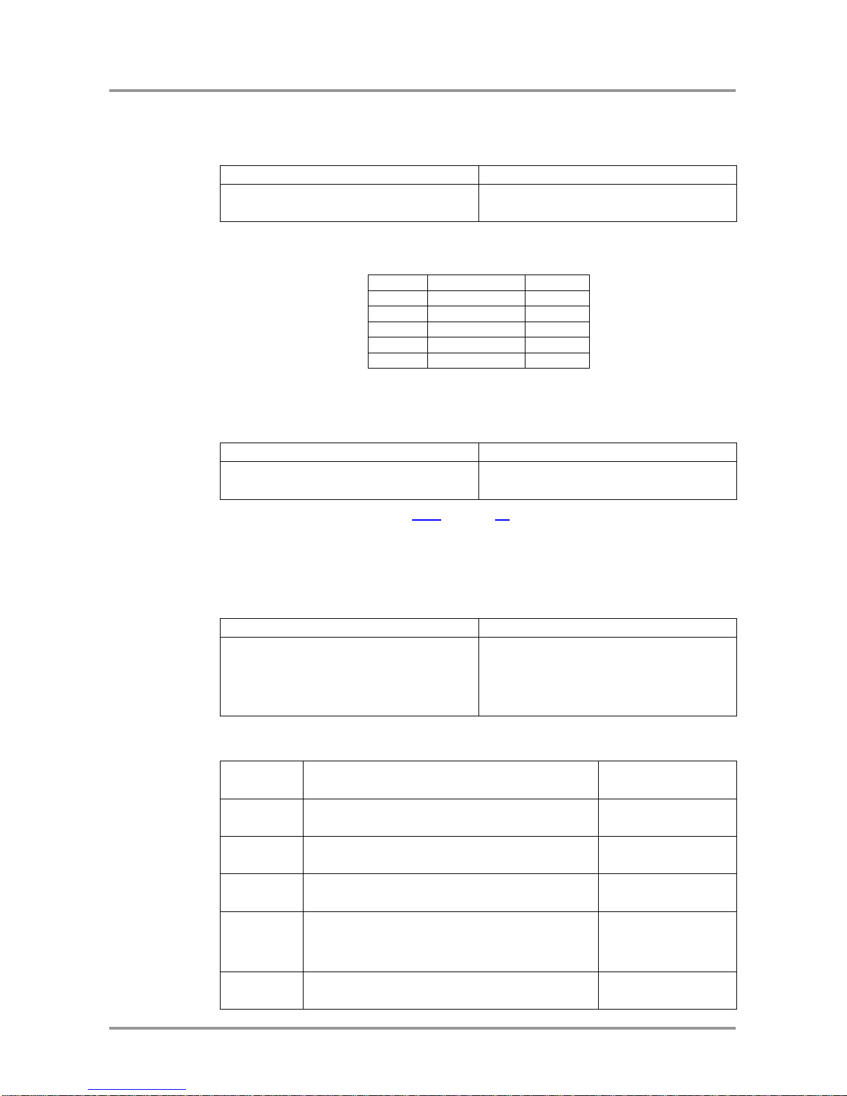
Description: The RS-232 baud rate can be set. The command has to be sent with the
earlier baud rate but the response comes with the new baud rate.
Format
Example
Command
{RS232BAUD=<rate>}
→
{RS232BAUD=9600}
Response
(RS232BAUD=<rate>)CrLf
←
(RS232BAUD=9600)CrLf
Explanation: The device RS-232 port is set to 9600 baud.
Possible settings:
<rate>
Baud rate
9600
9600 baud
19200
19 200 baud
38400
38 400 baud
57600
57 600 baud
(default)
115200
115 200 baud
4.4.3. Query RS-232 baud rate
Description: The RS-232 baud rate can be checked. It works via RS-232 as well, but if it
is used the command has to be sent with the appropriate baud rate.
Format
Example
Command
{RS232BAUD=?}
→
{RS232BAUD=?}
Response
(RS232BAUD=<rate>)CrLf
←
(RS232BAUD=57600)CrLf
Legend: Please read section 4.4.2 on page 17.
Explanation: The device communicates with 57600 baud on the RS-232 port.
4.4.4. Reload factory defaults
Description: Factory default settings can be reloaded for different functions separately.
Multiple functions can be entered.
Format
Example
Command
{FACTORY=<f1>;<f2>;…;<fx>}
→
{factory=xpoint;iocards;edidmem}
Response
(FACTORY●<f1>…)CrLf
(FACTORY●<f2>…)CrLf
…
(FACTORY●<fx>…)CrLf
←
←
←
(FACTORY XPOINT…)CrLf
(FACTORY IOCARDS…)CrLf
(FACTORY EDIDS…)CrLf
Legend: <f1>, <f2> are the names of the functions which have to be reset to factory
default. Any number of <fx> can be entered, separated by semicolons.
<fx>
Restores factory settings to
Additional response
XPOINT
Crosspoint table and configuration
none
IONAMES
Input and output names
(INAME#1=Input1)
(ONAME#1=Output1)
IOCARDS
All I/O settings for boards currently in the frame
none
EDIDMEM
Clear User and Dynamic EDIDs
(DE_OK)
(E_SW_OK)
…
(E_SW_OK)
ALL
Restores all of the factory settings listed above
none
Page 18
Page 18 / 43 Section 4. Programmers reference
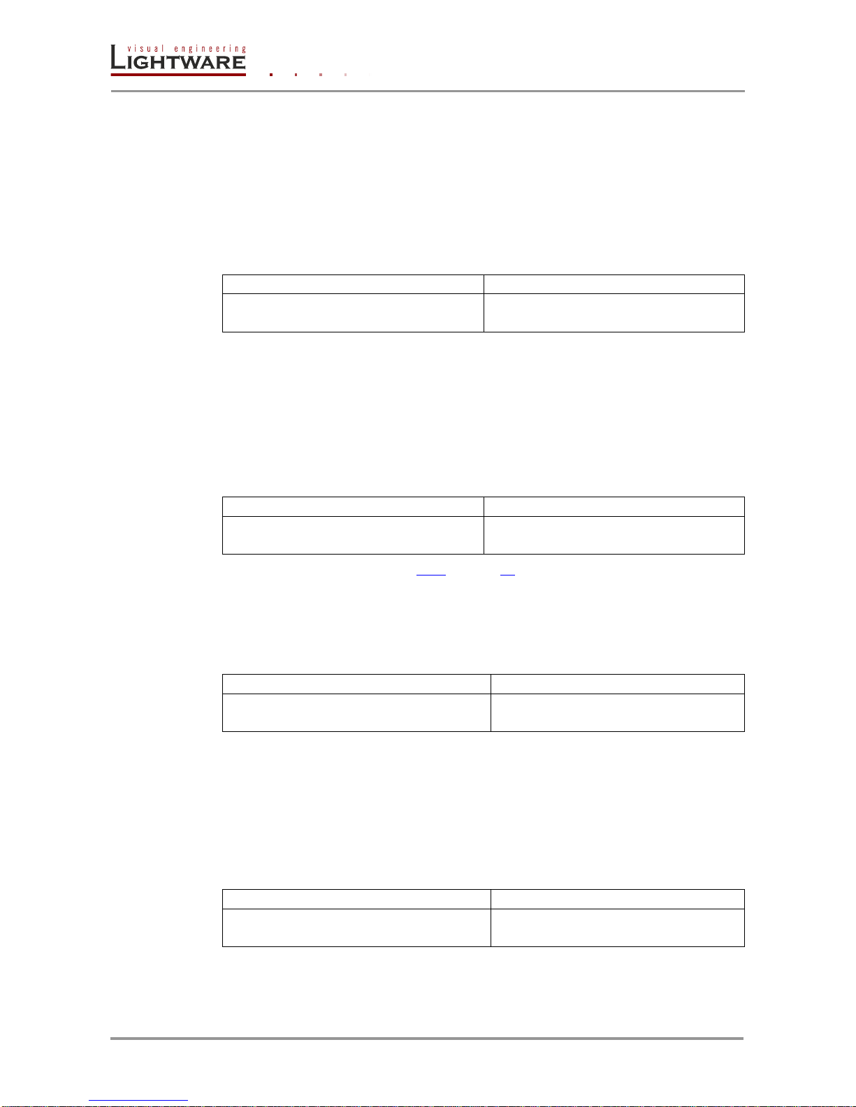
Explanation: Factory default settings reloaded for crosspoint and I/O card configurations
and emulated EDIDs.
Info: The response may contain additional messages as the router makes the configurations.
These responses can be omitted.
Info: After resetting the needed parameters, the device restarts.
4.4.5. Set the RS232 operation mode
Description: This command sets the RS232 port operation mode.
Format
Example
Command
{RS232=<mode>}
→
{rs232=control}
Response
(RS232=<mode>)CrLf
←
(RS232=CONTROL)CrLf
Legend: <mode> Two kinds of operation modes can be:
<CONTROL> The CPU in the transmitter can receive
commands and send responses.
<PASS> The serial connectors on the transmitter
and on the receiver are linked together.
Explanation: The device can be controlled via RS232 port.
4.4.6. Query the RS232 operation mode
Description: This command queries the current RS232 operation mode.
Format
Example
Command
{RS232=?}
→
{rs232=?}
Response
(RS232=<mode>)CrLf
←
(RS232=CONTROL)CrLf
Legend: Please read section 4.4.5 on page 18.
Explanation: The device can be controlled via RS232 port.
4.4.7. Count HDCP keys
Description: If there is an HDCP source on the HDMI input of the device, the device can
ask the source whether it can handle <num> piece of sink devices.
Format
Example
Command
{:HDCPTEST<in>@<num>}
→
{:hdcptest1@8}
Response
(HDCPTEST=SUCCESS)CrLf
←
(HDCPTEST=SUCCESS)CrLf
Legend: <in> input port where the key counting will be executed. This input
port must be selected.
<num> the number of the HDCP keys
Explanation: The source on the 1st input can handle 8 HDCP sink devices.
4.4.8. Clear HDCP key cache
Description: The device stores the HDCP keys from the connected devices. These
cached keys can be cleared with this command.
Format
Example
Command
{:HDCPRESET}
→
{:hdcpreset}
Response
(Done)CrLf
←
(Done)CrLf
Explanation: HDCP key cache is cleared.
Info: This function is useful when too many keys were cached and a connected source device
cannot accept so many keys.
Page 19

UMX-TP-TX100R
Programmer’s Reference Manual
Section 4. Programmers reference Page 19 / 43
4.4.9. Restart matrix router
Description: The extender can be restarted without unplugging power.
Format
Example
Command
{RST}
→
{rst}
Response
(Booting…)CrLf
(<name>●Ready!)CrLf
← ← (Booting…)CrLf
(UMX-TP-TX100R Ready!)
Legend: <name> is the type of the extender
Explanation: The extender reboots and sends a message when it is ready.
Info: The response can be seen only if the connection to the extender is still alive.
4.4.10. View error list
Description: Shows the basic error list since last boot up.
Format
Example
Command
{ELIST=?}
→
{elist=?}
Response
(ELIST#<num>●<elevel>●<code>
●<param>●<occ>)CrLf
…
(ELIST#<num>●<elevel>●<code>
●<param>●<occ>)CrLf
←
←
(ELIST#1 Notice BOOT
p:6 o:1)CrLf
…
(ELIST#2 Notice READY
p:0 o:1)CrLf
Legend: <num>: line number
<elevel>: NOTICE = Not an error. Initialization information.
WARNING = Possible problem without influencing normal
operation.
MATTER = Problem that may lead to further errors.
ERROR = Serious error. Must report to support.
FATAL = Fatal error. Normal operation is not possible.
<code>: short name for type of log entry
<param>: technical parameter
<occ>: occurrence number for this type of log entry
Explanation: There are no errors only standard notices that occur on boot up.
Info: The error list can contain NOTICEs and WARNINGs under normal operation. These
entries do not mean that there is any problem with the matrix!
Page 20

Page 20 / 43 Section 4. Programmers reference
4.4.11. Configure remote alerts
Description: The device logs different levels of errors. Configure which level of errors
has to be sent out as an alarm message.
Format
Example
Command
{ELEVELSEND#<p>=
<0>,<1>,<2>,<3>,<4>}
→
{ELEVELSEND#1=0,0,1,1,1}
Response
(ELEVELSEND#<p>=
<0>,<1>,<2>,<3>,<4>)CrLf
←
(ELEVELSEND#1=0,0,1,1,1)CrLf
Explanation: The device will send an immediate message on all control interfaces when
a ‘matter’, ‘error’ or ‘fatal’ level error occurs.
Legend: <p>: Adjusted control interface must be 1 = RS-232
<0>: ‘Notice’ level events 0 = no immediate message send
1 = immediate message
<1>: ‘Warning’ level events 0 = no immediate message send
1 = immediate message
<2>: ‘Matter’ level events 0 = no immediate message send
1 = immediate message
<3>: ‘Error’ level events 0 = no immediate message send
1 = immediate message
<4>: ‘Fatal’ level events 0 = no immediate message send
1 = immediate message
See section 4.4.10 on page 19 for more information about error levels.
4.4.12. Query level of remote alerts
Description: User can check which level of errors has to be sent out as an alarm
message.
Format
Example
Command
{ELEVELSEND#<p>=?}
→
{ELEVELSEND#1=?}
Response
(ELEVELSEND#<p>=
<0>,<1>,<2>,<3>,<4>)CrLf
←
(ELEVELSEND#1=0,0,1,1,1)CrLf
Legend: Please read section 4.4.11 on page 20.
Explanation: The device will send an immediate message on all control interfaces when
a ‘matter’, ‘error’ or ‘fatal’ level error occurs.
4.4.13. Set the priority settings
Description: This command sets the video priority mode.
Format
Example
Command
{VIDEOPRIORITY=<pmode>}
→
{videopriority=1}
Response
(VIDEOPRIORITY=<pmode>)CrLf
←
(VIDEOPRIORITY=1)CrLf
Legend: <pmode> Two kinds of video priority modes can be:
<0> First detect
First the device check the HDMI than the VGA
video input port. That port will be selected which
contains valid video signal.
<1> HDMI priority
If there is a valid signal on the HDMI input, these
port always will be selected, even if the active port
was the VGA input port.
Explanation: The device uses HDMI priority in video autoselect mode.
Page 21

UMX-TP-TX100R
Programmer’s Reference Manual
Section 4. Programmers reference Page 21 / 43
4.4.14. Query the priority settings
Description: This command queries the video priority mode.
Format
Example
Command
{VIDEOPRIORITY=?}
→
{videopriority=?}
Response
(VIDEOPRIORITY=<pmode>)CrLf
←
(VIDEOPRIORITY=1)CrLf
Legend: Please read section 4.4.13 on page 20.
Explanation: The device uses HDMI priority in the autoselect mode.
4.5. EDID router commands
The EDID router manipulates the EDID memory, which has memory locations that are
assigned to specific input or output ports. Please read section 2 on page 11 about EDID
memory structure.
Warning! Emulated EDIDs can be switched with the rotary switches only.
4.5.1. Save EDID to user memory (Learn EDID)
Description: Learn EDID from <loc2> to <loc1>.
Format
Example
Command
{<loc1>:<loc2>}
→
{u3:d1}
Response
(E_SW_OK)CrLf
(E_S_C) CrLf
← ← (E_SW_OK)CrLf
(E_S_C)CrLf
Legend: <loc1> has to be ‘Uxx’.
<loc2> can be ‘Fxx’ or ‘Uxx’ or ‘Dxx’.
Explanation: EDID from the output 1 is saved to user EDID #3.
Info: The router sends (E_S_C) only if the new EDID is different from the earlier one.
4.5.2. View emulated EDIDs on all inputs
Description: Shows the currently emulated EDIDs for both input. The value at the given
index (<in1>, <in2>) shows which EDID is used on that particular input.
Format
Example
Command
{VEDID}
→
{vedid}
Response
(VEDID●<in1>●<in2>)CrLf
←
(VEDID F001 D001)CrLf
Legend: Both <inx> indexes show a <loc> which was copied to that input port.
Explanation: F001 (Factory preset EDID F01) is emulated on the input 1. EDID from
output is dynamically emulated on input 2.
Page 22
Page 22 / 43 Section 4. Programmers reference
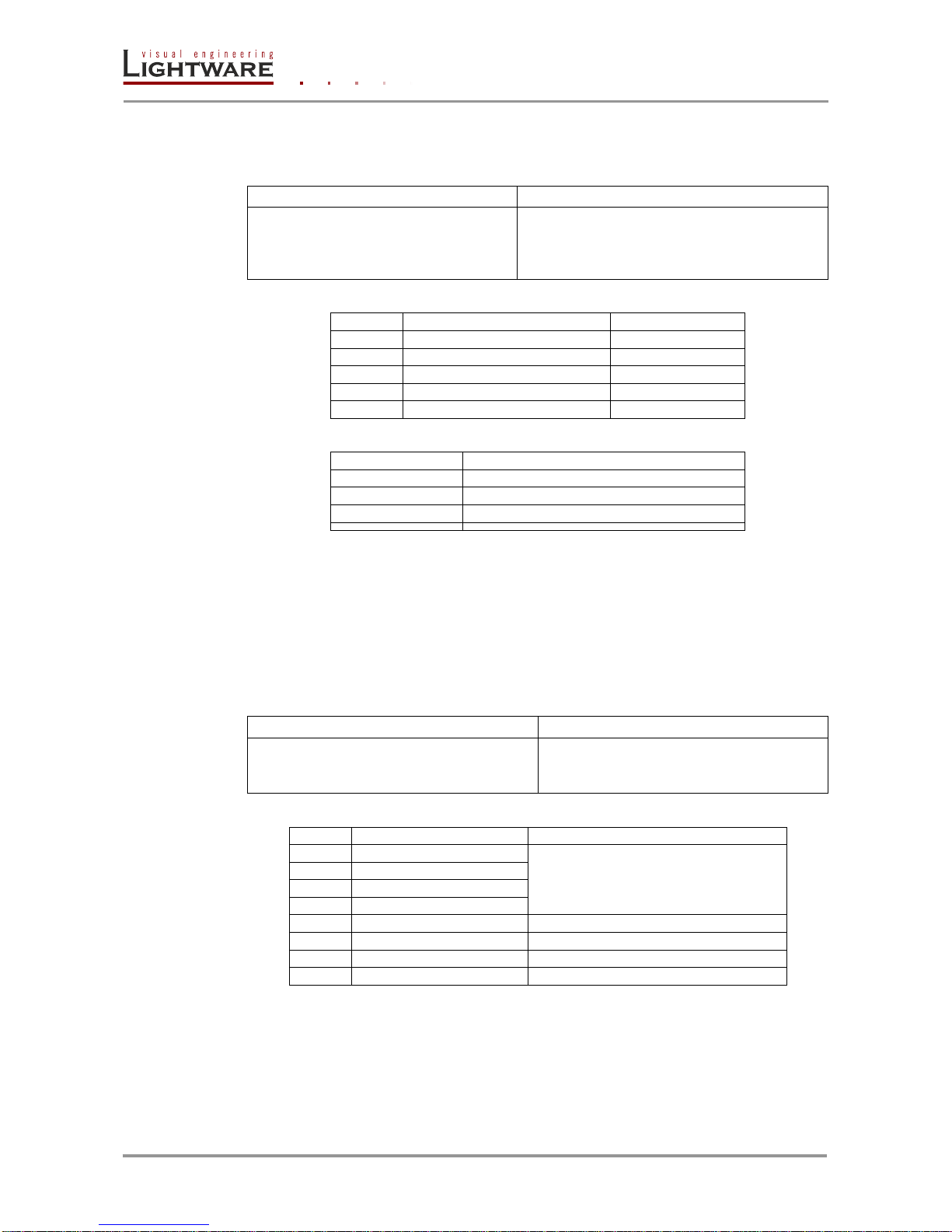
4.5.3. Watch EDID validity table
Description: Shows EDID validity table, which contains information about the EDID
memory states.
Format
Example
Command
{WV<type>}
→
{wv*}
Response
(EV<type>●
<VALIDITY_TABLE>)CrLf
←
←
←
(EVU 31111111)CrLf
(EVD 1)CrLf
(EVE 11)CrLf
Legend:
<type>
<name>
Response length
F
Factory preset EDIDs
10
U
User saved EDIDs
8
D
Dynamic EDID
1
E
Emulated EDIDs
2
*
All ‘U’, ‘D’ and ‘E’ EDIDs
Each number represents the EDID validity state for the corresponding memory location.
Value
Description
‘0’
invalid EDID
‘1’
valid EDID
‘3’
changed EDID
Explanation: There is one ‘3’ in the first row on the 1st position. This means that the user
EDID is changed since the last EDID query on that port.
Info: If a changed EDID is queried by the {WH} command (see the next section), its value
returns to ‘1’.
Info: EDID deleting means the universal EDID will be upload to the deleted EDID’s place.
4.5.4. View EDID header
Description: Shows basic information about EDIDs in the memory.
Format
Example
Command
{WH<loc>}
→
{whe1}
Response
(EH#<loc>●
<EDID_HEADER>)CrLf
← (EH#E1 LWR 1920x1080@60Hz
Univ_HDMI_DC)CrLf
Legend: Depending on <loc> the query can be for one EDID, all EDID in the block.
<loc>
Result
Response
Fxx
Factory EDID query
header for one EDID
Uxx
User EDID query
Dxx
Dynamic EDID query
Exx
Emulated EDID query
F*
All Factory preset EDIDs
headers for all (10) Factory EDIDs
U*
All User saved EDIDs
headers for all (8) user EDIDs
D*
All Dynamic EDIDs
header from the output (1)
E*
All Emulated EDIDs
headers from both inputs (2)
<EDID_HEADER> consists of 3 fields separated by spaces:
PNPID code The three letter abbreviation of the manufacturer
Preferred resolution The resolution and refresh rate stored in the preferred detailed
timing block.
Name The name of display device stored in product descriptor.
Explanation: Shows the EDID from the input 1.
Page 23

UMX-TP-TX100R
Programmer’s Reference Manual
Section 4. Programmers reference Page 23 / 43
4.5.5. Download EDID content from the router
Description: EDID hex bytes can be read directly. The router will issue the whole content
of the EDID present on memory location <loc> (256 bytes).
Format
Example
Command
{WE<loc>}
→
{wef1}
Response
(EB#<loc>●<B1>
●<B2>●..●<B256>)CrLf
←
(EB#F1 00 FF FF FF FF FF FF 00 32 F2
00 00 00 .. .. .. 00 92) CrLf
Legend: <B1>..<B256> are space separated hex characters represented in ASCII
format.
Explanation: Full EDID from memory location 1 is downloaded.
4.5.6. Upload EDID content to the router
Description: EDID hex bytes can be written directly to the user programmable memory
locations.
Sequence:
Step 1. Prepare the router to accept EDID bytes to the specified location <loc> with
command {WL#<loc>}
Step 2. Router responds that it is ready to accept EDID bytes with (E_L_S)CrLf
Step 3. Send 1 block of EDID (1 block consist of 8 bytes of hex data represented in ASCII
format) with command:
{WB#<num>●<B1>●<B2>●<B3>●<B4>●<B5>●<B6>●<B7>●<B8>}
Step 4. The router acknowledges with response (EL#<num>)
Step 5. Repeat steps 3 and 4 to send the remaining 31 blocks of EDID (32 altogether)
Step 6. After the last acknowledge, the router indicates that the EDID status changed by
sending (E_S_C) CrLf
Format
Example
Command
{WL#<loc>}
→
{wl#u3}
Response
(E_L_S)CrLf
←
(E_L_S) CrLf
Command
{WB#1●<B1>●<B2>●<B3>
●<B4>●<B5>●<B6>●<B7> ●<B8>}
→
{wb#1 00 FF FF FF FF FF FF 00}
Response
(EL#<num>)CrLf
←
(EL#1)CrLf
Command
{WB#2●<B9>●<B10>
●<B11>●<B12>●<B13>
●<B14>●<B15>●<B16>}
→
{wb#2 38 A3 8E 66 01 01 01 01}
Response
(EL#<num>) CrLf
←
(EL#2)CrLf
… …
Command
{WB#32●<B249>●<B250>
●<B251>●<B252>●<B253>
●<B254>●<B255>●<B256>}
→
{wb#32 36 59 42 0A 20 20 00 96}
Response
(EL#<num>) CrLf
←
(EL#32)CrLf
Response
(E_S_C) CrLf
←
(E_S_C)CrLf
Legend: <num> represents the sequential number of every 8 byte part of EDID. <num>
is between 1 and 32. <B1>..<B256> are the bytes of EDID.
Explanation: Full EDID uploaded to memory location U3.
Page 24
Page 24 / 43 Section 4. Programmers reference
4.5.7. Delete EDID from memory
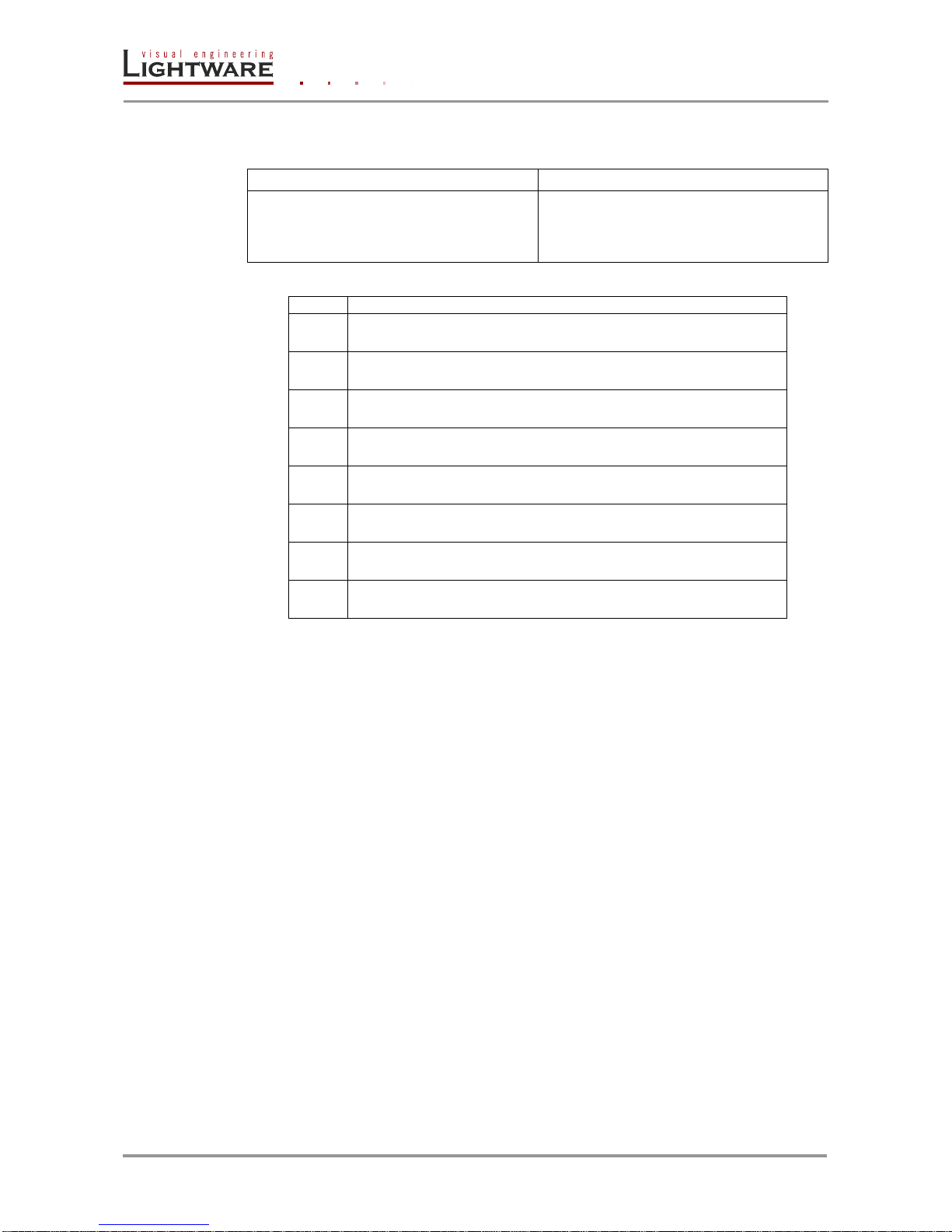
Description: Clear EDID from memory location <loc>.
Format
Example
Command
{DE<loc>}
→
{deu3}
Response
(E_SW_OK)CrLf
(DE_OK)CrLf
(E_S_C)CrLf
←
←
←
(E_SW_OK)
(DE_OK)CrLf
(E_S_C)CrLf
Legend: Depending on <loc>, one EDID, or all EDIDs in a block can be cleared.
<loc>
Result
Fxx
Not valid! Factory EDID cannot be deleted. No response.
Uxx
Specified User EDID is deleted.
Dxx
Specified Dynamic EDID is deleted. It will be empty until a new
monitor is connected.
Exx
Specified Emulated EDID cleared. By default F49 EDID is copied
to it.
F*
Not valid! Factory EDID cannot be deleted. No response.
U*
All User EDIDs are deleted.
D*
All Dynamic EDIDs are deleted. They will be empty until a new
monitor is connected.
E*
All Emulated EDIDs are cleared. By default F49 EDID is copied
to them.
Explanation: Third user EDID is cleared from memory.
4.6. Control commands
Description: The following commands with <A/V/AV> option can take effect in multiple
layers, according to their parameters. Depending on ‘A’ or ‘V’ it can change only the
Audio, or only the Video layer; or ‘AV’ changes both.
Info: <A/V/AV> option usually can be skipped for legacy purposes.
In this case using router commands the router changes all (Video & Audio) layers, but
using status commands it displays information about only the Video layer.
Please use AV option, when available.
Page 25
UMX-TP-TX100R
Programmer’s Reference Manual
Section 4. Programmers reference Page 25 / 43
4.6.1. Switch one input to one output
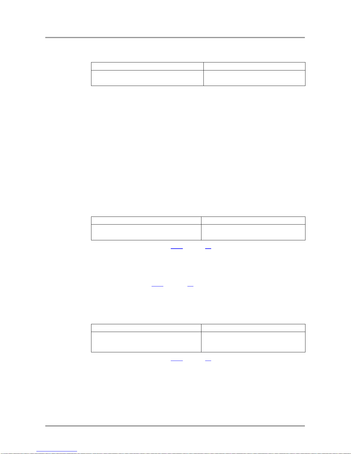
Description: This command switches the output to an input.
Format
Example
Command
{<in>@<out>●<A/V/AV>}
→
{2@1 av}
Response
(O<out²>●I<in²>●<A/V/AV>)CrLf
←
(O01 I02 AV)CrLf
Legend: <A/V/AV>: Layer select:
A: Audio layer
V: Video layer
AV: Audio&Video layer
<in> must be 1,2 or 3.
1: HDMI input
2:VGA input
3: automatic source selection
Explanation: The example shows how to connect both Audio and Video from input 2 to
output 1.
Info: If the command is used without the <A/V/AV> parameter, both layers are switched.
Info: UMX-TP-TX100R does not support disconnecting command. {0@<out>}
4.6.2. View video connection on the output
Description: This command shows the video connection status of the output.
Format
Example
Command
{?<out>}
→
{?1}
Response
(O<out²>●I<in²>)CrLf
←
(O01●I01)CrLf
Legend: Please read section 4.6.1 on page 25.
<out> must be 1, 01 or 001.
Explanation: The example shows that video output is connected to input 1
Info: This command kept for legacy purposes; to get information about all layers, please use
the multilayer command: 4.6.3 on page 25.
Info: The response shows connections only for the video layer.
4.6.3. View all connections on the output
Description: This command displays the connections on a single or multiple layers.
Format
Example
Command
{VC●<A/V/AV>}
→
{vc●av}
Response
(ALLV●<in²>)CrLf
(ALLA●<in²>)CrLf
←
(ALLV●01)CrLf
(ALLA●01)CrLf
Legend: Please read section 4.6.1 on page 25.
Explanation: The response contains all the connections, if both layers are selected the
response is two messages.
The example shows that output 1 Audio & Video are connected to input 1
Audio & Video.
Info: If the command is used without the <A/V/AV> parameter, the response shows only the
video layer connections.
Page 26

Page 26 / 43 Section 4. Programmers reference
Renaming Inputs / Output
Description: Allows storing names for each input / output. Any 16-byte long string is
allowed (16 characters). All characters are converted to uppercase!
4.6.4. Rename an input
Format
Example
Command
{INAME#<id>=<input_name>}
→
{iname#2=Media Player}
Response
(INAME#<id>=<input_name>)CrLf
←
(INAME#2=MEDIA PLAYER)CrLf
Legend: <id> must be 1 or 2.
Explanation: Input 2 was named as “MEDIA PLAYER”.
4.6.5. Rename the output
Format
Example
Command
{ONAME#<id>=<output_name>}
→
{ONAME#1=Monitor }
Response
(ONAME#<id>=<output_name>)CrLf
←
(ONAME#1=MONITOR)CrLf
Legend: <id> must be 1.
Explanation: Output was named as “MONITOR”.
Query names of Inputs / Output
Description: Each input / output name can be read from the router.
4.6.6. Read an input’s name
Format
Example
Command
{INAME#<in>=?}
→
{iname#2=?}
Response
(INAME#<in>= <input_name>)CrLf
←
(INAME#2=MEDIA PLAYER)CrLf
Legend: <id> must be 1 or 2.
Explanation: Name for input 2 is “MEDIA PLAYER”.
4.6.7. Read the output’s name
Format
Example
Command
{ONAME#<out>=?}
→
{oname#1=?}
Response
(ONAME#<out>=<output_name>)CrLf
←
(ONAME#1=MONITOR)CrLf
Legend: <id> must be 1.
Explanation: Name for the output is “MONITOR”.
Set default names of Inputs / Output
Description: Renames all input / output names to the default: Input 1, Input 2 / Output 1
respectively.
4.6.8. Reload default input names
Format
Example
Command
{INAME#<id>=!}
→
{iname#1=!}
Response
(INAME#<id>=Input●<id>)CrLf
←
(INAME#1=Input 1)CrLf
Legend: <id> must be 1 or 2.
Explanation: The first input name is set to default: “Input 1”.
Page 27

UMX-TP-TX100R
Programmer’s Reference Manual
Section 4. Programmers reference Page 27 / 43
4.6.9. Reload default output name
Format
Example
Command
{ONAME#<id>=!}
→
{oname#1=!}
Response
(ONAME#<id>=Output●<id>)CrLf
←
(ONAME#1=Output 1)CrLf
Legend: <id> must be 1.
Explanation: The output name is set to default: “Output 1”.
4.7. Port status commands
4.7.1. Input port status
Description: Shows the actual status of the input ports.
Format
Example
Command
{:ISD}
→
{:isd}
Response
(ISD●<INPUT_D>)CrLf
←
(ISD 00)CrLf
Explanation: This command is reserved for compatibility reasons.
Legend: <INPUT_D> contains 2 decimal numbers. Each number must be 00.
4.7.2. Output port status
Description: Shows the actual status of the output ports.
Format
Example
Command
{:OSD}
→
{:osd}
Response
(OSD●<OUTPUT_D>)CrLf
←
(OSD 00)CrLf
Explanation: This command is reserved for compatibility reasons.
Legend: <OUTPUT_D> contains 1 decimal numbers. It must be 0.
4.7.3. All port status
Description: Shows the actual status of all input and output ports.
Format
Example
Command
{PS}
→
{ps}
Response
(PS●<INPUT_D>,<OUTPUT_D>)CrLf
←
(PS 00, 0)CrLf
Explanation: This command is reserved for compatibility reasons.
Legend: <INPUT_D> and <OUTPUT_D> is the same as for {:ISD} and {:OSD}
commands. The input and output state tables are separated with a comma “,”
Page 28

Page 28 / 43 Section 4. Programmers reference
4.8. Input properties
The following commands are setting up the properties of the input ports. If only one or a
few parameters have to be modified, the protocol enables to mask the other parameters,
so they can stay untouched. To mask a parameter use “x” or “X” as its value.
Example: {:ANALOG#2@SI=x;x;x;x;210;x;} Only change the horizontal position on the
input port 2.
4.8.1. Set input port properties
Description: This command changes the setup of the input ports.
Format
Example
Command
{:DVII#<in>@<S/A>I=<VIDEO>;<X1>;<X2>;
<HDCP>}
→
{:dvii#1@si=x;x;x;1}
Response
(DVII#<in>@<S/A>I=<VIDEO>;<X>;<X>;
<HDCP>;<STATUS>;<SOURCE>;
<ATIM1/DCS>;<ATIM2/DRES>;
<ARES/HAUDIO>;<HASAMP><HCH>)CrLf
←
(DVII#1@SI=D;x;x;
1;3;H;
20;1920x1080p60;
P;48;)CrLf
Explanation: This command enables the HDCP encryption.
Legend: <S/A>: Affected ports:
S = single selected input
A = all inputs
<VIDEO> Video source: (read-only)
A = Automatic analog (color space detected by sync)
D = Digital (HDMI / YPbPr)
Info: Video source gives information about the source. It is a read-only parameter. Automatic
analog (A) setting available with analog VGA INPUT and Digital (D) setting available with
HDMI INPUT.
<X1>: Reserved for compatibility reasons. Don’t care.
<X1>: Reserved for compatibility reasons. Don’t care.
Info: The following parameters are available above 1.0.9 firmware version
Info: HDCP setting available only on the HDMI input port.
<HDCP>: HDCP capability:
0 = disabled,
1 = enabled.
Info: The following parameters cannot be set, they only appear in response.
<STATUS> Status (hexadecimal):
bit 0: (LSB): Power 5V
0 = not detected
1 = detected
bit 1: Source signal HDCP:
0 = not protected
1 = protected
bit 2: Don’t care
bit 3: Don’t care
<SOURCE> Actual video source:
H = HDMI
D = DVI
R = RGBHV (analog signal, separate HV sync)
C = Component signal (analog signal, embedded sync)
- = No video detected.
Page 29

UMX-TP-TX100R
Programmer’s Reference Manual
Section 4. Programmers reference Page 29 / 43
Source dependent parameters:
Analog signal properties are displayed, when <SOURCE> = R / C:
<ATIM1> Analog timing1:
0 = SMTPE standard
1 = User saved preset
2 = EDID detailed timing
3 = Factory preset
4 = GTF formula
5 = User modified (not saved)
<ATIM2> Analog timing2: (depending on <ATIM1>)
<ATIM1> = 0 -> SMTPE record number
<ATIM1> = 1 -> User preset number
<ATIM1> = 2 -> Detailed timing number
<ATIM1> = 3 -> Factory preset number
<ATIM1> = 4 -> Fixed zero.
<ARES> Resolution string. (example: 1600x1200p60)
Digital signal properties are displayed, when <SOURCE> = H / D:
<DCS> 2 byte hexadecimal number:
bit 0 = 1: Color depth: 30 bit/pixel (not supported)
bit 1 = 1: Color depth: 36 bit/pixel
bit 2 = 1: Color depth: 48 bit/pixel (not supported)
bit 0&1&2 =0: Color depth: 24 bit/pixel
bit 4: Color space: YCbCr422
bit 5: Color space: YCbCr444
<DRES> Incoming resolution string. (example: 1600x1200p60)
If HDMI signal present <SOURCE> = H, there are more HDMI specific parameters:
<HAUDIO> HDMI Audio properties:
0 = no audio
P = 2 channel stereo (L-PCM)
M = Multichannel-PCM (M-PCM)
S = Compressed audio
H = HBR audio
D = DST audio (not supported)
E = DSD audio (not supported)
<HASAMP> If <HAUDIO> not S or H: HDMI audio sample rate in kHz.
<HAUDIO> = S (Compressed) multiply by 32,
<HAUDIO> = H (HBR) multiply by 4
32
32
kHz
44
44,1
kHz
48
48
kHz
88
88,2
kHz
96
96
kHz
176
176,4
kHz
192
192
kHz
<HCH> Contains CEA-861 compatible channel assignment,
if M-PCM signal present:
0x00 - - - - - -
FR
FL
0x01 - - - - - LFE
FR
FL
0x02 - - - -
FC - FR
FL
0x03 - - - -
FC
LFE
FR
FL
0x04 - - - RC - -
FR
FL
0x05 - - - RC - LFE
FR
FL
0x06 - - - RC
FC - FR
FL
0x07 - - - RC
FC
LFE
FR
FL
0x08 - -
RR
RL - -
FR
FL
0x09 - -
RR
RL - LFE
FR
FL
0x0A - -
RR
RL
FC - FR
FL
Page 30

Page 30 / 43 Section 4. Programmers reference
0x0B - -
RR
RL
FC
LFE
FR
FL
0x0C
-
RC
RR
RL - -
FR
FL
0x0D
-
RC
RR
RL - LFE
FR
FL
0x0E
-
RC
RR
RL
FC - FR
FL
0x0F
-
RC
RR
RL
FC
LFE
FR
FL
0x10
RRC
RLC
RR
RL - -
FR
FL
0x11
RRC
RLC
RR
RL - LFE
FR
FL
0x12
RRC
RLC
RR
RL
FC - FR
FL
0x13
RRC
RLC
RR
RL
FC
LFE
FR
FL
0x14
FRC
FLC - - - -
FR
FL
0x15
FRC
FLC - - - LFE
FR
FL
0x16
FRC
FLC - -
FC - FR
FL
0x17
FRC
FLC - -
FC
LFE
FR
FL
0x18
FRC
FLC
-
RC - -
FR
FL
0x19
FRC
FLC
-
RC - LFE
FR
FL
0x1A
FRC
FLC
-
RC
FC - FR
FL
0x1B
FRC
FLC
-
RC
FC
LFE
FR
FL
0x1C
FRC
FLC
RR
RL - -
FR
FL
0x1D
FRC
FLC
RR
RL - LFE
FR
FL
0x1E
FRC
FLC
RR
RL
FC - FR
FL
0x1F
FRC
FLC
RR
RL
FC
LFE
FR
FL
Where:
FL
Front Left
FC
Front Center
FR
Front Right
FLC
Front Left Center
FRC
Front Right Center
RL
Rear Left
RC
Rear Center
RR
Rear Right
RLC
Rear Left Center
RRC
Rear Right Center
LFE
Subwoofer
4.8.2. Query input port properties
Description: Check status of the input ports.
Format
Example
Command
{:DVII#<in>@<S/A>I=?}
→
{:dvii#1@si=?}
Response
(DVII#<in>@<S/A>I=
<VIDEO>;
<X1>;
<X2>;
<HDCP>;
<STATUS>;
<SOURCE>;
<ATIM1/DCS>;
<ATIM2/DRES>;
<ARES/HAUDIO>;
<HASAMP>;
<HCH>;)CrLf
←
(DVII#1@SI=
D;
x;
x;
1;
3;
H;
20;
1920x1080p60;
P;
48;)CrLf
Legend: Please read section 4.8.1 on page 28.
Explanation: This command queries the HDMI input port properties.
Page 31

UMX-TP-TX100R
Programmer’s Reference Manual
Section 4. Programmers reference Page 31 / 43
4.8.3. Set analog timing properties
Description: This command changes the setup of the analog timing data.
Format
Example
Command
{:ANALOG#<in>@<S/A>I=
<PHS>;<FHS>;
<HS>;<VS>;
<HP>;<VP>;}
→
{:analog#2@si=
10;2160;
1600;1200;
455;41;}
Response
(DVII#<in>@<S/A>I=
<PHS><FHS>;
<HS>;<VS>;
<HP>;<VP>;
<LCF>;
<FORM>;<VSP>;<HSP>;
<FPS>;)CrLf
←
(ANALOG#2@SI=
10;2160;
1600;1200;
455;41;
1124;
P;-;-;
50;)CrLf
Legend: <S/A>: Affected ports:
S = single selected input
A = all inputs
<PHS> Phase
<FHS> Full Horizontal Size
<HS> Horizontal Size
<VS> Vertical Size
<HP> Horizontal Position
<VP> Vertical Position
Info: The following parameters cannot be set, they only appear in response.
<LCF> Full Vertical Size (Line Count per Field)
<FORM> Format: Progressive or Interlaced
<VSP> Vertical Sync. Polarity
<HSP> Horizontal Sync. Polarity
<FPS> Frame Per Sec in Hz
4.8.4. Query analog timing properties
Description: Check analog timing data of the input ports.
Format
Example
Command
{:ANALOG#<in>@<S/A>I=?}
→
{:analog#2@si=?}
Response
(ANALOG#<in>@<S/A>I=
<PHS>;<FHS>;
<HS>;<VS>;
<HP>;<VP>;<LCF>;
<FORM>;<VSP>;<HSP>;<FPS>)CrLf
←
(ANALOG#2@SI=
0;2160;
1600;1200;
455;41;1242;
P;+;+;60;)CrLf
Legend: Please read section 4.8.3 on page 31.
4.8.5. Reset analog timing properties
Description: This command resets the analog timing properties.
Format
Example
Command
{:ANALOG#<in>@<S/A>I=RESET}
→
{:analog#2@si=reset}
Response
(ANALOG#<in>@<S/A>I=
<PHS>;<FHS>;
<HS>;<VS>;
<HP>;<VP>;<LCF>;
<FORM>;<VSP>;<HSP>;<FPS>)CrLf
←
(ANALOG#1@SI=
0;2160;
1600;1200;
455;41;1242;
P;+;+;60;)CrLf
Legend: Please read section 4.8.3 on page 31.
Page 32
Page 32 / 43 Section 4. Programmers reference
4.8.6. Set analog color properties
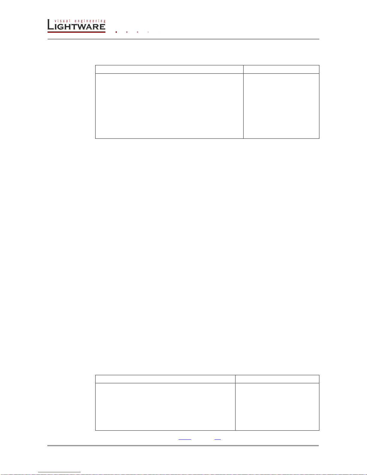
Description: Set analog color properties data of the input ports.
Format
Example
Command
{:PICTURE#<in>@<S/A>I=
<DF_CHA>;<DF_CHB>;<DF_CHC>;
<G_CHA>;<G_CHB>;<G_CHC>;
<O_CHA>;<O_CHB>;<O_CHC>;
<CONT>;<SAT>;<BRIGHT>;<HUE>;)
→
{:picture#2@si=
1023;1023;1023;
1023;1023;1023;
1023;1023;1023;
128;128;0;0;)CrLf
Response
(PICTURE#<in>@<S/A>I=
<DF_CHA>;<DF_CHB>;<DF_CHC>;
<G_CHA>;<G_CHB>;<G_CHC>;
<O_CHA>;<O_CHB>;<O_CHC>;
<CONT>;<SAT>;<BRIGHT>;<HUE>;)CrLf
←
(PICTURE#2@SI=
1023;1023;1023;
1023;1023;1023;
1023;1023;1023;
128;128;0;0;)CrLf
Legend: <S/A>: Affected ports:
S = single selected input
A = all inputs
<DF_CHA> Digital fine-clamp for CH-A:
0-4096
<DF_CHB> Digital fine-clamp for CH-B:
0-4095
<DF_CHC> Digital fine-clamp for CH-C:
0-4095
<G_CHA> Gain for CH-A:
0-1023
<G_CHB> Gain for CH-B:
0-1023
<G_CHC> Gain for CH-C:
0-1023
<O_CHA> Offset for CH-A:
0-1023
<O_CHB> Offset for CH-B:
0-1023
<O_CHC> Offset for CH-C:
0-1023
<CONT> Contrast:
0-255
<SAT> Saturation:
0-255
<BRIGHT> Brightness:
0-255
<HUE> Hue:
0-127
Info: Analog color setting will not be saved automatically. User can save it with the next
command.
4.8.7. Save analog color properties
Description: Save analog color properties of the input ports.
Format
Example
Command
{:PICTURE#<in>@<S/A>I=SAVE}
→
{:picture#3@si=save)CrLf
Response
(P SAVED)CrLf
(PICTURE#<in>@<S/A>I=
<DF_CHA>;<DF_CHB>;<DF_CHC>;
<G_CHA>;<G_CHB>;<G_CHC>;
<O_CHA>;<O_CHB>;<O_CHC>;
<CONT>;<SAT>;<BRIGHT>;<HUE>;)CrLf
← ← (P SAVED)CrLf
(PICTURE#3@SI=
1023;1023;1023;
1023;1023;1023;
1023;1023;1023;
128;128;0;0;)CrLf
Legend: Please read section 4.8.6 on page 32.
Page 33
UMX-TP-TX100R
Programmer’s Reference Manual
Section 4. Programmers reference Page 33 / 43
4.8.8. Query analog color properties
Description: Check analog color properties data of the input ports.
Format
Example
Command
{:PICTURE#<in>@<S/A>I=?}
→
{:picture#2@si=?}
Response
(PICTURE#<in>@<S/A>I=
<DF_CHA>;<DF_CHB>;<DF_CHC>;
<G_CHA>;<G_CHB>;<G_CHC>;
<O_CHA>;<O_CHB>;<O_CHC>;
<CONT>;<SAT>;<BRIGHT>;<HUE>;)CrLf
←
(PICTURE#2@SI=
1023;1023;1023;
1023;1023;1023;
1023;1023;1023;
128;128;0;0;)CrLf
Legend: Please read section 4.8.6 on page 32.
4.8.9. Reset analog color properties
Description: Reset analog color properties of the input ports.
Format
Example
Command
{:PICTURE#<in>@<S/A>I=FACTORY}
→
{:picture#2@si=factory}
Response
(P SAVED)CrLf
(PICTURE#<in>@<S/A>I=
<DF_CHA>;<DF_CHB>;<DF_CHC>;
<G_CHA>;<G_CHB>;<G_CHC>;
<O_CHA>;<O_CHB>;<O_CHC>;
<CONT>;<SAT>;<BRIGHT>;<HUE>;)CrLf
←
←
(P SAVED)CrLf
(PICTURE#2@SI=
1023;1023;1023;
1023;1023;1023;
1023;1023;1023;
128;128;0;0;)CrLf
Legend: Please read section 4.8.6 on page 32.
4.8.10. Set analog input audio parameters
Description: This command changes the setup of the ADC on the audio board.
Format
Example
Command
{:AUDIN#<in>@<S/A>I=<VOL>;
<BAL>;<GAIN>;<PHS>;<DCF>}
→
{:audin#2@si=0;50;0;0;0;}
Response
(:AUDIN#<in>@<S/A>I=<VOL>;
<BAL>;<GAIN>;<PHS>;<DCF>)CrLf
←
(AUDIN#2@SI=0;50;0;0;0;)CrLf
Legend: <S/A>: Affected ports:
S = single selected output
A = all outputs
<VOL>: Volume: (default 0}
0, 100, 200, .. , 6200, 6300
where 0 = 0 dB, 6300 = - 63 dB
<BAL>: Balance: (default 50)
0 .. 100 %
<GAIN>: Gain: (default 0)
0, 3, 6, .. , 21, 24 dB
<POL>: Polarity inversion: (default 0)
0 = Normal (phase=0°),
1= Inverted (phase=180°)
<DCF>: Audio DC filter: (default 0)
0 = DC filter off,
1 = DC filter on.
Page 34
Page 34 / 43 Section 4. Programmers reference
4.8.11. Query analog input audio properties
Description: This command reads the setup of the ADC on the audio board.
Format
Example
Command
{:AUDIN#<in>@<S/A>I=?}
→
{:audin#2@si=?}
Response
(:AUDIN#<in>@<S/A>I=<VOL>;
<BAL>;<GAIN>;<PHS>;<DCF>)CrLf
←
(AUDIN#2@SI=0;50;0;0;0;)CrLf
Legend: Please read section 4.8.10 on page 33.
4.8.12. Set the color of no sync picture
Description: If there is no incoming video signal the device gives a monochrome
640x480p60 picture to the output. This command sets the color of the no sync picture
with an RGB value on the active input port.
Format
Example
Command
{:SETBG#<in>@<S/A>I=
<RED>;<GREEN>;<BLUE>;}
→
{:setbg#1@si=255;255;0;}
Response
(SETBG#1@SI=
<RED>;<GREEN>;<BLUE>;)CrLf
←
(SETBG#1@SI=255;255;0;)CrLf
Legend: <S/A>: Affected ports:
S = single selected input
A = all outputs
<RED> Red component of RGB value.
<GREEN> Green component of RGB value.
<BLUE> Blue component of RGB value.
Explanation: The example shows how to set yellow colored monochrome no sync
picture on the HDMI input port.
Info: Setting of the color of no sync picture is available only on the selected active input.
4.8.13. Query the color of no sync picture
Description: This command reads the RGB color code of the no sync picture on the
active input port.
Format
Example
Command
{:SETBG#<in>@<S/A>I=?}
→
{:SETBG#1@SI=?}
Response
(SETBG#1@SI=
<RED>;<GREEN>;<BLUE>;)CrLf
←
(SETBG#1@SI=255;255;0;)CrLf
Legend: Please read section 4.8.12 on page 34.
Explanation: The no sync picture color is the (255, 255, 0) RGB coded yellow on the
HDMI input port.
Info: Querying of the color of no sync picture is available only on the selected active input.
Page 35

UMX-TP-TX100R
Programmer’s Reference Manual
Section 4. Programmers reference Page 35 / 43
4.8.14. Query timings of the incoming signal
Description: This command reads out the properties of the incoming signal on the
selected input ports.
Format
Example
Command
{GETTIMINGS#<in>@<S/A>=?}
→
{:GETTIMINGS#1@SI=?}
Response
(GETTIMINGS#<in>@<S/A>=
<TLW>;
<LW>;
<HFP>;
<HW>;
<HBP>;
<TH>;
<H>;
<VFP>;
<VW>;
<VBP>;
<TMDS>;
<BPP>;)CrLf
←
(GETTIMINGS#1@SI=
2200;
1920;
89;
44;
147;
1125;
1080;
4;
5;
36;
148352;
24;)CrLf
Legend: <S/A>: Affected ports:
S = single selected input
A = all inputs
<TLW>: Total Line Width
<LW>: Line Width
<HFP>: Hsync Front Porch
<HW>: Hsync Width
<HBP> Hsync Back Porch
<TH> Total Height
<H> Height
<VFP> Vsync Front Porch
<VW> Vsync Width
<VBP> Vsync Back Porch
<TMDS> TMDS clock in kHz
<BPP> Bit/Pixel
4.8.15. Save preset
Description: This command saves the actual analog timing properties for the current
resolution as a preset.
Format
Example
Command
{:AF#<in>@SI=<IPS>}
→
{:af#2@si=s}
Response
(AF SAVED)CrLf
←
(AF SAVED)CrLf
Legend: <IPS> Input port selector:
S = Properties will be saved to the current input port.
A = Properties will be saved to all of the input ports.
(This option is reserved for compatibility reasons.)
4.8.16. Delete preset
Description: This command deletes the desired preset from the analog input port.
Format
Example
Command
{:AF#<in>@SI=DEL;<PID>}
→
{:af#2@si=DEL;2}
Response
(AF DELETED)CrLf
←
(AF DELETED)CrLf
Legend: <PID> Preset ID number:
Explanation: The command deletes the numbered 2 preset.
Page 36
Page 36 / 43 Section 4. Programmers reference
4.8.17. Delete all presets
Description: This command deletes all the presets from the analog input port.
Format
Example
Command
{:AF#<in>@SI=DEL;255}
→
{:af#2@si=DEL;255}
Response
(AF DELETED)CrLf
←
(AF DELETED)CrLf
Explanation: The command deletes all the presets.
4.8.18. Clone preset
Description: This command clones the desired preset to all of the input ports.
Format
Example
Command
{:AF#<in>@SI=CL;<PID>}
→
{:af#2@si=CL;1}
Response
(AF CLONED)CrLf
←
(AF CLONED)CrLf
Legend: <PID> Preset ID number
Explanation: This command is reserved for compatibility reasons.
4.8.19. List presets
Description: This command reads and lists all the saved presets from the analog VGA
input port.
Format
Example
Command
{:AF#<in>@<S/A>I=LIST}
→
{:af#2@si=list}
Response
(AF#<in>:<PID>=
<BL>;<LCF>;<FCL>;<LCVS>;
<SCN>;<VSPP>;<HSPP>;
<VPL>;<HPP>;<VSL>;<HSP>;
<FHSP>;<PHS>;)CrLf
(AF END)
←
←
(AF#2:1=
3045;1249;1864;3;
0;1;1;
50;495;1200;1600;
2161;23;)CrLf
(AF END)
Legend: <S/A>: Affected ports:
S = single selected input
A = all inputs
<PID> Preset ID number
<BL>: (8 x 28.6363M) / fhsync
<LCF>: 28.6363M / (256 * fvsync)
<FCL>: Number of lines in a whole picture
<LCVS> Number of lines during v.sync
<SCN> Screen scan type:
0 = progressive
1 = interlaced
<VSPP> V.sync polarity
0 = negative
1 = positive
<HSPP> H.sync polarity
0 = negative
1 = positive
<VPL> Vertical position in lines
<HPP> Horizontal position in pixels
<VSL> Vertical size in lines
<HSP> Horizontal size in pixels
<FHSP> Full horizontal size in pixels
<PHS> Phase (0 .. 31)
Explanation: One preset was saved to the input port 2.
Page 37

UMX-TP-TX100R
Programmer’s Reference Manual
Section 4. Programmers reference Page 37 / 43
4.8.20. Delete preset from all input ports
Description: This command deletes the desired from all analog input ports.
Format
Example
Command
{:AF#<in>@SI=DELALL;<PID>}
→
{:af#2@si=delall;1}
Response
(AF DELETED)CrLf
←
(AF DELETED)CrLf
Legend: <PID> Preset ID number
Explanation: This command is reserved for compatibility reasons.
4.9. Output properties
The following commands are setting up the properties of the output ports. If only one or a
few parameters have to be modified, the protocol enables to mask the other parameters,
so they can stay untouched. To mask a parameter use “x” or “X” as its value.
Example: {:HDMI#1@SO=H;x;x;x;1;} Set output port no. 2 to HDMI 24 bit.
4.9.1. Set output video properties
Description: This command is for configuring output port settings.
Format
Example
Command
{:HDMI#<out>@<S/A>O=
<MODE>;
<CSPAC>;
<CRANG>;
<SUBS>;
<HDCP>;}
→
{:HDMI#1@SO=H;x;x;x;1;}
Response
(HDMI#<out>@<S/A>O=
G<CON><MODE><SIG>
<HDCP><HPD>;
O<MODE><CSPAC>
<CRANG>;<SUBS> <HDCP>)
M<HSUP><AUTH><REP>
<YUV4><YUV2>
<AUD><PCM><DC>CrLf
←
(HDMI#2@SO=G0H100;OHAAA1;)CrLf
Legend for command:
<S/A>: Affected ports:
S = single-selected output
A = all outputs
<MODE>: Output signal mode:
A = Automatic (this setting gives a response as D/H/1/2),
D = DVI,
H = HDMI 24bit,
1 = HDMI 30bit deepcolor,
2 = HDMI 36bit deepcolor.
<CSPAC>: Reserved for legacy reasons. Set ‘X’ here.
<CRANG>: Reserved for legacy reasons. Set ‘X’ here.
<SUBS>: Reserved for legacy reasons. Set ‘X’ here.
<HDCP>: HDCP encryption:
A = automatic,
1 = always use.
Legend for response:
G block: General status information
<CON>: Connection sense:
0 = There is no attached sink device,
1 = Sink device attached (termination is present)
Page 38

Page 38 / 43 Section 4. Programmers reference
<MODE>: Output signal mode
D = DVI,
H = HDMI 24bit,
1 = HDMI 30bit deepcolor
2 = HDMI 36bit deepcolor
<SIG>: Signal present
0 = No valid signal is routed to this port,
1 = Valid video signal is present.
<HDCP>: HDCP encryption status
0 = HDCP encryption is inactive,
1 = HDCP encryption is active.
<HPD>: Hotplug detection
0 = Hotplug detect signal is low,
1 = Hotplug detect signal is high.
O block: Actual output settings
<MODE>: Same as in G block.
<CSPAC>: Reserved for legacy reasons. Response is always ‘A’.
<CRANG>: Reserved for legacy reasons. Response is always ‘A’.
<SUBS>: Reserved for legacy reasons. Response is always ‘A’.
<HDCP>: Same as in G block.
M block: Attached device (monitor) information
<HSUP>: 0 = Sink device does not support HDMI
1 = Sink device supports HDMI
<AUTH>: 0 = HDCP authentication failed
1 = HDCP authentication is successful
<REP>: 0 = Attached device is not an HDCP repeater
1 = Attached device is an HDCP repeater
<YUV4>: 0 = Attached device does not support YUV 4:4:4
1 = Attached device supports YUV 4:4:4
<YUV2>: 0 = Attached device does not support YUV 4:2:2
1 = Attached device supports YUV 4:2:2
<AUD>: 0 = Attached device has no audio capabilities
1 = Attached device has audio capabilities
<PCM>: This field represents a byte in hexadecimal format.
The binary bits show support for different audio bit rates.
bit 0 - Sink device supports 32kHz PCM audio
bit 1 - Sink device supports 44kHz PCM audio
bit 2 - Sink device supports 48kHz PCM audio
bit 3 - Sink device supports 88kHz PCM audio
bit 4 - Sink device supports 96kHz PCM audio
bit 5 - Sink device supports 176kHz PCM audio
bit 6 - Sink device supports 192kHz PCM audio
bit 7 - Reserved (Always 0 in this version of protocol)
<DC>: This field is a number is decimal format.
The binary bits show support for different color modes.
bit 2 - HDMI deep color 30bits/pixel mode is supported
bit 1 - HDMI deep color 36bits/pixel mode is supported
bit 0 - YUV444 color space is supported in DC modes
Info: The M block can be missing if there is no attached device on output.
Page 39
UMX-TP-TX100R
Programmer’s Reference Manual
Section 4. Programmers reference Page 39 / 43
4.9.2. Query output video properties
Description: Displays the status for output port.
Format
Example
Command
{:HDMI#<out>@<S/A>O=?}
→
{:hdmi#1@so=?}
Response
(HDMI#<out>@<S/A>O=
G<CON><MODE><SIG>
<HDCP><HPD>;
O<MODE><CSPAC>
<CRANG>;<SUBS> <HDCP>)
M<HSUP><AUTH><REP>
<YUV4><YUV2>
<AUD><PCM><DC>CrLf
←
(HDMI#1@SO=
G1H111;
OAAAAA;
M100111070;)CrLf
Legend: Please read section 4.9.1 on page 37.
4.10. Error responses
Invalid input number
Description: Given input number exceeds the maximum
number of inputs or equals zero.
Invalid output number
Description: Given output number exceeds the installed
number of outputs or equals zero.
Invalid value
Description: Given value exceeds the maximum allowed
value can be sent.
Invalid preset number
Description: Given preset number exceeds the maximum
allowed preset number.
Response
(ERR01)CrLf
Response
(ERR02)CrLf
Response
(ERR03)CrLf
Response
(ERR04)CrLf
Page 40
Page 40 / 43 Section 5. Commands – Quick summary
5. Commands – Quick summary
Router Status commands
Section
Command
View product type
4.3.1
{I}
View serial number
4.3.2
{S}
View Firmware version of the CPU
4.3.3
{F}
View installed controllers’ firmware
4.3.4
{FC}
View device’s temperature
4.3.5
{ST}
View CPU firmware compile time
4.3.6
{CT}
View installed I/O boards
4.3.7
{IS}
System commands
Section
Command
Query current control protocol
4.4.1
{P_?}
Change RS-232 baud rate
4.4.2
{RS232BAUD=<rate>}
Query RS-232 baud rate
4.4.3
{RS232BAUD=?}
Reload factory defaults
4.4.4
{FACTORY=<f1>;<f2>;…;<fx>}
Set the RS232 operation mode
4.4.5
{RS232=<mode>}
Query the RS232 operation mode
4.4.6
{RS232=?}
Count HDCP keys
4.4.7
{:HDCPTEST<in>@<num>}
Clear HDCP key cache
4.4.8
{:HDCPRESET}
Restart matrix router
4.4.9
{RST}
View error list
4.4.10
{ELIST=?}
Configure remote alerts
4.4.11
{ELEVELSEND#<p>=<0>;<1>;
<2>;<3>;<4>}
Query level of remote alerts
4.4.12
{ELEVELSEND#<p>=?}
Set the priority settings
4.4.13
{VIDEOPRIORITY=<pmode>}
Query the priority settings
4.4.14
{VIDEOPRIORITY=?}
EDID router commands
Section
Command
Save EDID to user memory (Learn EDID)
4.5.1
{<loc1>:<loc2>}
View emulated EDIDs on all inputs
4.5.2
{VEDID}
Watch EDID validity table
4.5.3
{WV<type>}
View EDID header
4.5.4
{WH<loc>}
Download EDID content from the router
4.5.5
{WE<loc>}
Upload EDID content to the router
4.5.6
{WL#<loc>}
Delete EDID from memory
4.5.7
{DE<loc>}
Page 41
UMX-TP-TX100R
Programmer’s Reference Manual
Section 5. Commands – Quick summary Page 41 / 43
Input settings
Section
Command
Set input port properties
4.8.1
{:DVII#<in>@<S/A>I=<VIDEO>;
<X1>;<X2>;<HDCP>}
Query input port properties
4.8.2
{:DVII#<in>@<S/A>I=?}
Set analog timing properties
4.8.3
{:ANALOG#<in>@<S/A>I=<PHS>
;<FHS>;<HS>;<VS>;<HP>;<VP>;}
Query analog timing properties
4.8.4
{:ANALOG#<in>@<S/A>I=?}
Reset analog timing properties
4.8.5
{:ANALOG#<in>@<S/A>I=
RESET}
Set analog color properties
4.8.6
{:PICTURE#<in>@<S/A>I=
<DF_CHA>;<DF_CHB>;
<DF_CHC>;<G_CHA>;<G_CHB>;
<G_CHC>;<O_CHA>;<O_CHB>;
<O_CHC>;<CONT>;<SAT>;
<BRIGHT>;<HUE>;)
Save analog color properties
4.8.7
{:PICTURE#<in>@<S/A>I=SAVE}
Query analog color properties
4.8.8
{:PICTURE#<in>@<S/A>I=?}
Reset analog color properties
4.8.9
{:PICTURE#<in>@<S/A>I=
FACTORY}
Set analog input audio parameters
4.8.10
{:AUDIN#<in>@<S/A>I=<VOL>;
<BAL>;<GAIN>;<PHS>;<DCF>}
Query analog input audio properties
4.8.11
{:AUDIN#<in>@<S/A>I=?}
Set the color of no sync picture
4.8.12
{:SETBG#<in>@<S/A>I=
<RED>;<GREEN>;<BLUE>;}
Query the color of no sync picture
4.8.13
{:SETBG#<in>@<S/A>I=?}
Query timings of the incoming signal
4.8.14
{GETTIMINGS#<in>@<S/A>=?}
Save preset
4.8.15
{:AF#<in>@SI=<IPS>}
Delete preset
4.8.16
{:AF#<in>@SI=DEL;<PID>}
Delete all presets
4.8.17
{:AF#<in>@SI=DEL;255}
Clone preset
4.8.18
{:AF#<in>@SI=CL;<PID>}
List presets
4.8.19
{:AF#<in>@<S/A>I=LIST}
Delete preset from all input ports
4.8.20
{:AF#<in>@SI=DELALL;<PID>}
Output settings
Section
Command
Set output video properties
4.9.1
{:HDMI#<out>@<S/A>O=
<MODE>;<CSPAC>;<CRANG>;
<SUBS>;<HDCP>;}
Query output video properties
4.9.2
{:HDMI#<out>@<S/A>O=?}
Page 42
Page 42 / 43 Section 5. Commands – Quick summary
Control commands
Section
Command
Switch one input to one output
4.6.1
{<in>@<out>●<A/V/AV>}
View video connection on the output
4.6.2
{?<out>}
View all connections on the output
4.6.3
{VC●<A/V/AV>}
Rename an input
4.6.4
{INAME#<id>=<input_name>}
Rename the output
4.6.5
{ONAME#<id>=<output_name>}
Read an input’s name
4.6.6
{INAME#<in>=?}
Read the output’s name
4.6.7
{ONAME#<out>=?}
Reload default input names
4.6.8
{INAME#<id>=!}
Reload default output name
4.6.9
{ONAME#<id>=!}
Port status commands
Section
Command
Input port status
4.7.1
{:ISD}
Output port status
4.7.2
{:OSD}
All port status
4.7.3
{PS}
Page 43
UMX-TP-TX100R
Programmer’s Reference Manual
Section 6. Version applicability Page 43 / 43
6. Version applicability
This User’s Manual applies to the following versions of the mentioned software, firmware
and hardware:
version
Lightware Matrix Controller software
3.4.2
Lightware Bootloader software
3.2.9
firmware
1.1.1
hardware
PCB 1.2
enclosure
224-101-120
7. Warranty
Lightware Visual Engineering warrants this product against defects in
materials and workmanship for a period of three years from the date of
purchase.
The customer shall pay shipping charges when unit is returned for repair.
Lightware will cover shipping charges for return shipments to customers.
In case of defect please call your local representative, or Lightware at
Lightware Visual Engineering
15 Peterdy Street, Budapest H-1071, HUNGARY
Tel.: +36 1 889 6177
Fax.: +36 1 342 9903
E-mail: [email protected]
8. Document revision history
Document
Release Date
Changes
Checked by
Rev. 1.0
10-12-2012
Initial version
Zsolt Marko
 Loading...