

Page 1
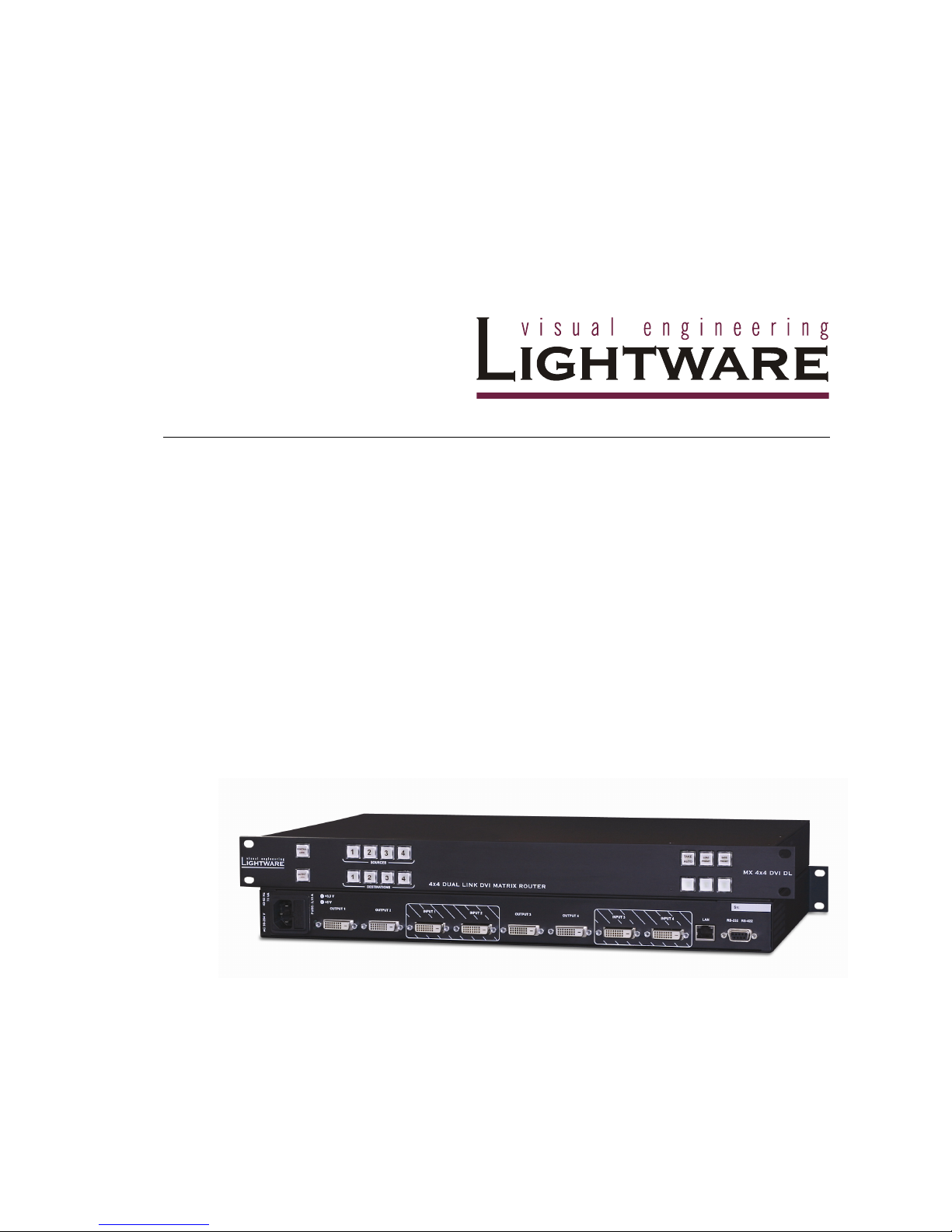
MX4x4DVI
MX4x4DVI-DL
User's Manual
.....
Page 2
Version 1.0 Page 2 / 43
SAFETY INSTRUCTIONS
Class I apparatus construction. This equipment must be used with a main power system with
a protective earth connection. The third (earth) pin is a safety feature, do not bypass or
disable it.
This equipment should be operated only from the power source indicated on the product.
To disconnect the equipment safely from power, remove the power cord from the rear of the
equipment, or from the power source. The MAINS plug is used as the disconnect device, the
disconnect device shall remain readily operable.
There are no user-serviceable parts inside of the unit. Removal of the top cover will expose
dangerous voltages. To avoid personal injury, do not remove the top cover. Do not operate
the unit without the cover installed.
The apparatus shall not be exposed to dripping or splashing and that no objects filled with
liquids, such as vases, shall be placed on the apparatus.
The apparatus must be safely connected to multimedia systems. Follow instructions
described in this manual.
Rep l acin g the AC f use
Unplug the AC power cord from the equipment
Locate the AC fuse on the rear of the unit (page 4)
Replace only the AC fuse as indicated on the rear panel of the unit: 3.15A fast
blowing
Connect the power cord to the switcher and to the AC power source. Make sure
the switcher is working properly.
WEEE
( Was t e El e c tric a l & E l ectr o nic E q uipm e n t)
Corr e ct Di s posa l of T h is Pr o duct
This marking shown on the product or its literature, indicates that it should not be
disposed with other household wastes at the end of its working life. To prevent
possible harm to the enviroment or human health from uncontrolled waste disposal,
please separate this from other types of wastes and recycle it responsibily to promote
the sustainable reuse of material resources.
Household users should contact either the retailer where they purchased this
product, or their local government office, for details of where and how they can take
this item for environmentally safe recycling.
Business users should contact their supplier and check the terms and conditions of the purchase
contract. This product should not be mixed with other commercial wastes for disposal.
Page 3

MX4x4DVI-DL
User’s Manual
Page 3 / 43
DECLARATION OF CONFORMITY
We,
Lightware Kft. 1071 Budapest Peterdy str. 15 HUNGARY
as manufacturer declare, that the product
MX4x4DVI
MX4x4DVI-DL
(Computer Matrix Switcher)
in accordance with the EMC Directive 49/336/EEC and the Low Voltage Directive
73/23/EEC amended by the CE-marking Directive 93/64/EEC are in conformity with
the following standards:
EMI/EMC .................... EN 55103-1 E3, EN 55103-2
Safety .......................................... EN 60065 Class I
Date: 20th Februarry 2007
Name: Gergely Vida ( Managing Director )
Signed:
Page 4

Version 1.0 Page 4 / 43
Table of contents
Page 5

MX4x4DVI-DL
User’s Manual
Page 5 / 43
1. General description
Lightware MX4x4DVI ( single link) and MX4x4DVI-DL ( dual link ) is a DVI matrix switcher
with 4 DVI inputs and 4 DVI outputs, that routes any input(s) to any combination of output(s).
The router conforms to DVI 1.0 specification, and switches signals between 25 - 165 MHz
pixel clock frequency: from 640x480@60Hz to 1920x1200@60Hz or 2048x1080@60Hz PC
resolutions single link, and up to 3440x2400 pixel in dual link mode.
The input signal is not equalized, therefore only standard length (max 5 meter) DVI cables
can be used.
The switcher has an RS 232 ( or RS422 optional) and an RJ45 LAN port for remote control
applications and a control panel for local control operation. Front panel buttons are
illuminated and easy field relegendable with text for informative system integration.
Box cont ents
Routing switcher
User's manual
IEC power cable
RS 232 9 pole D-sub Male to Female cable
CD-ROM with control software
Page 6

Version 1.0 Page 6 / 43
Fea t ures
4 Inputs, 4 Outputs non-blocking cross point matrix architecture - The router
allows any input to be switched to any output or more outputs
simultaneously.
Single link, max 1.65 Gb/s DVI-D transmission (1920x1200 or 2048x1080) -
The MX 4x4 DVI routes any DVI single link signal between 25
and 165 MHz pixel clock frequency conforming to DVI 1.0
standard, MX4x4DVI and MX4x4DVI-DL models
Dual link, max 1.65 Gb/s DVI-D transmission (2560x1600 or 3840x2400) - The
MX 4x4 DVI DL routes any DVI single link or dual link signal
between 25 and 165 MHz pixel clock frequency conforming to
DVI 1.0 standard. MX4x4DVI-DL model only.
Supports all HDTV resolutions: 720p, 1080i and 1080p etc. without HDCP
encoding - Unencrypted HDTV signals up to 165 MHz pixel
clock frequency regardless of resolution are passed through
MX 4x4 DVI
EDID routing - Advanced EDID management with EDID emulation. The user can
emulate any EDID on the switcher's inputs independently, read
out and store any attached monitor's EDID in 100 internal
memory locations, upload and download EDID.dat files using
Remote Control Software.
Front panel buttons control – 4 source select, 4 destination select, Take, Load
preset, Save preset, Panel Lock, Output Lock
Relegendable buttons – Each button has an easy removable flat cap and a
translucent label which can be inserted under it to identify
sources and destinations.
RS 232 or RS422 control – Simple ASCII based RS232 protocol is used for
switching, preset calling, status request, etc.
Ethernet control - TCP/IP Ethernet 10Base-T or 100Base TX (Auto-Sensing)
Fiber cable support – Self powered DVI fiber cables using +5V from DVI sources
( VGA cards, etc.) usually are consuming more than 50 mA,
which load is maximum allowed by DVI 1.0 standard.
MX 4x4 DVI & DL supports +5V 500 mA constant current output
on each DVI output to power long distance fiber optical cables.
Universal power supply – the unit accepts AC voltages from 100 to 240 Volts
with 50 or 60 Hz line frequency on standard IEC connector.
Power failure memory – In case of power failure the unit stores its latest
configuration, and after next power up it loads automatically.
Page 7
MX4x4DVI-DL
User’s Manual
Page 7 / 43
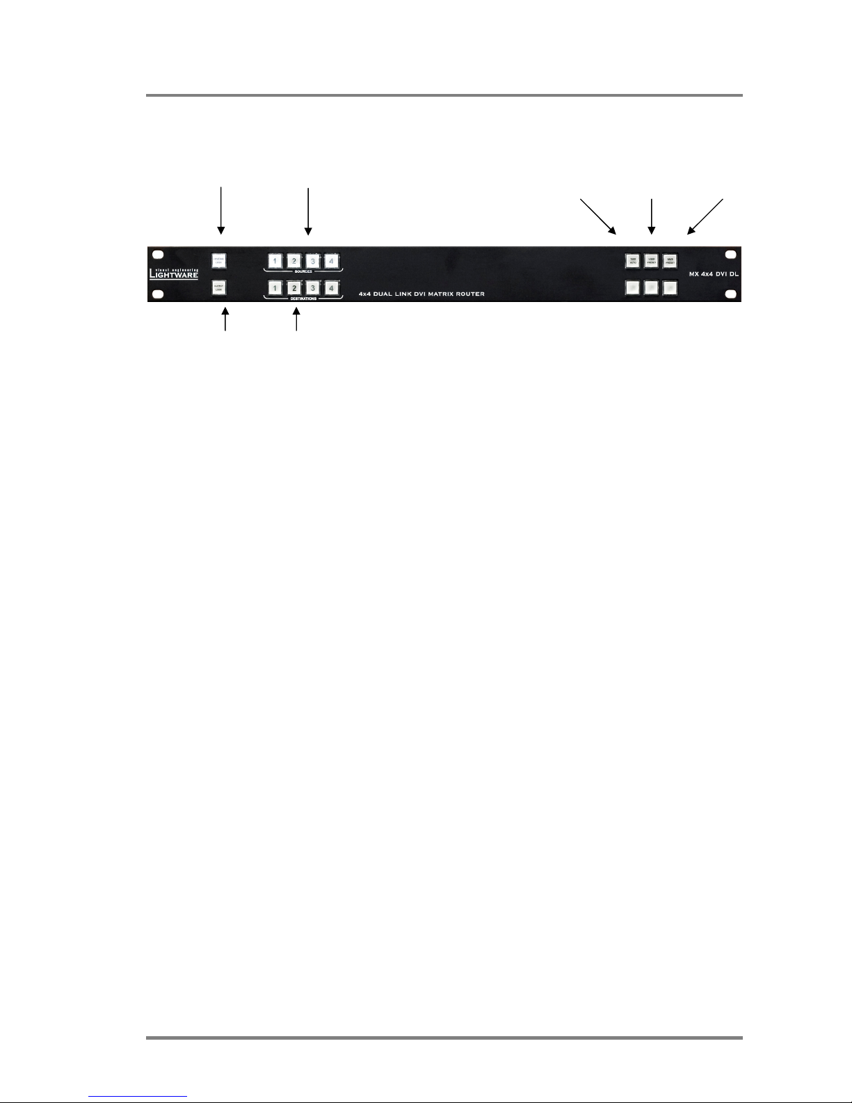
Fro nt Pa nel v iew
CONTROL LOCK Sources 1 to 4 Take/ Load Save
Autotake Preset Preset
OUTPUT LOCK Destinations 1 to 4
Control Lock Disables or enables front panel operation. When red
illuminated, operations on front panel are prohibited.
Output Lock Locks and protects one ( or more ) outputs. Inhibits accidental
input changing on protected output.
Sources Source buttons have three functions: to select an input, to
select a preset and to view the selected input’s state (take
mode).
Destinations Destination buttons have two functions: to select an output, or
to view the selected output’s state.
Take/Autotake This button has two functions: displays the actual switching
mode of the router or executes switching on TAKE mode.
Load Preset Loads and executes a previously saved preset from one of the
preset memories.
Save Preset Stores actual matrix state, in one of preset memories.
Page 8
Version 1.0 Page 8 / 43
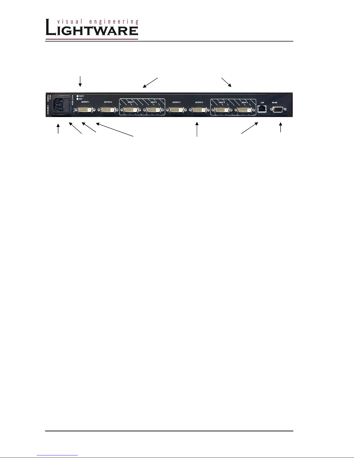
Rea r Pan el vi ew
Signal presence LED-s INPUT connectors 1 to 4
AC Power AC DC Power OUTPUT Connectors1 to 4 Ethernet RS 232/422
connector Fuse LED's control port port
AC Power Standard IEC power connector. The router works with 90 to 264
Volts, 50 or 60 Hz power sources.
RS 232/422 connector 9 pole Dsub female connector for remote control applications.
Can be ordered with RS232 or RS422 control.
Ethernet port RJ 45 connector. Remote control port for connecting the unit to
Local Area Network.
Input connectors 24 pole DVI–D digital only female receptacle connectors.
Connect DVI sources devices to these connectors.
Output connectors 24 pole DVI–D digital only female receptacle connectors.
Connect DVI monitors or other displays to these connectors.
Power LED's Indicators for presence of internal DC voltages +3.3 Volts and +
5 Volts
Page 9
MX4x4DVI-DL
User’s Manual
Page 9 / 43
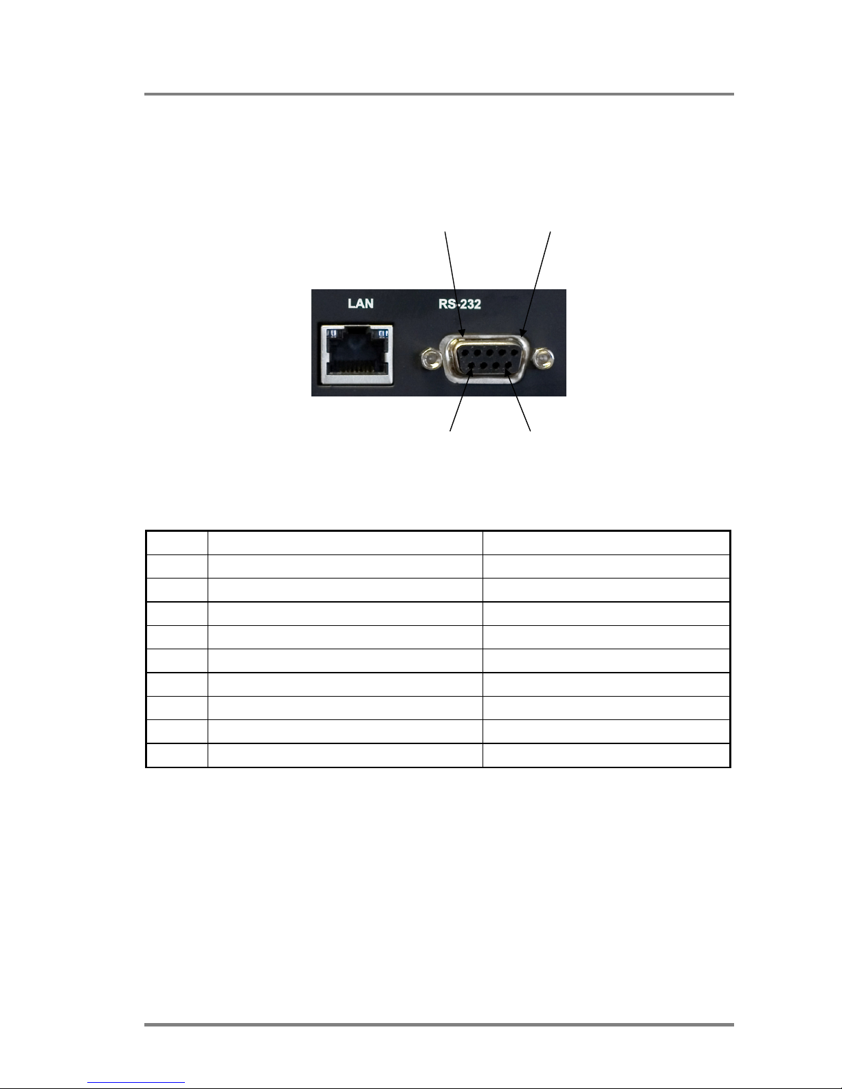
RS 232/4 2 2 co ntrol port
Lightware MX 4x4 DVI and MX 4x4 DVI DL can be remote controlled through
industry standard 9 pole sub-D female connector located on the rear panel of the
unit.
The router can be ordered with RS232 or RS422 control port.
Pin 5 Pin 1
Pin 9 Pin6
RS 232 port pin locations
Table1. - RS232 and RS422 pin connections
Pin nr. RS 232 RS 422
1
NC non connected TX- data transmit complement
2
TX data transmit TX+ data transmit true
3
RX data receive RX+ data receive true
4
DTR internally connected to Pin 6 RX- data receive complement
5
GND signal ground (shield) GND signal ground (shield)
6
DSR internally connected to Pin 4 NC non connected
7
RTS internally connected to Pin 4 NC non connected
4
CTS internally connected to Pin 7 NC non connected
9
NC non connected NC non connected
Page 10
Version 1.0 Page 10 / 43
DVI inpu t s
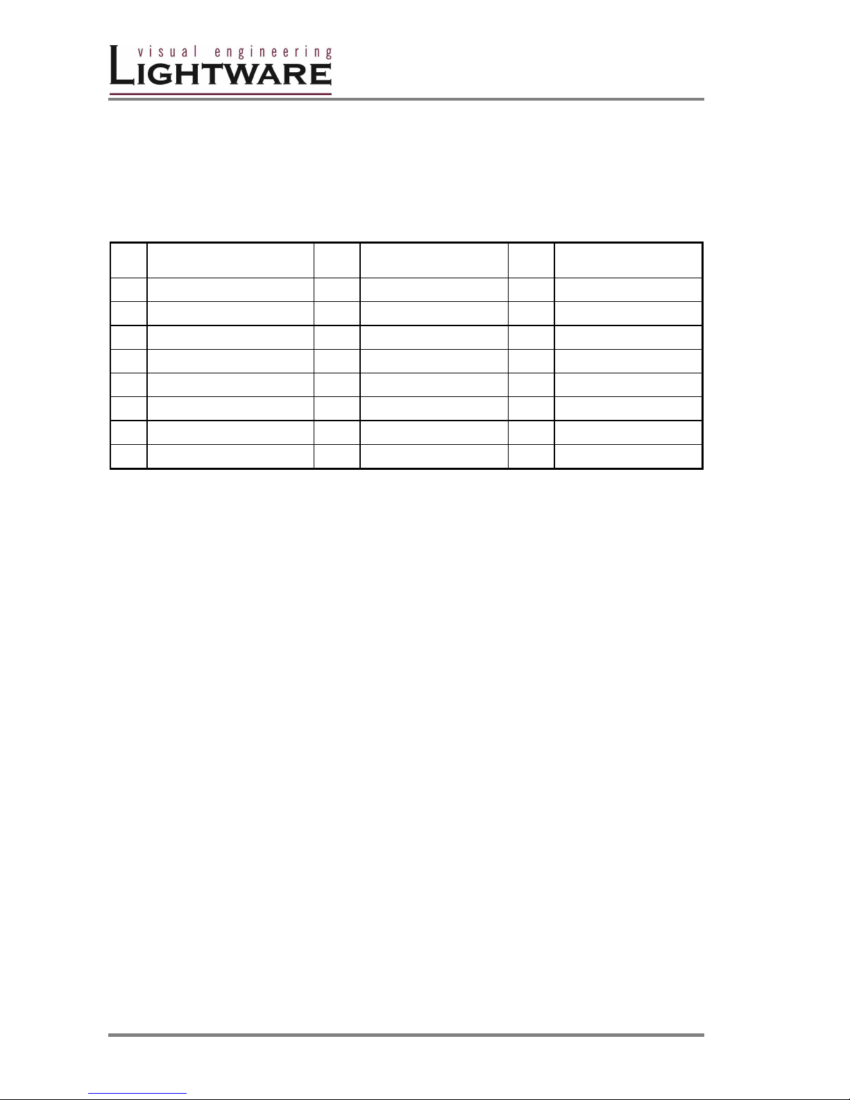
MX4x4DVI and MX4x4DVI-DL provides 24 pole „digital only” DVI-D connectors for
input connections. Always use high quality DVI cable for connecting sources and
displays.
Pin Signal Pin Signal Pin Signal
1
TMDS Data2-
9
TMDS Data1-
17
TMDS Data0-
2
TMDS Data2+
10
TMDS Data1+
18
TMDS Data0+
3
TMDS Data2/4 Shield
11
TMDS Data1 Shield
19
TMDS Data0 Shield
4 TMDS Data4- 12 TMDS Data3- 20 TMDS Data5-
5 TMDS Data4+ 13 TMDS Data3+ 21 TMDS Data5+
6
DDC Clock
14
+5V Power
22
TMDS Clock Shield
7
DDC Data
15
GND (for +5V)
23
TMDS Clock+
8
nc
16
Hot Plug Detect
24
TMDS Clock-
Table2. - DVI-D digital only connector Single Link / Dual link pin assignments
DVI outp uts
MX 4x4 DVI and MX 4x4 DVI DL provides 24 pole "digital only” DVI-D connectors
for output connections. As standard DVI outputs, there can be used limited length
cables, since there is no output amplification applied. For using longer cable runs
at outputs, use fiber optical DVI cables or active DVI repeaters/extenders.
Fibe r Ca ble p oweri ng
As special feature MX4x4DVI and MX4x4DVI-DL on DDC +5V output (pin 14 on
output connectors) is able to supply 500 mA current to power fiber optical DVI
cables. Standard DVI outputs or graphics cards supply only 55 mA current on +5V
output, thus unable to power directly a fiber optical cable.
Info MX4x4DVI and MX4x4DVI-DL does not check if the connected sink (monitor,
projector or other equipment) supports Hotplug or EDID signals but outputs the
selected signal immediately after switch command.
Page 11

MX4x4DVI-DL
User’s Manual
Page 11 / 43
EDI D MAN AGEM E NT
Each DVI sink ( eg. monitors, projectors, plasma displays, switcher inputs) must
support the EDID data structure. Source BIOS and operating systems are likely to
query the sink using DDC2B protocol to determine what pixel formats and interface
is supported. DVI standard makes use of EDID data structure for the identification
of the monitor type and capabilities. Most DVI sources (VGA cards, set top boxes,
etc) will output DVI signal after accepting the connected sink’s EDID information. In
case of EDID readout failure or missing EDID the source will not output DVI video
signal.
MX4x4DVI and MX4x4DVI-DL provides an advanced EDID Management feature
with advanced functions that helps system integration. The built in EDID Router
stores and emulates 100 EDID data and all monitor's EDID's that are connected to
the output connectors. 50 EDID's are factory presets, while memories 50 to 99 are
user programmable.
On all inputs there can be emulated different or same EDID's, that are copied from
EDID router's memory, or the attached monitor. For example, the router can be set
up to emulate any device, that is connected to one of the inputs, and the EDID is
automatically changed, if the monitor is replaced with an other.
EDID Router can be controlled with included Matrix Control Software via RS232
port or Ethernet.
Page 12

Version 1.0 Page 12 / 43
2. Operation
POWE R
Connect the power cord to the router’s IEC standard power input connector. The
unit is immediately powered on when the power cord is connected to the AC
source. The router does not have a power switch, it remains powered on, until AC
line voltage is present.
After powered on, the unit performs a self test, all front panel buttons light up for
one second. After the self test the router reloads its last configuration and it is
ready for use.
Info At switching on, the router reloads the latest settings which were used before it
was turned off. The unit has an internal emergency memory which stores all
current settings, and ties configurations. This memory is independent from presets
and invisible for the user. This built-in feature helps the system to be ready
immediately in case of power failure or accindentally powering down.
FRO N T PANEL OP ERATI ONS
TAKE / AUTOTAKE modes
The router has two different switching modes: TAKE and AUTOTAKE. If the TAKE
button is unlit, TAKE mode is active. When the TAKE button is continuously lighting
green, AUTOTAKE mode is selected.
Press and hold the TAKE button for two seconds to change between TAKE and
AUTOTAKE modes.
TAKE mode allows the user to make multiple connections and deselections at
once. This mode is useful when time delay is not allowed between multiple
switchings.
AUTOTAKE mode is useful when immediate actions must be done or fast
switching is needed between sources on a destination.
CONTROL LOCK
Front panel button operations can be enabled or disabled using CONTROL LOCK
button, while RS232/422 or LAN control is still enabled. If it unlits, front panel
button operations are enabled. If there is a coninuous red lighting, front panel
operations are inhibited.
Press and release CONTROL LOCK button to toggle the control lock state.
Page 13

MX4x4DVI-DL
User’s Manual
Page 13 / 43
SWITCHING
Creating a connection or multiple connections in TAKE mode
1. First press and release the selected source button. The pressed source
button and all destination buttons which are currently connected to this
source will light up. The dark remaining destination buttons are not
connected to this source. This is an informative display about current status
of the selected input. (view only)
2. Press and release the selected destination button or buttons which has to be
connected to the selected source. The preselected destination button(s)
start blinking.
3. Press and release TAKE button to execute the tie or ties. Now the selected
input is switched to the selected output or to the multiple outputs.
Deselecting or muting in TAKE mode
1. First press and release the selected source button. The pressed source
button and all destination buttons which are currently connected to this
source will light up. The dark remaining destination buttons are not
connected to this source. This is an informative display about current status
of the selected input. (view only)
2. Press and release the selected, green lighting destination button which has
to be disconnected from the selected source. The pressed destination or
multiple destinations will turn dark.
3. Press and release TAKE button to execute disconnection.
Info Deselected destinations are disconnected from any source, thus output devices
will display black image or "no signal" message, or automatically will turn off.
Info Multiple switching and deselecting actions can be done simultaneously, during only
one TAKE action.
Creating a connection in AUTOTAKE mode
1. Press and release the selected destination button. The pressed destination
button, and the actually connected source button are lighting green. If no
source is connected ( the output is muted) no source button will light.
2. Press and release the selected input button. The switch action will be
executed immediately. Switching between sources to the selected
destination can be done directly.
Deselecting or muting in AUTOTAKE mode
1. Press and release the selected destination button. The pressed destination
button, and the actually connected source button are lighting green. If no
source is connected ( the output is muted) no source button will light.
Page 14

Version 1.0 Page 14 / 43
2. Press and release the active green lighting source button. The output is
muted.
Info Deselected destinations are disconnected from any source, thus output devices
will display black image or "no signal" message or automatically will turn off.
SAVE or LOAD PRESETS
MX4x4DVI and MX4x4DVI-DL has 4 front panel programmable presets. Each
preset stores a configuration regarding all input connections for all outputs. All
presets are stored in a non volatile memory, the router keeps presets even in case
of power down. Memory numbers are assigned to source buttons 1 to 4
Saving a Preset in TAKE mode
1. Press and release SAVE PRESET button.
2. Press and release the desired source (memory address) button (source 1 to
4)
3. Press and release TAKE button. Now the current configuration is stored in
selected memory.
Info Preset save action always stores the current configuration for all outputs
Loading a Preset in TAKE mode
1. Press and release LOAD PRESET button.
2. Press and release the desired source (memory address) button (source 1 to
4)
3. Press and release TAKE button. Now the selected preset is loaded.
Info Loading a preset always modifies all output states.
Saving a Preset in AUTOTAKE mode
1. Press and release SAVE PRESET button.
2. Press and release the desired source (memory address) button (source 1 to
4). Now the current configuration is stored in the selected memory.
Info Preset save action always stores the current configuration for all outputs .
Page 15

MX4x4DVI-DL
User’s Manual
Page 15 / 43
Loading a Preset in AUTOTAKE mode
1. Press and release LOAD PRESET button.
2. Press and release the desired source (memory address) button (source 1 to
4). Now the selected preset is loaded.
Info Loading a preset always modifies all output states.
VIEW current state
User can check the current switching status on the front panel using front panel
buttons. View mode is slightly different in TAKE or AUTOTAKE modes because of
different switching philosopy of the two modes.
Info View mode does not mean, that the router has to be switched in different mode,
viewing and switching can be done after each other, without pressing any special
button.
View current state in TAKE mode
If the router is in TAKE mode, user can verify both input and output connections. In
TAKE mode no accidental change can be done unless TAKE button is pressed.
Press and release a source button. Now the selected source button and all
destination buttons will light up which are currently connected to the selected
source. This informative display will remain for 5 seconds, then turns all buttons
unlit.
If all source and destination and TAKE buttons are unlit (the unit is in TAKE mode,
and no input was selected in last 5 seconds), press and release a destination
button to see its current state. Now the source button which is connected to the
selected destination will light up. If no source button is lighting, the selected
destination is in muted state. Pressing another destination button, there can be
seen the last pressed state of destination.
View current state in AUTOTAKE mode
In AUTOTAKE mode only states of destination can be viewed.
Press and release the required destination button. Now the source button which is
connected to the selected destination will light up. If no source button is lighting,
the selected destination is in muted state. Pressing another destination button,
there can be seen the last pressed current state of destination.
Page 16

Version 1.0 Page 16 / 43
OUTPUT LOCK
Using the router there is a possibility to lock a destination. This feature prevents an
accidental switching to the locked destination in case of important signal. Locking a
destination means, that no input configuration can be changed or deselected on
that particular destination.
Destinations can be indepentently locked or unlocked. Locking a destination does
not affect other destinations.
Output Lock in TAKE mode
1. Press and release the required destination button. Now the selected
destination button and the currently configured source button will light up
(view mode)
2. Press and release the Output Lock button. Now the Output Lock button will
light up in red colour.
3. Press and release TAKE button. The desired destination now is locked.
Unlock in TAKE mode
1. Press and release the required destination button which was previously
locked. Now the selected destination button and the currently configured
source button and the Output Lock button will light up.
2. Press and release the Output Lock button (deselect). Now the Output Lock
button will turn off, however the locking function has not been unlocked yet.
3. Press and release TAKE button. The desired destination now is unlocked.
Output Lock in AUTOTAKE mode
1. Press and release the required destination button. Now the selected
destination button and the currently configured source button will light up
(view mode)
2. Press and release the Output Lock button. Now the Output Lock button will
light up in red colour, and lock function is activated. No source can be
changed at the locked destination.
Unlock in AUTOTAKE mode
1. Press and release the required destination button which was previously
locked. Now the selected destination button and the currently configured
source button and the Output Lock button will light up
2. Press and release the Output Lock button (deselect). Now the Output Lock
button will turn off, and the locking function has been unlocked.
Page 17

MX4x4DVI-DL
User’s Manual
Page 17 / 43
3. RS 232 / 422 control
RS232 / RS422 ports
MX 8x8 DVI can be ordered with either RS232 or RS422 communication port. The
port settings are done in the factory. D-sub connector pin assignments can be
found on chapter 1.
Changing and viewing protocols
MX4x4DVI and MX4x4DVI-DL is equipped with multiple router protocols.
1. Switch the router in TAKE mode if used prevoiously in AUTOTAKE mode by
pressing TAKE button for 2 seconds. ( TAKE will not light continuously)
2. Press and release Control Lock ( Control Lock button lights in red colour
continuously)
3. Press and keep pressed Output Lock button. Now one of the source buttons
will light up ( view protocol)
If Source#1 button lights: Lightware protocol is active
If Source#2 button lights: Protocol#2 is active
4. During Output Lock pressed, press the desired Source button, accordingly to
the new protocol. The desired Source button starts blinking, and then the
router lights up all buttons for 4 seconds. Now the new protocol is active.
Port settings:
The device uses standard RS-232 interface with the following settings:
9600 Baud
8 data bit
1 stop bit
no parity
null modem cable
The matrices accept commands surrounded by curly brackets - { } - and responses
surrounded by round brackets - ( ) - only if a command was successfully executed.
Input, output numbers and values must be sent as two digit ASCII numbers.
Page 18

Version 1.0 Page 18 / 43
Control commands:
Legend : xx* = input number in 2 digit ASCII format (01,05,07 etc.)
yy* = output number in 2 digit ASCII format
CrLf = Carriage return, Line feed (0x0D,0x0A)
= space character (0x20)
notes:
*
From firmware version 1.13 one digit input, output, and preset numbers are accepted, characters are
case-insensitive
.
1. Switch one input to one output ( Audio / DVI / RGB / SDI / Video)
Command {xx@yy}
Response (OyyIxx)CrLf
Description: Switch input xx to output yy.
Example: Connect input 1 to output 5.
Command {01@05}
Response (O05 I01)CrLf
2. Switch one input to all outputs ( Audio / DVI / RGB / SDI / Video)
Command {xx@O}
Response (IxxAll)CrLf
Description: Switch input xx to all outputs.
Example: Switch input 1 to all outputs.
Command {01@O}
Response (I01 All)CrLf
3. View connection on the specified output ( Audio / DVI / RGB / SDI / Video)
Command {?yy}
Response (OyyIxx)CrLf
Description: View connection on output yy.
Example: View connection on output 5.
Command {?05}
Response (O05 I01)CrLf
Page 19

MX4x4DVI-DL
User’s Manual
Page 19 / 43
4. View connection on all outputs ( Audio / DVI / RGB / SDI / Video)
Command {VC}
Response (ALLO1O2O3O4O5O6O7O8)CrLf
Description: Response length depends on the number of outputs installed in the
router. The response above suppose a router having 8 outputs. Indexes show the
actual output and the number at the given index shows which input it is connected
to. If value O5 equals 04 it means that output 5 is connected to input 5.
O1..O8 are two digit ascii characters. (01, 02, 04, etc.)
Example: View connection on output 5.
Command {?05}
Response (O05 I01)CrLf
5. View mutes on all outputs( Audio / DVI / RGB / SDI / Video)
Command {VM}
Response (MUTM1M2M3M4M5M6M7M8)CrLf
Description: Response length depends on the number of outputs installed in the
router. The response above suppose a router having 8 outputs. Indexes show the
actual output and the number at the given index shows its state. If the value M5
equals 1 it means that output 5 is in mute, if 0 output 5 is not muted.
Example:
Command {?M}
Response (MUT 1 0 0 1 0 0 0 0)CrLf
Legend: Current router has 8 outputs. Output 1 and 4 are muted while the other
outputs are unmuted.
6. Mute specified output ( Audio / DVI / RGB / SDI / Video)
Command {#yy}
Response (MUTyy)CrLf
Description:Mute output yy.
Example:Mute output 5.
Command {#05}
Response (MUT05)CrLf
7. Unmute specified output ( Audio / DVI / RGB / SDI / Video)
Command {+yy}
Response (UMTyy)CrLf
Description: Unmute output yy.
Example: Unmute output 5. Output 5 is now switched to the output it was
connected prior to mute command.
Command {+05}
Response (UMT05)CrLf
Page 20
Version 1.0 Page 20 / 43
8. Save preset to the specified memory position ( Audio / DVI / RGB / SDI / Video)
Command {$zz}
Response (SPRzz)CrLf
Description:Save current ties to preset zz.
Example:Save current connections to preset memory 7.
Command {$07}
Response (SPR07)CrLf
9. Load preset from the specified position ( Audio / DVI / RGB / SDI / Video)
Command {%zz}
Response (LPRzz)CrLf
Description: Load current ties to preset zz.
Example: Load connections previously saved to preset memory 7. All connections
will be reloaded.
Command {%07}
Response (LPR07)CrLf
10. View product type ( Audio / DVI / RGB / SDI / Video)
Command {I} - capital i
Response (PRODUCT_TYPE)CrLf
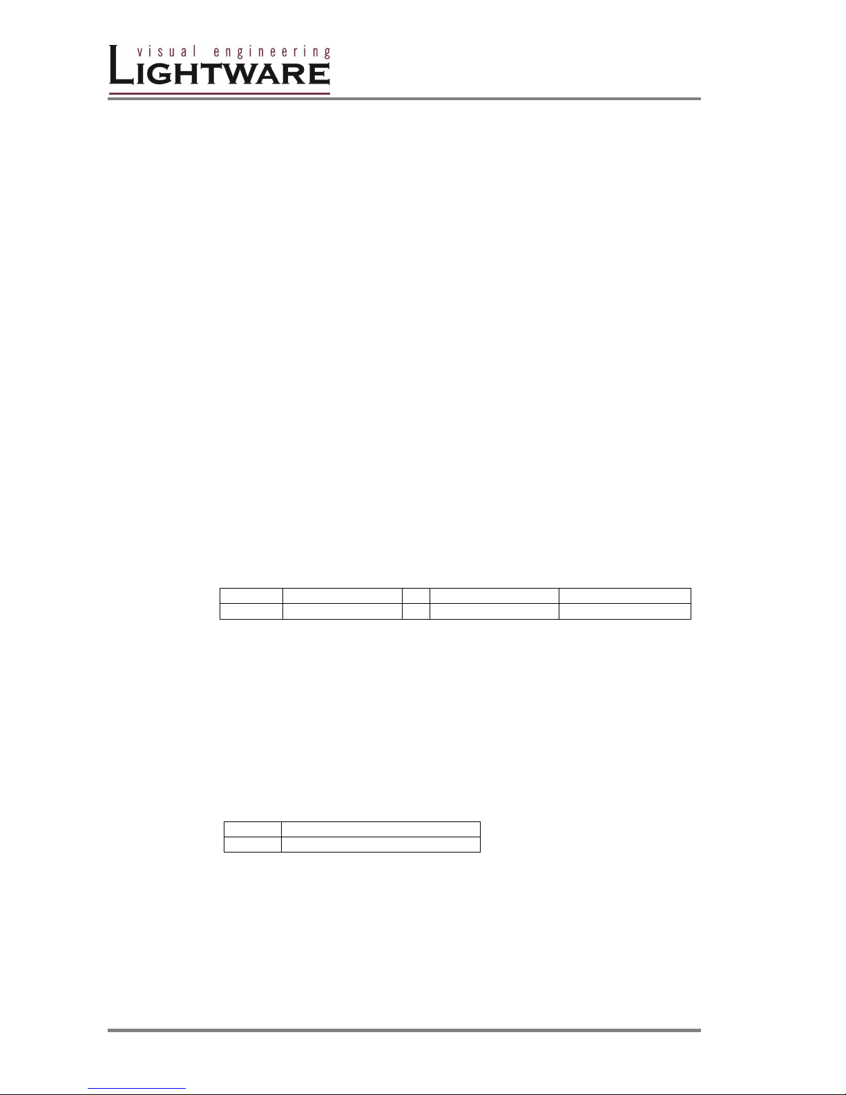
Description: DEVICE_NAME format:
Example:
Command {I}
Response (MX8X8DVI)CrLf
The connected router has 8 inputs, 8 outputs and it is a DVI router.
11. View serial number ( Audio / DVI / RGB / SDI / Video)
Command {S}
Response (SERIAL_NUMBER)CrLf
Description: SERIAL_NUMBER format:
Example:
Command {S}
Response (SN:06050100)CrLf
The connected serial number of the router is: 06050100.
Number of inputs
Number of Outputs Device type
MX
X
A,DVI,RGB,SDI,V
8 -1byte long- ASCII numbers
SN:
xxxxxxxx
Page 21

MX4x4DVI-DL
User’s Manual
Page 21 / 43
12. View Firmware version ( Audio / DVI / RGB / SDI / Video)
Command {F}
Response (FIRMWARE_VERSION)CrLf
Example:
Command {F}
Response (FW:1.11)CrLf
The connected router has a firmware version of 1.11.
13. Error responses ( Audio / DVI / RGB / SDI / Video)
Invalid input number
Response (ERR01)CrLf
Description: Given input number exceeds the installed number of inputs or equals
zero.
Invalid output number
Response (ERR02)CrLf
Description: Given output number exceeds the installed number of outputs or
equals zero.
Invalid value
Response (ERR03)CrLf
Description: Given value exceeds the maximum allowed value to be sent.
Invalid preset number
Response (ERR04)CrLf
Description: Given preset number exceeds the maximum allowed preset number.
The maximum preset number is limited to 32 for all matrices.
Page 22
Version 1.0 Page 22 / 43
4. Software control - Lightware Matrix Controller
The unit can be controlled using Lightware Matrix Controller from a PC computer or Laptop
through RS 232 or Ethernet port.
4.1 INSTALLING MATRIX CONTROLLER
Info Windows firewall should be switched off to enable the IP search feautre!
Info If older version of control software is installed please uninstall it before installing a
newer version (see section 7.)
Info The control software requires Java runtime environment v1.5 or higher. This can be
found in the supplied CD’s Java Installer directory, or downloaded from Sun’s
website:
http://dlc.sun.com/jdk/jre-1_5_0_01-windows-i586-p.exe
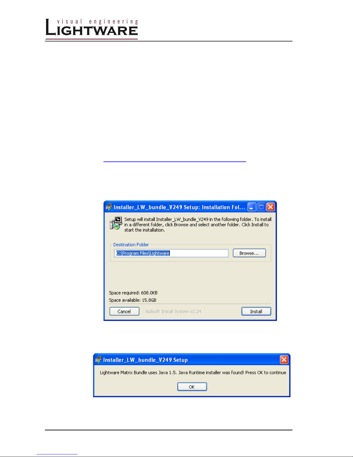
1. Run Installer_LW_bundle_v x.xx.exe
(x.xx refers to actual revision - currently v 2.49)
2. Select destination folder and click Install (Using the default path is highly
recommended)
3. If Java is already installed the following pop-up window will appear:
4. Click OK button.
Page 23
MX4x4DVI-DL
User’s Manual
Page 23 / 43
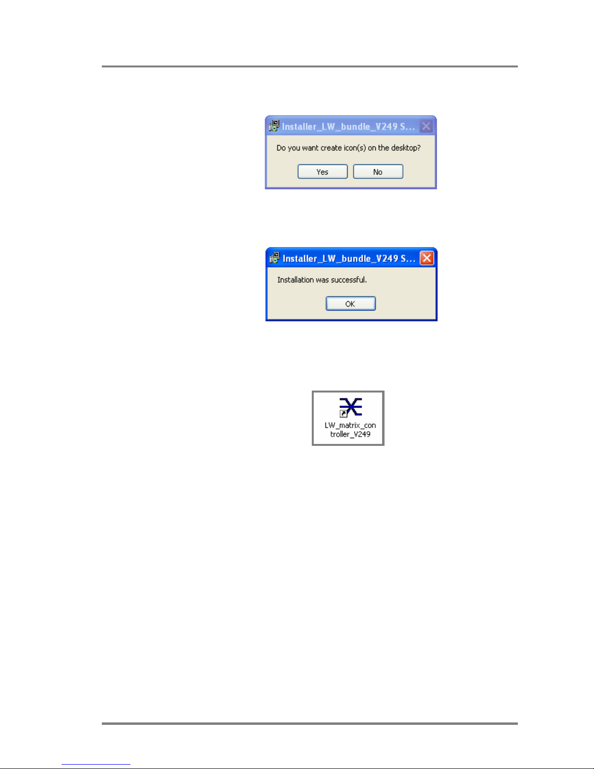
5. If you want to create desktop icon click Yes in the next pop-up window:
6. After finishing the installation of Lightware Matrix Controller the following
message appears:
7. To run Lightware matrix control software find and click from Start menu-
>Programs->Lightware->LW_matrix_controller_vXXX.jar or from the
desktop ikon (if this option was selected) via shortcut:
8. To uninstall the control software double click on: Start menu ->Programs-
>Lightware-> Uninstall_LW_matrix_controller_vXXX.exe
Page 24
Version 1.0 Page 24 / 43
4.2 Using Lightware Matrix Controller
The unit can be controlled using Lightware Matrix Controller software from a PC
computer or Laptop through RS 232 connection or Ethernet port.
1. Connection between the Matrix switcher and the computer can be made via
− serial port, with standard RS232 Male to Female cable
− Ethernet ( with a HUB or to a simple endpoint)
− Ethernet directly ( with cross UTP cable)
2. Starting the application
To run the CONTROL SOFTWARE double click on
LW_matrix_controller_vXXX icon on the desktop or select from Startmenu-
>Programs->Lightware-> LW_matrix_controller_vXXX.jar)
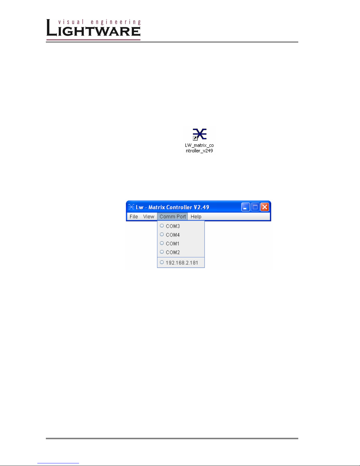
3. Select communication interface according to your actual connection:
RS232 If the connection has been made via serial port, select the
appropriate communication port from Comm Port drop-down menu.
IP If the connection has been made via ethernet select the desired IP
address from Comm Port drop-down menu. No IP addresses will be shown if
no Lightware LAN enabled matrix switcher is connected to the same network
as the PC.
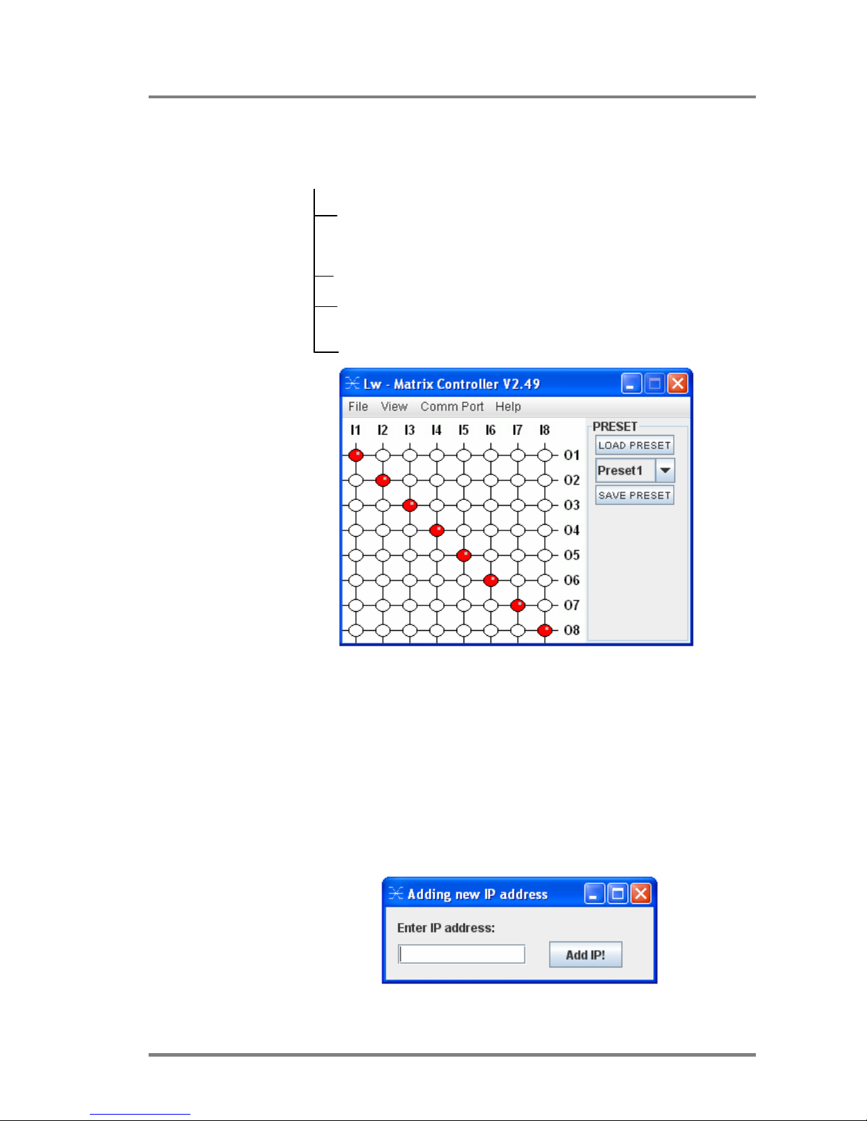
4. When the Lightware Matrix Controller finds the hardware, it defines the
product type, and a button matrix area appears according to the input and
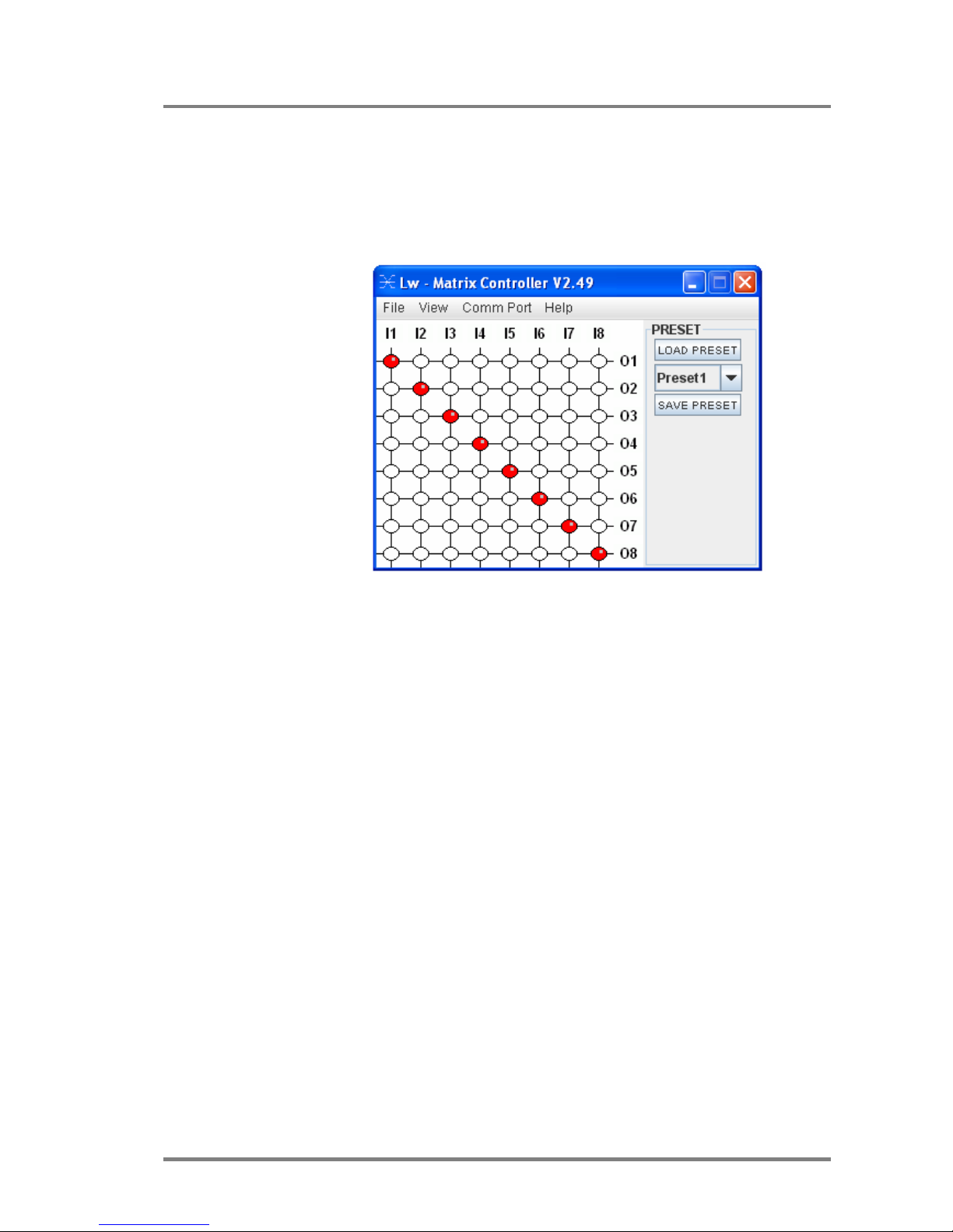
output numbers of the router.I1; I2; I3...columns are representing the inputs,
the O1; O2; O3...rows the outputs. Each red bulb represents a valid
connection.
Info After starting the Lightware Matrix Controller, it automatically searches for
Lightware devices connected to the LAN. If finds one picks its IP address and puts
into the Comm Port menu. If there are no matrix switchers connected to the PC
only comm ports will be shown in this menu.
Info Windows firewall should be switched off to enable the IP search feautre!
Info Only one user is allowed to connect to the matrix switcher via ethernet.
Info After a successful connection has been established to a matrix switcher there is no
difference in control via serial port and ethernet.
Page 25
MX4x4DVI-DL
User’s Manual
Page 25 / 43
MENU Description
Matrix Controller contains following menus and submenus:
LW Matrix Controller
File
-Synchronize matrix
-Add new IP address
-Exit
View
-Edid router
Comm Port
-Serial ports
-IP addresses
Help
File menu
File menu contains 3 items:
Synchronize matrix
Selecting Synchronize matrix will re-read connection
information from the router and refresh the display.
Add new IP address
Selecting Add new IP address will display a new
window where the user can add IP addresses of routers
that are not in the same subnet.
Write a valid IP address and click Add IP!
Exit
Exit will terminate the application.
Page 26
Version 1.0 Page 26 / 43
View menu
View menu contains 1 item:
Edid router window
This item is gray and can not be selected if the connected MS does
not have EDID ROUTER installed. For more information see Section:
EDID operation
Comm Port menu
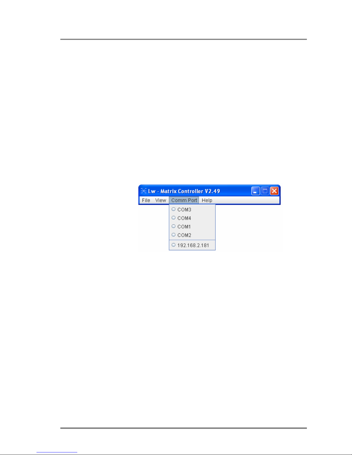
Comm Port menu contains 2 sections:
Serial ports available on the current PC
IP addresses found on the network
The IP addresses displayed in this window are those Lightware
products, that are connected to the network. More than one units can
be connected to one Local Area Network
HELP menu
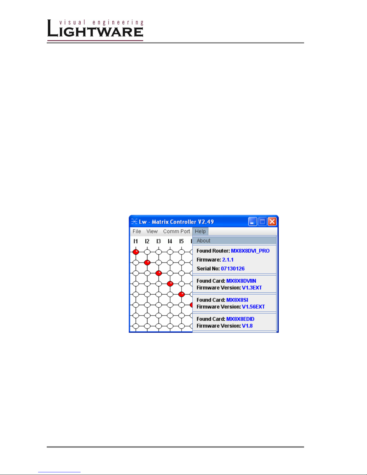
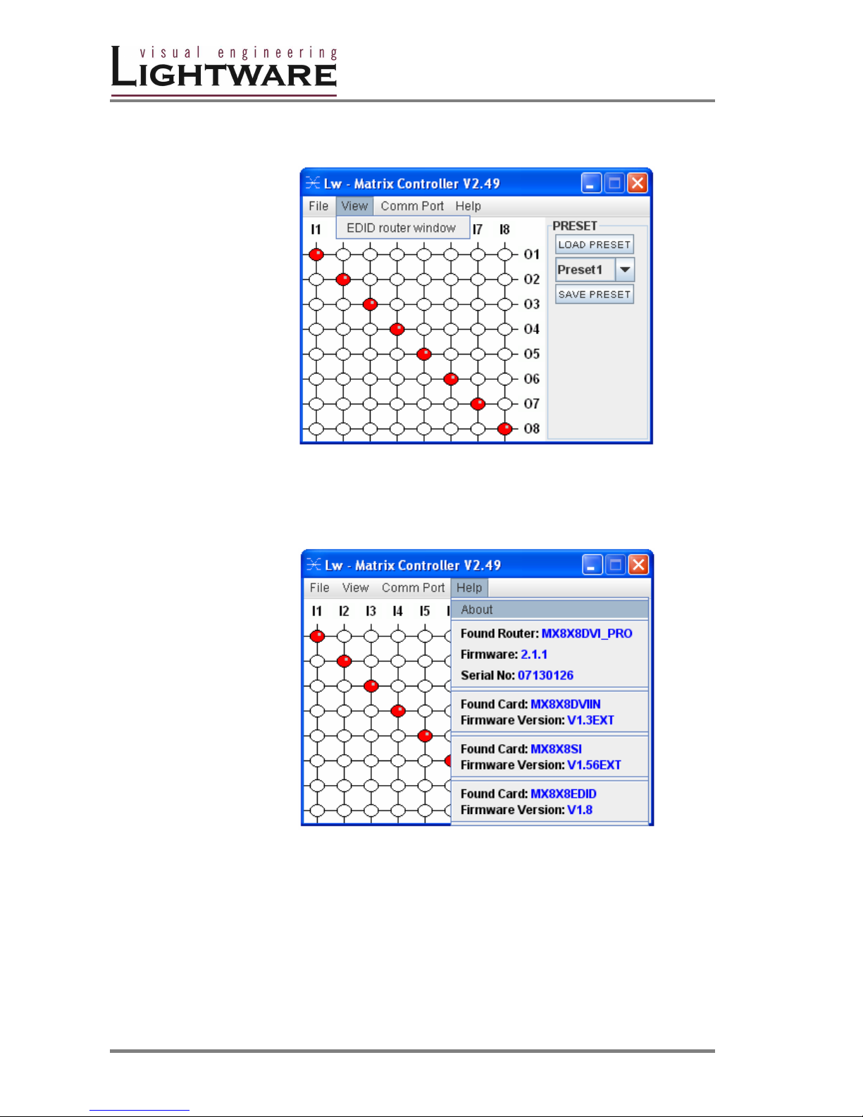
After a successful connection to a Lightware router all identifying information is
shown under the Help menu.
The connected matrix router’s name (MX8x8DVI_PRO), installed firmware revision
(2.1.1) and serial number (format: year and week of production, and the serial
number, which is also found at back of the unit) can be seen in the first section.
The following sections contain information about the installed cards.
Page 27
MX4x4DVI-DL
User’s Manual
Page 27 / 43
I/O switching
I1; I2; I3...columns are representing the inputs, the O1; O2; O3...rows the outputs.
Each red bulb represents a live connection.
For making a connection click on the desired empty bulb.
PRESET operations
Preset operations can be done via the right panel named PRESET. Each
Lightware matrix switcher has 32 preset memories, that can be loaded and saved
any time.
Front panel Preset operations effect only the first 8 preset memories, all others
from 9 to 32 are available only via Matrix Controller software.
Info A Preset setting stores a full configuration of all outputs, that effects all outputs,
when loading a Preset.
SAVE PRESET
1. Make the desired configuration on matrix switching area.
2. Select the preset memory ( Preset1...Preset32) where you want to save your
current configuration
3. Press SAVE PRESET button. Now the preset is stored.
LOAD PRESET
1. Select the preset memory ( Preset1...Preset32) you want to load as next
configuration
2. Press LOAD PRESET button. Now the preset is loaded
3. On the matrix switching area there is displayed the new I/O configuration
Page 28
Version 1.0 Page 28 / 43
RENAME a preset:
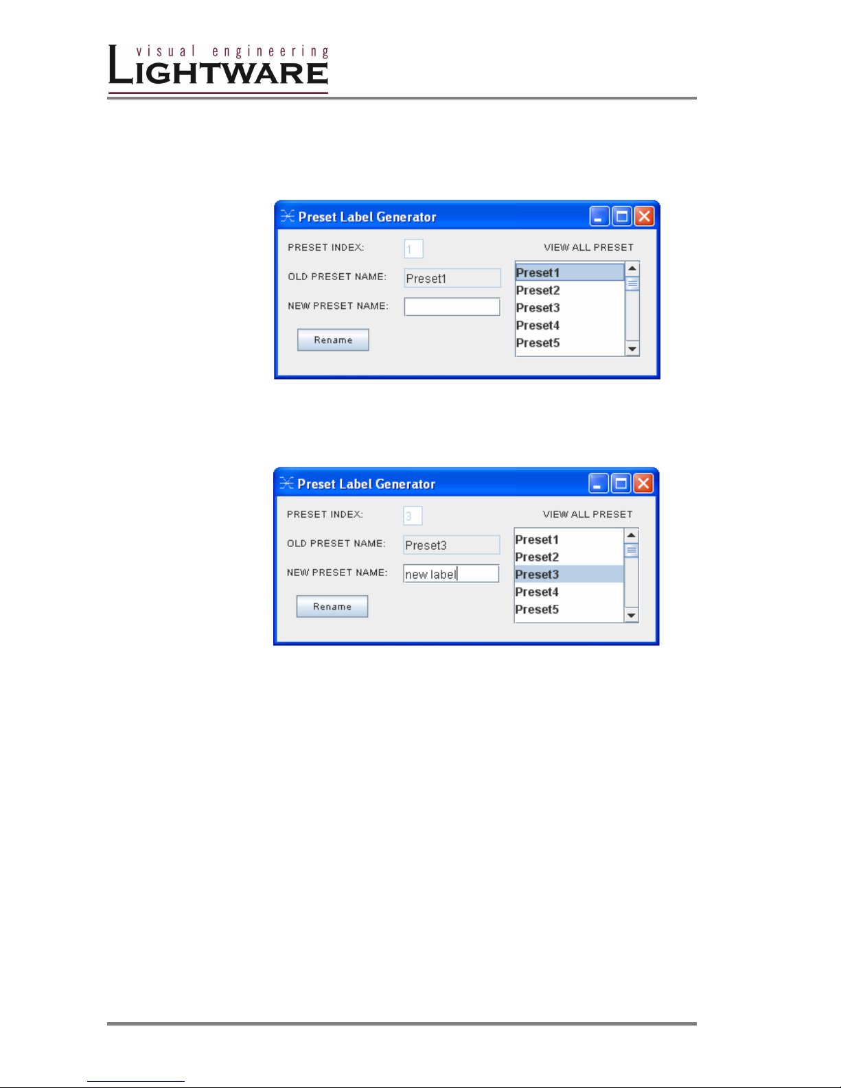
Each preset has its own label (by default: Preset1..Preset32) which can be
renamed. To modify these labels right-click on the preset list. The following window
appears:
Example:
Select Preset3 and type the new preset name "new label", and click rename. The
new name appears in the list. Close this window.
Page 29

MX4x4DVI-DL
User’s Manual
Page 29 / 43
4.3 EDID Management: using EDID Router
Each DVI sink ( eg. monitors, projectors, plasma displays, switcher inputs) must
support the EDID data structure. Source BIOS and operating systems are likely to
query the sink using DDC2B protocol to determine what pixel formats and interface
is supported. DVI standard makes use of EDID data structure for the identification
of the monitor type and capabilities. Most DVI sources (VGA cards, set top boxes,
etc) will output DVI signal after accepting the connected sink’s EDID information. In
case of EDID readout failure or missing EDID the source will not output DVI video
signal.
Why is EDID management necessary?
All DVI sources must read attached sink’s EDID data (switcher input, monitor input,
etc.) before starting the DVI signal transmission. If no EDID is available, most
sources will not output the signal. Unlike in standard analog VGA graphics cards,
DVI graphics cards do not allow to be forced from Windows
desktop/properties/settings tab to different pixel resolutions. Only those resolutions
and refresh rates are allowed, which are defined in EDID data.
To provide proper EDID data for DVI sources MX 8x8 DVI PRO has an advanced
built in EDID router, that can manage the emulated EDID on it’s all inputs
indpendently. EDID can be managed using Lightware Matrix Controller software
from a PC computer or Laptop through RS232 connection or Ethernet port.
Emulating the right EDID information helps the user and installation engineer to
control overall system’s signal properties
EDID emulating options are:
1 emulating an EDID from factory preset memory ( 50 EDID) – static
EDID emulation
2 emulating an EDID from user preset memory ( 50 memory
locations) – static EDID emulation
3 copying and emulating EDID from one of attached display devices
- dynamic EDID emulation
With EDID Router function the user is able to store EDID from any attached
monitor to one of the user programmable memories, to download EDID from file to
user memory, and to upload EDID from the router to file.
Info User must not disconnect DVI cables to change an EDID opposite to other
manufacturer’s products. EDID can be changed even if source is connected to the
input and powered ON .
Info When EDID has been changed, the router toggles the HOTPUG signal for 200
msec. Some graphic cards or DVD players do not sense the hotplug signal, and
there can be happen, that even if EDID has been changed, the new set resolution
is not affected. This case the source device must be restarted, or powered OFF
and ON again.
Page 30
Version 1.0 Page 30 / 43
About EDID router
EDID router contains a 116 block non volatile memory bank. EDID List is structured
as follows:
1..50 .....................................................................Factory Preset EDID list
51..100 ........................................................User programmable memories
101..108 ( DVI_OUT_1...8) ............................Attached monitor’s EDID list
109..116 ( DVI_IN_1...8).......................emulated EDID at input conenctors
Info The first 50 EDID (1…50 inclusive) are factory preprogrammed and cannot be
modified. These are the most commonly used resolutions.
Info The attached monitor’s EDID is stored automatically, until a new monitor is
attached to that particular output. In case of powering the unit off, the last attached
monitor’s EDID remains in non volatile memory.
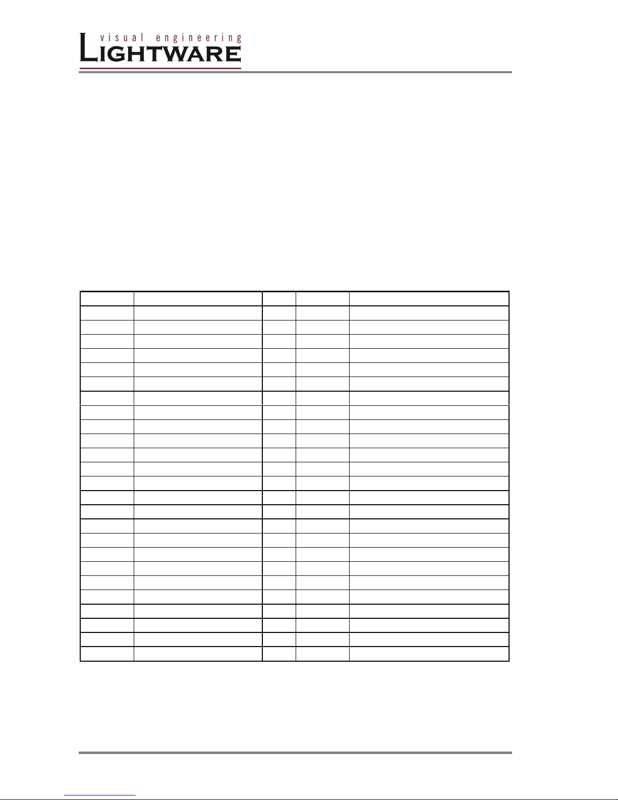
Table4. -Factory Preset EDID list
MEMORY Resolution MEMORY Resolution
01 640x480@60 Hz
26 1600x1200@60 Hz
02 640x480@75 Hz
27 1920x1200@60 Hz
03 848x480@60 Hz 16:9
04 800x600@50 Hz
05 800x600@60 Hz
30 720x480p@60 Hz
06 800x600@75 Hz
31 576i@50 Hz
07 1024x768@50 Hz
32 720x576p@50 Hz
08 1024x768@60 Hz
33 1280x720p@50 Hz
09 1024x768@75 Hz
34 1280x720p@60 Hz
10 1152x864@75 Hz
35 1920x1080i1 @50 Hz
11 1280x768@50 Hz
36 1920x1080i2 @50 Hz
12 1280x768@60 Hz
37 1920x1080i@60 Hz
13 1280x768@75 Hz
38 1920x1080p@24 Hz
14 1360x768@60 Hz
39 1920x1080p@25 Hz
15 1364x768@50 Hz
40 1920x1080p@30 Hz
16 1364x768@60 Hz
41 1920x1080p1 @50 Hz
17 1364x768@75 Hz
42 1920x1080p2 @50 Hz
18 1280x1024@50 Hz
43 1920x1080p@60 Hz
19 1280x1024@60 Hz
44 2048x1080p1 @50 Hz
20 1280x1024@75 Hz
45 2048x1080p2 @50 Hz
21 1366x1024@60 Hz
46 2048x1080p@60 Hz
22 1400x1050@50 Hz
47
23 1400x1050@60 Hz
48
24 1400x1050@75 Hz
49
25 1600x1200@50 Hz
50
Page 31
MX4x4DVI-DL
User’s Manual
Page 31 / 43
EDID Router operation
Connecting to the MATRIX SWITCHER
1. Install CONTROL SOFTWARE. (See Section Software Installation)
2. Connect the Matrix switcher to the pc via Serial Port, or Ethernet (with a
HUB or to a simple endpoint) or with Ethernet directly (with X cable)
3. Open the CONTROL SOFTWARE from Start Menu->Lightware-
>LW_MATRIX_CONTROLLER_Vxxx, where xxx means the latest software
revision.
Info The actual revision of the CONTROL SOFTWARE is 2.51
2. Select communication interface:
If you connect via serial port select the appropriate port from drop-down
menu under Comm Port, and click on it.
If you want to connect via ethernet then you can also find IP address(es) in
this drop-down menu. No IP addresses will be shown if no Lightware LAN
enabled matrix switcher is connected to the same network as the PC.
Info After starting the CONTROL SOFTWARE, it automatically searches for matrix
switchers on the LAN. If finds one, it’s IP address will be displayed in the Comm
Port menu. If there are no matrix switchers connected to the PC only comm ports
will be shown in this menu.
Info Only one user is allowed to connect to one matrix switcher via ethernet.
Info After a successful connection has been established to a matrix switcher there is no
difference in control via serial port and ethernet.
Page 32
Version 1.0 Page 32 / 43
4. After the MATRIX CONTROLLER found the hardware a button matrix should
appear. Select View->EDID router window.
Info After a successful connection all identifying information is shown under the Help
menu.
Page 33
MX4x4DVI-DL
User’s Manual
Page 33 / 43
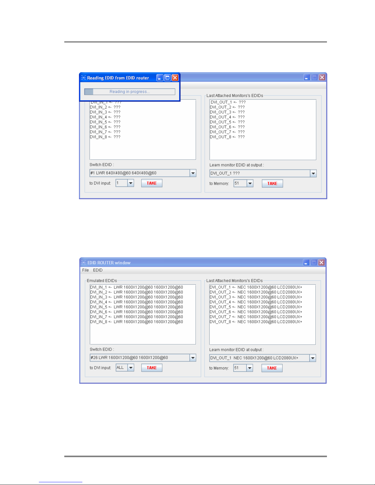
5. The EDID ROUTER window appears and the software starts to synchronize
EDID list with the Matrix switcher.
6. After synchronization process the current status of the MATRIX SWITCHER
EDID are shown on the two text area. The Emulated EDID window contains
the resolutions and the vendor names of the EDID reported to the PC for
each input separately. The Last Attached Monitor’s EDID window contains
the resolutions and vendor names of the display devices connected to matrix
switcher’s output.
Page 34
Version 1.0 Page 34 / 43
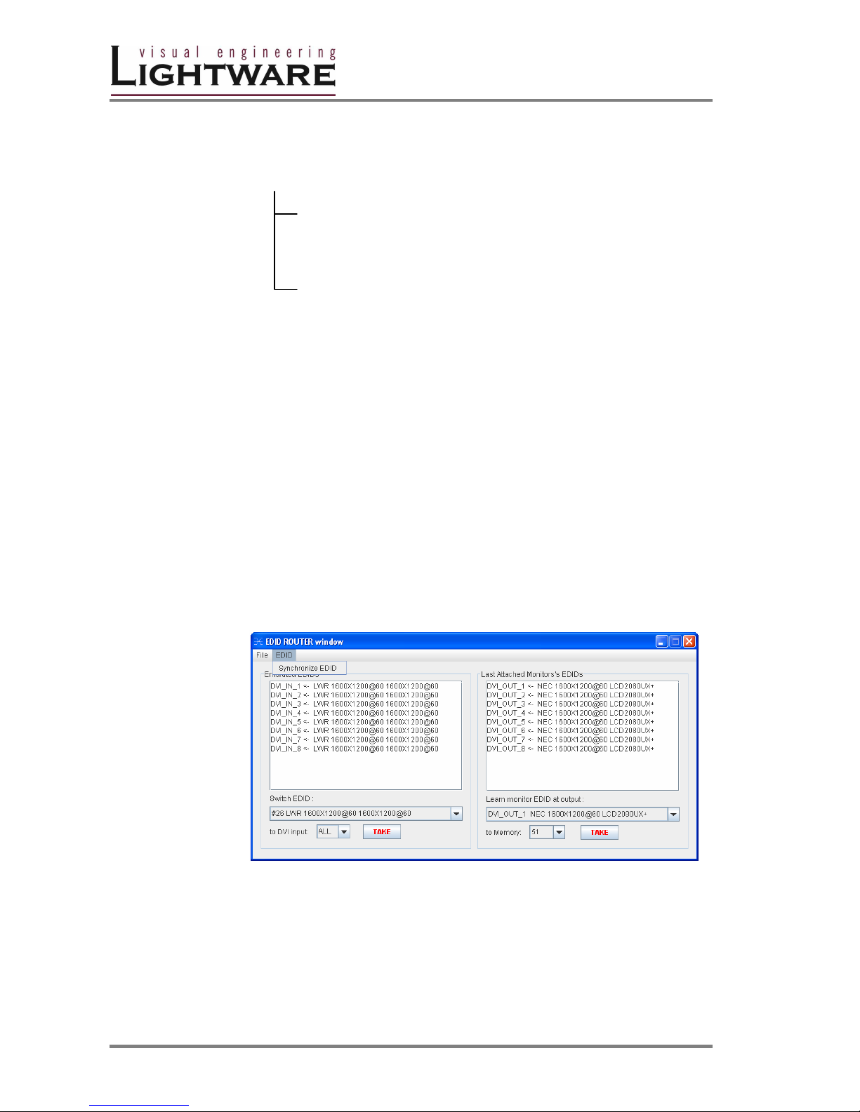
EDID ROUTER MENU Description
EDID Router window contains following menus and submenus:
EDID ROUTER
File
-Download EDID from file to memory
-Upload EDID from memory to file
-Close EDID ROUTER window
EDID
-Syncronize EDID
EDID menu
EDID menu contains 1 section:
Syncronize EDID
Selecting Synchronize EDID menu the Lightware Matrix Controller
(PC) software rereads all EDID information from the connected
MATRIX SWITCHER. While normal operation it is not necessary to
use this menu item because the MATRIX SWITCHER always
automatically reports every status change.
Info There is always a small delay in responses. So if a new monitor is connected to the
output its new EDID is not shown immediately but in 2 seconds!
Info As the MATRIX SWITCHER reports status change nothing will happen if you select
the same EDID to a given input or connect the same display device to a given
output!
Page 35
MX4x4DVI-DL
User’s Manual
Page 35 / 43
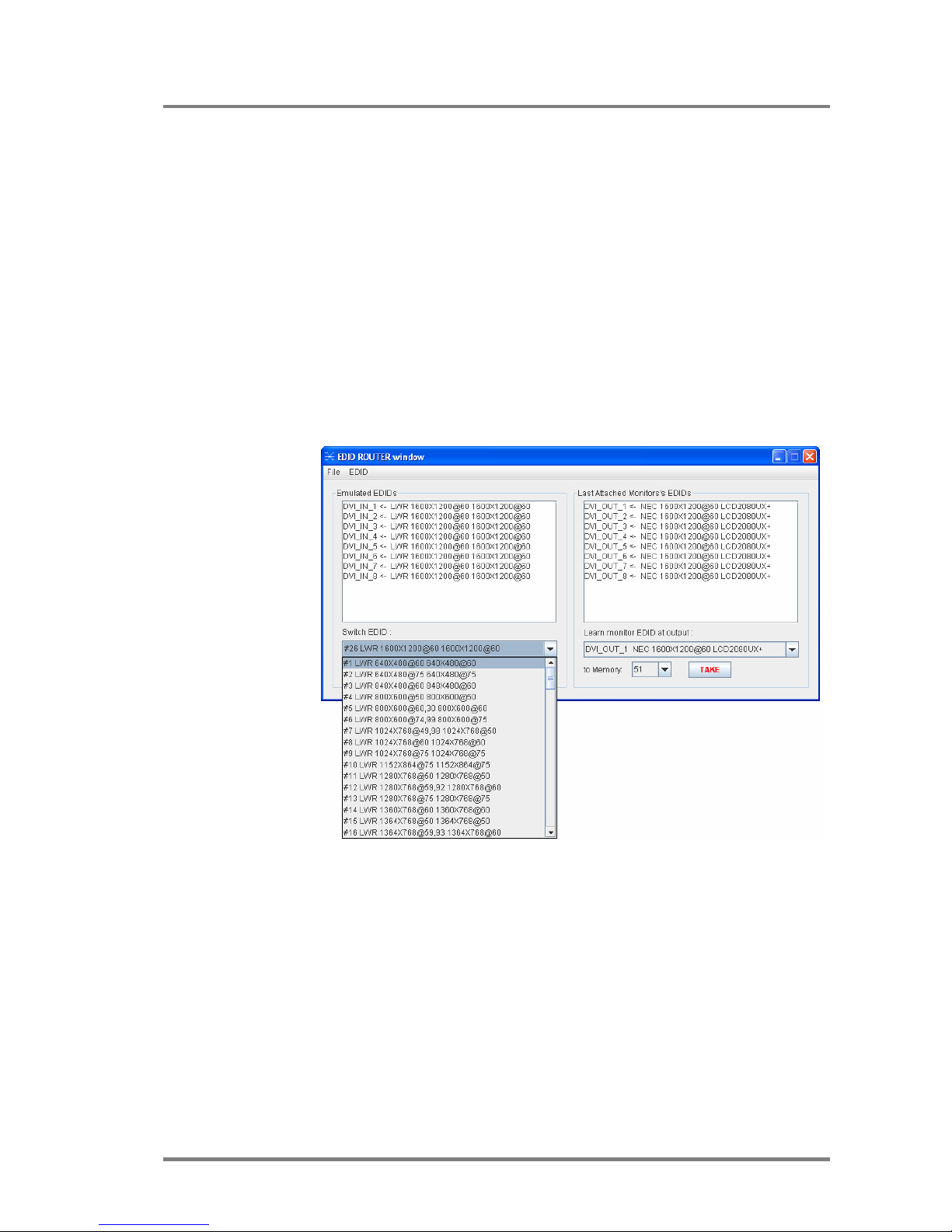
Change emulated EDID at one or all inputs
All EDID are enumerated in the switch EDID list. If you want to modify the current
emulated resolution you can select one from this list. There is static EDID
emulation or dynamic EDID emulation.
- Static EDID emulation means, when an EDID from memories 01..100 is
selected and emulated at input(s)
- Dynamic EDID emulation occurs, when an attached monitor’s EDID is
emulated at input(s), simply copying the data from the monitor. This EDID
changes automatically, if a new monitor is attached to the output.
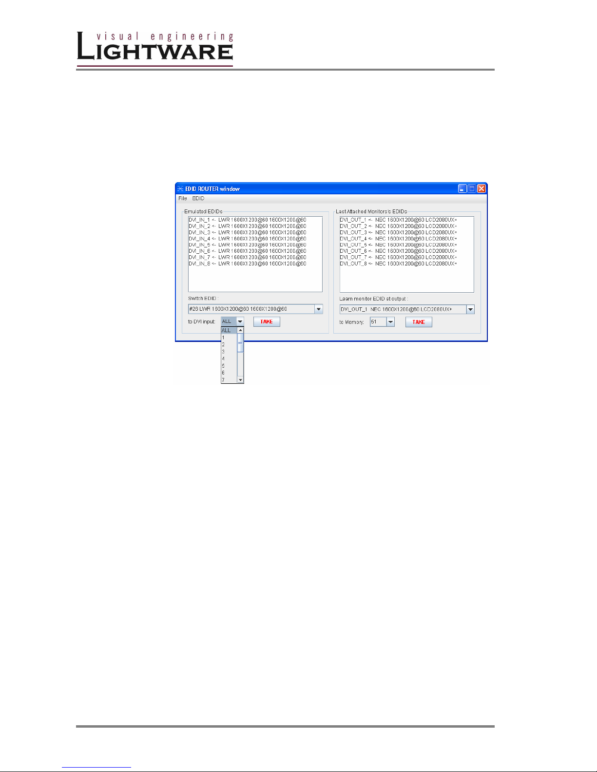
1. Select the desired EDID from Switch EDID list ( from #1..100 through
DVI_IN_1 ..to DVI_IN_8)
Page 36
Version 1.0 Page 36 / 43
2. Select the output ( or ALL outputs) where the desired EDID will be emulated
3. Press TAKE button. Now the EDID has been changed on selected input(s).
After selecting a new EDID from the switch EDID list, selecting a output (or
the ALL item) and pressing the TAKE button the MATRIX SWITCHER will
modify that (or all) input(s) EDID. This procedure causes a status change
and hence it is reported back to the CONTROL SOFTWARE within 2
seconds.
Info If a monitor’s EDID was selected to emulate ( DVI_OUT_1 to ..8) the emulated
EDID will be changed all times on thet input(s), when a new monitor was
connected. If the monitor was disconnected from output, the latest EDID remains, it
will not be deleted from input. This feature helps especially rental technicians or
system integrators to keep the source continuously transmitting the signal, and
adopt the system for new incoming display devices.
Info Power ON/OFF cycle will not effect the emulated EDID or other settings.
Info EDID switch procedure causes a status change and hence it is reported back to
the CONTROL SOFTWARE within 2 seconds.
Page 37
MX4x4DVI-DL
User’s Manual
Page 37 / 43
Learn EDID from attached display device
The MATRIX SWITCHER can learn the EDID from the connected display device
and store it in one of user programmable memory.
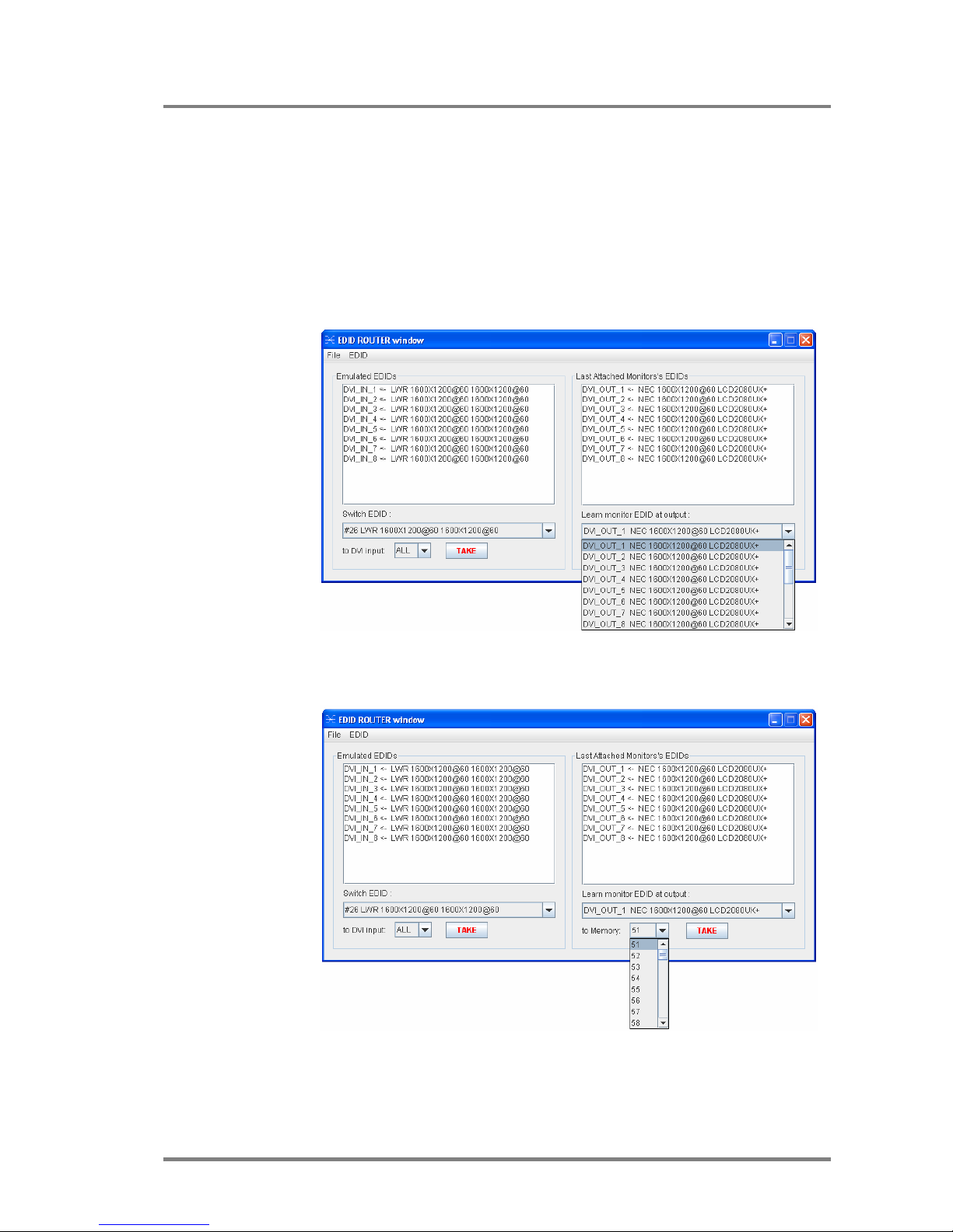
All EDID is enumerated in the „Learn monitor EDID at output” list according to the
router’s outputs.
1. Select the desired display’s EDID from the list.
2. Choose a memory location from the to Memory list where the EDID will be
stored. Only memories 50...100 are available for user.
3. Press TAKE button. Now the EDID is stored in Matrix non volatile memory.
This procedure causes a status change and hence it is reported back to the
MATRIX CONTROL SOFTWARE within 2 seconds
Page 38
Version 1.0 Page 38 / 43
Download EDID from file to memory
The MATRIX SWITCHER is able to learn and store EDID from attached PC
computer. EDID is stored in *.dat files.
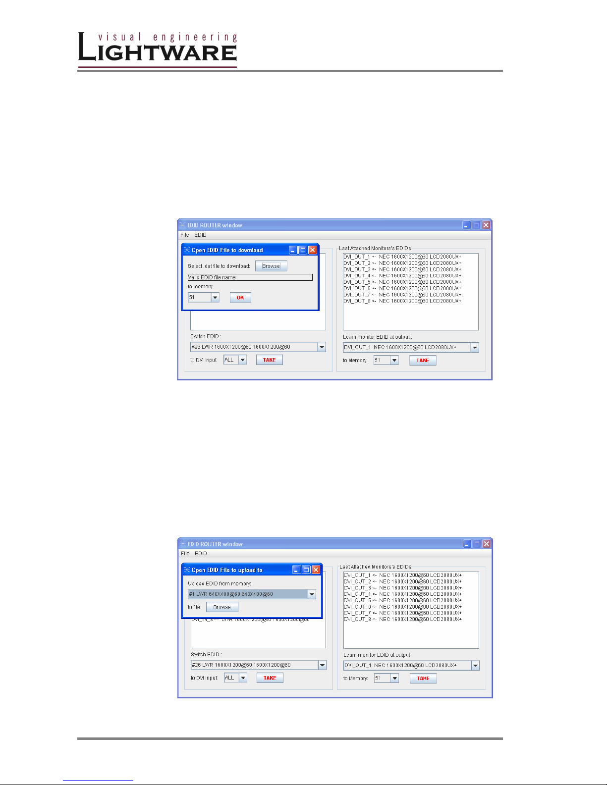
1. Select File-> Download EDID from file to memory.
2. In the pop-up window browse your hard drive to find EDID file. The software
checks if the selected file is a valid EDID file, than continue with step 3.
3. Select a memory location to store the selected EDID. Press ‘OK’ button.
After it was accomplished ”Download Ready” message appears.
Upload EDID from memory to file
The CONTROL SOFTWARE can upload EDID from the MATRIX SWITCHER, and
save it as an EDID file.
1. Select File-> Upload EDID from memory to file.
2. From the pop-up window choose the EDID memory you want to save to file.
3. Click Browse, add a file name and path and click Save. If upload was
successful, an ”Upload Ready ” message confirms the command.
Page 39
MX4x4DVI-DL
User’s Manual
Page 39 / 43
4.4 ERROR Messages
During remote operation there may happen some trouble with the communication.
This cases the Matrix Controller software displays error messages on the screen.
Below there are listed the error messages.
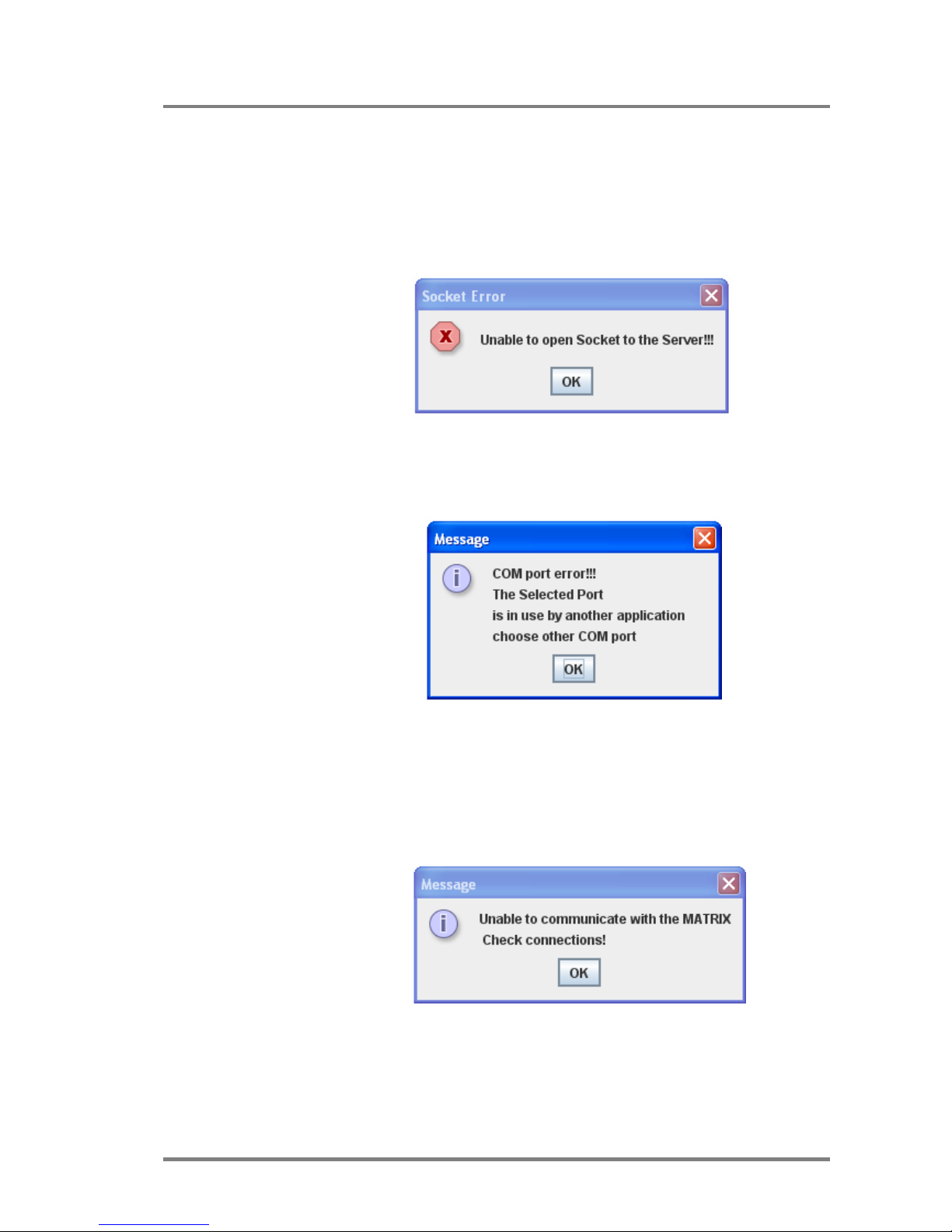
Unable to open Socket to the Server!!!
Trigger: More than one user tries to access the router via LAN.
Explanation: Only one user can connect to the router at once.
COM port error!!!
Trigger: The Matrix Controller software was unable to open the selected serial
communication port on the PC.
Solution: Close any other application that uses the selected port, or try to use
an other serial port. Do not forget to connect the serial lead to the right
connector.
Unable to communicate with the MATRIX
Trigger: No router was found on the specified port,
or a command-response timeout has occurred.
Explanation: The Matrix Controller has tried to access a router on the specified
comm port but no response was received within 2 secs.
Solution: Select the right serial port the router is connected to, or try to do the
last action again.
Page 40

Version 1.0 Page 40 / 43
5. Firmware upgrade
The unit can be upgraded with new firmware versions via RS232 port using a PC computer
or Laptop. Please contact Lightware for the latest firmware version at [email protected]
Before upgrading the new firmware, run the " LW_matrix_bundle.exe " wich installs the
current " Lightware_matrix_controller.jar" and " LW_bootloader_v10.jar " softwares, which
are available from STARTmenu/Lightware location.
The new firmware is a .hex file. The name of the file contains the router type and the
firmware version, ex.: MX4x4DVI_v17.hex
FRONT PANEL ENABLED UPGRADE
Front Panel Enabled Upgrade is the simplest mode for software upgrade. For
preventing unwanted software modifications via RS232 commands, the user must
enable the router using front panel buttons to go in bootloader state. Follow the
steps described below.
1. Connect the RS232 port of the router to the PC RS232 port via null modem
cable.
2. Switch ON the router connecting to the AC power
3. Check if the router is in LW protocol mode: switch the unit in TAKE mode
than lock the panel by pressing CONTROL LOCK. Now theCONTROL
LOCK lights red. Press the OUTPUT LOCK button. During pressed, the
SOURCE1 or SOURCE2 button lights up according to the selected protocol.
If SOURCE1 button lights, LW protocol is selected. Firmware upgrade is
possible.
4. Launch "LW_bootloader_v10.jar" program from
START/Programs/Lightware on you computer
5. Select the desired COM PORT using Com Port menu
6. Open the new firmware file (file name: MX8x8DVI_v17.hex) using File-Open
menu from it's current location
7. Click DOWNLOAD using Firmware menu. Now the computer requests the
router to confirm the firmware upgrade. User must enable the firmware
upgrade pressing front panel buttons as requested on the screen or
described below:
8. Enable Firmware Upgrade: Switch the unit in TAKE mode, than press and
release CONTROL LOCK button. Now Control lock button lights red. Press
and release source buttons 1 than 2 than 3 than 4 after each other. Now the
TAKE, LOAD and SAVE buttons start blinking indicating, that the router is in
bootloader mode. This state will remain until powering down the unit.
9. Start the download process by pressing OK button on the computer. The
download status appears on processbar. Never disconnect the RS232 cable
during firmware upgrade! When download completes, READY message
appeares in red colour.
10. Disconnect the router from AC power, than power it up again. After powering
the unit up, all buttons will light up for a while indicating, that the unit is ready
for operation. In case of failure repeat steps 7 to 10.
Info Once the firmware upgrade failed, the router will NOT indicate it's bootloader
enabled state with TAKE LOAD SAVE buttons blinking, because previous software
has been deleted, but steps 1 to 10 can still be repeated.
Page 41

MX4x4DVI-DL
User’s Manual
Page 41 / 43
5. Specifications
Inputs
DVI input signals ..........................................................................................4x DVI-D
Connectors ........................................................................24 pole DVI-D digital only
Auto equalization: ...................................................................................................No
Input cable equalization: .........................................................................................No
EDID Management .....................................................Yes for each input connector
Signal
Data rate: ...........................................all between 25 Mbps and1.65 Gbps /colour
Channels: ..........................................................1x TMDS Clock + 6x TMDS Colours
Resolutions single link: .....................all between 640x440 and 1920x1200@60Hz
Resolutions dual link: ........................all between 640x440 and 3840x2400@60Hz
Colour depth: ..............................................................................24 bits, 8 bit/colour
HDTV resolutions: ........................................................................720p, 1080i, 1080p
HDCP compliant: ...................................................................................................No
Resolution
Vertical
frequency (Hz)
Horizontal
frequency (KHz)
Pixel Clock
frequency (MHz)
Comment
640x440
60.00 31.47 25.14
DOS VGA
400x600
60.32 37.44 40
VESA SVGA
400x600
75.00 46.47 49.5
VESA SVGA
432x624
74.55 49.72 57.29
MACINTOSH
1240x720
60.00 45.00 74,25
HDTV 720p
1024x764
60.00 44.36 65
VESA XGA
1024x764
75.00 60.02 74.75
VESA XGA
1360x764
47.7 60.00
WIDE-XGA
1152x470
75.06 64.64 100
MACINTOSH
1240x1024
75.00 40.00 135.00
VESA SXGA
1400x1050
60.00 65.64 121.42
SXGA+
1920x1040
60.00 67.50 144.5
HDTV 1040p
2044x1040
60.00 67.50 157.3
2K
1600x1200
60.00 75.00 162
VESA UXGA
1920x1200
60.00 75.00 162
VESA
Table3 - DVI timing examples for some supported resolutions
Outputs
DVI output signals ..........................................................................4x DVI single link
Connectors ........................................................................24 pole DVI-D digital only
Output preemhasis ................................................................................................No
+5V output current ..............................................................500mA continuous each
Page 42

Version 1.0 Page 42 / 43
Control
Front Panel .......................................................................................YES, buttons
Serial Port .......................................................9pole Dsub Female RS232 or RS422
Baud rate .........................................................9600 Baud, 4 bit, 1stop bit, no parity
LAN ..................................TCP/IP Ethernet 10Base-T or 100Base TX Auto-Sensing
General
Power .................................................................. 100-240 V AC 50/60 Hz 1.4..1.0 A
Compliance ...........................................................................................................CE
EMI/EMC ............................................................................EN 55103-1, EN 55103-2
Safety ..............................................................................................EN 60065 Class I
Rack mount ...........................................................................................Yes, 1U high
Enclosure ....................................................................................................... Metal
Enclosure dimensions .....................................44 mm H x 446 mm W x 302 mm D
Weight ...............................................................................................................3kg
Warranty ........................................................................................................ 3 years
Page 43
MX4x4DVI-DL
User’s Manual
Page 43 / 43
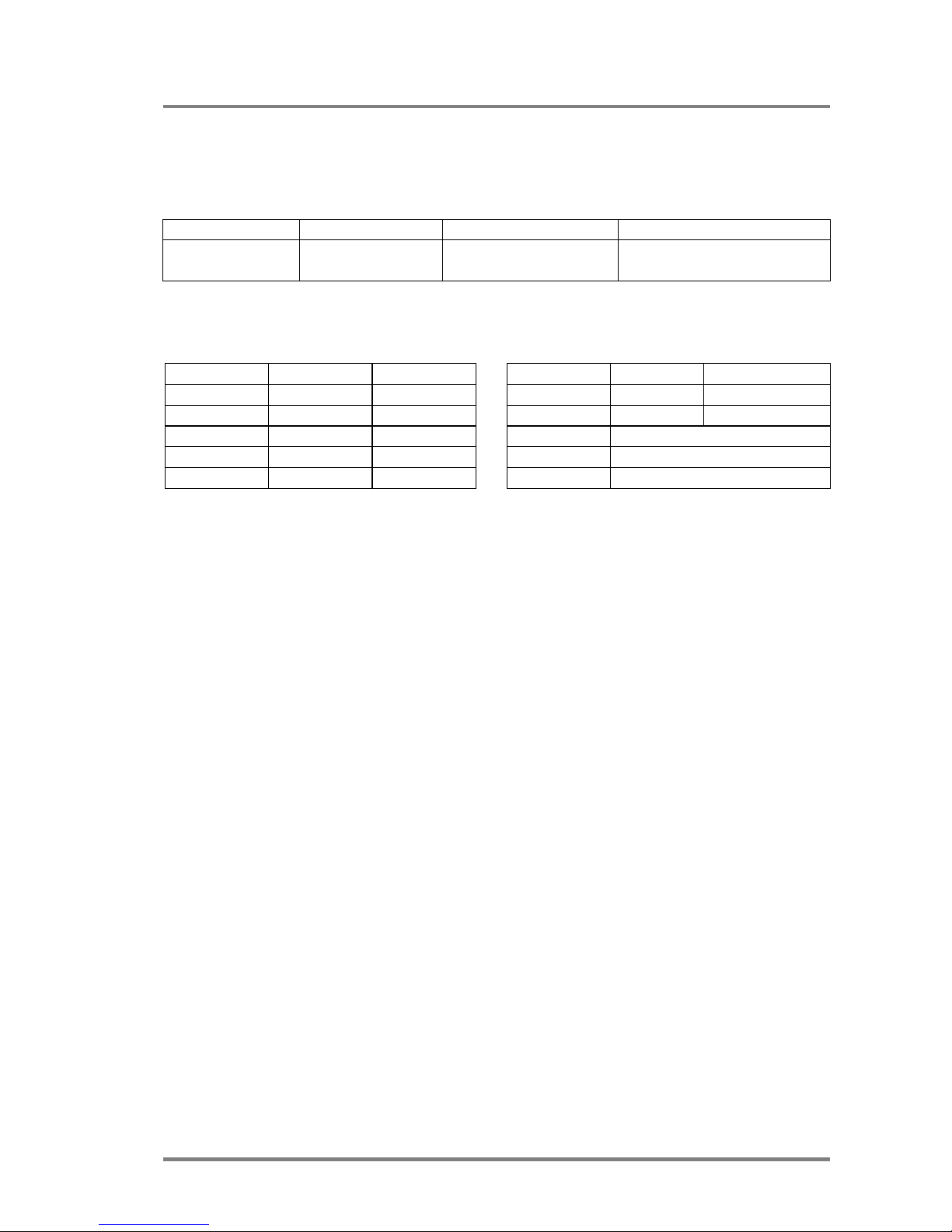
6. Production Quality
1. Hardware
Card HW BIOS Card HW BIOS
MX 4x4 DVI CD ROM
EDID Router LAN
Control P MAC ADDR
PSU IP ADDR
Subnet Mask
2. Final check
GND/EARTH
+3.3V & +5V
CPU Live
Buttons
EDID Router test
Inputs
Outputs
RS-232
LAN
Model name Serial number Date of manufacture Checked
 Loading...