

Lightware MX32x32HDMI-Pro, MX16x16HDMI-Pro, MX8x8HDMI-Pro, MX32x32DVI-HDCP-Pro, MX16x16DVI-HDCP-Pro User Manual
...Page 1
MX32x32HDMI-Pro
MX16x16HDMI-Pro
MX8x8HDMI-Pro
MX32x32DVI-HDCP-Pro
MX16x16DVI-HDCP-Pro
MX8x8DVI-HDCP-Pro
User's Manual
Page 2

Page 2 / 109
SAFETY INSTRUCTIONS
Class I apparatus construction. This equipment must be used with a main power
system with a protective earth connection. The third (earth) pin is a safety feature,
do not bypass, or disable it.
This equipment should be operated only from the power source indicated on the
product.
To disconnect the equipment safely from power, remove the power cord from the
rear of the equipment, or from the power source. The MAINS plug is used as the
disconnect device, the disconnect device shall remain readily operable.
There are no user-serviceable parts inside of the unit. Removal of the top cover will
expose dangerous voltages. To avoid personal injury, do not remove the top cover.
Do not operate the unit without the cover installed.
The apparatus shall not be exposed to dripping or splashing and that no objects
filled with liquids, such as vases, shall be placed on the apparatus.
The apparatus must be safely connected to multimedia systems. Follow
instructions described in this manual.
Rep lacin g the AC f use
Unplug the AC power cord from the equipment
Locate the AC fuse on the rear of the unit
Replace only the AC fuse as indicated on the rear panel of the unit:
Connect the power cord to the switcher and to the AC power source. Make sure
the switcher is working properly.
WEEE
(Wast e Ele c tric a l & E l ectro n ic Eq u ipmen t)
Corr e ct Di s posa l of T h is Pr o duct
This marking shown on the product or its literature, indicates that it should not be
disposed with other household wastes at the end of its working life. To prevent
possible harm to the environment or human health from uncontrolled waste disposal,
please separate this from other types of wastes and recycle it responsibly to promote
the sustainable reuse of material resources.
Household users should contact either the retailer where they purchased this product,
or their local government office, for details of where and how they can take this item
for environmentally safe recycling.
Business users should contact their supplier and check the terms and conditions of the purchase
contract. This product should not be mixed with other commercial wastes for disposal.
Page 3

MX32x32DVI-HDCP-Pro and HDMI-Pro
User’s Manual v1.0
Page 3/ 109
DECLARATION OF CONFORMITY
We,
Lightware Kft. 1071 Budapest Peterdy str. 15 HUNGARY
as manufacturer declares, that the products
MX32x32HDMI-Pro
MX16x16HDMI-Pro
MX8x8HDMI-Pro
MX32x32DVI-HDCP-Pro
MX16x16DVI-HDCP-Pro
MX8x8DVI-HDCP-Pro
( Video Matrix Switcher )
in accordance with the EMC Directive 2004/108/EC and the Low Voltage Directive
2006/95/EEC are in conformity with the following standards:
EMI/EMC .................... EN 55103-1 E3, EN 55103-2
Safety .......................................... EN 60065 Class I
Date: 01 September 2007
Name: Gergely Vida ( Managing Director )
Signed:
Page 4

Page 4 / 109
Table of contents
1. BOX CONTENTS............................................................................................................................ 7
2. MODULAR ROUTER CONCEPT ................................................................................................... 8
2.1. MX8X8
SERIES
......................................................................................................................... 8
2.1.1.
Front Panel view (all MX8x8 series) .............................................................................. 8
2.1.2.
Rear view (MX8x8DVI-HDCP-Pro) ................................................................................ 9
2.1.3.
Rear view (MX8x8HDMI-HDCP-Pro)............................................................................. 9
2.2. MX-DVI-FR16 ....................................................................................................................... 10
2.2.1.
Rear view of MX-DVI-FR16 ......................................................................................... 10
2.3. MX-DVI-FR32R .................................................................................................................... 10
2.4. CPU-CARD .......................................................................................................................... 11
2.5. I
NPUT CARDS
......................................................................................................................... 12
2.5.1.
MX-DVI-HDCP-IB ........................................................................................................ 12
2.5.2.
MX-HDMI-IB ................................................................................................................ 13
2.5.3.
MX-HDMI-TP-IB ........................................................................................................... 14
2.5.4.
MX-OPT-HDMI-IB ........................................................................................................ 15
2.6. O
UTPUT CARDS
...................................................................................................................... 16
2.6.1.
MX-DVI-HDCP-OB ...................................................................................................... 16
2.6.2.
MX-HDMI-OB ............................................................................................................... 17
2.6.3.
MX-HDMI-TP-OB ......................................................................................................... 18
2.6.4.
MX-OPT-HDMI-OB ...................................................................................................... 19
2.7. G
ENERAL FEATURES
............................................................................................................... 20
2.8. E
LECTRICAL CONNECTIONS
..................................................................................................... 22
2.8.1.
Signal inputs ................................................................................................................ 22
2.8.2.
BR-N Optional Neutrik breakout box ........................................................................... 24
2.8.3.
Maximal Cable length at inputs ................................................................................... 25
2.8.4.
Signal outputs .............................................................................................................. 26
2.8.5.
Power connection ........................................................................................................ 26
2.8.6.
RS-232/422 and Ethernet control port ......................................................................... 27
3. OPERATION ................................................................................................................................. 28
3.1. POWER ................................................................................................................................ 28
3.2. FRONT PANEL OPERATIONS ............................................................................................ 28
3.2.1.
TAKE / AUTOTAKE modes ......................................................................................... 28
3.2.2.
CONTROL LOCK ........................................................................................................ 28
3.2.3.
SWITCHING ................................................................................................................ 29
3.2.4.
SAVE or LOAD PRESETS .......................................................................................... 30
3.2.5.
VIEW crosspoint state ................................................................................................. 31
3.2.6.
VIEW live inputs and attached monitors ...................................................................... 31
3.2.7.
OUTPUT LOCK ........................................................................................................... 32
3.3. F
RONT PANEL
LCD M
ENU OPERATION
..................................................................................... 33
3.3.1.
Basic concept .............................................................................................................. 33
3.3.2.
Normal mode ............................................................................................................... 34
3.3.3.
EDID mode .................................................................................................................. 36
3.3.4.
Signal Present mode ................................................................................................... 37
4. PROGRAMMER’S REFERENCE................................................................................................. 38
4.1. S
WITCHING AND CONTROL COMMANDS
..................................................................................... 40
4.1.1.
Switch one input to one output .................................................................................... 40
4.1.2.
Switch one input to all outputs ..................................................................................... 40
4.1.3.
View connection on the specified output ..................................................................... 40
4.1.4.
View connection on all outputs .................................................................................... 40
4.1.5.
View mutes on all outputs ............................................................................................ 41
4.1.6.
Mute specified output .................................................................................................. 42
4.1.7.
Unmute specified output .............................................................................................. 42
4.1.8.
Lock specified output ................................................................................................... 42
4.1.9.
Unlock specified output ............................................................................................... 42
4.1.10. Save preset to the specified memory location ............................................................. 43
Page 5

MX32x32DVI-HDCP-Pro and HDMI-Pro
User’s Manual v1.0
Page 5/ 109
4.1.11. Load preset from the specified location ...................................................................... 43
4.1.12. View preset without loading ........................................................................................ 43
4.1.13. Name Presets / Inputs / Outputs ................................................................................. 43
4.1.14. Query names of Presets / Inputs / Outputs ................................................................. 44
4.1.15. Set default names of Presets / Inputs / Outputs ......................................................... 44
4.1.16. Query IP settings ......................................................................................................... 45
4.1.17. Reload factory default IP settings ............................................................................... 45
4.1.18. Load DHCP IP settings (only IP address!) .................................................................. 46
4.2. R
OUTER STATUS COMMANDS
................................................................................................. 46
4.2.1.
View product type ........................................................................................................ 46
4.2.2.
View serial number ...................................................................................................... 46
4.2.3.
View Firmware version of the CPU ............................................................................. 46
4.2.4.
View Router’s health ................................................................................................... 47
4.2.5.
View Installed I/O cards’ hardware .............................................................................. 47
4.2.6.
View installed controllers’ firmware ............................................................................. 48
4.2.7.
View current control protocol ....................................................................................... 48
4.2.8.
Set current control protocol ......................................................................................... 48
4.3. EDID
ROUTER COMMANDS
...................................................................................................... 49
4.3.1.
Route EDID to the selected input (static) .................................................................... 49
4.3.2.
Route EDID to the selected input (dynamic) ............................................................... 49
4.3.3.
Route one EDID to all inputs ....................................................................................... 49
4.3.4.
View EDID switch status on all inputs ......................................................................... 49
4.3.5.
Save EDID from output to memory location (Learn EDID) ......................................... 50
4.3.6.
View EDID validity table .............................................................................................. 50
4.3.7.
View EDID header ....................................................................................................... 50
4.3.8.
Upload EDID content from the router .......................................................................... 52
4.3.9.
Download EDID content to the router ......................................................................... 52
4.4. R
OUTER INITIATED COMMANDS
................................................................................................ 53
4.4.1.
EDID status changed .................................................................................................. 53
4.4.2.
Port Status Changed** ................................................................................................. 53
4.4.3.
Router ready (after power up or restart) ...................................................................... 53
4.4.4.
Error responses ........................................................................................................... 54
4.5. I
NPUT AND OUTPUT PORT STATUS
............................................................................................ 55
4.5.1.
Check the status of the inputs ..................................................................................... 55
4.5.2.
Check the status of the outputs ................................................................................... 55
4.5.3.
Setting the cable equalization ..................................................................................... 56
4.5.4.
Get the actual cable equalization value on an input port ............................................ 56
4.5.5.
Get detailed information about a HDMI input port ....................................................... 56
4.5.6.
Get detailed information about a HDMI output port .................................................... 62
4.5.7.
Set color range conversion at a HDMI input port ........................................................ 64
4.5.8.
Set HDMI output port parameters ............................................................................... 64
4.5.9.
Reset HDCP cache .................................................................................................... 66
4.5.10. Measure timing parameters......................................................................................... 66
5. SOFTWARE CONTROL –USING LIGHTWARE MATRIX CONTROLLER ................................ 68
5.1. E
STABLISHING THE CONNECTION
............................................................................................. 68
5.2. C
ONTROL MENU
..................................................................................................................... 69
5.2.1.
Switch, mute and lock ................................................................................................. 69
5.2.2.
Input and output states ................................................................................................ 70
5.2.3.
Card types ................................................................................................................... 70
5.2.4.
PRESET operations .................................................................................................... 71
5.3. EDID
MENU
........................................................................................................................... 72
5.3.1.
EDID Router operation ................................................................................................ 72
5.3.2.
Advanced EDID Manager............................................................................................ 74
5.4. T
ERMINAL MENU
..................................................................................................................... 74
5.5. STATUS
MENU
...................................................................................................................... 74
5.5.1.
IP configuration ........................................................................................................... 75
5.6. F
IND MENU
............................................................................................................................. 77
5.7. I
NPUT AND OUTPUT SETTINGS
................................................................................................. 77
5.7.1.
Set HDMI parameters on input .................................................................................... 77
Page 6

Page 6 / 109
5.7.2.
Set HDMI parameters on output .................................................................................. 79
6. USING THE WEB INTERFACE ................................................................................................... 82
6.1. A
CCESSING THE ROUTER’S WEB PAGE
..................................................................................... 82
6.2. M
ANAGE CROSSPOINTS AND PRESETS
..................................................................................... 82
6.3. HDMI
SETTINGS
..................................................................................................................... 83
6.4. EDID R
OUTER OPERATION
...................................................................................................... 85
6.4.1.
Change emulated EDID at one or all inputs ................................................................ 85
6.4.2.
Learn EDID from attached display device ................................................................... 86
6.5. S
TATUS
.................................................................................................................................. 86
6.6. N
ETWORK CONFIGURATION
..................................................................................................... 87
6.6.1.
Assign IP address automatically .................................................................................. 87
6.6.2.
Static IP address configuration .................................................................................... 88
6.6.3.
Loading the default IP settings .................................................................................... 88
6.6.4.
TCP Port Configuration ............................................................................................... 88
6.6.5.
Loading the default TCP Port settings ......................................................................... 89
6.7. S
UPPORT
............................................................................................................................... 89
7. ADVANCED EDID MANAGEMENT ............................................................................................. 90
7.1. W
HY IS
EDID
MANAGEMENT NECESSARY
? ............................................................................... 90
7.2. A
BOUT ADVANCED
EDID M
ANAGEMENT
.................................................................................. 91
7.3. A
BOUT THE ADVANCED
EDID M
ANAGER
.................................................................................. 92
8. FIRMWARE UPGRADE ............................................................................................................... 93
9. TROUBLESHOOTING ................................................................................................................. 97
9.1. S
ERIAL CONNECTION PROBLEMS
.............................................................................................. 97
9.2. TCP/IP
CONNECTION PROBLEMS
............................................................................................. 97
9.3. T
HERE IS NO PICTURE
............................................................................................................. 97
9.4. T
HERE IS NO INPUT SIGNAL
...................................................................................................... 98
9.5. T
HERE IS NO SOUND
............................................................................................................... 99
10.
MECHANICAL DRAWINGS .................................................................................................. 100
10.1. F
RONT VIEW
......................................................................................................................... 100
10.2. R
EAR VIEW
........................................................................................................................... 101
10.3. T
OP VIEW
............................................................................................................................. 102
10.4. L
EFT VIEW
............................................................................................................................ 104
10.5. R
IGHT VIEW
.......................................................................................................................... 105
11.
WARRANTY ........................................................................................................................... 106
12.
QUALITY CHECK RECORD ................................................................................................. 107
12.1. H
ARDWARE
.......................................................................................................................... 107
12.2. E
LECTRICAL CHECK
.............................................................................................................. 107
Page 7

MX32x32DVI-HDCP-Pro and HDMI-Pro
User’s Manual v1.0
Page 7/ 109
1. Box contents
Routing switcher
Rack mounting ears
User's manual
IEC power cable
CD-ROM with control software
RS-232 9-pole D-sub Male to Female cable
UTP cross-link cable
Page 8
Page 8 / 109
2. Modular router concept
MX8x8HDMI-Pro and MX8x8DVI-HDCP-Pro are fixed I/O size matrix switchers
with eight inputs and eight outputs respectively.
MX32x32 series and MX16x16 series Pro routers are modular matrix switchers that
allow building custom I/O sizes that meet the user’s requirements. Different types
of input and output cards give the maximum flexibility for rental and installation
signal transmission.
2.1. MX8x8 series
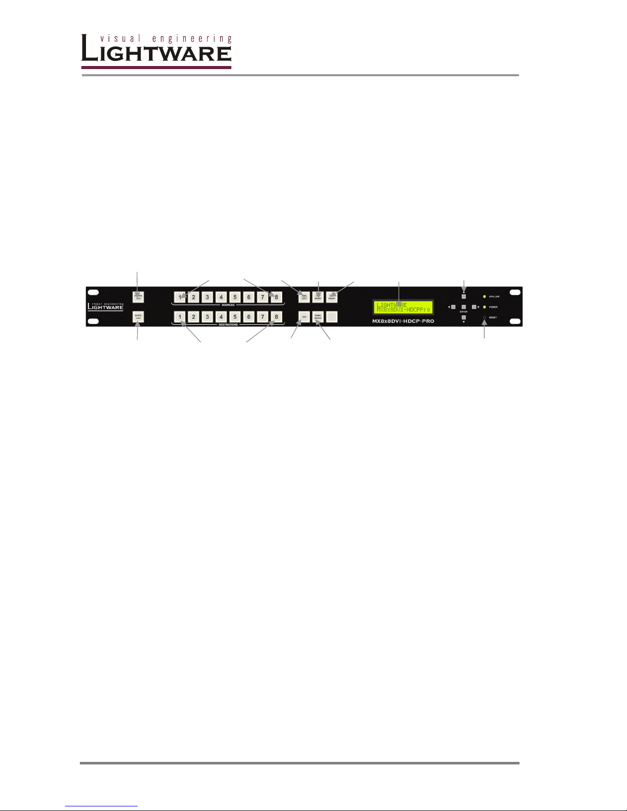
2.1.1. Front Panel view (all MX8x8 series)
CONTROL LOCK Sources Take/ Load Save Status Navigation
1 to 8 Autotake Preset Preset LCD buttons
OUTPUT Destinations EDID Signal Reset
LOCK 1 to 8 Present
Control Lock Disables or enables front panel operation. When it
illuminates red, operations on front panel are prohibited.
Output Lock Locks and protects one (or more) outputs. It inhibits
accidental input changing on protected outputs.
Sources Source buttons have three functions: to select an input,
to select a preset number and to view the selected input’s
state (take mode).
Destinations Destination buttons have two functions: to select an
output, or to view the selected output’s state.
Take/Autotake This button has two functions: displays the actual
switching mode of the router (TAKE mode or AUTOTAKE
mode) or executes switching in TAKE mode.
Load Preset Loads and executes a previously saved preset from one
of the preset memories.
Save Preset Stores actual matrix state in one of preset memories.
EDID Switches the LCD to EDID menu allowing EDID switch,
EDID save etc.
Signal Present Displays live sources and attached sinks on source and
destination buttons.
Status LCD 2x16-character LCD display for menu operations.
Navigation buttons (UP, DOWN, LEFT, RIGHT, ENTER) buttons for menu
navigation.
Reset Hardware reset button. It resets the whole router,
however saved settings, presets and EDIDs will be
preserved.
Power LED Green LED indicating that the unit is powered on.
CPU LIVE LED Green blinking LED indicating normal operation.
Page 9
MX32x32DVI-HDCP-Pro and HDMI-Pro
User’s Manual v1.0
Page 9/ 109
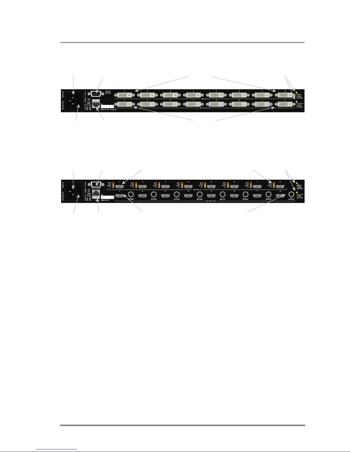
2.1.2. Rear view (MX8x8DVI-HDCP-Pro)
AC Power RS-232 DVI-D Inputs Card activity
connector port 1-8 LEDs
Fuse Ethernet port DVI-D Outputs
1-8
2.1.3. Rear view (MX8x8HDMI-HDCP-Pro)
AC Power RS-232 Card activity
connector port HDMI Inputs Input status LEDs LEDs
Fuse Ethernet HDMI Outputs S/PDIF Outputs
port
AC Power Standard IEC power connector. The router works with
100 to 240 Volts, 50 or 60 Hz power sources.
AC Fuse Replace with F 3.15A type only.
RS-232/422 connector 9-pole D-sub female connector. Can be ordered with RS-
232 or RS-422 control.
Ethernet port Standard RJ45 connector. This port can be connected to
Local Area Network.
DVI-D inputs Standard 29-pole DVI connectors for input connections. It
accepts only digital signals.
DVI-D outputs Standard 29-pole DVI connectors for outputs.
HDMI inputs 19-pole type A HDMI connectors for input connections.
HDMI outputs 19-pole type A HDMI connectors for output connections.
S/PDIF outputs RCA jack connector with S/PDIF digital audio signal.
Embedded audio is still present on HDMI outputs.
Input status LEDs Four LEDs help the signal monitoring on each HDMI
input port. They indicate the presence of power +5V, the
presence of an active video signal, HDMI mode and the
HDCP encryption status.
Card activity LEDs These LEDs are blinking when the cards are active.
Page 10
Page 10 / 109
2.2. MX-DVI-FR16
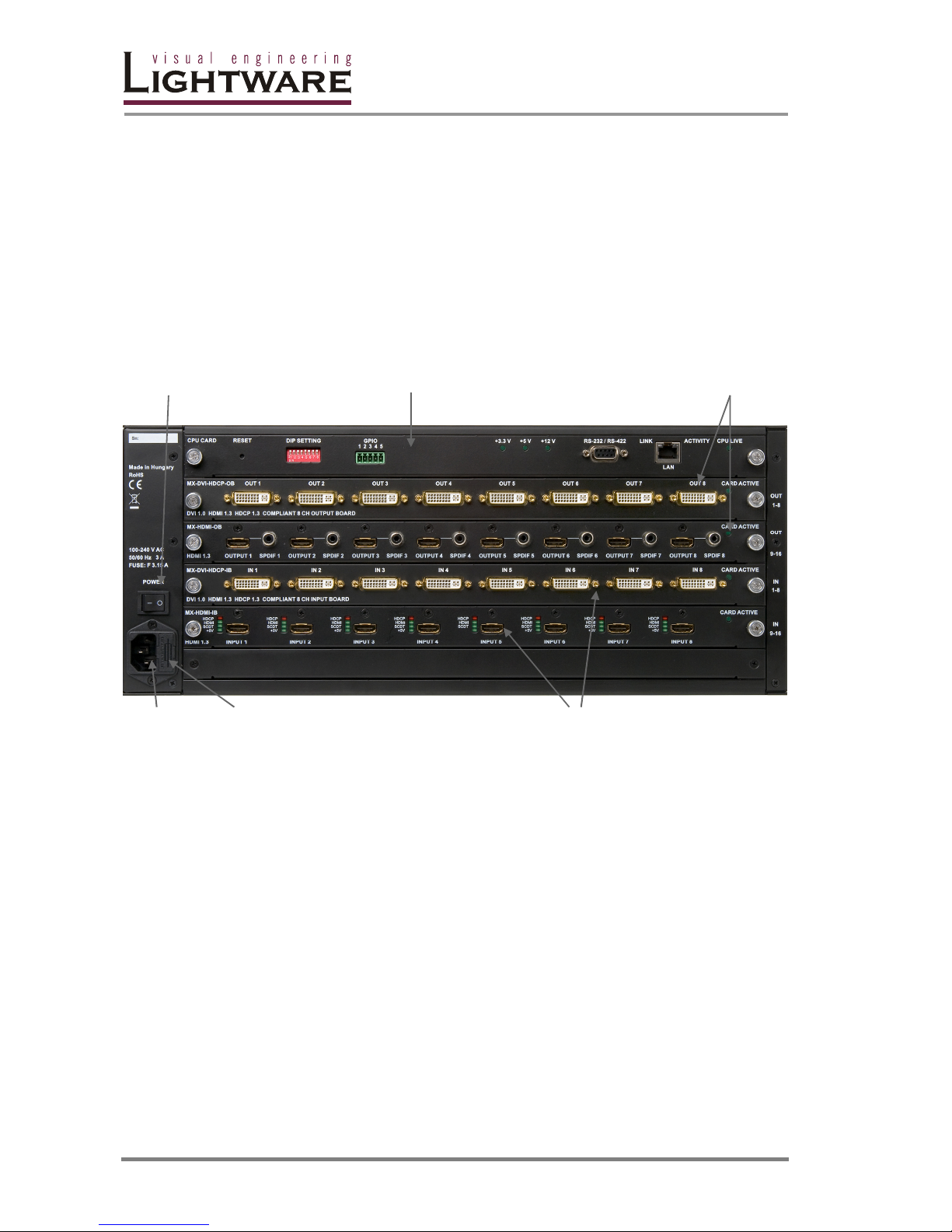
The MX-DVI-FR16 modular frame allows building custom matrices with up to 16
inputs and 16 outputs. The card in the uppermost slot must be a CPU card that is
responsible for controlling the matrix. The two input and two output slots accept
any kind of input and output card which are described in section 2.5 and section
2.6.
The front panel has exactly the same controls as the MX8x8 series but with 16
input and 16 output selector buttons.
2.2.1. Rear view of MX-DVI-FR16
Power switch CPU Card Output cards (1..2)
AC Power AC Fuse Input cards (1..2)
connector (F 3.15A only)
2.3. MX-DVI-FR32R
The MX-DVI-FR32 modular frame allows building custom matrices with up to 32
inputs and 32 outputs. The card in the uppermost slot must be a CPU card that is
responsible for controlling the matrix. The two input and two output slots accept
any kind of input and output card which are described in section 2.5 and section
2.6.
The front panel has exactly the same controls as the MX8x8 series but with 32
input and 32 output selector buttons.
This frame can be ordered with redundant power supply.
Page 11

MX32x32DVI-HDCP-Pro and HDMI-Pro
User’s Manual v1.0
Page 11/ 109
2.4. CPU-CARD
Reset DIP GPIO contact DC voltage RS-232/422 Ethernet CPU LIVE
button switch closure indicators port port LED
In order for the MX-DVI-FR16(R) and MX-DVI-FR32R frames to work, a CPUCARD is needed. This card is responsible for controlling the matrix and storing all
the settings.
Reset button Hardware reset button. Press to reset the whole frame.
Crosspoints and presets will not be reset.
DIP Switch 8-circuit DIP switch – not used in current version.
GPIO Contact closure Relay output for alarm signaling.
DC voltage indicators LED indicators for internal DC power voltages. All LEDs
must light continuously during normal operation.
RS 232/422 connector 9-pole D-sub female connector. Can be ordered with RS-
232 or RS-422 control.
Ethernet port RJ45 connector. Remote control port for connecting the
unit to Local Area Network.
CPU LIVE LED Green blinking LED indicating normal operation.
Page 12
Page 12 / 109
2.5. Input Cards
2.5.1. MX-DVI-HDCP-IB
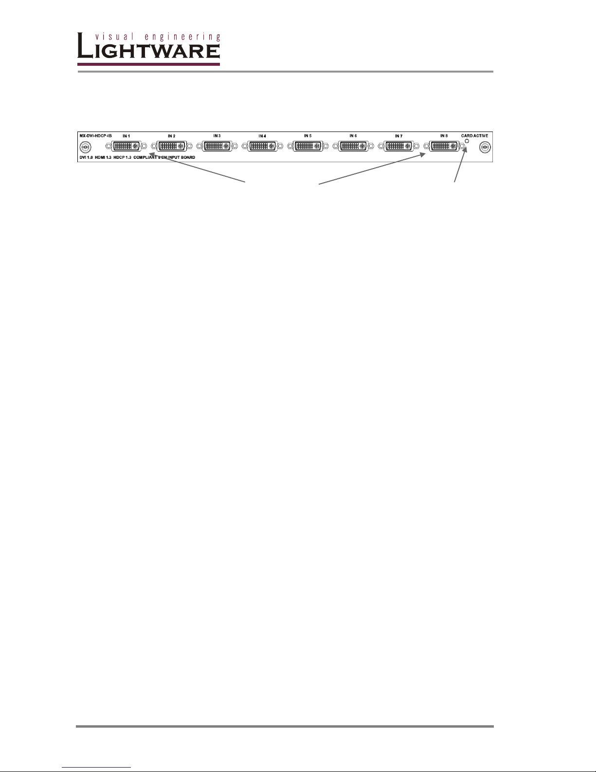
DVI connectors Card active LED
This 8-channel DVI-D (digital only) input card supports single link DVI signals up to
165MHz pixel clock and HDMI 1.3 signals including deep color modes and audio
signals. The built-in cable equalization enables the use of long cables as specified
on page 25.
Connectors 8 DVI-I (only digital pins are connected)
Cable equalization Automatic or manual, up to 40dB
Signal reclocking Yes
DVI support Up to 165MHz pixel clock, single link only
HDMI support HDMI 1.3 compliant
Up to 225MHz pixel clock
16, 24, 30 and 36 bits/pixel are supported
RGB, YUV 4:4:4 and YUV 4:2:2 modes
Audio PCM (up to 192 kHz and 8 channels), Dolby, DTS, MLP,
Dolby True-HD and DTS-HD Master Audio support
HDCP HDCP 1.3 compliant
Signal monitoring PWR5V, SCDT
HDMI/DVI mode discrimination
HDCP encryption status
Resolution, Vsync and Hsync frequencies
Color space
Audio information (type, sampling frequency, channels)
Timing parameters (front porch, back porch, pixel
repetition, TMDS and pixel clock frequency and so on)
Processing Color range compression or expansion
EDID emulation 256-byte E-EDID
Page 13
MX32x32DVI-HDCP-Pro and HDMI-Pro
User’s Manual v1.0
Page 13/ 109
2.5.2. MX-HDMI-IB
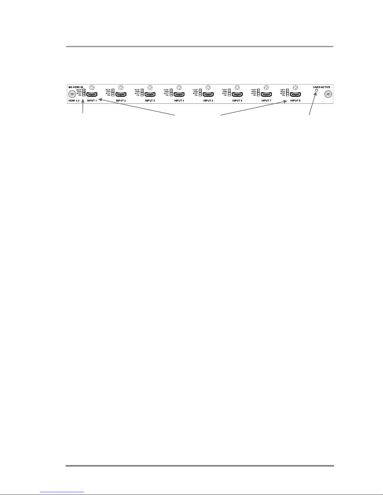
Status LEDs HDMI connectors Card active LED
This 8-channel HDMI input card has exactly the same capabilities as the
MX-DVI-HDCP-IB described above in section 2.5.1. It is built with 19-pole type A
HDMI connectors and each input has four status LEDs to help the installation and
debugging process. These LEDs indicate the following (from bottom to top):
+5V Source is connected and powered. The PWR5V pin is
driven by source with an active high signal.
SCDT Valid video signal is detected and sync can be extracted.
HDMI If this LED illuminates, the incoming signal is HDMI. If it
does not illuminate then the incoming signal is DVI.
HDCP It illuminates red when the incoming signal is content
protected and HDCP encrypted.
Info: During the booting process the state of these LEDs is undetermined.
Connectors 8 HDMI Type A connectors
Cable equalization Automatic or manual, up to 40dB
Signal reclocking Yes
DVI support Up to 165MHz pixel clock, single link only
HDMI support HDMI 1.3 compliant
Up to 225MHz pixel clock
16, 24, 30 and 36 bits/pixel are supported
RGB, YUV 4:4:4 and YUV 4:2:2 modes
Audio PCM (up to 192 kHz and 8 channels), Dolby, DTS, MLP,
Dolby True-HD and DTS-HD Master Audio support
HDCP HDCP 1.3 compliant
Signal monitoring PWR5V, SCDT
HDMI/DVI mode discrimination
HDCP encryption status
Resolution, Vsync and Hsync frequencies
Color space
Audio information (type, sampling frequency, channels)
Timing parameters (front porch, back porch, pixel
repetition, TMDS and pixel clock frequency and so on)
Processing Color range compression or expansion
EDID emulation 256-byte E-EDID
Page 14
Page 14 / 109
2.5.3. MX-HDMI-TP-IB
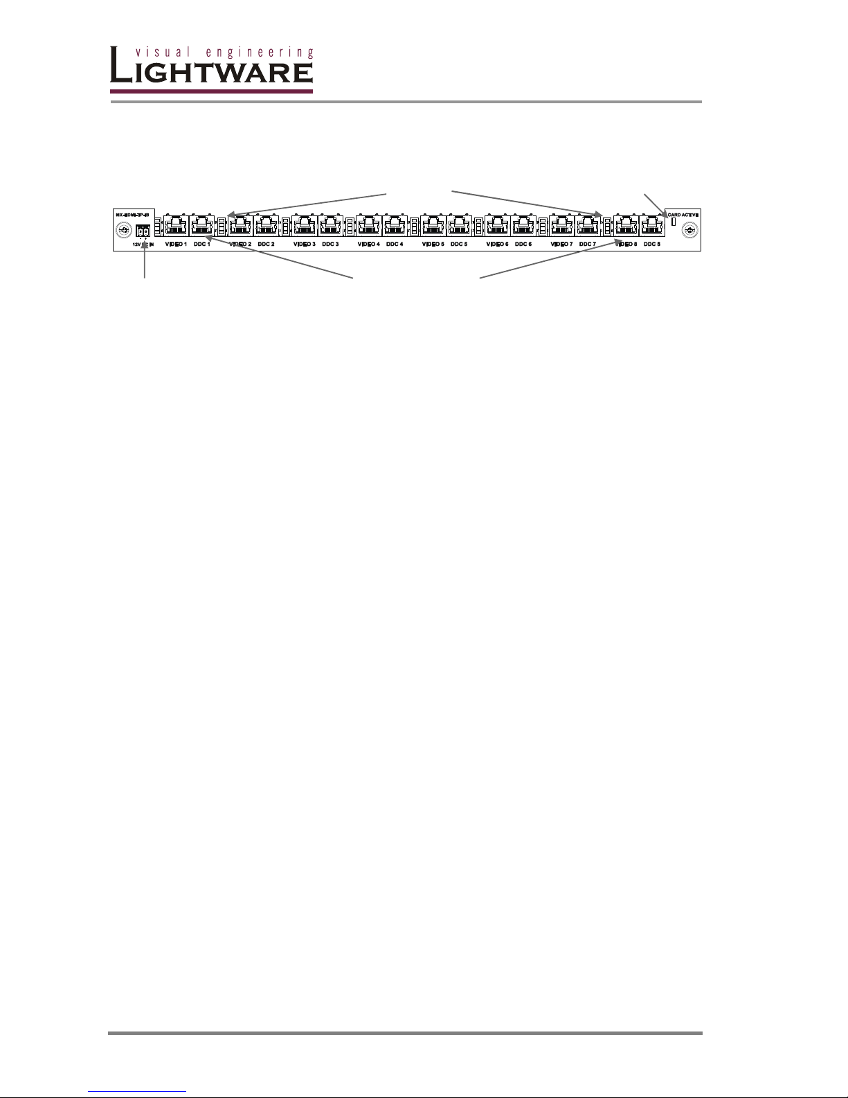
Status LEDs Card active LED
12V DC power RJ45 connectors (Video and DDC)
This 8-channel HDMI input card is equipped with two RJ45 connectors per each
input. The card has exactly the same capabilities as the MX-DVI-HDCP-IB
described above in section 2.5.1. There are three status LEDs next to every input,
which indicate the following (from bottom to top):
SCDT Valid video signal is detected and sync can be extracted.
HDMI If this LED illuminates, the incoming signal is HDMI. If it
does not illuminate then the incoming signal is DVI.
HDCP It illuminates red when the incoming signal is content
protected and HDCP encrypted.
During the booting process the state of these LEDs is undetermined.
Connectors 8 HDMI Type A connectors
Signal reclocking Yes
DVI support Up to 165MHz pixel clock, single link only
HDMI support HDMI 1.3 compliant
Up to 225MHz pixel clock
16, 24, 30 and 36 bits/pixel are supported
RGB, YUV 4:4:4 and YUV 4:2:2 modes
Audio PCM (up to 192 kHz and 8 channels), Dolby, DTS, MLP,
Dolby True-HD and DTS-HD Master Audio support
HDCP HDCP 1.3 compliant
Signal monitoring The same as described above in section 2.5.1
Processing Color range compression or expansion
EDID emulation 256-byte E-EDID
The pin assignment for the RJ45 connectors can be found on page 23. The
maximum cable lengths are specified on page 25.
This card is compatible with the following Lightware products:
DVI-HDCP-TP-TX100
HDMI-HDCP-TP-TX100
MX-HDMI-TP-OB (see 2.6.3.)
DVI-TP-TX200 (DVI signals only, HDCP is not supported)
MX-DVI-TP-OB card (DVI signals only, HDCP is not supported)
For further details on these devices, please visit the http://www.lightware.eu
webpage.
Page 15
MX32x32DVI-HDCP-Pro and HDMI-Pro
User’s Manual v1.0
Page 15/ 109
2.5.4. MX-OPT-HDMI-IB
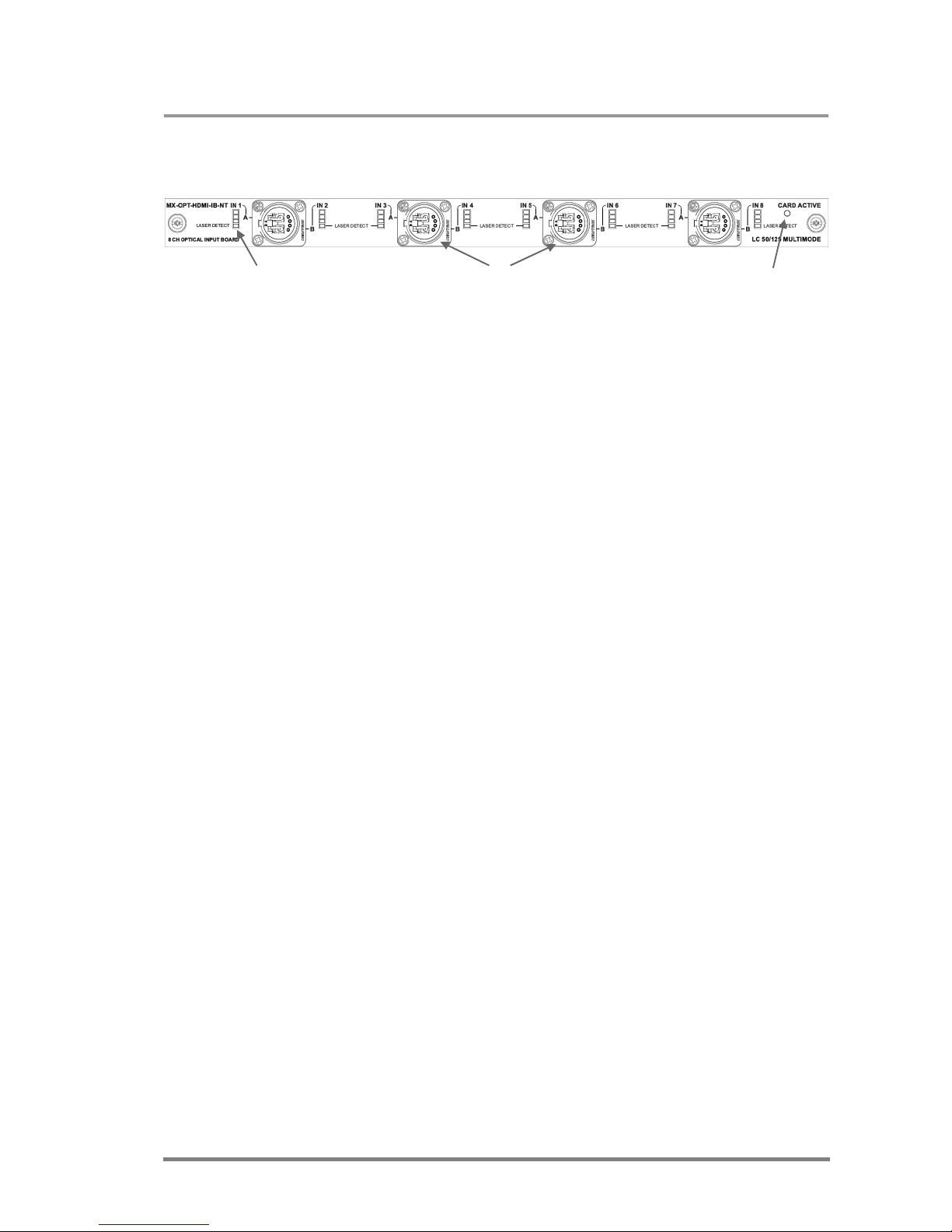
Status LEDs Optical connectors Card active LED
(can be ordered with with NT, LC, ST or SC connectors)
This 8-channel optical input card is fully compatible with the HDMI 1.3 and HDCP
1.3 standard. This card uses Lightware’s Single Fiber Technology, which
eliminates the need for additional copper cables. Only one multimode fiber cable is
used per one DVI signal. Single fiber technology lowers the system infrastructure
cost and isolates sources and receivers from ground loops and hum noises.
Main features:
Connectors 8x LC or 8x SC or 8x ST or 8x Neutrik NO2-4FD type
Max. cable length 2600 meters at 1080p
Cable type 50/125 multimode fiber
HDMI HDMI 1.3 compliant
Up to 225MHz pixel clock
16, 24, 30 and 36 bits/pixel are supported
RGB, YUV 4:4:4 and YUV 4:2:2 modes
Audio PCM (up to 192kHz and 8 channel), Dolby, DTS, MLP,
Dolby True-HD and DTS-HD Master Audio support
HDCP HDCP 1.3 compliant
There are four status LEDs next to every input, which indicate the following (from
bottom to top):
LASER detect It illuminates green when laser beam is detected.
SCDT It illuminates green when pixel clock is detected.
HDMI If this LED illuminates, the incoming signal is HDMI. If it
does not illuminate then the incoming signal is DVI.
HDCP It illuminates red when the incoming signal is content
protected and HDCP encrypted.
This card is compatible with the following Lightware products:
HDMI-OPT-TX300
MX-HDMI-OPT-OB (see 2.6.4.)
DVI-OPT-TX100 (DVI signals only, HDCP is not supported)
DVI-OPT-TX200 (DVI signals only, HDCP is not supported)
MX-DVI-OPT-OB-NT card (DVI signals only, HDCP is not supported)
MX-DVI-OPT-OB-R-LC card (DVI signals only, HDCP is not supported)
For further details on these devices, please visit the http://www.lightware.eu
webpage.
Page 16
Page 16 / 109
2.6. Output Cards
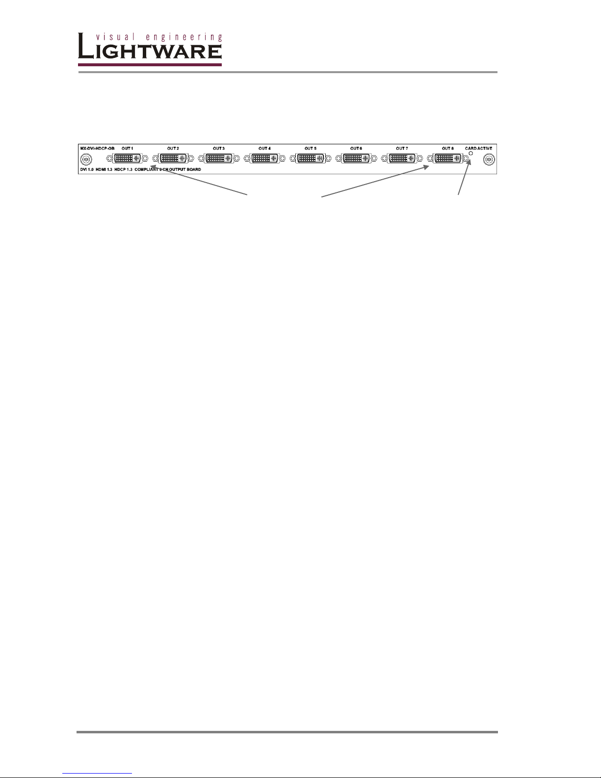
2.6.1. MX-DVI-HDCP-OB
DVI connectors Card active LED
8-channel DVI-D (digital only) output card. It is compatible with HDMI1.3 and
HDCP standards and allows making specific conversions independently on each
output port. These conversions can be done automatically based on the EDID of
the display or can be manipulated manually.
Connectors 8 DVI-I (only digital pins are connected)
Signal reclocking Yes
DVI support Up to 165MHz pixel clock, single link only
HDMI support Up to 225MHz pixel clock, HDMI 1.3 compatible
Audio PCM (up to 192 kHz and 8 channels), Dolby, DTS, MLP,
Dolby True-HD and DTS-HD Master Audio support
HDCP HDCP 1.3 compliant
Signal monitoring Same as described at MX-DVI-HDCP-IB.
Processing HDMI-to-DVI, DVI-to-HDMI,
conversions between 24/30/36 bpp modes,
any-to-any color space converter,
color range compression or expansion,
downsampling 2ch PCM audio by 2x or 4x.
Page 17

MX32x32DVI-HDCP-Pro and HDMI-Pro
User’s Manual v1.0
Page 17/ 109
2.6.2. MX-HDMI-OB
HDMI outputs S/PDIF outputs Card active LED
8-channel HDMI 1.3 compatible output card. Each output port has an RCA
connector on which S/PDIF audio is sent, however the audio signal can be
transmitted on the HDMI ports at the same time.
Connectors 8x 19-pole type A HDMI connectors
8x RCA connectors
Signal reclocking Yes
DVI support Up to 165MHz pixel clock, single link only
HDMI support Up to 225MHz pixel clock, HDMI 1.3 compatible
HDCP HDCP 1.3 compliant
Signal monitoring Same as described at MX-DVI-HDCP-IB.
Conversions Same as described at MX-DVI-HDCP-OB.
Info: The Dolby True-HD and DTS-HD Master Audio formats cannot be outputted on the
RCA connectors due to their bandwidth needs, which exceed the maximum of the
S/PDIF standard.
Page 18
Page 18 / 109
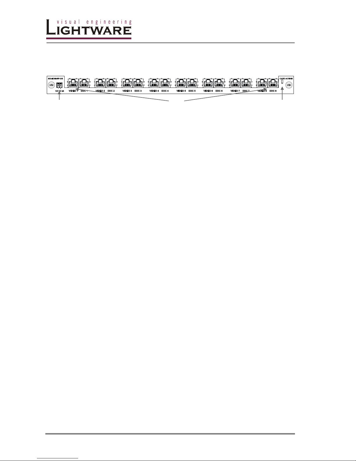
2.6.3. MX-HDMI-TP-OB
12V DC power RJ45 connectors (Video and DDC) Card active LED
This 8-channel HDMI 1.3 compatible output card is equipped with two RJ45
connectors per each port.
Connectors 8x 2 RJ45 connectors
Signal reclocking Yes
DVI support Up to 165MHz pixel clock, single link only
HDMI support Up to 225MHz pixel clock, HDMI 1.3 compatible
HDCP HDCP 1.3 compliant
Signal monitoring Same as described at MX-DVI-HDCP-IB.
Conversions Same as described at MX-DVI-HDCP-OB.
RS-232 This card can be ordered with an optional RS-232 add-on
card. Each port has an RS-232 connection, where the RX
and TX lines are connected to the RJ45 connectors.
S/PDIF It is possible to transmit the audio signal from the S/PDIF
connector instead of the RS-232 signal over the cable. It
is also possible to transmit the audio signal extracted
from the incoming HDMI signal. These settings can be
done by setting a jumper on the card.
This card is compatible with the following Lightware products:
DVI-HDCP-TP-RX100
HDMI-HDCP-TP-RX100
MX-HDMI-TP-IB (see 2.5.3)
DVI-TP-RX100 (DVI signals only, HDCP is not supported)
MX-DVI-TP-IB card (DVI signals only, HDCP is not supported)
For further details on these devices, please visit the http://www.lightware.eu
webpage.
Page 19
MX32x32DVI-HDCP-Pro and HDMI-Pro
User’s Manual v1.0
Page 19/ 109
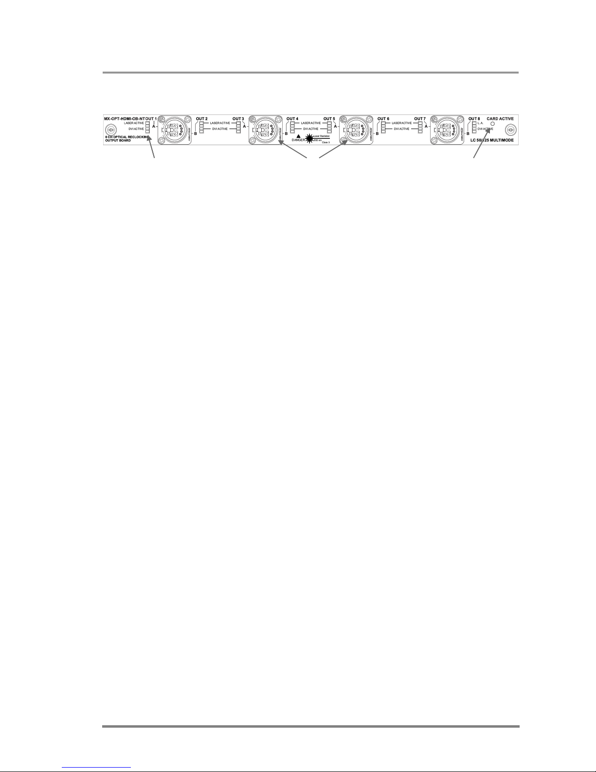
2.6.4. MX-OPT-HDMI-OB
Status LEDs Optical connectors Card active LED
(Can be ordered with NT, LC, ST or SC connectors)
This 8-channel optical output card is fully compatible with the HDMI 1.3 and HDCP
1.3 standards. This card uses Lightware’s Single Fiber Technology, which
eliminates the need for additional copper cables.
Main features:
Connectors 8x LC or 8x SC or 8x ST or 8x Neutrik NO2-4FD type
Cable type 50/125 multimode fiber
HDMI HDMI 1.3 compliant
Up to 225MHz pixel clock
16, 24, 30 and 36 bits/pixel are supported
RGB, YUV 4:4:4 and YUV 4:2:2 modes
PCM (up to 192kHz and 8 channels), Dolby, DTS, MLP,
Dolby True-HD and DTS-HD Master Audio support
HDCP HDCP 1.3 compliant
There are four status LEDs next to every input, which indicate the following (from
bottom to top):
LED0 Reserved
HDMI It illuminates green when the port operates in HDMI
mode
HDCP It illuminates green when HDCP encryption is active.
LASER active It illuminates red when laser beam is detected.
This card is compatible with the following Lightware products:
HDMI-OPT-RX300
MX-HDMI-OPT-IB (see 1.1.1.)
DVI-OPT-RX100 (DVI signals only, HDCP is not supported)
DVI-OPT-RX200 (DVI signals only, HDCP is not supported)
MX-DVI-OPT-IB-NT card (DVI signals only, HDCP is not supported)
MX-DVI-OPT-IB-R-LC card (DVI signals only, HDCP is not supported)
Page 20

Page 20 / 109
2.7. General features
Advanced EDID Management – The user can emulate any EDID on the
switcher's inputs independently, read out and store any
attached monitor's EDID in 100 internal memory
locations, upload and download EDID files using Matrix
Control Software.
Non-blocking cross point matrix architecture – The router allows any input to
be switched to any output or more outputs
simultaneously.
2.25 Gb/s channel transmission – Routes any DVI single link signal between 25
and 225 MHz pixel clock frequency conforming to DVI 1.0
and HDMI1.3 standards.
Supports all HDTV resolutions – 720p, 1080i, 1080p 2K etc. HDTV signals up to
225 MHz pixel clock frequency regardless of the actual
resolution passed through the router.
Control by front panel buttons – 32/16/8 source select, 32/16/8 destination
select, Take, Load preset, Save preset, Panel Lock,
Output Lock.
Relegendable buttons – Each button has an easy removable flat cap and a
translucent label that can be inserted under the cap to
identify sources and destinations.
RS-232 or RS-422 control – Simple ASCII based RS-232 protocol is used for
switching, preset calling, status request, etc.
Ethernet control – TCP/IP Ethernet 10Base-T or 100Base-TX (Auto-
Sensing).
Built-in WEB site – Easy access from a WEB browser to control and
configure the switcher.
Universal power supply – The routers accept AC voltages from 100 to 240 Volts
with 50 or 60 Hz line frequency on standard IEC
connector.
Power failure memory – In case of power failure, the unit stores its latest
configuration, and after next power up it loads
automatically.
HDCP compliant – All DVI-HDCP and HDMI routers comply with HDCP1.2
standard. Lightware is a legal HDCP adopter. The
included advanced HDCP management eliminates the
need for reauthentication upon switching.
50 meter input cable compensation – Using 22AWG high quality DVI or HDMI
cable, the inputs are automatically compensated for up to
50-meter cable length at 24bpp, which extends
installation possibilities even at the highest HDTV or
computer resolutions.
Input and Output PLL reclocking – (removes jitter caused by long cables) Each
output has a clean, jitter free signal, eliminating signal
instability and distortion caused by long cables or
connector reflections.
Signal analysis – Using the built-in webpage or Matrix Controller software
the user can monitor incoming signal parameters such as
resolution, signal timing parameters, color space, audio
Page 21

MX32x32DVI-HDCP-Pro and HDMI-Pro
User’s Manual v1.0
Page 21/ 109
type, scan rate, HDCP encryption and so on. (on specific
cards)
Color space and color range conversion – Video signals can be converted
between RGB, YUV 4:4:4 and YUV 4:2:2 signals in all
directions. Converting between limited and full range is
also possible. (on specific output cards)
Deep Color support and conversion – It is possible to transmit the highest
quality 30-bit or 36-bit video streams for perfect color
reproduction. The signal can be converted freely on each
output so you can get the best possible quality on every
display.
DVI/HDMI conversion – The router is able to convert between DVI and HDMI
signals so that you can watch HDMI videos on your
computer display without audio.
Page 22
Page 22 / 109
2.8. Electrical connections
2.8.1. Signal inputs
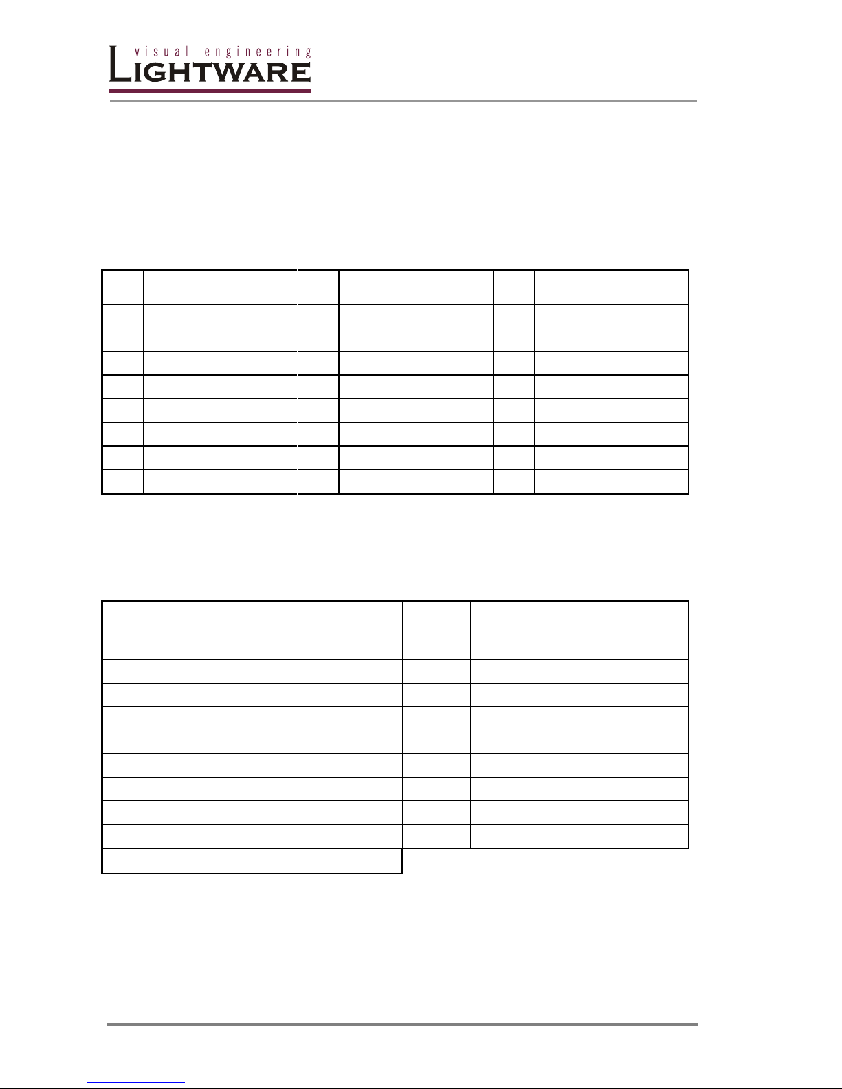
MX32x32DVI-HDCP-Pro, MX16x16DVI-HDCP-Pro and MX8x8DVI-HDCP-Pro
provide 29-pole DVI connectors for input connections, however only digital signal
pins are connected. Always use high quality DVI cables to connect sources and
displays.
Pin Signal Pin Signal Pin Signal
1
TMDS Data2-
9
TMDS Data1-
17
TMDS Data0-
2
TMDS Data2+
10
TMDS Data1+
18
TMDS Data0+
3
TMDS Data2 Shield
11
TMDS Data1 Shield
19
TMDS Data0 Shield
4
nc
12
nc
20
nc
5
nc
13
nc
21
nc
6
DDC Clock
14
+5V Power
22
TMDS Clock Shield
7
DDC Data
15
GND (for +5V)
23
TMDS Clock+
8
nc
16
Hot Plug Detect
24
TMDS Clock-
DVI connector Single Link pin assignment
MX32x32HDMI-Pro, MX16x16HDMI-Pro, and MX8x8HDMI-Pro provide 19-pole
type A HDMI connectors for input connections.
Pin Signal Pin Signal
1
TMDS Data2+
2
GND
3
TMDS Data2-
4
TMDS Data1+
5
GND
6
TMDS Data1-
7
TMDS Data0+
8
GND
9
TMDS Data0+
10
TMDS Clock+
11
GND
12
TMDS Clock-
13
nc
14
nc
15
SCL
16
SDA
17
DDC/CEC GND
18
+5V Power
19
Hot Plug Detect
HDMI connector pin assignment
Page 23
MX32x32DVI-HDCP-Pro and HDMI-Pro
User’s Manual v1.0
Page 23/ 109
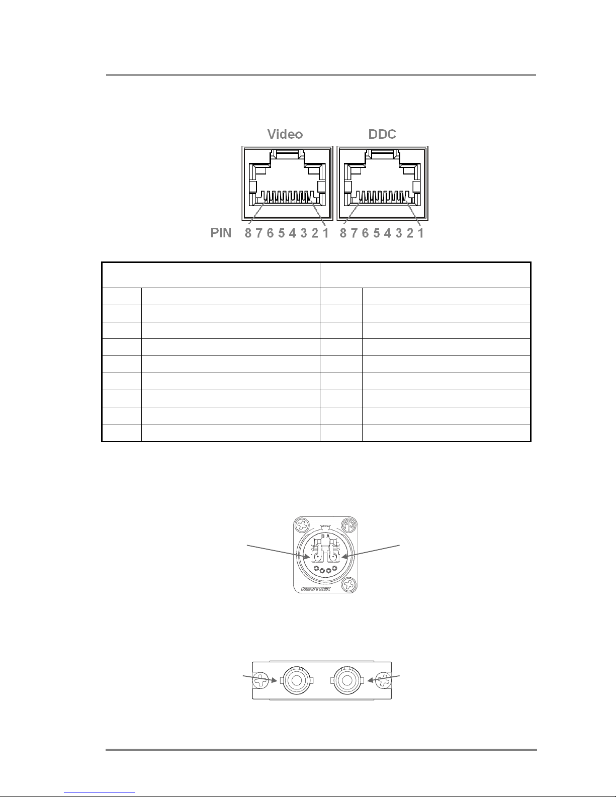
MX-HDMI-TP-IB and MX-HDMI-TP-OB cards use two RJ45 connectors per each
input.
Video (left connector) DDC (right connector)
Pin Signal Pin Signal
1
TMDS Data0+
1
nc
2
TMDS Data0-
2
Hot Plug Detect (out)
3
TMDS Clock+
3
RS232 TX (out)
4
TMDS Data1+
4
RS232 RX
5
TMDS Data1-
5
DDC SCL
6
TMDS Clock-
6
+12V (out)
7
TMDS Data2+
7
DDC SDA
8
TMDS Data2-
8
GND
RJ45 connector PIN assignment
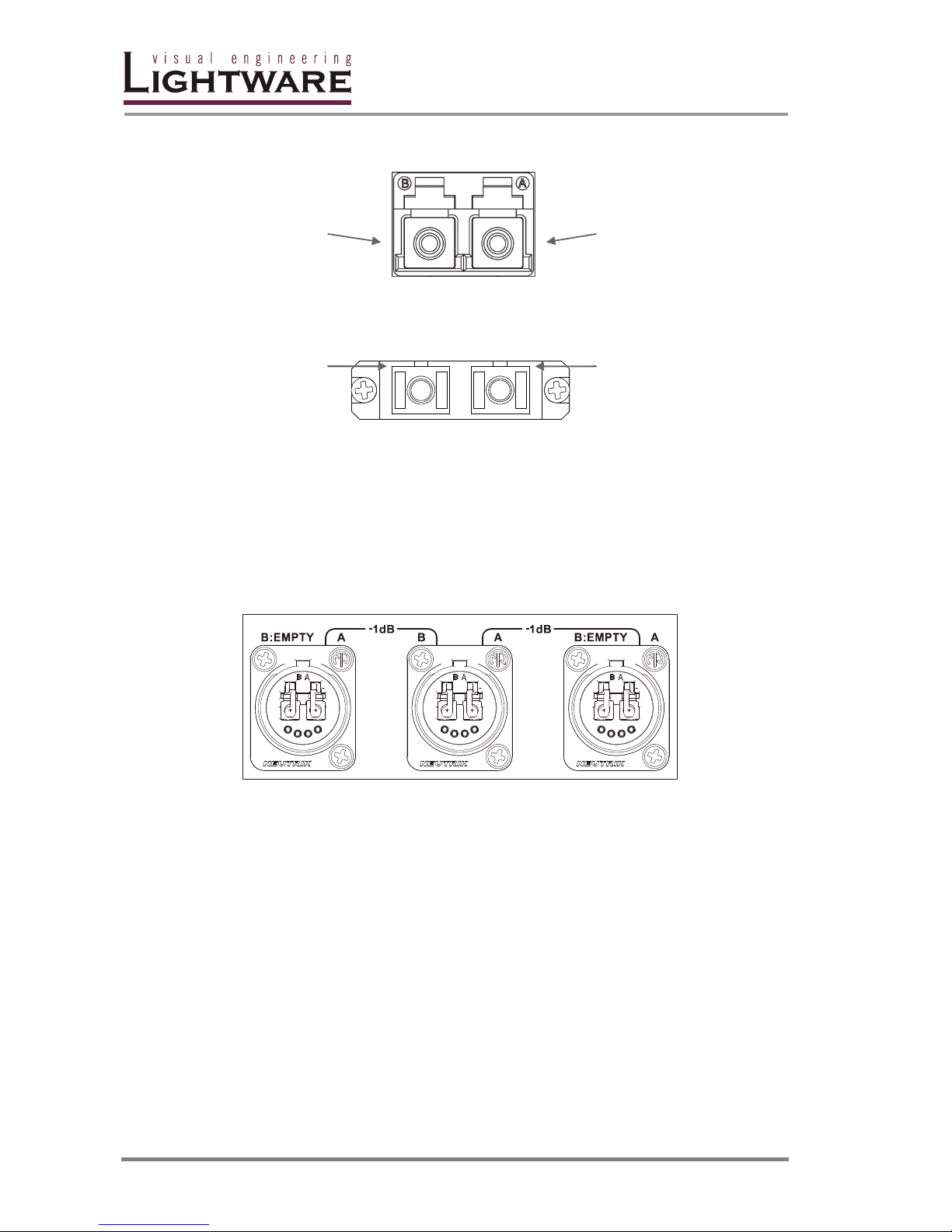
The MX-OPT-HDMI-IB and MX-HDMI-OPT-OB cards can be ordered with either
Neutrik NO2-4FD type connector or LC connectors.
Fiber B Fiber A
Neutrik NO2-4FD connector
Fiber B Fiber A
ST connector
Page 24
Page 24 / 109
Fiber B Fiber A
LC connector
Fiber B Fiber A
SC connector
2.8.2. BR-N Optional Neutrik breakout box
Since Neutrik connectors have two independent fibers in one cable, Lightware
offers the BR-NT Optional Neutrik breakout box to separate the individual signals
from each other.
BR-NT Neutrik breakout box
The breakout box is a passive component and it adds 1 dB attenuation to each
fiber.
Page 25
MX32x32DVI-HDCP-Pro and HDMI-Pro
User’s Manual v1.0
Page 25/ 109
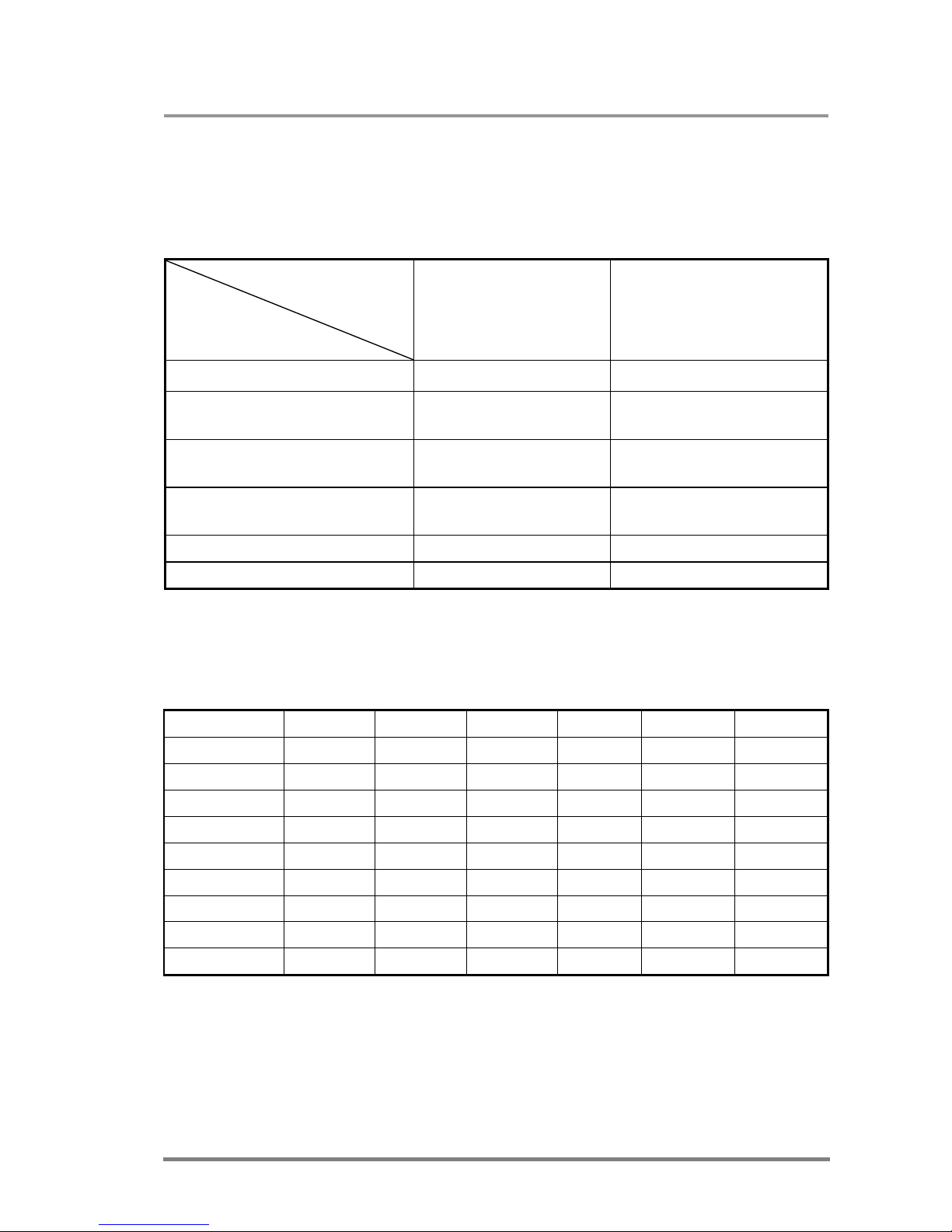
2.8.3. Maximal Cable length at inputs
The unit has an advanced built-in cable compensation circuit, which provides
automatic or manual cable length compensation. This circuit extends the maximum
usable cable length to even 50 meters using high quality 22AWG copper cable at
WUXGA 1920x1200 graphics resolution.
Cable type
Signal
22 AWG
Reference type
DVI GEAR: SHR DVI
24 AWG
Reference type
TASKER: TSK 1060
Resolutions at 24 bits/pixel Max length (meter) Max length (meter)
1920x1200; 1600x1200;
2048x1080p; 1920x1080p
60 m 50 m
1680x1050; 1400x1050;
1280x1024
75 m 62 m
1024x768; 1365x768;
1280x720p; 1920x1080i;
92 m 77 m
800x600
100 m 84 m
640x480; 480p; 576p
120 m 100 m
Maximum DVI or HDMI cable lengths at inputs
The maximum cable lengths at the inputs of the MX-HDMI-TP-IB are shown below:
Resolution Cat5e UTP Cat5e FTP CAT6 UTP CAT6 FTP
CAT6 SFTP CAT7 SFTP
640x480@60
60 m 60 m 65 m 70 m 70 m 80 m
800x600@60
60 m 60 m 65 m 65 m 65 m 75 m
1024x768@60
55 m 55 m 60 m 60 m 60 m 75 m
1280x720p60
55 m 55 m 60 m 60 m 60 m 70 m
1280x1024@60
50 m 50 m 55 m 60 m 60 m 65 m
1400x1050@60
45 m 45 m 45 m 55 m 55 m 60 m
1600x1200@60
30 m 35 m 35 m 45 m 45 m 50 m
1920x1080p60
30 m 35 m 35 m 45 m 45 m 50 m
1920x1200p60
30 m 35 m 35 m 45 m 45 m 50 m
Maximum UTP cable lengths at inputs
The above listed values were measured in 24 bits/pixel mode. The maximal cable
length in deep color modes will be shorter due to the higher data rate.
Page 26

Page 26 / 109
2.8.4. Signal outputs
MX-DVI-HDCP-OB cards provide 29-pole DVI connectors for output connections.
As with standard DVI outputs, the usable cable length is limited, since there is no
output amplification applied. For longer cable runs at the outputs, use fiber optical
extenders or active DVI repeaters/extenders.
MX-HDMI-OB cards provide 19-pole type A HDMI connectors for output
connections. Additionally to each HDMI output, an RCA jack connector is provided
with S/PDIF digital audio signal. Note that embedded audio is still present on HDMI
outputs.
Output reclocking
Each output signal is reclocked and stabilized. Signal reclocking is an essentially
important procedure in digital signal transmission. After passing the reclocker
circuit, the signal becomes stable and jitter-free, and can be transmitted over more
equipment like processors or event controllers. Without reclocking, sparkles, noise,
and jaggies can be seen on the image.
Fiber Cable powering
As a special feature, Pro series matrix switchers provide 500 mA current on +5V
output (pin 14 on DVI output connectors and pin 18 on HDMI output connectors )
which is sufficient to supply power to fiber optical DVI cables. Standard DVI outputs
or VGA cards only supply 55 mA current on +5V output, thus they are unable to
directly power a fiber optical cable.
2.8.5. Power connection
Plug a standard IEC power cord into this connector to connect the switcher to a
100 to 240 Volt AC, 50 Hz or 60 Hz power source.
Page 27
MX32x32DVI-HDCP-Pro and HDMI-Pro
User’s Manual v1.0
Page 27/ 109
2.8.6. RS-232/422 and Ethernet control port
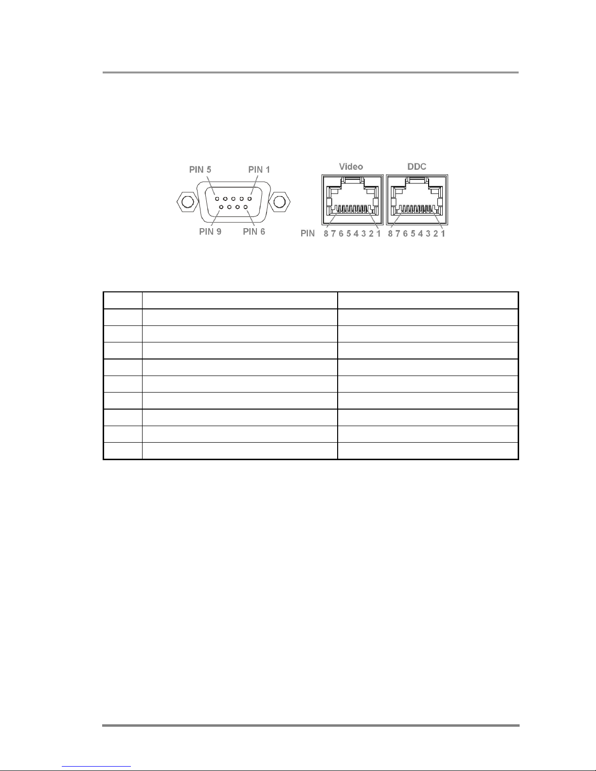
Lightware Pro series matrix switchers can be remote controlled through industry
standard 9-pole D-sub female connector located on the rear panel of the unit. The
router can be ordered with RS-232 or RS-422 control port.
RS-232 and RJ45 connector pin locations
Pin nr. RS-232 RS-422
1
NC non connected TX- data transmit complement
2 TX data transmit
TX+ data transmit true
3 RX data receive
RX+ data receive true
4
DTR internally connected to Pin 6 RX- data receive complement
5 GND signal ground (shield)
GND signal ground (shield)
6
DSR internally connected to Pin 4 NC non connected
7
RTS internally connected to Pin 8 NC non connected
8
CTS internally connected to Pin 7 NC non connected
9
NC non connected NC non connected
RS-232 and RS-422 pin connections
For IP based Ethernet control use the RJ45 connector. IP based commands are
identical to RS-232 control commands. For more information please read the
Programmer’s reference.
Page 28

Page 28 / 109
3. OPERATION
3.1. POWER
Connect the power cord to the router’s IEC standard power input connector. The
router is immediately powered ON when the power cord is connected to the AC
source.
During the initial self-test and loading of the latest settings ,,Booting…” appears on
the LCD screen. After the self-test, the router reloads its last configuration and it is
ready to use. In case of hardware failure, an error message is displayed.
Info: After switching ON, the router reloads the latest settings that were used before it
was turned off. The router has an internal emergency memory that stores all
current settings and tie configurations. This memory is independent from presets
and invisible for the user. This built-in feature helps the system to be ready
immediately in case of power failure or accidental power down.
3.2. FRONT PANEL OPERATIONS
3.2.1. TAKE / AUTOTAKE modes
The router has two different switching modes: TAKE and AUTOTAKE. If the TAKE
button is unlit, TAKE mode is active. When the TAKE button continuously
illuminates green, AUTOTAKE mode is selected.
Press and hold the TAKE button for two seconds to change between TAKE and
AUTOTAKE modes.
TAKE mode allows the user to make multiple connections and deselections at
once. This mode is useful when time delay is not allowed during multiple switching.
After selecting the inputs and outputs, all of the switching actions occur at once.
AUTOTAKE mode is useful when immediate actions must be done or fast
switching is needed between sources on a particular destination. In this mode
switching occurs immediately upon pressing one of the input selector buttons.
3.2.2. CONTROL LOCK
Front panel button operation can be enabled or disabled using CONTROL LOCK
button, while RS-232/422 control is still enabled. If the button is unlit, front panel
button operation is enabled. If it continuously illuminates red then front panel
operations are inhibited.
Press and release CONTROL LOCK button to toggle between the control lock
states.
Page 29

MX32x32DVI-HDCP-Pro and HDMI-Pro
User’s Manual v1.0
Page 29/ 109
3.2.3. SWITCHING
Creating a connection or multiple connections in TAKE mode
1. First press and release the selected source button. The pressed source
button and all destination buttons, which are currently connected to this
source, will light up. The remaining unlit destination buttons are not
connected to this source. This is an informative display about current status
of the selected input. (view only)
2. Press and release the selected unlit destination button or buttons, which
have to be connected to the selected source. The preselected destination
button(s) start(s) blinking.
3. Press and release TAKE button to execute the tie or ties. Now the selected
input is switched to the selected output or multiple outputs.
Deselecting or muting in TAKE mode
1. First press and release the selected source button. The pressed source
button and all destination buttons, which are currently connected to this
source, will light up. The remaining unlit destination buttons are not
connected to this source. This is an informative display about current status
of the selected input. (view only)
2. Press and release the selected, green illuminated destination button which
has to be disconnected from the selected source. The corresponding
button(s) of the pressed destination or multiple destinations will turn dark.
3. Press and release TAKE button to execute disconnection.
Info: Deselected destinations are disconnected from any source, thus output devices will
display black image or "no signal" message and may automatically turn off.
Info: Multiple switching and deselecting actions can be done simultaneously, during only
one TAKE action.
Creating a connection in AUTOTAKE mode
1. Press and release the selected destination button. The pressed destination
button, and the actually connected source button are illuminating green. If no
source is connected, (the output is muted) no source button will light up.
2. Press and release the selected input button. The switch action will be
executed immediately. Switching between sources to the selected
destination can be done directly.
Deselecting or muting in AUTOTAKE mode
1. Press and release the selected destination button. The pressed destination
button, and the actually connected source button are illuminating green. If no
source is connected, (the output is muted) no source button will light up.
2. Press and release the active, green illuminating source button. The output is
muted.
Info: Deselected destinations are disconnected from any source, thus output devices will
display black image or "no signal" message and may automatically turn off.
Page 30

Page 30 / 109
3.2.4. SAVE or LOAD PRESETS
The unit has 32 user programmable presets. Each preset stores a configuration
regarding all input connections for all outputs. All presets are stored in a nonvolatile memory. The router keeps presets even in case of power down. Memory
numbers are assigned to source buttons. (1 to 32 in MX32x32 frame, 1 to 16 in
MX16x16 frame or 1 to 8 in the MX8x8 family.
Saving a Preset in TAKE mode
1. Press and release SAVE PRESET button.
2. Press and release the desired source (memory address) button (source 1 to
32 or to 16)
3. Press and release TAKE button. Now the current configuration is stored in
selected memory.
Info: Preset save action always stores the current configuration for all outputs.
Loading a Preset in TAKE mode
1. Press and release LOAD PRESET button.
2. Press and release the desired source (memory address) button (source 1 to
32 or to 16)
3. Press and release TAKE button. Now the selected preset is loaded.
Info: Loading a preset always modifies all output states.
Saving a Preset in AUTOTAKE mode
1. Press and release SAVE PRESET button.
2. Press and release the desired source (memory address) button (source 1 to
32 or to 16). Now the current configuration is stored in the selected memory.
Info: Preset save action always stores the current configuration for all outputs.
Loading a Preset in AUTOTAKE mode
1. Press and release LOAD PRESET button.
2. Press and release the desired source (memory address) button (source 1 to
32 or to 16). Now the selected preset is loaded.
Info: Loading a preset always modifies all output states.
Page 31

MX32x32DVI-HDCP-Pro and HDMI-Pro
User’s Manual v1.0
Page 31/ 109
3.2.5. VIEW crosspoint state
User can check the current switching status on the front panel using front panel
buttons. View mode is slightly different in TAKE or AUTOTAKE modes because of
different switching philosophy of the two modes.
Info: View mode does not mean, that the router has to be switched in different modes,
viewing and switching can be done after each other, without pressing any special
buttons.
View current state in TAKE mode
If the router is in TAKE mode, user can verify both input and output connections. In
TAKE mode no accidental change can be done unless TAKE button is pressed.
Press and release a source button. Now the selected source button and all
destination buttons that are currently connected to the selected source will light up.
This informative display will remain active for 5 seconds, then all buttons turn unlit.
If every source, destination and TAKE button is unlit (the unit is in TAKE mode, and
no input was selected in the last 5 seconds), press and release a destination
button to see its current state. Now the source button, which is connected to the
selected destination, will light up. If no source button is illuminated, the selected
destination is in muted state. Upon pressing another destination button, the last
state of the destination can be seen.
View current state in AUTOTAKE mode
In AUTOTAKE mode only states of destinations can be viewed.
Press and release the required destination button. Now the source button, which is
connected to the selected destination, will light up. If no source button is
illuminated, the selected destination is in muted state. Upon pressing another
destination button, the last state of the destination can be seen.
3.2.6. VIEW live inputs and attached monitors
1. Press and release SOURCE PRESENT button.
2. Input buttons will light up indicating that active TMDS clock signal is present
on respective input connectors.
Output buttons will light up indicating that a powered monitor is attached to
the output. The output circuit senses TMDS pull-up resistors on monitor side.
3. Press and release SOURCE PRESENT button to quit this mode.
Page 32

Page 32 / 109
3.2.7. OUTPUT LOCK
Using Lightware routers it is possible to lock a destination. This feature prevents an
accidental switching to the locked destination in case of an important signal.
Locking a destination means that no input selection or muting action can be
executed on that particular destination.
Destinations can be independently locked or unlocked. Locking a destination does
not affect other destinations.
Output Lock in TAKE mode
1. Press and release the desired destination button. Now the selected
destination button and the currently configured source button light up. (view
mode)
2. Press and release the Output Lock button. Now the Output Lock button lights
up in red.
3. Press and release TAKE button. The desired destination is now locked.
Unlock in TAKE mode
1. Press and release the desired destination button, which was previously
locked. Now the selected destination button, the currently configured source
button, and the Output Lock button light up.
2. Press and release the Output Lock button (deselect). Now the Output Lock
button turns off, however the locking function has not been cancelled yet.
3. Press and release TAKE button. The desired destination is now unlocked.
Output Lock in AUTOTAKE mode
1. Press and release the desired destination button. Now the selected
destination button and the currently configured source button light up. (view
mode)
2. Press and release the Output Lock button. Now the Output Lock button lights
up in red, and lock function is activated. No source can be switched to the
locked destination.
Unlock in AUTOTAKE mode
1. Press and release the desired destination button, which was previously
locked. Now the selected destination button, the currently configured source
button, and the Output Lock button light up.
2. Press and release the Output Lock button (deselect). Now the Output Lock
button turns off, and the locking function has been cancelled.
Page 33

MX32x32DVI-HDCP-Pro and HDMI-Pro
User’s Manual v1.0
Page 33/ 109
3.3. Front panel LCD Menu operation
3.3.1. Basic concept
There are three operation modes of the LCD menu:
Normal mode Most settings can be done in this mode. It activates after
powering on.
EDID mode Use this mode to set up the emulated EDID on the inputs,
learn EDID form the outputs or to view the EDID memory.
This mode is activated when EDID button is illuminated.
You can enter this mode or exit by pressing the EDID
button.
Signal present mode This mode is for checking the presence of the display
devices and incoming signals. It is activated when
SIGNAL PRESENT button is illuminated. You can enter
this mode or exit by pressing SIGNAL PRESENT button.
Press the LEFT or the RIGHT button to jump between the menus and parameters
Use the ENTER or TAKE buttons to enter a menu or execute an item. The UP and
DOWN buttons modify the values if modification is enabled.
LCD menu
Normal mode
Default display
IP settings
IP address
IP port
IP subnet
IP gateway
Power status
Installed cards
Firmwares
Factory resets
IP reset
IO card reset
HDCP reset
EDID reset
EDID mode
Edid view
Edid save
EDID switch
Signal present mode
LCD menu structure
Page 34
Page 34 / 109
3.3.2. Normal mode
The normal mode has six submenus that can be selected by pressing LEFT and
RIGHT buttons.
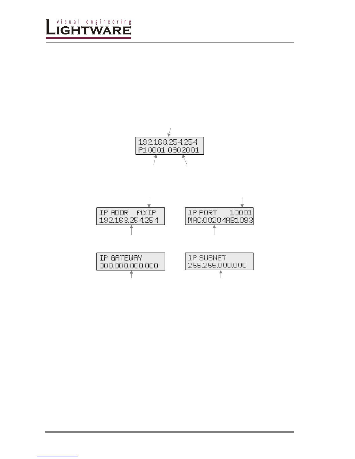
Default display
Default display activates after power up or after 40sec idle from any menu in
normal mode. This screen shows the current IP address, the IP port and the serial
number of the matrix.
Current IP Address
Current Serial number
IP port
IP Settings
fix IP or DHCP IP Port
IP address Media Access Control (MAC)
address
IP Gateway address IP Subnet mask
You can specify the LAN settings in the IP settings menu. Here you can set the IP
address, the IP Port, the IP subnet mask and the IP gateway. Browsing between
these settings is done with the LEFT and RIGHT buttons and selection is done by
pressing ENTER. After the desired modification, you have to press ENTER again
and select the SAVE&EXIT item in the menu, then the new settings will be
activated after a few seconds. If you select the EXIT NO SAVE menu, then no
modifications will be made.
It is possible to configure the system to use DHCP server by selecting DHCP
instead of fixIP.
Note: New settings cannot be applied while an active connection is alive on the Ethernet
port. If you get ,,OPERATION FAILED” message then please disconnect the
remote TCP/IP sockets and try again.
Page 35
MX32x32DVI-HDCP-Pro and HDMI-Pro
User’s Manual v1.0
Page 35/ 109
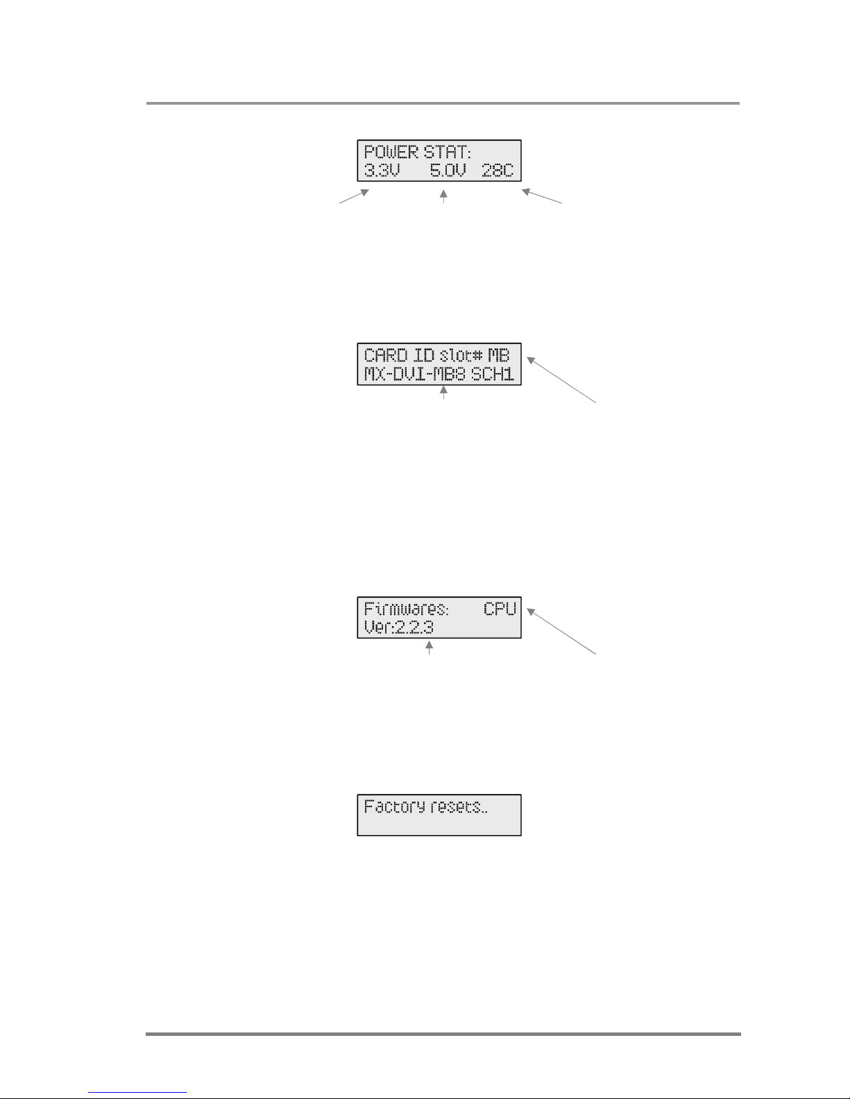
Power status
Internal 3.3V supply Internal 5.0V supply Internal temperature
You are able to check here the DC voltages and the internal temperature. If these
values are out of the safe interval, you will get a warn message on the LCD screen
regardless of what menu is selected.
Cards ID slot
Card name and version Position (MB, I1-I4, O1-O4)
This submenu shows the hardware description strings of the installed cards. You
can view the installed cards by pressing UP and DOWN buttons. The position is
shown in the top right corner. The possible values are:
MB Motherboard
I1, I2, I3, I4 Input card slots
O1, O2, O3, O4 Output card slots
Firmwares
Firmware version Name
It shows the firmware version numbers of the CPU, EDID, web server, web content
and the front panel control board(s). Press the UP and DOWN buttons to view the
desired firmware.
Factory resets
Here you are able to recover the original factory settings if something went wrong.
There are more factory reset options that you can select:
IP reset It resets the IP settings to factory default.
(192.168.254.254:10001, mask:255.255.0.0, no gateway)
IO Card reset Resets all settings related to the IO cards except the
EDID routings.
HDCP reset Resets the internal HDCP key cache. It is useful when a
source device fails because of too many downstream
connections.
Page 36
Page 36 / 109
EDID reset Resets the EDID on all input ports to factory default.
(LWR [email protected] UniversalEDID)
3.3.3. EDID mode
EDID mode is active when the EDID button is illuminated on the front panel. To
enter or to exit from this mode press and release the EDID button.
There are three submenus in this mode, use the RIGHT, LEFT and ENTER buttons
to reach them.
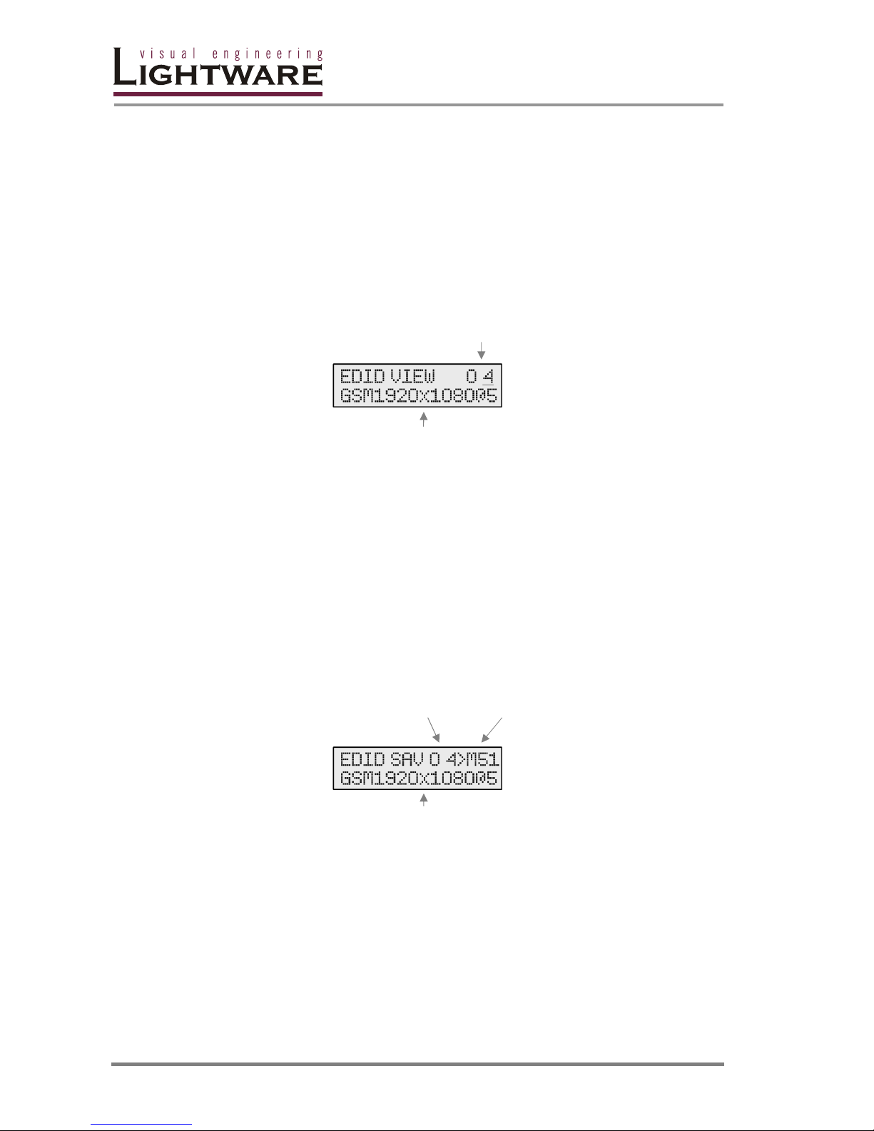
EDID view
EDID memory location
EDID short name
You can select an EDID with the UP and DOWN buttons and view it’s short name.
The short name contains the three-character long manufacturer code (so called
PNPID), the resolution and frame rate of the preferred timing, detailed timing and
the model name descriptor string. The following EDIDs can be selected:
O1 - O32 The EDID of the currently attached or the last attached
sink device.
I1 - I32 The emulated EDIDs of the input ports.
M1 - M50 The stored Lightware EDIDs.
M51 - M100 50 user programmable memory slots.
EDID save
Source Destination
EDID short name
Lightware matrices have 50 user programmable EDID memory slots. You can learn
and save an EDID from any output to one of the M51-M100 memory slots. You
have to select the desired output and the desired destination, then press ENTER.
The EDIDs are stored in the non-volatile emergency memory. By default all user
programmable memory slots are empty.
Press the EDID button to exit.
Page 37
MX32x32DVI-HDCP-Pro and HDMI-Pro
User’s Manual v1.0
Page 37/ 109
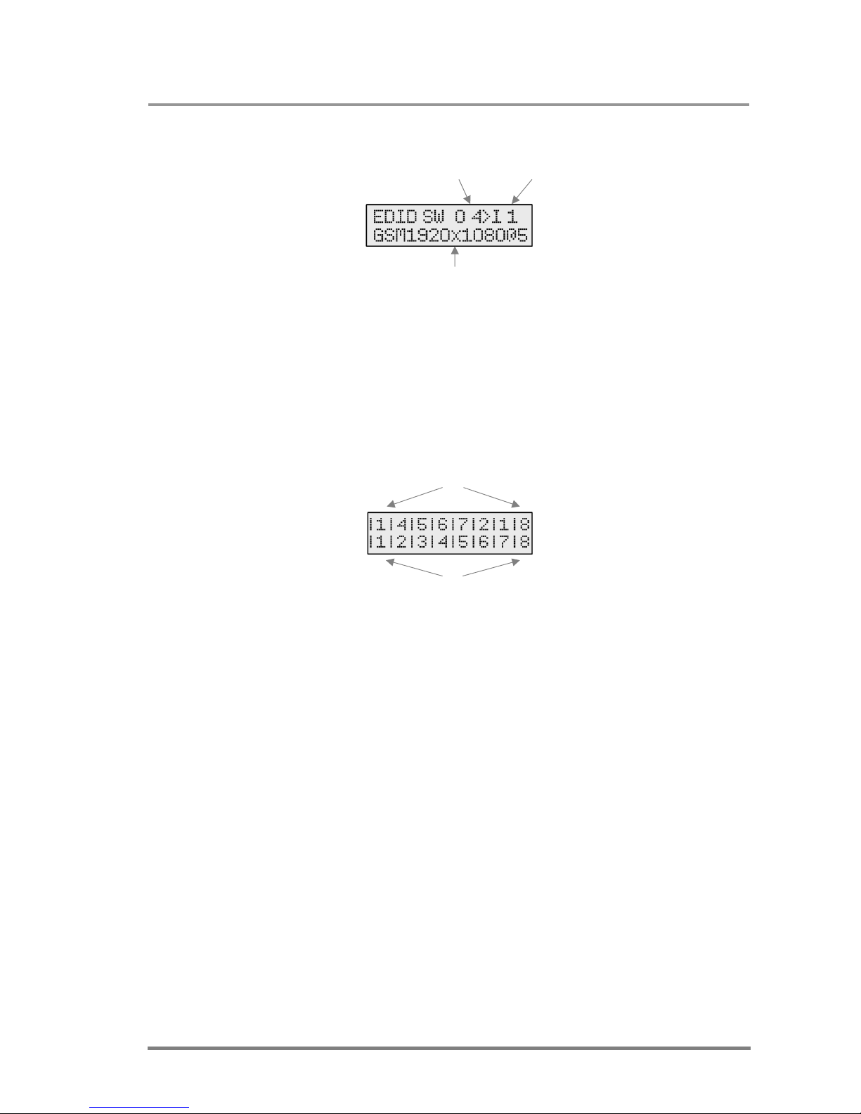
EDID switch
Source Destination
EDID short name
This menu is used to select the emulated EDIDs on the inputs. You have to specify
the EDID source and the desired input port then press ENTER.
If you select an output port as source then dynamic routing will be performed: the
input will follow the changes of the output port. If there is no connected device on
the selected output, then the EDID of the last attached sink will be emulated.
Press the EDID button to exit this menu.
3.3.4. Signal Present mode
The selected input port numbers
The output ports
Signal present mode is active when Signal present button is illuminated. To enter
or exit from Signal present mode you have to press this button.
The LCD screen shows the actual connections between the inputs and outputs.
The second line represents the output and the first line represents the connected
inputs. Only 8 connections can be displayed simultaneously. If your matrix has
greater I/O sizes, press the LEFT and RIGHT buttons to switch between the pages.
If you are in Signal Present mode, the source and destination buttons show the
actual state of the matrix. If a source button is illuminated then SCDT is present on
that source. If a destination button is illuminated then a powered display is attached
to this output (Hot Plug Detect signal is present). You can quickly check the cable
connections with this feature.
Page 38

Page 38 / 109
4. Programmer’s reference
Port settings
MX32x32DVI-Pro can be ordered with either RS-232 or RS-422 communication
port. The port settings are done during manufacturing. D-sub connector pin
assignments can be found in chapter 2.8.6.
The device uses standard RS-232 interface with the following settings:
9600 Baud, 8 data bit, No parity, 1 stop bit
null modem cable
The matrix also has a built-in ethernet port with TCP/IP support. See the chapter
about IP settings on page 34 to see how you can set the port number and IP
address. Only one socket is allowed on the Ethernet port at one time, however it is
possible to use the serial and the LAN connection simultaneously. In this case, the
router initiated notifications and the answers for all commands will be sent to both
interfaces.
Changing and viewing protocols
MX32x32DVI-Pro is equipped with multiple router protocols.
1. Switch the router to TAKE mode if it was previously used in AUTOTAKE
mode by pressing TAKE button for 2 seconds. (TAKE will not be illuminated
continuously)
2. Press and release Control Lock. (Control Lock button is continuously
illuminated red)
3. Press and hold Output Lock button. Now one of the source buttons will light
up (view protocol):
If Source #1 button is illuminated: Lightware protocol is active
If Source #2 button is illuminated: Protocol#2 is active
4. While Output Lock is held, press the desired Source button according to the
new protocol. The desired Source button starts blinking and the router
performs a reset. Now the new protocol is active.
The protocol description hereinafter stands for Lightware protocol.
The matrices accept commands surrounded by curly brackets - { } - and responds
with data surrounded by round brackets - ( ) – but only if a command was
successfully interpreted. Input, output numbers and values must be sent as two
digit ASCII numbers.
Legend for control commands:
<in> = input number in 1 or 2 digit ASCII format (01,5,07,16 etc.)
<out> = output number in 1 or 2 digit ASCII format
<in²> = input number in 2 digit ASCII format (01, 02, 10, 12 etc.)
<out²> = output number in 2 digit ASCII format (01, 02, 10, 12 etc.)
<loc> = location number in 1, 2 or 3 digit ASCII format
<id> = id number in 1 or 2 digit ASCII format
<id²> = id number in 2 digit ASCII format
Page 39

MX32x32DVI-HDCP-Pro and HDMI-Pro
User’s Manual v1.0
Page 39/ 109
CrLf = Carriage return, Line feed (0x0D,0x0A)
● = space character (0x20)
→ = each command issued by the controller
← = each response received from the router
Page 40
Page 40 / 109
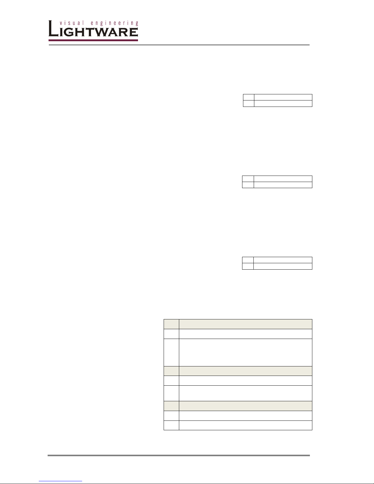
4.1. Switching and control commands
4.1.1. Switch one input to one output
Description: Switch input <in> to output <out>.
Example: Connect input 1 to output 5.
Info: Response <in>, <out> are always in 2 digit
format
4.1.2. Switch one input to all outputs
Description: Switch input <in> to all outputs.
Example: Switch input 1 to all outputs.
4.1.3. View connection on the specified output
Obsolete! Use {VC} instead
Description: View connection on output <out>.
Example: View connection on output 5.
4.1.4. View connection on all outputs
Description: Indexes
show the actual output
and the number at the
given index shows
which input is
connected to it. If value
O5 equals 04 it means
that output 5 is
connected to input 4.
→ {<in>@<out>}
← (O<out²>●I<in²>)CrLf
→ {1@5}
← (O05 I01)CrLf
→ {<in>@O}
← (I<in²>●All)CrLf
→ {01@O}
← (I01 All)CrLf
→ {?<out>}
← (O<out²>●I<in²>)CrLf
→ {?05}
← (O05 I01)CrLf
MX32x32
→ {VC}
←
(ALL●O1●O2●O3●O4●O5●O6●O7●O8●
O9●O10●O11●O12●O13●O14●O15●O16●
O17●O18●O19●O20●O21●O22●O23●O24●
O25●O26●O27●O28●O29●O30●O31●O32)CrLf
MX16x16
→ {VC}
←
(ALL●O1●O2●O3●O4●O5●O6●O7●O8●
O9●O10●O11●O12●O13●O14●O15●O16)CrLf
MX8x8
→ {VC}
←
(ALL●O1●O2●O3●O4●O5●O6●O7●O8)CrLf
Page 41
MX32x32DVI-HDCP-Pro and HDMI-Pro
User’s Manual v1.0
Page 41/ 109
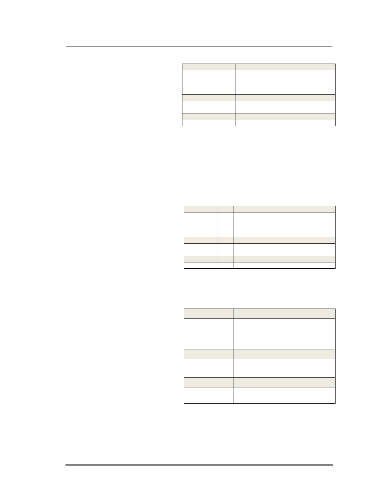
Example 1: View connection on all outputs
Legend 1: output 1 is
connected to input 1,
output 2 is connected
to input 2...output 32 is
connected to input 32,
this is the so-called
„diagonal pattern”.
Info: Note that a space character is sent after the last output
Info: If an output is locked, muted, or both (locked AND muted), the response format
changes. If outputs are muted you get a letter 'M', if locked a letter 'L' and if muted
and locked at the same time 'U' before the 2 digit numbers.
Info: The router will always respond 32 output states regardless of the installed output
cards, as the number of outputs correlates to the frame and not to the number of
installed outputs.
Example 2:
Legend 2:
The connections are
almost the same as in
example 1, but output 1
is muted, output 2 is
locked to input 2 and
output 3 is muted, and
locked to input 3.
4.1.5. View mutes on all outputs
Description: The length
of the response
depends on the number
of outputs installed in
the router. The
response above
presumes a router
having 32 outputs.
Indexes show the actual
output and the number
at the given index
shows its state. If the
value M5 equals 1, it
means that output 5 is
muted, if 0, output 5 is
not muted.
MX32x32
→ {VC}
←
(ALL 01 02 03 04 05 06 07 08
09 10 11 12 13 14 15 16
17 18 19 20 21 22 23 24
25 26 27 28 29 30 31 32 )CrLf
MX16x16
→ {VC}
←
(ALL 01 02 03 04 05 06 07 08
09 10 11 12 13 14 15)CrLf
MX8x8
→ {VC}
← (ALL 01 02 03 04 05 06 07 08)CrLf
MX32x32
→ {VC}
←
(ALL M01 L02 U03 04 05 06 07 08
09 10 11 12 13 14 15 16
17 18 19 20 21 22 23 24
25 26 27 28 29 30 31 32 )CrLf
MX16x16
→ {VC}
←
(ALL M01 L02 U03 04 05 06 07 08
09 10 11 12 13 14 15)CrLf
MX8x8
→ {VC}
← (ALL M01 L02 U03 04 05 06 07 08)CrLf
MX32x32
→ {VM}
←
(MUT●M1●M2●M3●M4●M5●M6●M7●M
8●M9●M10●M11●M12●M13●M14●M15
●M16●M17●M18●M19●M20●M21●M22
●M23●M24●M25●M26●M27●M28●M29
●M30●M31●M32)CrLf
MX16x16
→ {VM}
←
(MUT●M1●M2●M3●M4●M5●M6●M7●M
8●M9●M10●M11●M12●M13●M14●M15
●M16)CrLf
MX8x8
→ {VM}
←
(MUT●M1●M2●M3●M4●M5●M6●M7●M
8)CrLf
Page 42
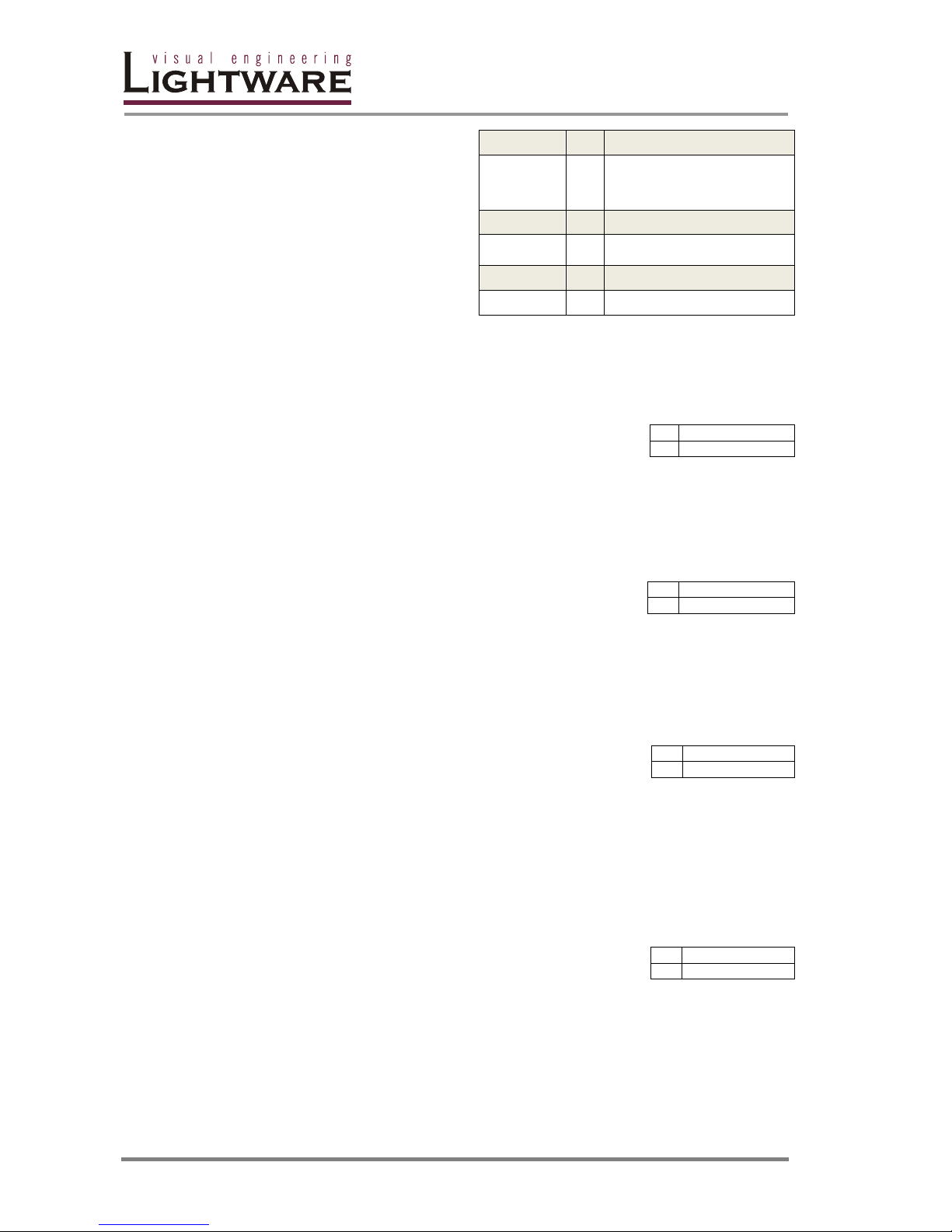
Page 42 / 109
Example: Output 1 and 4 are
muted while the other outputs are
not muted.
4.1.6. Mute specified output
Description: Mute output <out>.
Example: Mute output 5.
4.1.7. Unmute specified output
Description: Unmute output <out>.
Example: Unmute output 5. Now output 5 is
switched to the input it was connected to prior to
the mute.
4.1.8. Lock specified output
Description: Locks output <out>. No other input can be
routed to this output until it is unlocked.
Example: Lock Output 11.
Info: If an output is locked to an input, neither preset
loading nor switching can modify this connection.
4.1.9. Unlock specified output
Description: Unlocks output <out>. Presets can be loaded
to this output and routing is working as well.
Example: Unlock the previously locked output 11.
Info: The router issues the above response regardless of the previous state of the
output <out> (it was either locked or unlocked).
MX32x32
→ {VM}
← (MUT 1 0 0 1 0 0 0 0 0 0 0 0
0 0 0 0 0 0 0 0 0 0 0 0
0 0 0 0 0 0 0 0)CrLf
MX16x16
→ {VM}
← (MUT 1 0 0 1 0 0 0 0 0 0 0 0
0 0 0 0)CrLf
MX8x8
→ {VM}
← (MUT 1 0 0 1 0 0 0 0)CrLf
→ {#<out>}
← (MUT<out²>)CrLf
→ {#05}
← (MUT05)CrLf
→ {+<out>}
← (UMT<out²>)CrLf
→ {+05}
← (UMT05)CrLf
→ {#><out> }
← (1LO<out²>)CrLf
→ {#>11}
← (1LO11)CrLf
→ {+<<out> }
← (0LO<out²>)CrLf
→ {+<11}
← (0LO11)CrLf
Page 43
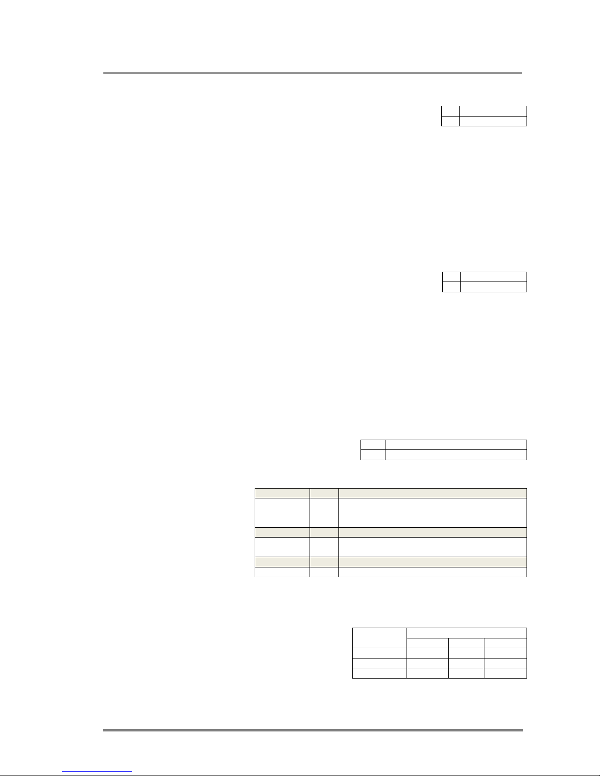
MX32x32DVI-HDCP-Pro and HDMI-Pro
User’s Manual v1.0
Page 43/ 109
4.1.10. Save preset to the specified memory location
Description: Save current ties to preset zz.
Example: Save current connections to preset
memory 7.
Info: The router saves the mute state of the outputs as well.
Info: Lock states are not saved. Lock state is assigned to the physical output of the
router. Presets don’t affect output locks.
4.1.11. Load preset from the specified location
Description: Load preset zz.
.
Example: Load connections previously saved to
preset memory 7. All connections will be reloaded.
Info: The router loads the mute state of the outputs as well.
Info: Lock states are not loaded. Lock state is assigned to the physical output of the
router. Presets don’t affect output locks.
4.1.12. View preset without loading
Description: View the specified preset
without loading it.
Examples:
4.1.13. Name Presets / Inputs / Outputs
Description: Allows storing names for
each preset / input / output. Any 16byte long string is allowed. All
characters are converted to uppercase!
The router accepts <id> greater than
the current I/O setup but treats it as modulo output. So if <id> = 9 on a 8x8 router,
then it will be treated as 1.
→ {$<id>}
← (SPR<id²>)CrLf
→ {$07}
← (SPR07)CrLf
→ {%<id>}
← (LPR<id²>)CrLf
→ {%07}
← (LPR07)CrLf
→ {VP#<id>=?}
←
(VP#<id>=●01●02●03●... ●32)CrLf
MX32x32
→ {VP#1=?}
← (VP#1= M01 L02 U03 04 05 06 07 08 09 10 11
12 13 14 15 16 17 18 19 20 21 22 23 24 25 26
27 28 29 30 31 32 )CrLf
MX16x16
→ {VP#1=?}
← (VP#1= M01 L02 U03 04 05 06 07 08 09 10 11
12 13 14 15)CrLf
MX8x8
→ {VP#1=?}
← (VP#1= M01 L02 U03 04 05 06 07 08)CrLf
valid <id> field
Preset Input Output
MX32x32
1..32 1..32 1..32
MX16x
16
1..32
1..16 1..16
MX8x8
1..32 1..8 1..8
Page 44
Page 44 / 109
Name a preset:
Example:
Name an input:
Example:
Name an output:
Example:
4.1.14. Query names of Presets / Inputs / Outputs
Description: Each preset / input / output name can be read from the router.
Query a preset name:
Example:
Query input name:
Example:
Query output name:
Example:
4.1.15. Set default names of Presets / Inputs / Outputs
Description: Renames all preset / input / output names to the default setup Preset
1..32 / Input 1.. / Output 1.. respectively.
Info: <id> field has no meaning here, but has to be a valid one!
Set default preset names:
→
{PNAME#<id>=<preset_name>}
←
(PNAME#<id>=<preset_name>)CrLf
→
{
PNAME
#1=first preset}
←
(
PNAME
#1=FIRST PRESET)CrLf
→
{
INAME
#<id>=<input_name>}
←
(
INAME
#<id>=<input_name>)CrLf
→
{
INAME
#1=first input}
←
(
I
NAME
#1=FIRST INPUT)CrLf
→
{
ONAME
#<id>=<output_name>}
←
(
ONAME
#<id>=<output_name>)CrLf
→
{
ONAME
#1=first output}
←
(
ONAME
#1=FIRST OUTPUT)CrLf
→
{
PNAME
#<id>=?}
←
(
PNAME
#<id>=<preset_name>)CrLf
→
{
PNAME
#1=?}
←
(
PNAME
#1=Preset 1)CrLf
→
{
INAME
#<id>=?}
←
(
INAME
#<id>=<input_name>)CrLf
→
{
INAME
#1=?}
←
(
INAME
#1=Input 1)CrLf
→
{
ONAME
#<id>=?}
←
(
ONAME
#<id>=<output_name>)CrLf
→
{
INAME
#1= ?}
←
(
INAME
#1=Output 1)CrLf
→
{
PNAME
#<id>=!}
←
(
PNAME
#<id>=Preset<id>)CrLf
Page 45
MX32x32DVI-HDCP-Pro and HDMI-Pro
User’s Manual v1.0
Page 45/ 109
Example:
Set default input names:
Example:
Set default output names:
Example:
4.1.16. Query IP settings
Description: IP setup can be retrieved
from the router with this command.
Legend:
Identifier
Description
Default value
<id> 0-fix IP, 7-DHCP 0
<ip_address> IP address 192.168.254.254
<port> IP port of the router 10001
<mask> subnet mask 255.255.0.0
<gateway> gateway address 0.0.0.0
Example:
Legend: The router has a fix 192.168.2.106 IP address on the 255.0.0.0 subnet
with a gateway on 192.168.2.1 and communicates over port no. 10001.
4.1.17. Reload factory default IP settings
Description: After issuing this
command (either over serial or IP) the
router will reload the factory default IP
setup.
Parameters after successful command execution:
→
{
PNAME
#2=!}
←
(
PNAME
#2=Preset 2)CrLf
→
{
INAME
#<id>=!}
←
(
INAME
#<id>=Input<id>)CrLf
→
{
INAME
#2=!}
←
(
INAME
#2=Input 2)CrLf
→
{
ONAME
#<id>=!}
←
(
ONAME
#<id>=Output<id>)CrLf
→
{
ONAME
#2=!}
←
(
ONAME
#2=Output 2)CrLf
→ {IP_CONFIG=?}
←
(IP_CONFIG=<id>●<ip_address>●
<port>●<mask>●<gateway>)CrLf
→ {IP_CONFIG=?}
← (IP_CONFIG=0 192.168.2.106 10001 255.0.0.0 192.168.2.1)CrLf
→
{IP_CONFIG=!}
← (Changing IP configuration…)CrLf
…4 second delay…
… Beep Beep sound from the router…
← (DONE!)CrLf or (FAILED!)CrLf
Parameter
Value
IP address 192.168.254.254
port number 10001
Subnet mask 255.255.0.0
Gateway 0.0.0.0
Page 46
Page 46 / 109
4.1.18. Load DHCP IP settings (only IP address!)
Description: After issuing this
command (either over serial or IP) the
router will reload the factory default IP
setup.
Parameters after successful command execution:
4.2. Router Status Commands
4.2.1. View product type
Description: The router responds its name.
Example:
4.2.2. View serial number
Description: The router responds its 8-digit
serial number.
Example: The serial number of the connected
router is: 06050100.
Info: Only the last 4 numbers are written onto the back of the router
4.2.3. View Firmware version of the CPU
Description: View the CPU firmware revision.
To view another controller’s firmware revision
see → ’Query cards' firmware’ {FC}.
Example: The connected router’s CPU has a
firmware version of 1.10.
→
{IP_CONFIG=D}
← (Changing IP configuration…)CrLf
…4 second delay…
… Beep Beep sound from the router…
← (DONE!)CrLf or (FAILED!)CrLf
Parameter
Value
IP address Acquired with DHCP
port number unchanged
Subnet mask unchanged
Gateway unchanged
→ {I}
← (PRODUCT_TYPE)CrLf
MX32x32
→ {I }
← (MX32X32DVI FRAME)CrLf
MX16x16
→ {I}
← (MX16X16DVI FRAME)CrLf
MX8x8
→ {I}
← (MX8X8DVI FRAME)CrLf
→ {S}
← SN:<SERIAL_NUMBER>)CrLf
→ {S}
← (SN:06050100)CrLf
→ {F}
← (FIRMWARE_VERSION)CrLf
→ {F}
← (FW:1.1.0)CrLf
Page 47
MX32x32DVI-HDCP-Pro and HDMI-Pro
User’s Manual v1.0
Page 47/ 109
4.2.4. View Router’s health
Description: Shows power, temperature and fan status of the router.
Legend:
Example:
MX32x32
→ {ST}
← (STAT 3.2V 5.0V 12.1V 23C 1629RPM 1600RPM)CrLf
MX16x16
→ {ST}
← (STAT 3.2V 5.0V 12.1V 23C 1629RPM 1600RPM CrLf
MX8x8
→ {ST}
← (STAT 3.2V 5.0V 23C)CrLf
4.2.5. View Installed I/O cards’ hardware
Description: Shows the hardware name and revision of the installed cards.
Example
:
MX32x32
→ {IS}
←
←
←
←
←
←
←
←
←
(SL#
●0●MB_DESCRIPTOR)CrLf
(SL#
●1●OUTPUT_CARD_DESC)CrLf
(SL#
●2●OUTPUT_CARD_DESC)CrLf
(SL#
●3●OUTPUT_CARD_DESC )CrLf
(SL#
●4●OUTPUT_CARD_DESC)CrLf
(SL#
●5●INPUT_CARD_DESC)CrLf
(SL#
●6●INPUT_CARD_DESC)CrLf
(SL#
●7●INPUT_CARD_DESC)CrLf
(SL#
●8●INPUT_CARD_DESC)CrLf
MX16x16
→ {IS}
←
←
←
←
←
←
←
←
←
(SL#
●0●MB_DESCRIPTOR)CrLf
(SL#
●1●OUTPUT_CARD_DESC)CrLf
(SL#
●2●OUTPUT_CARD_DESC)CrLf
(SL#
●3●EMPTY_SLOT)CrLf
(SL#
●4●EMPTY_SLOT)CrLf
(SL#
●5●INPUT_CARD_DESC)CrLf
(SL#
●6●INPUT_CARD_DESC)CrLf
(SL#
●7●EMPTY_SLOT)CrLf
(SL#
●8●EMPTY_SLOT)CrLf
MX8x8
→ {IS}
←
←
←
←
←
←
←
←
(SL#
●0●MB_DESCRIPTOR)CrLf
(SL#
●1●OUTPUT_CARD_DESC)CrLf
(SL#
●2●EMPTY_SLOT)CrLf
(SL#
●3●EMPTY_SLOT)CrLf
(SL#
●4●EMPTY_SLOT)CrLf
(SL#
●5●INPUT_CARD_DESC)CrLf
(SL#
●6● EMPTY_SLOT)CrLf
(SL#
●7●EMPTY_SLOT)CrLf
(SL#
●8●EMPTY_SLOT)CrLf
MX32x32
→ {IS}
←
←
←
←
←
←
←
←
←
(SL# 0 MX-DVI-MB32 SCH_1.1 PCB_1.1 )CrLf
(SL# 1 MX-DVI-HDCP-OB SCH_1.1 PCB_1.1)CrLf
(SL# 2 MX-DVI-HDCP-OB SCH_1.1 PCB_1.1)CrLf
(SL# 3 MX-DVI-HDCP-OB SCH_1.1 PCB_1.1)CrLf
(SL# 4 MX-DVI-HDCP-OB SCH_1.1 PCB_1.1)CrLf
(SL# 5 MX-DVI-HDCP-IB SCH_1.1 PCB_1.1)CrLf
(SL# 6 MX-DVI-HDCP-IB SCH_1.1 PCB_1.1)CrLf
(SL# 7 MX-DVI-HDCP-IB SCH_1.1 PCB_1.1)CrLf
(SL# 8 MX-DVI-HDCP-IB SCH_1.1 PCB_1.1)CrLf
MX16x16
→ {IS}
←
←
←
←
←
←
←
←
←
(SL# 0 MX-DVI-MB16 SCH_1.1 PCB_1.1)CrLf
(SL# 1 MX-HDMI-OB SCH_1.1 PCB_1.1)CrLf
(SL# 2 MX-HDMI-OB SCH_1.1 PCB_1.1)CrLf
(SL# 3 EMPTY SLOT)CrLf
(SL# 4 EMPTY SLOT)CrLf
(SL# 5 MX-HDMI-IB SCH_1.1 PCB_1.1)CrLf
(SL# 6 MX-HDMI-IB SCH_1.1 PCB_1.1)CrLf
(SL# 7 EMPTY SLOT)CrLf
(SL# 8 EMPTY SLOT)CrLf
MX8x8
→ {IS}
←
←
←
←
←
←
←
←
←
SL# 0 MX-DVI-MB8 SCH_1.1 PCB_1.1)CrLf
(SL# 1 MX-DVI-HDCP-OB SCH_1.1 PCB_1.1)CrLf
(SL# 2 EMPTY SLOT)CrLf
(SL# 3 EMPTY SLOT)CrLf
(SL# 4 EMPTY SLOT)CrLf
(SL# 5 MX-DVI-HDCP-IB SCH_1.1 PCB_1.1)CrLf
(SL# 6 EMPTY SLOT)CrLf
(SL# 7 EMPTY SLOT)CrLf
(SL# 8 EMPTY SLOT)CrLf
MX32x32
→ {ST}
←
(STAT●<V1>●<V2>●<V3>●<temp>●<rpm1>● <rpm2>)CrLf
MX16x16
→ {ST}
←
(STAT●<V1>●<V2>●<V3>●<temp>●<rpm1>● <rpm2>)CrLf
MX8x8
→ {ST}
←
(STAT●<V1>●<V2>●<temp>)CrLf
Identifier
description
default value
<V1>
System voltage
3.3V
<V2>
EDID voltage
5.0V
<V3>
FAN voltage
12V
<temp>
System Temp.in °C
24°C
<rpm1>
FAN1 speed
1600RPM
<rpm2>
FAN2 speed
1600RPM
Page 48
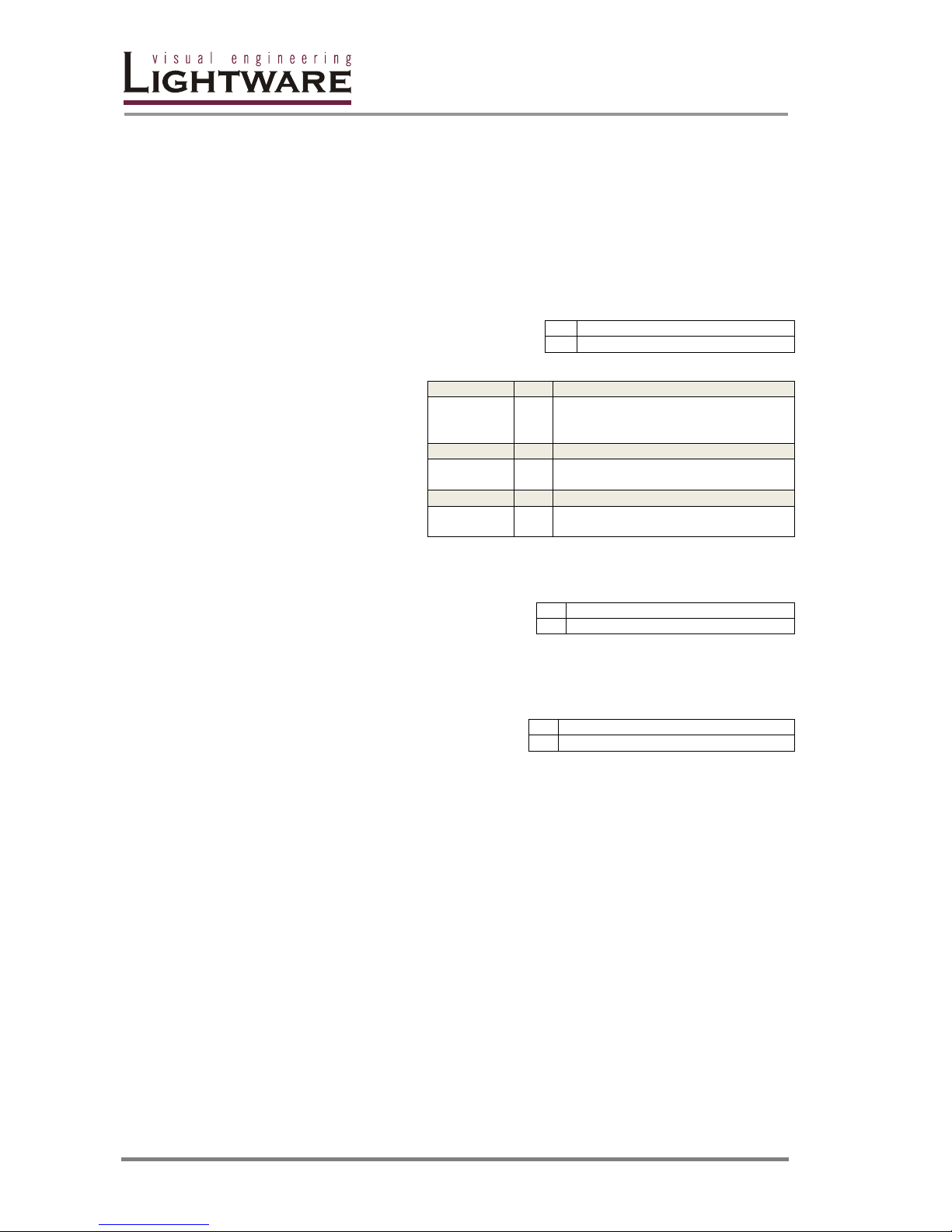
Page 48 / 109
Legend (MX32x32 Frame): The router has 4 input and 4 output cards (32x32)
installed. All cards are DVI-HDCP.
Legend (MX16x16 Frame): The router has 2 input and 2 output cards (16x16)
installed.
Legend (MX8x8 Frame): The router has 1 input and 1 output cards (8x8)
installed.
4.2.6. View installed controllers’ firmware
Description: Shows the firmware revisions
of the installed programmed controllers
Example:
MX32x32
→ {FC}
←
←
←
(CF MX-CP FW:1.0.2 @ 0X10)CrLf
(CF MX-CP FW:1.0.2 @ 0X12)CrLf
(CF MX-DVI-EDID FW:1.1.0 @ 0X20)CrLf
MX16x
16
→ {FC}
←
←
(CF MX-CP FW:1.0.2 @ 0X10)CrLf
(CF MX-DVI-EDID FW:1.1.0 @ 0X20)CrLf
MX8x8
→ {FC}
←
←
(CF MX-CP FW:1.0.2 @ 0X10)CrLf
(CF MX-DVI-EDID FW:1.1.0 @ 0X20)CrLf
4.2.7. View current control protocol
Description: Shows the RS-232, TCP/IP
control protocol.
4.2.8. Set current control protocol
Description: Sets the current RS-232,
TCP/IP control protocol (Default is ’1’)
→ {FC}
← (CF CARD_FIRMWARE)CrLf
→ {P_?}
← (CURRENT PROTOCOL = #1)CrLf
→ {P_x}
← (PROTOCOL #<x> SELECTED!)CrLf
Page 49
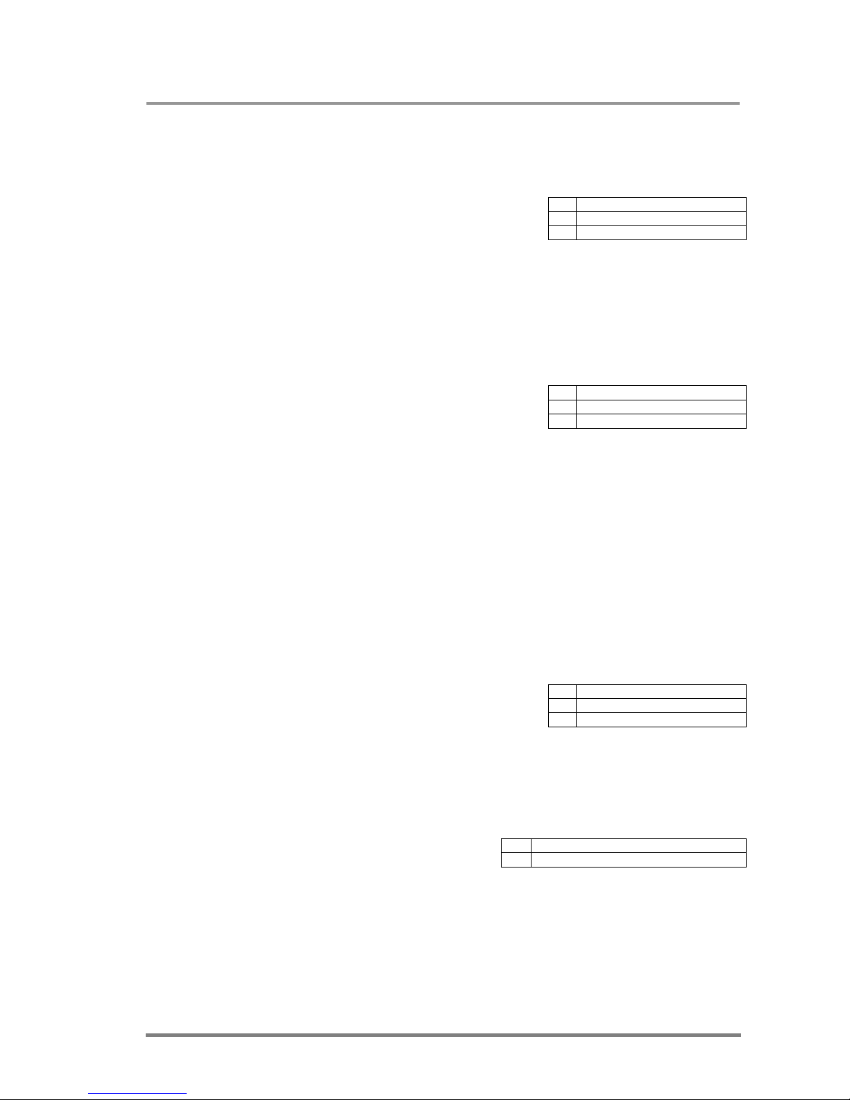
MX32x32DVI-HDCP-Pro and HDMI-Pro
User’s Manual v1.0
Page 49/ 109
4.3. EDID router commands
4.3.1. Route EDID to the selected input (static)
Description: Copies EDID from location <loc>
to input <in>. <loc> must be 1..100
Example:
Note: (E_S_C) arrives only if the new and the old EDID don’t match.
4.3.2. Route EDID to the selected input (dynamic)
Description: It copies EDID from location <loc>
to input <in>. Location <loc> should be
101..132 as opposed to static routing where
<loc> should be between 1..100.
Info: Inputs 1..32 are mapped to logical addresses 101..132
After choosing dynamic EDID routing for one (or all inputs) the router will follow the
EDID changes that occur on the output it is connected to.
Example:
After issuing this command the router will automatically copy the new EDID on
output1 (remember logical address = 101) if it changes.
4.3.3. Route one EDID to all inputs
Description: It copies EDID from the selected
location <loc> to all inputs.
Example:
4.3.4. View EDID switch status on all inputs
Description: Indexes show the actual
input and the number at the given index
(<in1>..<inN>) shows which EDID is
switched to that particular input where N represents the maximal input number of
the given configuration.
Info: The length of <in1>..<inN> is always 3 digits! (001, 010, 100)
→ {<in>:<loc>}
← (E_SW_OK)CrLf
← (E_S_C) CrLf
→ {5:10}
← (E_SW_OK)CrLf
← (E_S_C) CrLf
→ {<in>:<loc>}
← (E_SW_OK)CrLf
← (E_S_C) CrLf
→ {4:101}
← (E_SW_OK)CrLf
← (E_S_C) CrLf
→ {A:<loc>}
← (E_SW_OK)CrLf
← (E_S_C) CrLf
→ {A:48}
← (E_SW_OK)CrLf
← (E_S_C) CrLf
→ {VEDID}
←
(VEDID●<in1>●<in2>●…●<inN>)CrLf
Page 50
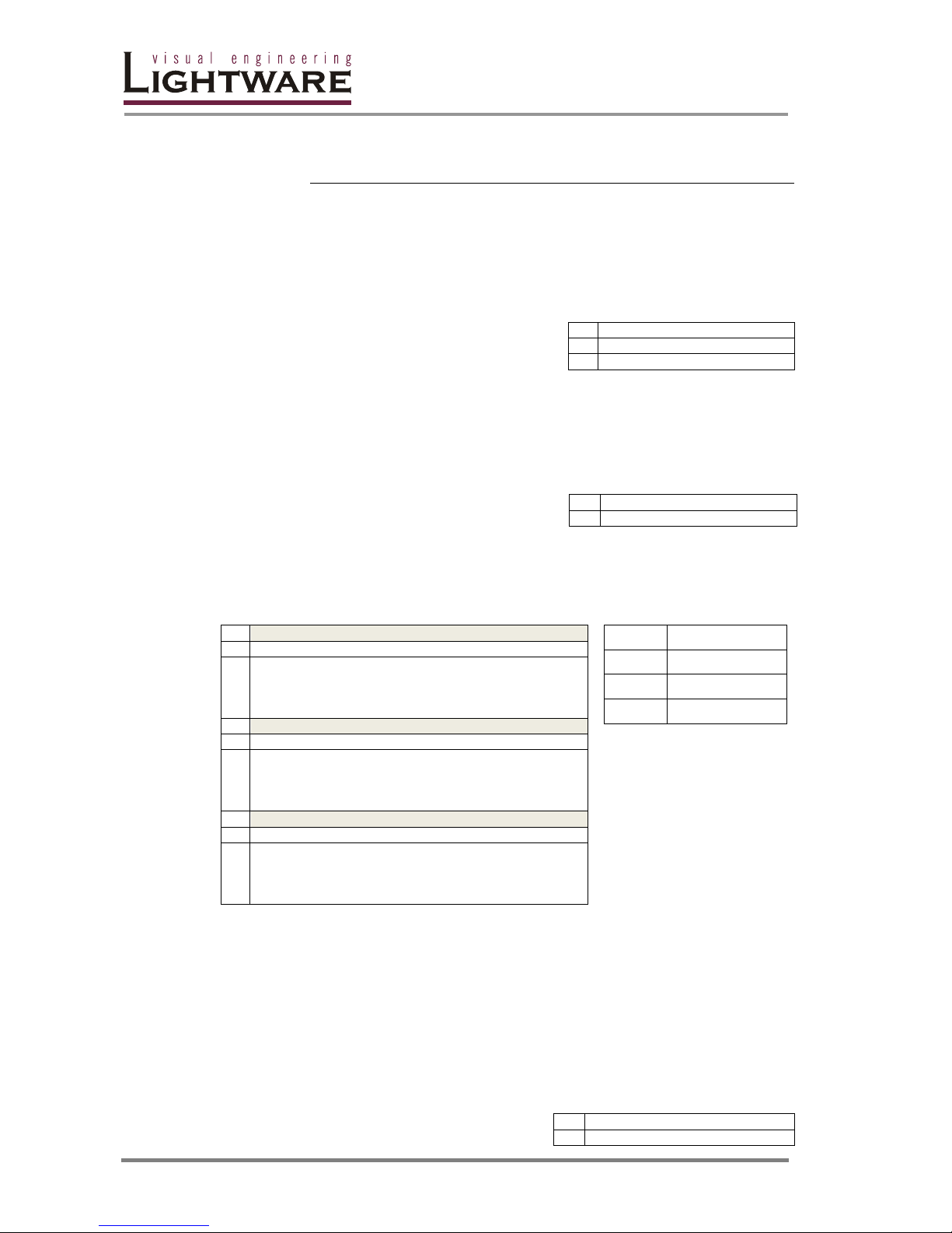
Page 50 / 109
Logical EDID locations:
Factory presets User presets Outputs Inputs
MX32x32
1..50 51..100 101..132 133..164
MX16x16
1..50 51..100 101..116 133..148
MX8x8
1..50 51..100 101..108 133..140
4.3.5. Save EDID from output to memory location (Learn EDID)
Description: Learn EDID from the specified
output <out> to the specified location <loc>.
Example:
4.3.6. View EDID validity table
Description: Shows EDID validity table, which
contains information about the EDID states.
If a changed EDID is queried by the wh command (see the next section), its value
returns to ‘1’.
Example
Legend:
MX32x32
→ {WV}
←
(EV 1111111111111111111111111111111111111111
11111111110003301100000000000000000000000000
00000000000000001331111111111111111111111111
111111111111111133111111111111111111)CrLf
MX16x16
→ {WV}
←
(EV 1111111111111111111111111111111111111111
11111111110003301100000000000000000000000000
00000000000000001331111111111111000000000000
000011111111111133110000000000000000)CrLf
MX8x8
→ {WV}
←
(EV 1111111111111111111111111111111111111111
11111111110003301100000000000000000000000000
00000000000000001331111100000000000000000000
000011111111000000000000000000000000)CrLf
Value
Description
’0’
invalid EDID
’1’
valid EDID
’3’
changed EDID
4.3.7. View EDID header
Description: EDID_HEADER consist of 3
→ {<out>><loc>}
← (E_SW_OK)CrLf
← (E_S_C) CrLf
→ {24>51}
← (E_SW_OK)CrLf
← (E_S_C) CrLf
→ {wv}
← (EV●VALIDITY_TABLE)CrLf
→ {wh<loc>}
← (EH#<loc>●EDID_HEADER)CrLf
Page 51
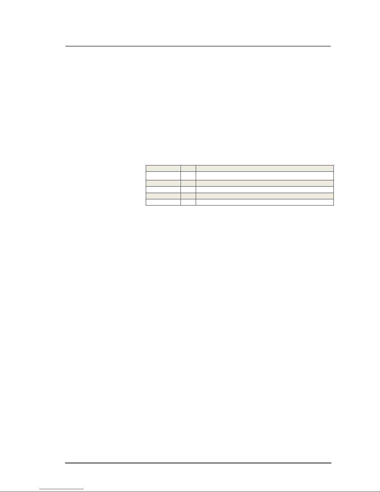
MX32x32DVI-HDCP-Pro and HDMI-Pro
User’s Manual v1.0
Page 51/ 109
fields:
PNPID code The three letter abbreviation of the manufacturer
Preferred resolution The resolution and refresh rate stored in the preferred
detailed timing block.
Name The name of display device stored in product descriptor.
Note: If a CEA extension is present in the EDID, HDMI capable sources such as top-
boxes and BD-players will use the short video descriptors instead of preferred
detailed timing block in order to determine the type of the sent video. Please refer
the standards for more details.
Example:
Show the emulated EDID on DVI input#1 (for more information see session EDID
Management: using EDID Router)
MX32x32
→ {WH133}
← (EH#133 NEC 1600X1200@60 LCD2170NX)CrLf
MX16x16
→ {WH117}
← (EH#117 NEC 1600X1200@60 LCD2170NX)CrLf
MX8x8
→ {WH109}
← (EH#109 NEC 1600X1200@60 LCD2170NX)CrLf
Page 52
Page 52 / 109
Legend:
4.3.8. Upload EDID content from the router
Description: EDID hex bytes can be read
directly. The router will issue the whole
content of the EDID present on memory
location <loc> (256 bytes).
Legend: B1..B256 are space separated hex characters represented in ASCII
format.
Example:
4.3.9. Download EDID content to the router
Description: EDID hex bytes can be written directly to the user programmable
memory locations (locations #51...#100).
Sequence:
• Prepares the router to accept EDID bytes to the specified location <loc>
{WL#<loc>}
• Router responds that it is ready to accept EDID bytes (E_L_S)CrLf
• Send 1 block of EDID (1 block consist of 8 bytes of hex data represented in
ASCII format) {WB#1●B1●B2●B3●B4●B5●B6●B7●B8}
• The router acknowledges (EL#●)
• Send another 31 blocks of EDID (32 altogether)
• After the last acknowledge, the router signals that the EDID status has
changed (E_S_C) CrLf
EDID manufacturer: NEC
Preferred resolution: 1600X1200@60
Display device’s name: 60 LCD2170NX
→ {we<loc>}
← (EB#<loc>●B1●B2●..B256)CrLf
→
{we1}
←
(EB#1 00 FF FF FF FF FF FF 00 32 F2 00 00 00 .. .. .. 00 92)
→ {WL#<loc>}
← (E_L_S)CrLf
→ {WB#1●B1● B2 ●B3●B4●B5●B6●B7●B8}
← (EL#●)CrLf
→ {WB#2●B9● B10 ●B11●B12●B13●B14●B15●B16}
← (EL#●) CrLf
: : :
:
→ {WB#248●B249● B250 ●B251●B252●B253●B254●B255●B256}
← (EL#●) CrLf
← (E_S_C) CrLf
Page 53

MX32x32DVI-HDCP-Pro and HDMI-Pro
User’s Manual v1.0
Page 53/ 109
4.4. Router Initiated commands
4.4.1. EDID status changed∗
Description: This is sent after all commands that
change the EDID (EDID copy, EDID switch), or after a
new EDID source ie. a new display device has been connected to the router.
Example # 1: After routing EDID to a selected output.
Example # 2: After routing EDID to a selected output.
Connecting a new display ie. a new LCD display, to one
output.
Info: The router stores the last attached display device’s EDID connected to the output.
After disconnecting this device its EDID is still present in the router’s memory,
therefore no status change message is issued by the router if a display device
having the same EDID is connected to that output. (The same display device is
connected again, or another display device (same brand) from the the same
manufacturer)
Info: To keep your application in sync with the router it is recommended to issue a show
validity ( {wv} ) → after receiveing EDID status changed response, and read all
locations indicating ’3’ in the table, as the EDID changes triggered the ‘EDID status
changed’ response.
4.4.2. Port Status Changed**
Description: If STATUS_TABLE has changed, the
router will send this sequence to notify the controller
software. This event is useful to trigger the new {:ISD} and {:OSD} commands.
4.4.3. Router ready (after power up or restart)
Description: The router issues this command
after each power up. After this command the
router is ready to accept control commands.
Note: During the booting process (before the ,,Router ready”
message) various messages are sent about the selftest
results. The format of these messages is:
(B:<message>)
Your control software should ignore these strings
because they are useful only in case of hardware
failure.
∗
See session: „EDID Management: using EDID Router”
** See session: „Input and output port status”
← (E_S_C) CrLf
→ {5:101}
← (E_SW_OK)CrLf
←
(E_S_C) CrLf
←
(E_S_C) CrLf
←
(PSC)CrLf
← (<router_id>●Ready!) CrLf
<router_id>
„MX32x32DVI FRAME”
„MX16x16DVI FRAME”
„MX8x8DVI FRAME”
„UNKNOWN FRAME”
Page 54

Page 54 / 109
4.4.4. Error responses
Invalid input number
∗∗∗∗
Description: Given input number exceeds the
maximum number of inputs or equals zero.
Invalid output number*
Description: Given output number exceeds the
installed number of outputs or equals zero.
Invalid value
Description: Given value exceeds the maximum
allowed value that can be sent.
Invalid preset number
Description: Given preset number exceeds the
maximum allowed preset number.
Info: The maximum preset number is limited to 32 for all routers.
∗
The maximum i/o number is assigned to the router frame and is independent from the actual i/o configuration.
← (ERR01)CrLf
← (ERR02)CrLf
← (ERR03)CrLf
← (ERR04)CrLf
Page 55
MX32x32DVI-HDCP-Pro and HDMI-Pro
User’s Manual v1.0
Page 55/ 109
4.5. Input and output port status
4.5.1. Check the status of the inputs
Description: Use this command to
determine the actual status of the input ports.
Example:
Legend:
0
PWR5V signal is not present on this input.
1
PWR5V signal is present on this input.
2
Active DVI video signal is present on this input (data enable signal is
successfully recovered from the TMDS stream) but there is no PWR5V.
3
Active DVI video signal is present on this input (Data enable signal is
successfully recovered from the TMDS stream) with PWR5V.
6
The input port operates in HDMI mode but there is no PWR5V.
7
The input port operates in HDMI mode.
4, 5,
8
Not used
4.5.2. Check the status of the outputs
Description: Use this command to determine
the actual status of the output ports.
Example:
Legend:
0
There is no attached monitor
1
There is an attached monitor
→
{:ISD}
←
(ISD●STATUS_TABLE)CrLf
MX32x32
→ {:ISD}
←
(ISD 0011233323330003
3330022000000000)CrLf
MX16
x16
→ {:ISD}
←
(ISD 0011733373330003)CrLf
MX8x8
→ {:ISD}
←
(ISD 07711303)CrLf
→
{:OSD}
←
(OSD●STATUS_TABLE)CrLf
MX32x32
→
{:OSD}
←
(OSD 0011011100110001
1100011000000000)CrLf
MX16x16
→
{:OSD}
←
(OSD 0011110111010001)CrLf
MX8x8
→
{:OSD}
←
(OSD 01011101)CrLf
Page 56
Page 56 / 109
4.5.3. Setting the cable equalization
Supported cards MX-DVI-HDCP-IB
MX-HDMI-IB
MX-HDMI-TP-IB
Description: You are able to set the cable
equalization with this command. Use this feature
only if there is no picture or only noisy picture is
present. Be careful because too high or too low
amplification levels can result in video signal loss
or quality decay.
The first version of the command (with @SI) will affect only one input while the
second version (@AI) will set the equalization on ALL supported inputs regardless
of the value of the <in> field.
You have to specify the equalization in decibels with one digit precision. The
decimal point must not be written. Zero value means automatic gain control mode.
Example: Set 25dB equalization level on the input port 7:
→ {:EQ#7@SI=250}
← (EQ#7@SI=250)
Example: Enable automatic cable equalization on all input:
→ {:EQ#1@AI=0}
← (EQ#1@AI=0)
Note: The MX-DVI-HDCP-IB and MX-HDMI-IB cards support at this moment only
the next equalization modes: Automatic, 3dB, 9dB, 25dB, 35dB, 40dB. Any other
setting will be rejected on these cards and will result in no answer.
4.5.4. Get the actual cable equalization value on an input port
You are able to get the actual amplification level with the HDMIIGET command.
Please refer to the 4.5.5.5 section.
4.5.5. Get detailed information about a HDMI input port
Supported cards MX-DVI-HDCP-IB
MX-HDMI-IB
MX-HDMI-TP-IB
Description: You can get more detailed
information about an input HDMI port with
this command. The response will contain
information about the general signal
parameters, the video resolution and mode, the audio format, other advanced
parameters and the actual settings on this port.
The response repeats the number of the input port after the STI string. There are
different blocks present after the equal sign, which are separated by semicolons.
Every block contains different type of information and can be recognized about the
first character. For example, a block started with ’V’ is about the video resolution
→ {:EQ#<in>@AI=a}
← (EQ#<in>@AI=a)CrLf
→ {:EQ#<in>@SI=a}
← (EQ#<in>@SI=a)CrLf
→ {:HDMIIGET<in>}
← (STI<in>=Block1;Block2;...;
Blockn;)CrLf
Page 57

MX32x32DVI-HDCP-Pro and HDMI-Pro
User’s Manual v1.0
Page 57/ 109
and format. Some of the blocks might be missing depending on the actual signal –
e.g. if the port operates in DVI mode then no audio information will be sent.
Example:
→ {:HDMIIGET12}
← (STI12=S1110;V1920x1080p50,270,1;A1C010600;I11112;P2C;)CrLf
The exact meanings of different blocks are explained in the following sections.
4.5.5.1. Signal info block
Format: Sabcd
The signal info block contains some general information about the
signal. The first character is ’S’. After that the characters have different
meanings:
a: 0 – There is no PWR5V signal on this input
1 – PWR5V signal is present
b: 0 – There is no valid video signal on this input
1 – Active video signal is present (SCDT present)
c: 0 – This port operates in DVI mode
1 – This port operates in HDMI 24 bpp mode
2 – This port operates in HDMI 30 bpp mode (deep color)
3 – This port operates in HDMI 36 bpp mode (deep color)
d: 0 – HDCP encryption is disabled
1 – HDCP encryption is active on this port
Example: S1110;
Legend: 24bpp HDMI signal is sent without HDCP encryption.
4.5.5.2. Video info block
This block determines the resolution, the refresh rate, the scan mode
(progressive or interlaced) and the color space.
The first character of this block is ’V’, after that are the horizontal and
the vertical resolutions in pixel units separated by an ’x’ symbol. The
next character is ’p’ or ’i’ depending on the scan mode.
The next number is the vertical refresh rate in Hz rounded to the nearest
integer. The next number is separated by comma and it is the actual
frequency of the horizontal sync signal in kHz units.
The next value determines the actual color
space; the possible values are shown in the
table. Other values are reserved and may be
used in the future version of this protocol.
Example: V1920x1080p50,270,10;
Colorspace
00 RGB444
10 YUV422
20 YUV444
Page 58

Page 58 / 109
Legend: 1920x1080 resolution in progressive mode at 50Hz vertical
refresh value, YUV444 color space. The frequency of the horizontal
sync is 270kHz.
Note: This block is present only if a valid video signal is available on the selected port.
4.5.5.3. Audio info block
Format: Aabcdeeff
The audio info block determines the type of the audio, the decoded
sampling frequency and some further information extracted from Audio
InfoFrames.
The system is able to distinguish three main audio types: LPCM audio,
compressed audio and high-bitrate audio. LPCM audio (also called
Linear Pulse Code Modulation) can be 2-channel or multichannel with
various sample lengths and sampling frequencies. The compressed
audio means an IEC61937 compliant stream, which could be for
example Dolby Digital, DTS or MLP. The system is not able to
distinguish these compressed formats. The High-Bit-Rate (HBR) audio
means the new formats that were defined in the HDMI 1.3 specification
such as Dolby TrueHD and DTS-HD Master Audio.
The first character shall be ’A’, this identifies the type of the block. The
following characters have different meanings:
a: ’0’ - There is no audio data present on this link. The following
characters will be missing in the block.
’1’ - PCM audio
’2’ - Compressed audio
’4’ - High-Bit-Rate audio
b: This field determines the sampling frequency decoded by the
built-in audio clock regeneration unit. The possible values are:
A 44.1 kHz J 768 kHz
C 48 kHz K 96 kHz
D 32 kHz M 176.4 kHz
E 22.05 kHz O 192 kHz
G 24 kHz B no information
I 88.2 kHz
c: This hexadecimal number determines the used audio codec.
This value is the same as the first four bits in the Audio
Infoframes. Please note that most of the DVD and BD players
don’t specify this field.
The possible values according to the CEA-861 specification:
0 Undetermined 7 DTS
1 IEC60958PCM 8 ATRAC
2 AC-3 9 One Bit Audio
3 MPEG1 (Layers 1& 2) A Dolby Digital +
4 MP3 (MPEG1 Layer 3) B DTS-HD
5 MPEG2 (multichannel) C MLP
6 AAC
Page 59

MX32x32DVI-HDCP-Pro and HDMI-Pro
User’s Manual v1.0
Page 59/ 109
d: This field determines the channel number extracted from the
Audio InfoFrame. Please note that most DVD and BD players
don’t specify this field unless a PCM signal is sent.
’0’ - Channel number is not specified
’0’..’7’ - Channel number is equal to (d+1)
ee: This is the hexadecimal value of the second byte of the Audio
InfoFrame. This field specifies the sampling frequency and
sample size reported by the source.
The 7-5 bits of this byte are reserved and shall be zero.
The 4-2 bits determine the sampling frequency:
000 Unspecified 100 88.2kHz
001 32kHz 101 96kHz
010 44.1kHz (CD) 110 176.4kHz
011 48kHz 111 192kHz
The 1-0 bits determine the sample length if the format is PCM:
00 The sample length is not specified by source
01 16 bit
10 20 bit
11 24 bit
For example ’0F’ means 48kHz sampling frequency and 24 bit
sample length.
ff: This is the hexadecimal value of the fourth byte of the Audio
InfoFrame. This byte describes how various speaker locations
are allocated to the audio channels. The possible values are
shown below.
f
f
value
Channel number
8 7 6 5 4 3 2 1
00
FR FL
01
LFE FR FL
02
FC FR FL
03
FC LFE FR FL
04
RC FR FL
05
RC LFE FR FL
06
RC FC FR FL
07
RC FC LFE FR FL
08
RR RL FR FL
09
RR RL LFE FR FL
0A
RR RL FC FR FL
0B
RR RL FC LFE FR FL
0C
RC RR RL FR FL
0D
RC RR RL LFE FR FL
0E
RC RR RL FC FR FL
0F
RC RR RL FC LFE FR FL
10
RRC RLC RR RL FR FL
11
RRC RLC RR RL LFE FR FL
12
RRC RLC RR RL FC FR FL
13
RRC RLC RR RL FC LFE FR FL
14
FRC FLC FR FL
15
FRC FLC LFE FR FL
16
FRC FLC FC FR FL
Page 60
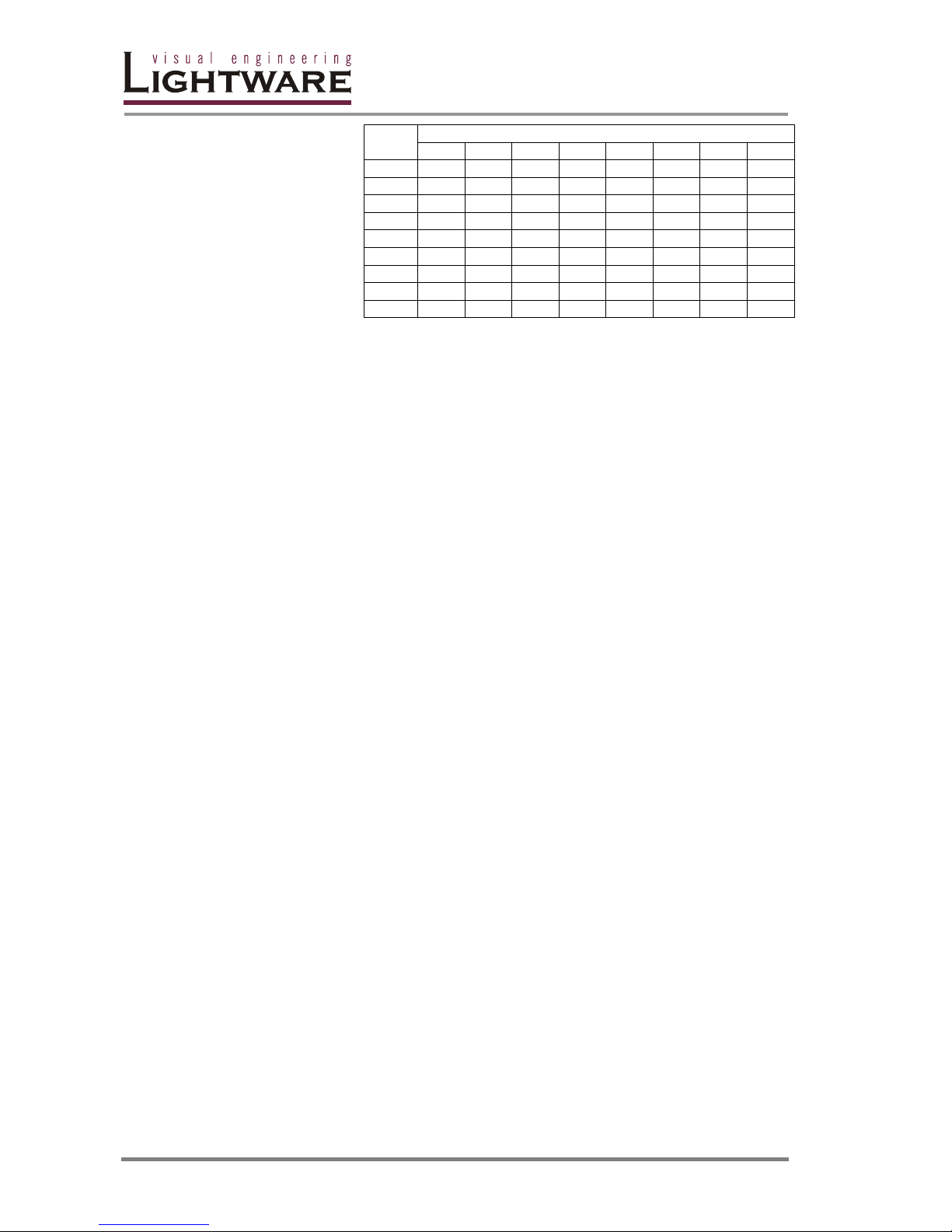
Page 60 / 109
f
f
value
Channel number
8 7 6 5 4 3 2 1
17
FRC FLC FC LFE FR FL
18
FRC FLC RC FR FL
19
FRC FLC RC LFE FR FL
1A
FRC FLC RC FC FR FL
1B
FRC FLC RC FC LFE FR FL
1C
FRC FLC RR RL FR FL
1D
FRC FLC RR RL LFE FR FL
1E
FRC FLC RR RL FC FR FL
1F
FRC FLC RR RL FC LFE FR FL
Legend:
FR / FL Front Right / Front Left
LFE Low-frequency effect
FC/RC Front Center / Rear Center
RR/RL Rear Right / Rear Left
FRC/FLC Front Right Center / Front Left Center
RRC/RLC Rear Right Center / Rear Left Center
Please note that the values of c, d, ee and ff fields are based on the
audio InfoFrame sent by the source device while values of a, b are
based on measurements. Of course audio InfoFrames are forwarded in
unchanged form to the HDMI sink devices (e.g. A/V Receivers) so that
they would be able to interpret the InfoFrames correctly.
Example: A1C010600; (two channel 48kHz PCM)
Note: This block is present only if an HDMI signal is available on the
selected port.
4.5.5.4. Advanced info block
Format: Iabcdef
For advanced users this block provides information which could be
useful during debugging process. The first character of this block must
be ’I’. The meanings of the following characters are:
a: 0 - VSYNC polarity is negative (leading edge falls)
1 - VSYNC polarity is positive (leading edge rises)
b: 0 - HSYNC polarity is negative (leading edge falls)
1 - HSYNC polarity is positive (leading edge rises)
c: 0 - There is no change on the TMDS clock line
1 - Signal is present on the TMDS clock line
d: 0 - The clock signal is unstable on the TMDS clock line
1 - The clock signal is stable on the TMDS clock line
Page 61

MX32x32DVI-HDCP-Pro and HDMI-Pro
User’s Manual v1.0
Page 61/ 109
e: Active Format Aspect Ratio based on AVI InfoFrame
0 Field is not present (e.g. DVI signal)
2 16:9 (top)
3 14:9 (top)
4 greater than 16:9 (centre)
5 Same as picture aspect ratio
9 4:3 (centre)
A 16:9 (centre)
B 14:9 (centre)
D 4:3 (with shoot and protect 14:9 centre)
E 16:9 (with shoot and protect 14:9 centre)
F 16:9 (with shoot and protect 4:3 centre)
f: Pixel repetition factor based on AVI InfoFrame
0 No repetition (i.e. pixel sent once)
1 Pixel sent 2 times (i.e. repeated once)
3 Pixel sent 4 times
Example: I111190;
(positive HSYNC and VSYNC, stable pixel clock, 4:3 aspect
ratio and no pixel repetition)
4.5.5.5. Input settings block
Format: Pab;
You are able to verify the actual settings on the selected input ports with
this block. This block is always present. The first character is ’P’, the
next characters are:
a: The cable equalization level at this input. The possible values
are:
0 Automatic cable equalization
1 Equalization is 3dB
2 Equalization is 9dB
3 Equalization is 25dB
4 Equalization is 35dB
5 Equalization is 40dB
b: The state of color range compression. The values are the
same as described in the 4.5.7 section.
Example: PAA;
(Automatic cable equalization and color range conversion is disabled)
Page 62
Page 62 / 109
4.5.6. Get detailed information about a HDMI output port
Supported cards MX-DVI-HDCP-OB
MX-HDMI-OB
Description: This command gets
more detailed information about an
output HDMI port. The response
will contain information about the
general signal parameters, the video resolution and mode, the audio format, other
advanced parameters, the capabilities of the sink device and the actual settings of
this port.
The main structure is the same as described at the HDMIIGET command in section
4.5.5. The STO response may have Video Info block, Audio Info block and
Advanced Info block with the same syntax as described in sections 4.5.5.2, 4.5.5.3
and 4.5.5.4 but there are also several new block types.
Example: → {:HDMIIGET12}
← (STO8=G11111;V1280x720p60,450,0;A1C05000b;
I1111IA;M11011107;OAAAAAU;)CrLf
The exact meanings of the new blocks are explained in the following sections.
4.5.6.1. General Info Block
Format: Gabcde;
This block provides information about the general status of the selected
HDMI output port. The first character is ’G’, the following characters have
different meanings:
a: 0 There is no attached sink device
1 Attached sink device is present (termination is present)
b: 0 DVI signal is transmitted
1 HDMI signal is transmitted (no deep color)
2 30 bits/pixel deep color HDMI signal is transmitted
3 36 bits/pixel deep color HDMI signal is transmitted
c: 0 No valid signal is routed to this port
1 Valid video signal is present
d: 0 HDCP encryption is currently disabled on this port
1 HDCP encryption is active
e: 0 Hotplug detect signal is low
1 Hotplug detect signal is high
→ {:HDMIOGET<in>}
← (STO<in>=Block1;Block2;...;
Blockn;)CrLf
Page 63

MX32x32DVI-HDCP-Pro and HDMI-Pro
User’s Manual v1.0
Page 63/ 109
4.5.6.2. Sink device Info Block
Format: Mabcdefggh;
This block provides some general information about the attached sink
device based on the EDID and the HDCP cypher engine. Please note
that you are able to get much more detailed information by downloading
the full EDID structure with the ,,we” command.
The first character of this block is ’M’, the meanings of the following fields
are described below.
a: 0 Sink device doesn’t support HDMI
1 Sink device is HDMI compatible
b: 0 HDCP authentication failed
1 HDCP authentication is successful
c: 0 Sink device is not an HDCP repeater
1 Sink device is an HDCP repeater
d: 0 Sink device doesn’t support YUV444 color space
1 Sink device supports YUV444 color space
e: 0 Sink device doesn’t support YUV422 color space
1 Sink device supports YUV422 color space
f: 0 Sink device has no audio capabilities
1 Sink device has audio capabilities
gg: This field represents a byte in hexadecimal format.
The meanings of the bits are:
data bit 0 - Sink device supports 32kHz PCM audio
data bit 1 - Sink device supports 44kHz PCM audio
data bit 2 - Sink device supports 48kHz PCM audio
data bit 3 - Sink device supports 88kHz PCM audio
data bit 4 - Sink device supports 96kHz PCM audio
data bit 5 - Sink device supports 176kHz PCM audio
data bit 6 - Sink device supports 192kHz PCM audio
data bit 7 - Reserved (Always 0 in this version of protocol)
h: One digit number, the meanings of the bits are:
data bit 2 - HDMI deep color 30bits/pixel mode is supported
data bit 1 - HDMI deep color 36bits/pixel mode is supported
data bit 0 - YUV444 color space is supported in DC modes
Info: Field c value is accurate only if the field b is equal to ’1’.
Example: M110111077;
Legend: HDMI and HDCP capable device, not HDCP repeater, it
supports all color spaces and 32kHz, 44kHz and 48kHz
PCM audio. All deep color modes are supported.
Additional audio formats may be stored in the EDID.
Page 64
Page 64 / 109
4.5.6.3. Output settings block
Format: Oabcdef
This block contains information about the actual settings of the selected
HDMI output port. The first character of the block is ’O’, the meanings of
the a,b,c,d,e fields are the same as the parameters of HDMIOSET
command described in section 4.5.8.
Example: OAACA1;
4.5.7. Set color range conversion at a HDMI input port
Supported cards MX-DVI-HDCP-IB
MX-HDMI-IB
MX-HDMI-TP-IB
Description: You are able to control
the color range conversion with this
command on the input ports. There are
three options: leave the color range
unchanged, compress or expand.
The first version of the command (@SI)
will affect only one port while the
second (@AI) makes changes on all
inputs. However the <in> field has no
significance in that case, it must be valid.
The possible values of the field a are:
A - No color range conversion
C - Compress the color range (0-255 16-235)
E - Expand the color range (16-235 0-255)
After the successful execution the system is going to respond with an STI response
with an included Input settings info block – so you are able to verify the new
settings.
Example: → {:HDMISET#6@SI=E}
← (STI6=S0000;PAE;) CrLf
4.5.8. Set HDMI output port parameters
Description: HDMI output cards
have various settings, which can be
set with this command. Every setting
has an automatic mode (this is the
default) when the system selects the
proper conversions based on the type
of the video signal and the
capabilities of the sink device, but
you are also able to force other
conversions with this command.
If you send the first version of the command (with @SO) then the new settings will
affect only the <out> output port. The @AO version will affect all HDMI output ports
regardless of the value of the <out> field.
→ {:HDMISET#<in>@AI=a}
←
(STI<in>=Block1;Block2;...;
Blockn;)CrLf
→ {:HDMISET#<in>@SI=a}
← (STI<in>=Block1;Block2;...;
Blockn;)CrLf
→ {:HDMISET#<out>@SO=a;b;c;d;e;}
←
(STO<out>=Block1;Block2;...;
Blockn;)CrLf
→ {:HDMISET#<out>@AO=a;b;c;d;e;}
←
(STO<out>=Block1;Block2;...;
Blockn;)CrLf
Page 65

MX32x32DVI-HDCP-Pro and HDMI-Pro
User’s Manual v1.0
Page 65/ 109
The possible values of the fields are:
a: A The HDMI/DVI mode selection is automatic.
D Always send DVI signal
H Force 24bits/pixel HDMI signal
1 Force 30bits/pixel HDMI deep color signal
2 Force 36bits/pixel HDMI deep color signal
x Don't modify this setting
b: A Automatic color space selection
1 Force RGB
2 Force YUV444
3 Force YUV422
x Don't modify this setting
c: A Handle color range conversion automatically
C Compress the incoming color range to 16-235
E Expand the incoming color range to full scale
x Don't modify this setting
d: A Automatic PCM subsampling
D Disable PCM subsampling
2 2x PCM subsampling (it only affects 2ch PCM signals!)
4 4x PCM subsampling (it only affects 2ch PCM signals!)
x Don't modify this setting
e: A Handle HDCP automatically
1 Always use HDCP
x Don't modify this setting
After the successful execution the system is going to respond with an STO
response with an included Output settings info block – so you are able to verify the
new settings.
Example: Force YUV444 24 bits/pixel HDMI signal on output port 4:
→ {:HDMISET#4@SO=H;2;x;x;x;}
← (STO4=G1100;OH2AAA;) CrLf
Example: Reset all settings to the factory defaults on output port 2:
→ {:HDMISET#2@AO=A;A;A;A;A;}
← (STO3=G1100;OAAAAA;) CrLf
Example: Reset the color space conversion to the default values on all output
ports:
→ {:HDMISET#7@AO=x;A;x;x;x;}
← (STO7=G1100;OAAAAA;) CrLf
Page 66
Page 66 / 109
4.5.9. Reset HDCP cache
Description: The matrix stores the so-
called KSV identifiers of the last sixteen
attached sinks and reports them to all
HDCP sources. This method eliminates the need of reauthentication on every
switching but it also has some side effects: if a source device doesn’t support 16
sinks at the same time, then it won’t work even after removing some display
devices.
By performing an HDCP reset you have the possibility of overcoming this problem.
The command will cause a short blinking period on all HDCP signals.
Example: → {:HDCPRESET}
← (OK) CrLf
4.5.10. Measure timing parameters
Description: The system continuously
measures the parameters of the
incoming signals such as pixel clock
frequency, horizontal and vertical back
porch, front porch etc. You are able to read this information from the matrix with
this command. This could be useful only for advanced debugging processes. To
get the active video resolution and common video parameters please use the
HDMIIGET command as explained in chapter 4.5.5.
This section assumes that you are familiar with the DVI standard and the computer
science.
The {:TIMINGS<in>} command will request the detailed timings information on the
input port <in>. The port number shall not be padded with zeros.
The answer repeats the command and consists of 15 data bytes. Every data byte
is represented as a two-digit hexadecimal number. The meanings of these data
bytes are:
data bytes
Description
1 Measured interval between two HSYNC active edges. The unit of the
value is unique pixels. MSB byte is first.
2
3 Measured interval between two VSYNC active edges. The unit of the
value is lines. MSB byte is first.
4
5 Defines the width of the active display area. The unit of the value is
unique pixels. MSB byte is first.
6
7 Defines the height of the active display area. The unit of the value is
unique pixels. MSB byte is first.
8
9 VSYNC to active video lines. This is equal to vertical sync width plus
vertical back porch. The unit of the value is lines.
10 Vertical sync front porch time measured in lines.
11 Reserved for future use
12 Width of the HSYNC pulse in units of unique pixels. LSB byte is first.
13
14 V value. This number is used to determine the actual pixel clock
frequency. MSB byte is first.
15
Use the following formula to calculate the actual pixel clock frequency:
f
pixelclock
= 58003,46 / V
→
{:HDCPRESET}
←
(OK)CrLf
→ {:TIMINGS<in>}
←
(TIMINGS<in>=[hexadecimal data
bytes])CrLf
Page 67
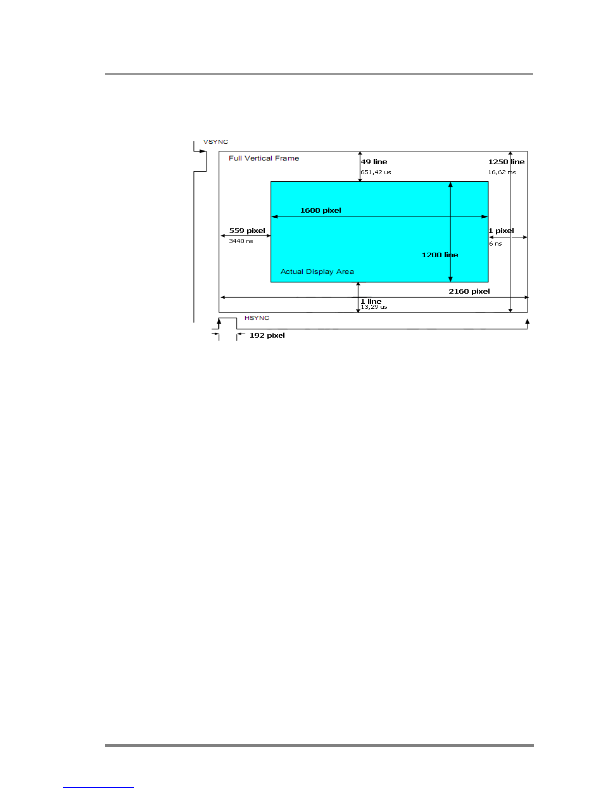
MX32x32DVI-HDCP-Pro and HDMI-Pro
User’s Manual v1.0
Page 67/ 109
Example: → {:TIMINGS8}
←(:TIMINGS8=087004e2064004b031010100c00165) CrLf
The explanation of this answer:
The pixel clock is 162,4 Mhz.
Note: Pixel clock is not equal to TMDS clock in deep color modes. To calculate the
TMDS clock you have to determine the number of bits per pixel (bpp) by running
an HDMIIGET command. The TMDS clock is equal to pixel clock multiplied by
bpp/24
If you want to evaluate the data rate or the needed bandwidth, you have to
calculate with TMDS clock.
Page 68
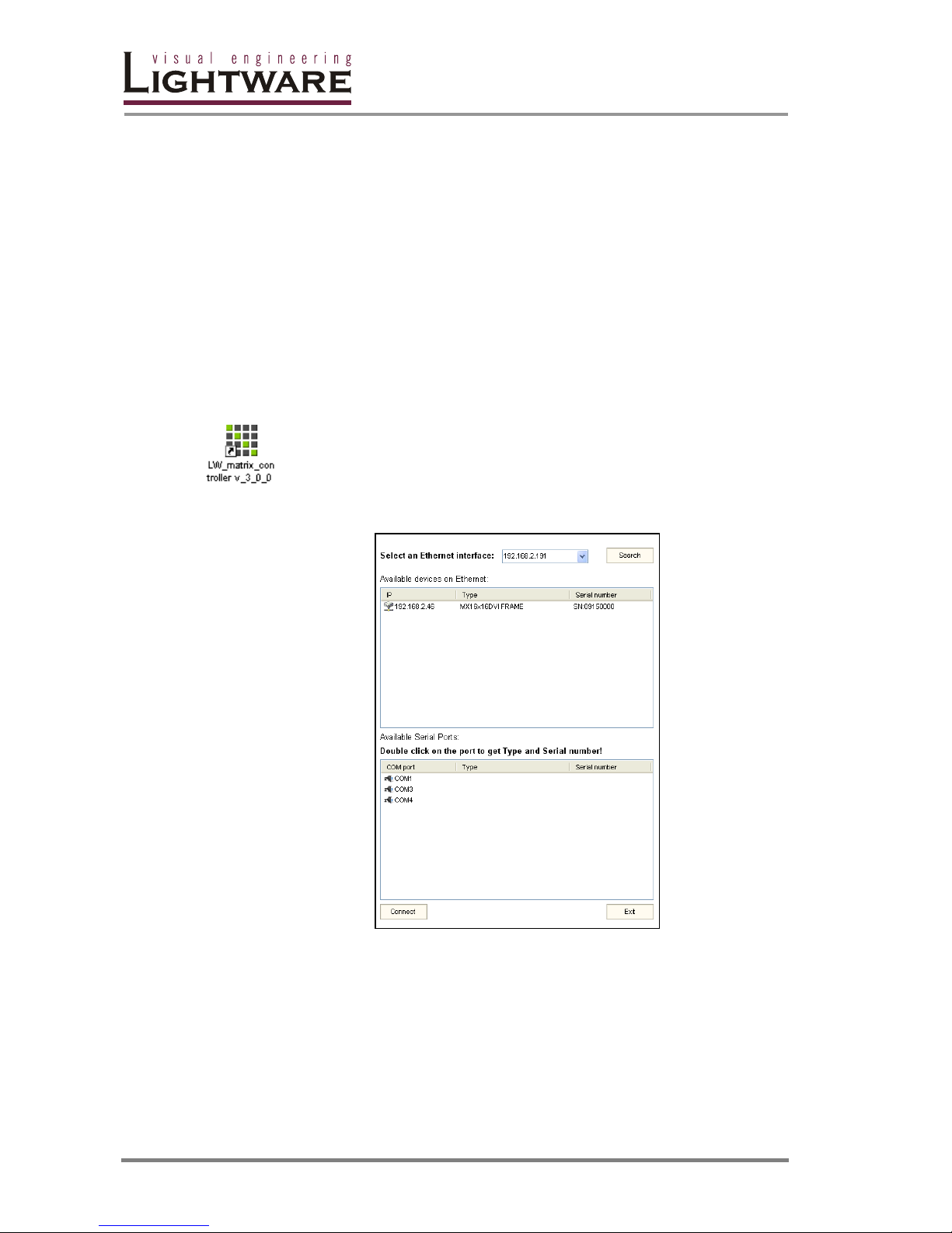
Page 68 / 109
5. Software control –Using Lightware Matrix Controller
5.1. Establishing the connection
The unit can be controlled using Lightware Matrix Controller software from a PC or
Laptop via RS-232 connection or Ethernet port.
Step 1. Connection between the Matrix and the computer can be made via
− serial port, with standard RS-232 Male to Female cable
− Ethernet (with a HUB or to a simple endpoint)
− Ethernet directly (with cross UTP cable)
Step 2. Starting the application
To run the CONTROL SOFTWARE double click on the icon of the software on
the desktop or select proper shortcut from Start Menu/Programs/Lightware
folder.
Step 3. Select communication interface according to your actual connection:
If the PC has more Ethernet cards installed, you can select the desired card to
query the LAN for Lightware devices.
If the connection has been made via ethernet select the desired IP address in the
window. No IP addresses will be shown if no LAN enabled Lightware matrix
switcher is connected to the same network that the PC is connected to.
If the connection has been made via serial port, select the appropriate
communication port. To query the selected COM port for the device Type and
Serial Number double click on then desired COM port.
Page 69
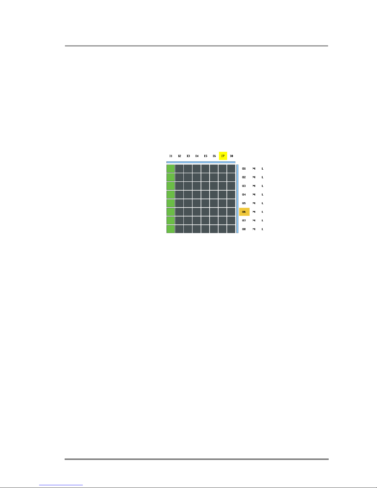
MX32x32DVI-HDCP-Pro and HDMI-Pro
User’s Manual v1.0
Page 69/ 109
Info: After starting the Lightware Matrix Controller, it automatically searches for
Lightware devices connected to the LAN. If it finds any, it picks its IP address, Type
and Serial Number and lists the devices. If there is not any matrix switcher
connected to the ethernet network, only serial ports will be shown in this menu.
Info: Only one user is allowed to connect to the matrix switcher via ethernet.
Info: Be sure that the firewall is not blocking the application!
Click on the Connect button to connect to the device. When the Lightware Matrix
Controller finds the hardware, it determines the product type, and a button matrix
area appears according to the input and output numbers of the router. I1; I2;
I3...columns represent the inputs, the O1; O2; O3...rows represent the outputs.
Each green square represents a valid connection.
5.2. Control menu
This menu contains the crosspoint area and the preset area. After connecting to a
new device, this menu appears by default.
5.2.1. Switch, mute and lock
For making a connection click on the desired square. If the output port is not locked
or muted, the connection will be made. Please note that if an HDCP encrypted
signal is switched to a non-HDCP sink then a blank red picture will be sent.
For switching an input to all outputs, click with the left mouse button on the input
label, and click “Switch to all outputs” from the popup menu.
Outputs can be easily muted by clicking on the button titled ’M’ beside the output.
This means that no signal is present at this output.
Outputs can be locked to any input. After locking an input to an output, no
switching is permitted to this output unless it is unlocked again.
Info: Loading a preset doesn’t alter either the lock state or the switch state of a locked
output. If an output is locked to an input before preset loading it will also be locked
to that input after preset loading, so locked outputs ignore the preset.
Page 70
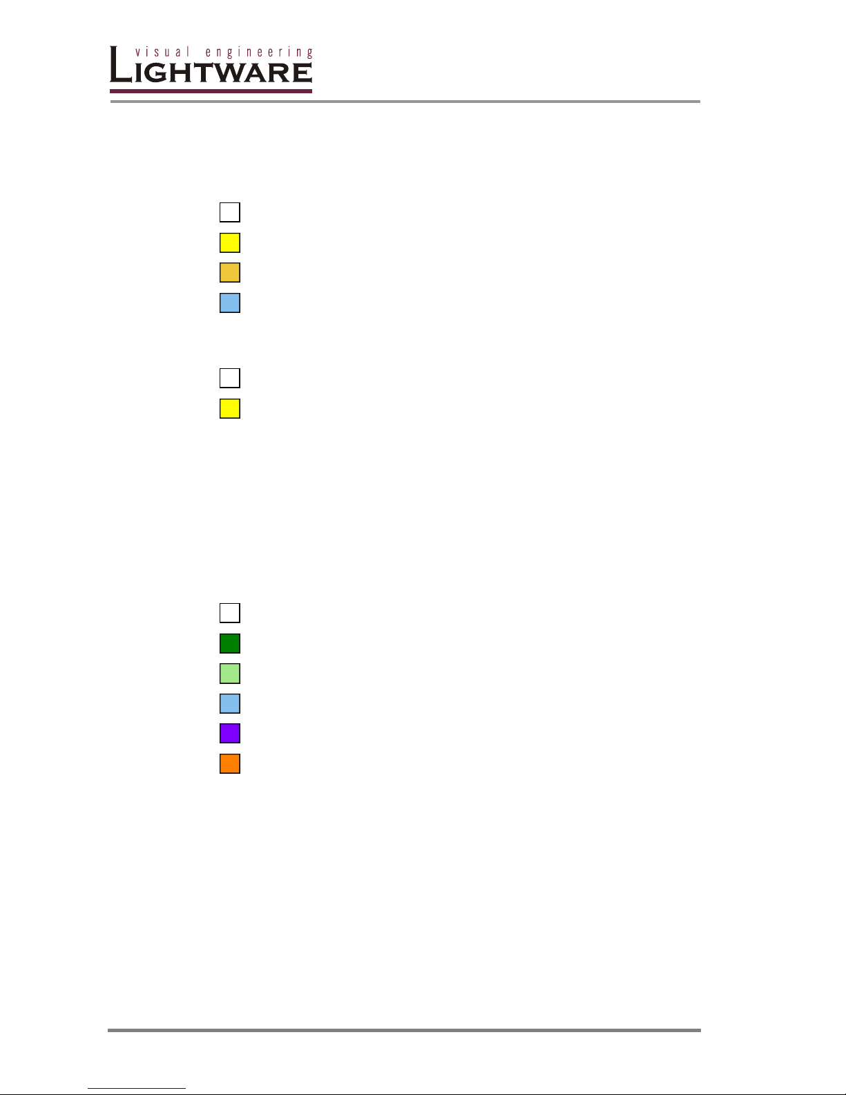
Page 70 / 109
5.2.2. Input and output states
Each input and output label has a colored background according to its state, so the
user can see the main information with a quick look at them.
Legend for input labels:
No source is connected. The power +5V is not present.
Source is connected, but there is no active video signal.
DVI signal is present on the link.
HDMI signal is present on the link.
Legend for output labels:
There is no device connected or the connected device is turned off.
Hotplug is present, a sink is connected.
Staying with the cursor above a label shows a hint about these states.
5.2.3. Card types
With Lightware Hybrid Technology the matrix frames can be equipped with
different types of cards. The colored bars near the crosspoint area display the type
of the card in each slot. Whether it is an optical, a twisted pair or other kind of card,
a different color represents it’s type.
Legend for card types:
Unknown card or empty slot.
MX-DVID card
MX-DVI-TP card
MX-HDMI or MX-DVI-HDCP card
MX-DVI-DL card
MX-OPT-DVI card
Page 71
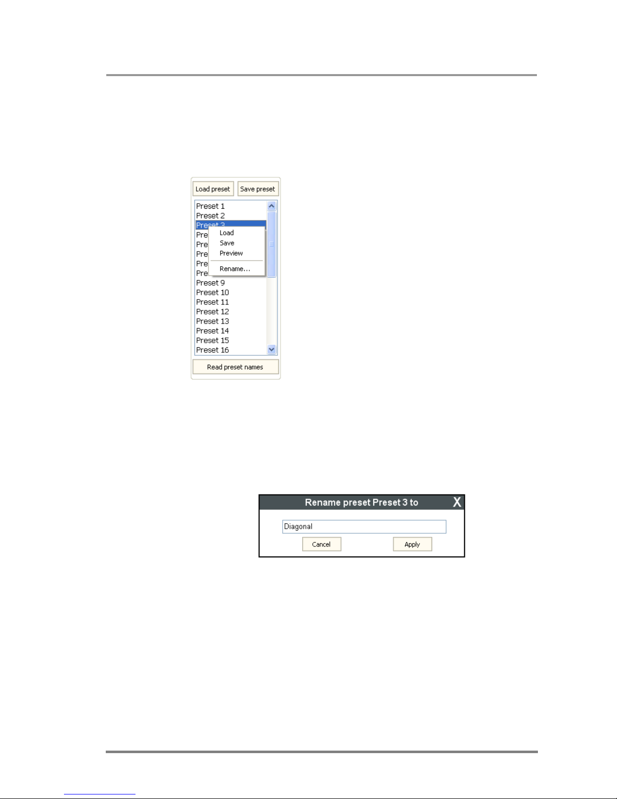
MX32x32DVI-HDCP-Pro and HDMI-Pro
User’s Manual v1.0
Page 71/ 109
5.2.4. PRESET operations
Preset operations can be done on the right PRESET panel. Each Lightware matrix
switcher has 32 preset memories that can be loaded and saved at any time.
Info: A preset setting stores a full configuration of all outputs, so presets have an effect
on every output, when loading a Preset.
Load preset
Step 1. Select the preset memory (Preset1...Preset32)
you want to load as the next configuration.
Step 2. Press LOAD PRESET button or right click on
Load in the popup menu. Now the preset is loaded.
Step 3. The new I/O configuration is displayed on the
matrix switching area.
Save preset
Step 1. Make the desired configuration on the matrix
switching area.
Step 2. Select the preset memory (Preset1...Preset32)
where you want to save your current configuration.
Step 3. Press SAVE PRESET button or right click on the
preset and click Save in the popup menu. Now the preset
is stored.
Rename preset
Step 1. Select the preset memory (Preset1...Preset32) you want to rename.
Step 2. Right click RENAME... in the popup menu. The Rename window appears.
Step 3.Type in the desired name and click APPLY. Now the new preset name is
stored.
Info: If the CPU firmware version is above 2.0.0 then the preset names are stored in the
matrix memory and they can be loaded in another PC. Otherwise, the preset
names are stored locally in a file on the current PC.
Read preset names
Click on the READ PRESET NAMES button in the preset area to download them
from the device. The control software doesn’t download the names automatically, if
you want see the names stored in the matrix, you have to click this button
manually.
Page 72
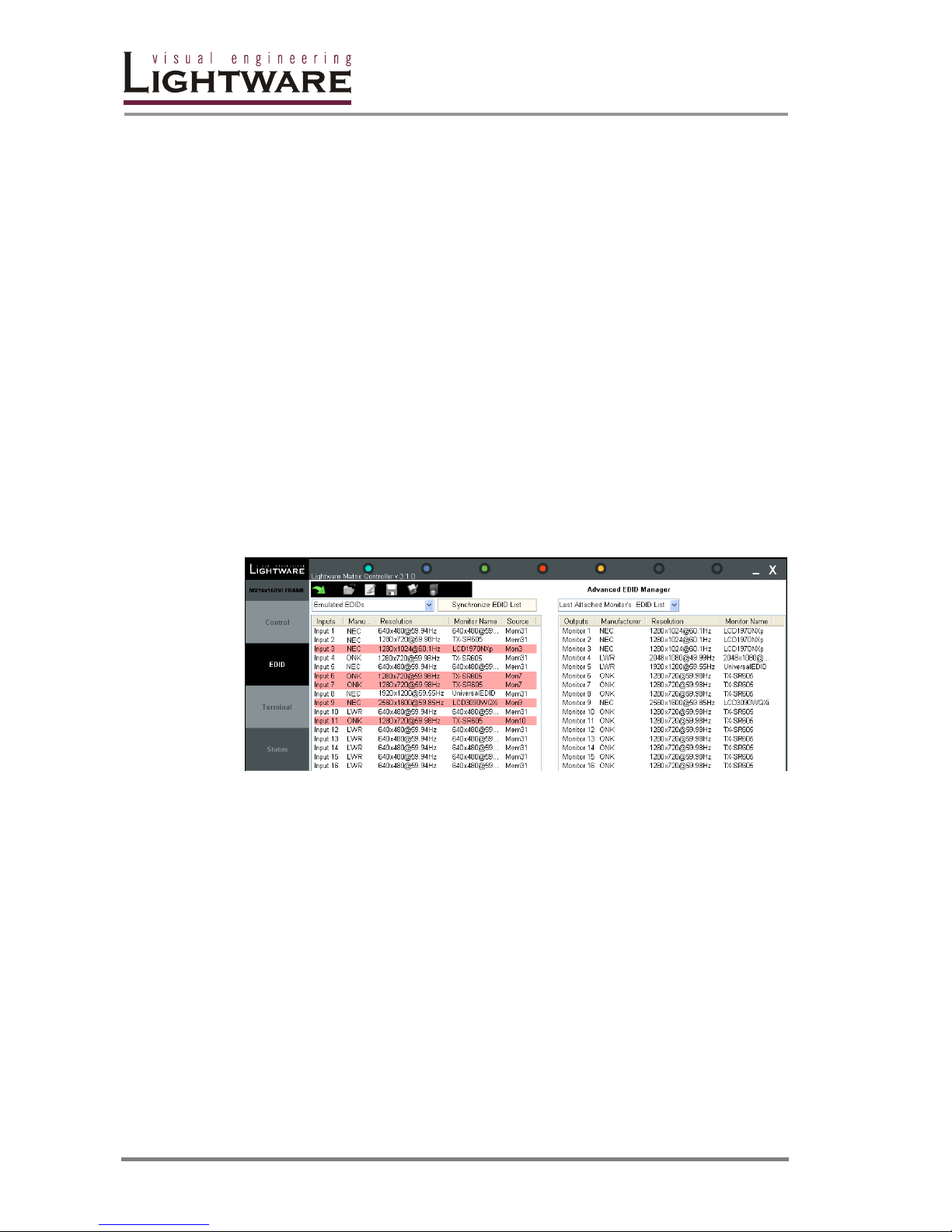
Page 72 / 109
5.3. EDID menu
5.3.1. EDID Router operation
By clicking on the EDID menu, the EDID router window appears.
When the user enters the menu for the first time, the software starts to download
the whole EDID list from the matrix. It may take about 30-40 seconds.
After the list is downloaded, the current status of the EDID list is shown in two
windows. In the combo box you can select which part of the EDID memory to be
seen in which window.
The Emulated EDID List window contains the resolution, manufacturer and vendor
name of the EDID reported to the sources for each input separately. The source
column displays the memory location that the current EDID was routed from. The
rows with red background are dynamically routed to the input.
The Last attached Monitor's EDID List window contains the resolution,
manufacturer and vendor name of the display devices connected to matrix
switcher's output.
The Factory EDID List window shows the factory memory locations with
preprogrammed EDID.
The User EDID List shows the memory locations which can be used by the user to
save EDID.
Change emulated EDID at one or all inputs
All EDID are enumerated in the left and the right lists too. The two main types of
the emulation are the static and the dynamic:
- Static EDID emulation happens, when an EDID from memories 1..100 is selected
and emulated at the input(s)
- Dynamic EDID emulation occurs, when an attached monitor’s EDID is emulated
at input(s), simply copying the data from the monitor. This EDID changes
automatically, if a new monitor is attached to the output.
Step 1. Select the Emulated EDID List in one of the list window areas in the dropdown menu.
Step 2. Select the desired EDID from one of the list windows (from #1..100 through
Input1..to Output32)
Step 3. Drag and drop the EDID to the desired location.
To change the emulated EDID on all inputs at the same time, right click on the
desired new EDID and select “Switch to all Inputs” from the pop-up menu.
Page 73

MX32x32DVI-HDCP-Pro and HDMI-Pro
User’s Manual v1.0
Page 73/ 109
Info: If a monitor’s EDID was selected to be emulated (Output 1 to 8) the currently
emulated EDID will be changed on that(those) input(s) every time a new monitor is
connected. If the monitor is disconnected from the output, the latest EDID remains,
it will not be deleted from the input. This feature helps especially rental technicians
or system integrators to keep the source continuously transmitting the signal, and
adopt the system for new incoming display devices.
Info: Power ON/OFF cycle will not affect the emulated EDID or other settings.
Info: EDID switch procedure causes a status change and hence it is reported back to
the CONTROL SOFTWARE within 2-3 seconds.
Learn EDID from attached display device
The system is able to learn the EDID from the connected display device and store
it in one of the user programmable memory locations.
Step 1. Select the User Memory in one of the list window areas in the drop-down
menu.
Step 2. Select the EDID to be saved from the other list window.
Step 3. Drag and drop the selected EDID to the desired User Memory location.
Load EDID from file to memory
The system is able to learn and store EDID from a file located on the computer.
EDID are stored in *.dat files.
Step 1. Select the User Memory list window from one of the combo boxes, and
right click on the desired memory location. Then select “Load from file” from the
pop-up menu.
Step 2. Browse your hard drive to find the wanted EDID file in the pop-up window.
The software checks whether the selected file is a valid EDID file.
Step 3. Click Open in the browser window. After the process finished, ”EDID
Upload completed” message appears.
Save EDID from memory to file
The control software is able to download EDID from the MATRIX SWITCHER and
to save it as an EDID file.
Step 1. Right click on the EDID to be saved.
Step 2. Click on the “Save to file” in the pop-up window.
Step 3. The Matrix Controller Software downloads the desired EDID and a save
dialog appears. It may take a few seconds to download the EDID. If the save dialog
is shown, type in the file name, and press Save button. After the process was
completed, an ”EDID saved!” message confirms the command.
Synchronize EDID
By clicking “Synchronize EDID List” button the Lightware Matrix Controller software
rereads all EDID information from the connected MATRIX SWITCHER. During
normal operation it is not necessary to use this menu function because the matrix
switcher always reports every status change automatically.
Info: There is always a small delay in responses. So if a new monitor is connected to the
output its new EDID is not shown immediately but in 2-3 seconds!
Page 74
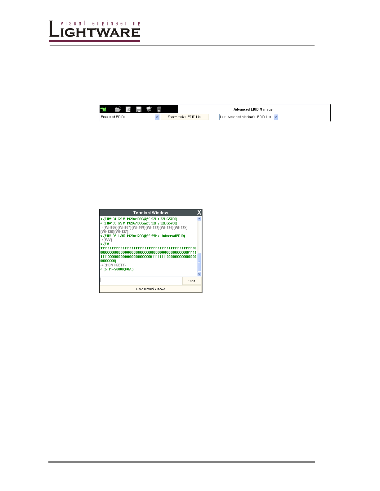
Page 74 / 109
Info: As the matrix switcher reports status change nothing will happen if you select the
same EDID to a given input or connect the same display device to a given output!
5.3.2. Advanced EDID Manager
The Lightware Advanced EDID Manager is integrated into the Lightware Matrix
Controller software. By clicking on the green arrow, the editor area rolls down.
When the user enters the menu first, an empty EDID is loaded into the editor’s
memory.
All EDID in the matrix memory can be edited in the following way:
Step 1. Right click on the desired EDID to be loaded to the EDID Manager.
Step 2. In the pop-up menu, click on “Edit EDID” The editor area automatically rolls
down, and the EDID is loaded into the editor area.
5.4. Terminal menu
This general-purpose serial terminal is
intended mainly for test and debug
purposes. After a successful connection
to a router this terminal can be used
either via serial or TCP/IP connection. All
commands can be used here that were
discussed in the Programmer’s
reference section. The text can be typed
directly.
By default commands are surrounded by
framing brackets. Every sent command
and every received response gets an
arrow (-> or <-) prefix, and has different
font colors in order to help distinguishing.
5.5. STATUS menu
Basic device information, the installed cards’ firmware, hardware revisions and the
router’s health are displayed in this window.
Page 75
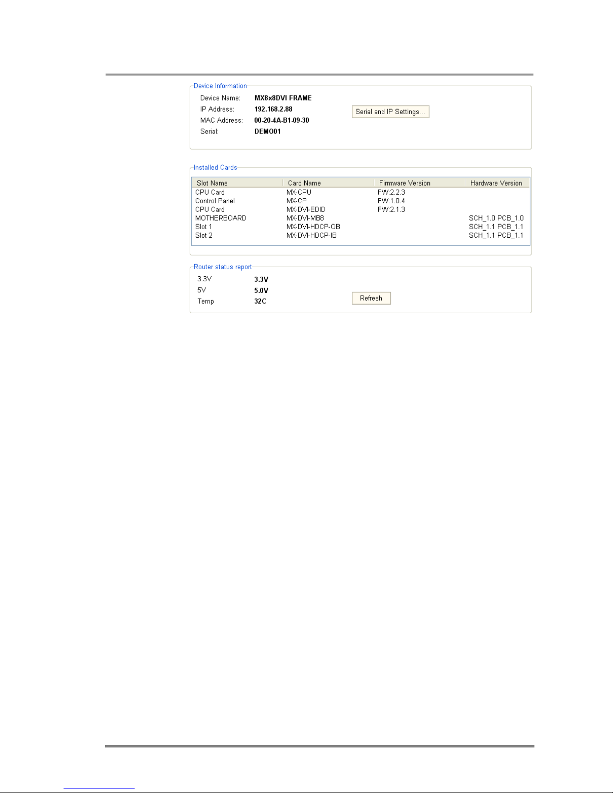
MX32x32DVI-HDCP-Pro and HDMI-Pro
User’s Manual v1.0
Page 75/ 109
Info: If the device is connected via RS-232, the IP and MAC address fields show that it
is a serial connection.
If the matrix is connected via IP connection, the serial and IP settings can be
viewed by clicking on the “Serial and IP Settings...” button. Now the window
containing the configuration appears.
5.5.1. IP configuration
Obtain IP address automatically
By selecting the “Obtain IP address automatically” option, the matrix gets the IP
address from the DHCP server on the LAN, or if DHCP server is not present, it gets
an AutoIP address from the 169.254.xxx.xxx domain.
Fix IP configuration
In this case, the matrix has an IP address configuration set up by the
user/administrator.
Step1: Select the “Fix IP configuration” option.
Step 2: Type in the IP address, select the desired subnet mask and type in the
gateway IP address. The current configuration is in brackets.
Step 3: Click on “Apply Settings” button. Depending on the modified settings, you
might need to restart the Matrix Switcher and the Matrix Controller Software.
Page 76
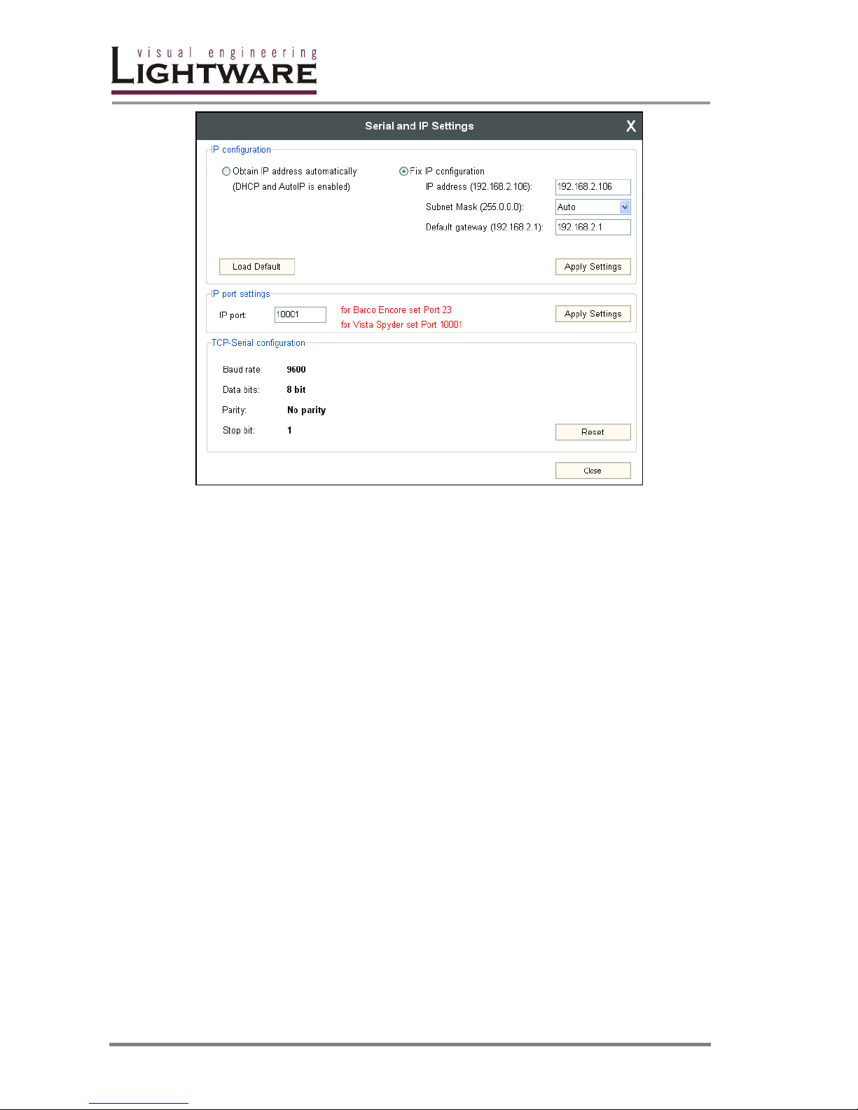
Page 76 / 109
Info: The “Load Default” button loads the factory default IP settings to the fields, which
contain a fix configuration:
IP Address: 192.168.254.254
Subnet Mask: 255.255.0.0
Default Gateway: 0.0.0.0
IP port settings
The router can be accessed via this TCP/IP port number with TCP connection. This
number can be modified to any number between 1025-65535 except the
followings: 9999, 14000-14009,30704,30718.
The port 23 is accepted for Barco Encore. To use the matrix with the Vista Spyder
set port to 10001.
Info: The IP port number is 10001 by default.
TCP-serial configuration
For informational purposes, the properties of the TCP-serial interface are
displayed. This is a communication interface from the embedded Ethernet device
towards the main CPU.
The “Reset” button resets these values to the factory default, and has a safety
purpose only.
In the normal operation there is no need to reset these values. The above picture
shows the factory default values in normal operation.
Page 77
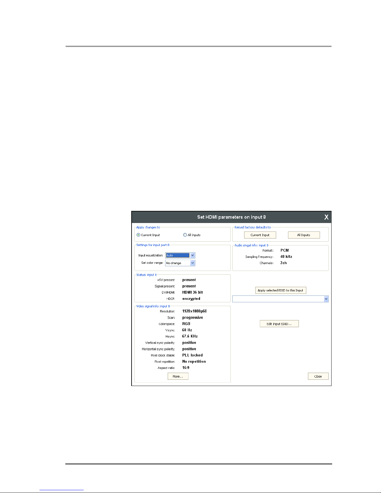
MX32x32DVI-HDCP-Pro and HDMI-Pro
User’s Manual v1.0
Page 77/ 109
5.6. Find menu
By clicking this menu, the available devices can be rescanned on the serial port
and on the Ethernet, as mentioned in the application starting phase. If the Matrix
Controller Software has a live connection to a device on a port, a question window
appears, asking if you really want to disconnect.
5.7. Input and output Settings
If the MATRIX SWITCHER has one or more input or output cards installed, that
have properties available for the user/system administrator to change, than the
settings window can be reached by right clicking on the input or output label. The
exact look of the setting windows may depend on the type of the card because the
different cards have different capabilities. The pictures below are about MX-DVIHDCP and MX-HDMI input and output cards.
5.7.1. Set HDMI parameters on input
A right click on input port label near the crosspoint field will result in opening the
HDMI setting window if the card is HDMI capable.
Apply changes to
Current input: this option means the modified parameters are applied only to
the currently selected port.
All inputs: this option means that the modified parameters are applied to all
input ports.
Info: After closing this window, the Current Input option will be selected regardless of
which was active at the time of closing. It is to avoid setting All Inputs by mistake.
Page 78

Page 78 / 109
Reload factory defaults
Current input: Loads the factory default values to the currently selected input.
All inputs: Loads the factory default values to all inputs.
Settings for input port
Input equalization: Each input port has a built-in equalizer, which is able to
compensate the attenuation of DVI and HDMI cables for up to 60 meters at
1080p60 resolution. These equalizers work in automatic gain control mode by
default and in most cases this operates with adequate result. Sometimes –
especially with very long cables – the equalization level has to be set manually.
Set color range: With this setting you are able to control the color range
conversion on the input ports. There are three options: leave the color range
unchanged, apply compression (0-255 16-235) or expansion (16-235 0-255).
Status
+5V present Shows if there is a source device connected to the port.
Signal present Shows if there is valid video signal on this input.
DVI/HDMI Shows the current mode and color depth.
HDCP Shows if the encryption is active or not.
Video signal info
Resolution Horizontal and vertical resolution, scan mode and the
refresh rate of the signal.
Scan Scan mode (interlaced or progressive).
Color space Shows the actual color space of the video signal (RGB,
YUV 4:4:4, YUV4:2:2).
Vsync Vertical refresh rate.
Hsync Frequency of the horizontal sync.
Vsync polarity The polarity of the vertical sync. It can be negative
(leading edge falls) or positive (leading edge rises).
Hsync polarity: The polarity of the horizontal sync. Polarity can be
negative (leading edge falls) or positive (leading edge
rises)
Pixel clock stable: Shows whether the clock signal is stable on TMDS line.
Pixel repetition: Pixel repetition factor (1x, 2x, 4x).
Aspect ratio: Active Format Aspect Ratio based on AVI InfoFrame
Audio signal info
Format Shows the type of the audio.
Sampling frequency Shows the sampling frequency determined by the built-in
audio clock regeneration unit.
Channels: Shows the channel number as extracted from the Audio
InfoFrame (0 to 7).
Page 79
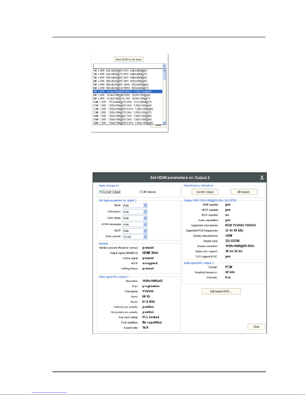
MX32x32DVI-HDCP-Pro and HDMI-Pro
User’s Manual v1.0
Page 79/ 109
EDID switching
A selected EDID can be switched to the
currently selected input directly from the
input settings window.
Step1: Go to the EDID menu, and query the
EDID list if it has not been downloaded from
the matrix switcher yet. (A notifying text can
be seen in this case) Now the switching from
the settings window is available.
Step 2: Select the desired EDID from the
drop-down list.
Step 3: Click on “Switch EDID to this Input”
button. Now the matrix switches the EDID,
and the software refreshes the list.
5.7.2. Set HDMI parameters on output
A right click on input port label near the crosspoint field will result in opening the
HDMI parameter setting window if the card is HDMI capable.
Apply changes to
Current output: this option means the modified parameters are applied only
to the currently selected port.
Page 80

Page 80 / 109
All outputs: this option means that the modified parameters are applied to all
output ports.
Info: After closing this window, the Current Output option will be selected regardless of
which was active at the time of closing. It is to avoid setting All Outputs by mistake.
Reload factory defaults
Current output: Reloads the default values to the currently selected output.
All outputs: Loads the factory default values to all outputs.
Set signal properties for output
Mode It specifies the desired type of outputted signal on the
port (Auto, DVI, HDMI 24-bit, HDMI 30-bit or HDMI 36bit).
If you select Auto, the system will configure the mode
automatically based on the capabilities of your display
and the incoming signal.
Color space Convert the color space on the output to the given type.
You are able to force any-to-any color space conversion
or leave this field on Auto. Please note that DVI signals
support only RGB color space.
Color range Defines color range conversion for the output port.
LPCM subsample Defines the subsampling of the PCM audio signal. This
setting applies only to the 2-channel PCM audio. The
minimum of the new sampling frequency is 44.1kHz.
HDCP Determines HDCP encryption for the output signal. In
automatic mode the encryption depends on the incoming
signal. You are also able to force HDCP on non protected
signals. Removing the encryption from a content
protected video is not possible due to the limitations of
the specification.
Drive current It specifies the drive current of the internal crosspoint
circuit. It is strongly recommended to leave this value at
the default 12mA.
General
Monitor present Shows if there is a sink device attached.
Output signal Actual type and color depth of the transmitted signal over
this port.
Active signal Shows if there is a valid signal routed to this output port.
HDCP Shows if the HDCP encryption is currently enabled or
disabled.
HotPlug Detect Shows if the sink device is ready to receive the signal.
Display
HDMI capable Shows whether the sink supports HDMI.
HDCP capable Shows if the HDCP authentication was successful or
failed.
HDCP repeater Shows if the sink device is an HDCP repeater or not.
Page 81

MX32x32DVI-HDCP-Pro and HDMI-Pro
User’s Manual v1.0
Page 81/ 109
Audio capabilities Shows if the sink device is able to receive audio.
Supported color spaces The supported color spaces by the sink device.
PCM frequencies List of the supported PCM audio sample rates.
Display manufacturer If there is a sink device attached, this field shows the
abbreviation of the device's manufacturer, as defined in
the device's EDID.
Display type If there is a sink device attached, this field shows the
device name given by the vendor, as defined in the
device's EDID.
Display resolution If there is a sink device attached, this field shows the
resolution of the device, as defined in the device's EDID.
Deep color support Shows whether the display supports the 30bpp and
36bpp deep color modes or not.
YUV support in DC If the display supports any deep color modes, this field
shows whether YUV 4:4:4 color space is supported while
using deep color formats or not.
The video signal info and audio signal info has the same fields as described in
section 5.7.1.
Page 82
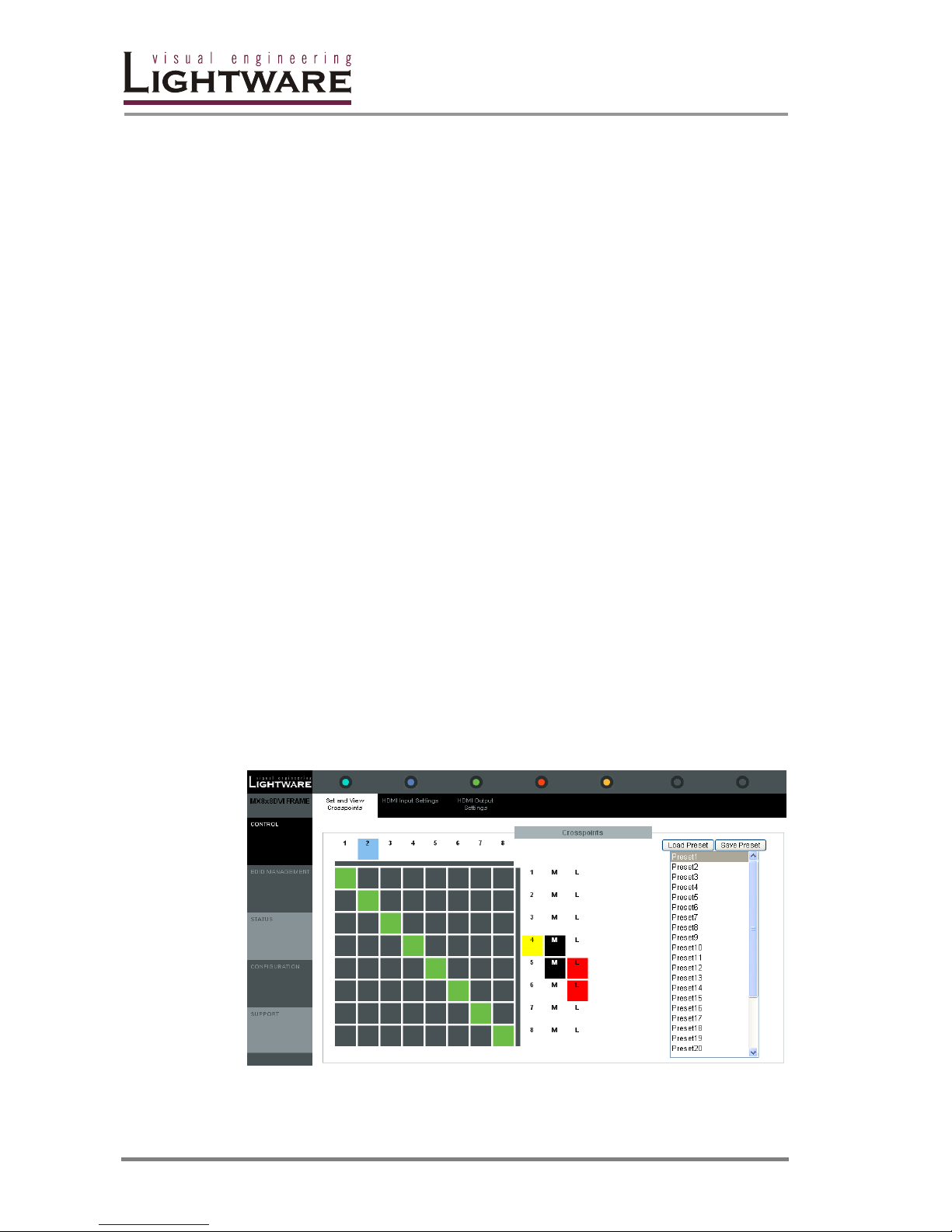
Page 82 / 109
6. Using the WEB interface
6.1. Accessing the router’s web page
Lightware matrices have a built-in web page, which can be accessed over TCP/IP
protocol and offers you full control over all settings even if you don’t have the
opportunity to install new programs. The router web is compatible with most widely
spread browsers and requires no additional software components such as ActiveX
controls. The web interface functionality has been tested and confirmed with the
following browsers:
Mozilla Firefox 2 and 3 (recommended)
Internet Explorer 6, 7 and 8
Opera 8 and 9
Safari 3
Google Chrome 2.0
Note: The web page is not compliant with Google Chrome 1.0.
To access the webpage just run your preferred web browser and type the IP
address of the router as URL.
Note: Only one opened web page is allowed simultaneously. Other TCP/IP connections
are prohibited while the web page is opened. Using more instances of the web
page simultaneously will result in inadequate operations.
6.2. Manage crosspoints and presets
After starting the web page, the crosspoints screen appears by default according to
the input and output numbers of the router. Columns represent the inputs while the
rows are the outputs. Each green square represents a valid connection. New
connections can be made by clicking on the desired gray square.
The labels of the inputs and outputs are colored depending on the port status. The
legend is the same as described in section 5.2.2 on page 70.
Page 83

MX32x32DVI-HDCP-Pro and HDMI-Pro
User’s Manual v1.0
Page 83/ 109
Mute
To mute or unmute an output, just click on the M label in the proper row. The
muted port will be marked with black background as shown in the picture above.
This means that no signal is present at this output.
Info: Switching is permitted during mute.
Lock
Outputs can be locked to any input. After locking an input to an output, no
switching is permitted to this output unless it is unlocked again.
Info: Loading a preset does not change either the lock state or the switch state of a
locked output. If an output is locked to an input before preset loading, it will also be
locked to that input after preset loading, so locked outputs ignore the preset.
Click on the proper L label to lock or unlock an output. If an output is locked then it
is marked with red and can’t be switched or muted before unlocking in order to
prevent accidental actions.
Preset operations
Preset operations can be done in the right panel of the Control->Set and View
Cross-points page. Each Lightware matrix switcher has 32 preset memories that
can be loaded and saved at any time.
Front panel Preset operations effect only the first 8 preset memories, all others
from 9 to 32 are available only via Matrix Controller software and Web Manager.
Save Preset
Step 1 Make the desired configuration on matrix switching area.
Step 2 Select the preset memory location (Preset1...Preset32)
where you want to save your configuration.
Step 3 Press Save Preset button. A message box appears
stating that the preset is now stored.
Load Preset
Step 1 Select the preset memory location (Preset1...Preset32)
you want to load as next configuration.
Step 2 Press Load Preset button. The preset is now loaded.
Step 3 The new I/O configuration is displayed in the matrix
switching area.
6.3. HDMI settings
When control menu is selected on the left side, HDMI Input and HDMI Output
settings submenus can be selected on the top of the page. These pages allow you
check the incoming and outgoing signal parameters and control the settings of the
ports independently.
Page 84
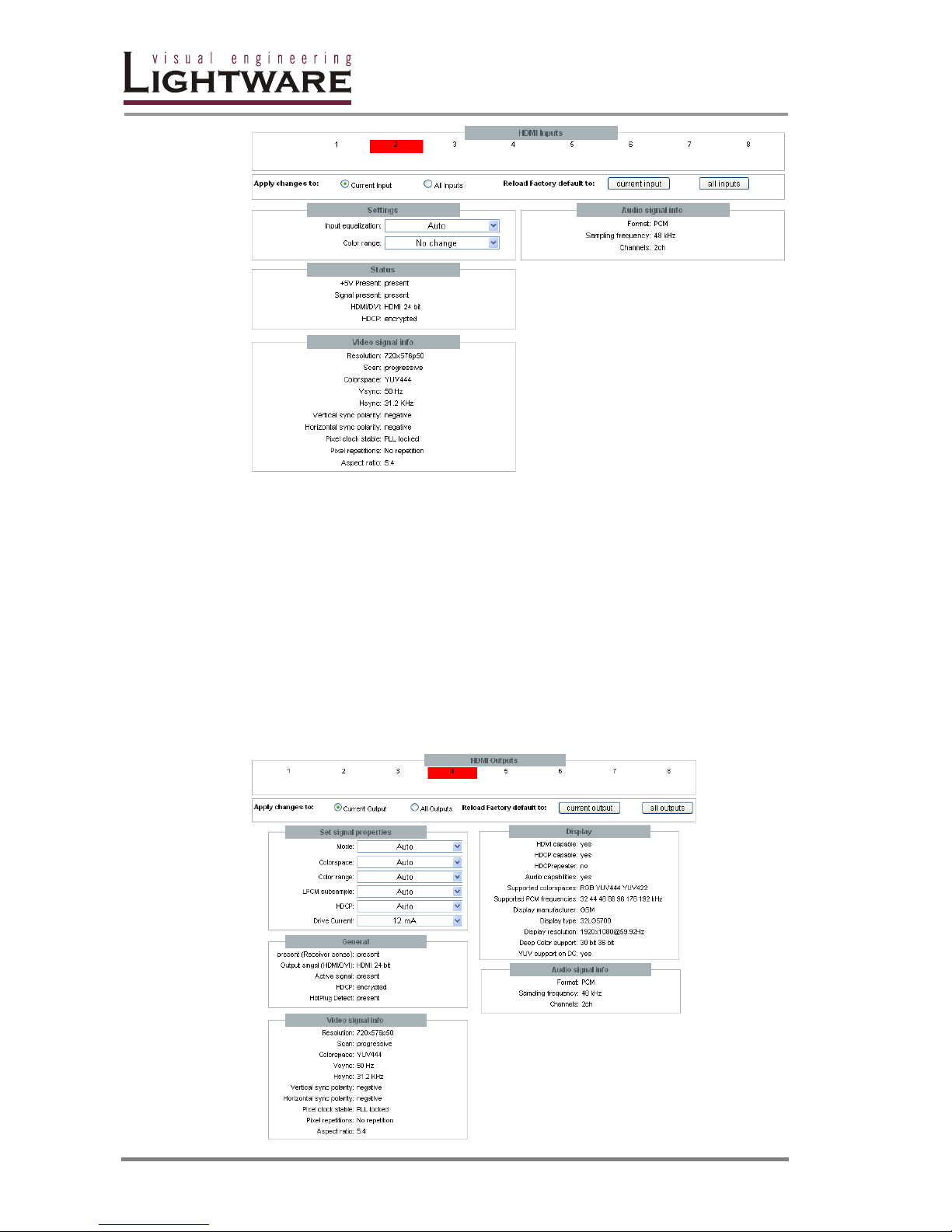
Page 84 / 109
The picture above shows the HDMI input settings. You are able to check and set
the same parameters here that are described in detail in section 5.7.1. The settings
can be applied to all inputs or to the selected input. The selection can be made on
the top; the selected input is marked red. You also have the opportunity to reload
the factory default settings to one or to all inputs.
If you made any changes in the “Settings” box, the new settings will have an effect
immediately.
By selecting HDMI Output settings, another screen appears (shown below). All
parameters can be accessed here that are described in section 5.7.2 including the
general port status, video and audio signal info and the capabilities of the attached
display device.
New settings and factory defaults can be applied either to all outputs or to one
output just like the input settings. The detailed description of each output setting
can be found on page 80.
Page 85
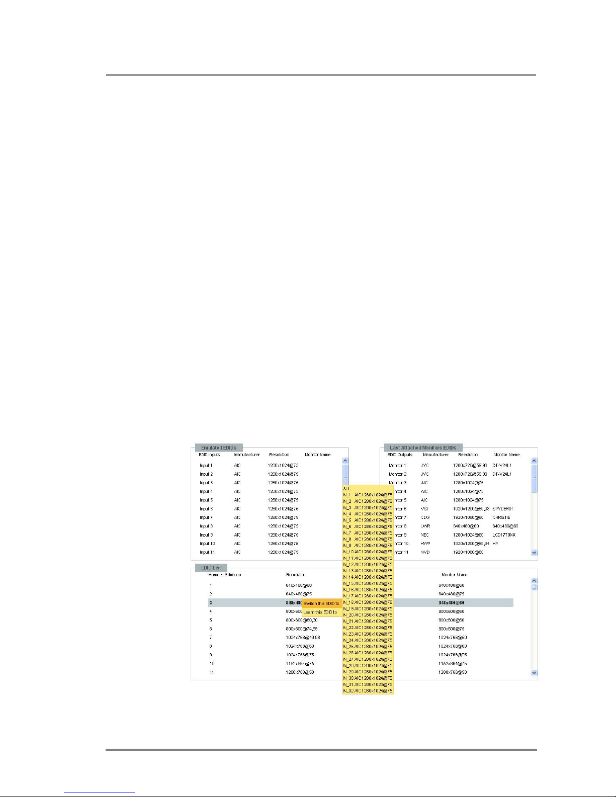
MX32x32DVI-HDCP-Pro and HDMI-Pro
User’s Manual v1.0
Page 85/ 109
6.4. EDID Router operation
By clicking on the EDID Management menu, the EDID router page appears.
When the user enters the menu for the first time, the Web Manager starts to
download the whole EDID list from the matrix. It may take 2 minutes.
After the list is downloaded, the current status of the MATRIX SWITCHER EDID is
shown in the three textboxes.
The Emulated EDIDs window contains the resolutions and the vendor names of
the EDID reported to the PC for each input separately. The Last attached
Monitor's EDIDs window contains the resolutions and vendor names of the display
devices connected to matrix switcher's output.
6.4.1. Change emulated EDID at one or all inputs
All EDIDs are enumerated in the EDID list window.
Step 1 Select the desired EDID from this list with a left mouse
click, a pop-up menu appears.
Step 2 Right click on the Switch this EDID to item. A pop-up
menu appears with an input name list.
Step 3 Right click on the desired input, or on the ALL text. Now
the EDID has been changed on selected input as the
message box shows in the left corner.
Info: Switching to ALL inputs may take several seconds.
Info: The user can switch and learn EDIDs in the Last Attached Monitors EDIDs
window.
Page 86
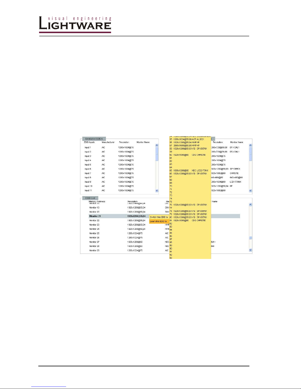
Page 86 / 109
6.4.2. Learn EDID from attached display device
The matrix switcher can learn the EDID from the connected display device and can
store it in one of the user programmable memoriy locations. Every monitor's EDID
is listed in the EDID list window, and in the Last Attached Monitors EDIDs
window.
Step 1 Right click on the desired monitor's EDID from the list.
Step 2 Right click on the Learn this EDID to submenu item. A
pop-up window will show the memory locations from 50
to 100, which are available for the user.
Step 3 Right click on the desired memory location. The Web
Manager refreshes the lists in a few seconds, and a
massage box indicates the change.
6.5. Status
Installed cards, the router's health, firmware and hardware versions are displayed
in this page.
With the Refresh button, the user can update the temperature, voltage, and fan
values.
Note: FAN values are not accessible in the MX8X8 frame.
Page 87
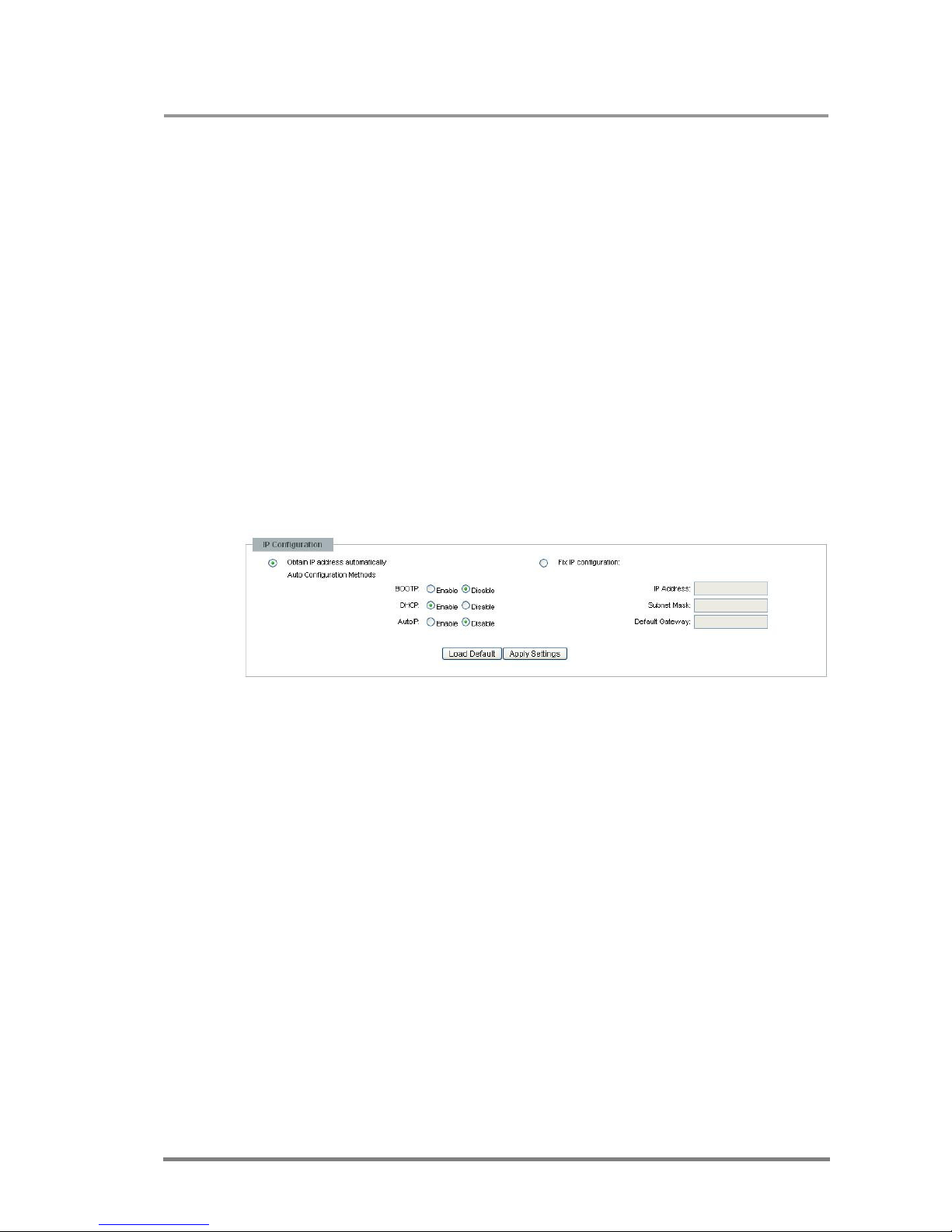
MX32x32DVI-HDCP-Pro and HDMI-Pro
User’s Manual v1.0
Page 87/ 109
6.6. Network Configuration
The unit's network values are displayed when you select Configuration->Network
Settings.
The following sections describe the configurable parameters on the Network
Settings page.
Info: Most of these settings are also available from the front panel. See page 34 for
more details.
6.6.1. Assign IP address automatically
The matrix switcher supports three of the most commonly used automatic IP
configuration protocols.
Step 1 Click on Configuration menu
Step 2 Select Network Settings
Step 3 Select Obtain IP address automatically
Step 4 Enter the following (as necessary):
BOOTP
Select
Enable
to permit the Bootstrap Protocol
(BOOTP) server to assign the IP address from
a pool of addresses automatically.
DHCP
Select
Enable
to permit the Dynamic Host
Configuration Protocol (DHCP) server to
assign leased IP address to the matrix unit
automatically.
AutoIP
Select
Enable
to permit the matrix to generate
an IP in the 169.254.x.x address range with
Class B subnet.
Info: Disabling BOOTP, DHCP, and AutoIP (all three checkboxes) is not advised as the
only available IP assignment method will then be ARP or serial port.
When you are finished, click Apply Settings button
Info: To continue using the Web Manager, you must type the new IP address in the
browser.
Page 88

Page 88 / 109
6.6.2. Static IP address configuration
The user can manually assign an IP address to the unit, and enter related network
settings.
To assign an IP address manually:
Step 1 Click on Configuration menu
Step 2 Select Network Settings
Step 3 Select Fix IP Configuration
Step 4 Enter the following (as necessary):
IP Address
If DHCP is not used to assign IP addresses,
enter it manually in decimal-dot notation. The
IP ad
dresses must be set to a unique value
in the network.
Subnet Mask
A subnet mask defines the number of bits
taken from the IP address that are assigned
for the host part.
Default Gateway
The gateway address, or router, allows
communication to another LAN segments.
The gateway address should be the IP
address of the router connected to the same
LAN segment as the matrix. The gateway
address must be within the local network.
When you are finished, click Apply Settings button
Info: To continue using the Web Manager, you must type the new IP address in the
browser.
6.6.3. Loading the default IP settings
Step 1 Click on the Load Default button. Now the factory default
IP address, Subnet Mask and Gateway address is loaded
into the input boxes. However, they are not saved.
Step 2 To save the settings, click on Apply Settings button.
6.6.4. TCP Port Configuration
The user can configure the TCP port number, which is used to communicate with
the matrix router through LAN. The input box initially contains the current setting.
Step 1 Type the desired TCP port number into the input box
Step 2 Press the Apply Settings button. The new port will be
active after the next connection.
Page 89

MX32x32DVI-HDCP-Pro and HDMI-Pro
User’s Manual v1.0
Page 89/ 109
6.6.5. Loading the default TCP Port settings
Step 1 Click on Load Default button. Now the factory default
value is in the input box, but it is not saved.
Step 2 To save, click on Apply Settings button. The new port will
be active after the next connection.
6.7. Support
For technical support, please don’t hesitate to contact Lightware Visual
Engineering at [email protected].
Page 90

Page 90 / 109
7. Advanced EDID Management
Each DVI and HDMI sink (e.g. monitors, projectors, plasma displays, and switcher
inputs) must support the EDID data structure. Source BIOS and operating systems
are likely to query the sink using DDC2B protocol to determine what pixel formats
and interface is supported. DVI standard makes use of EDID data structure for the
identification of the monitor type and capabilities. Most DVI and HDMI sources
(VGA cards, set top boxes, etc) will output video signal only after accepting the
connected sink’s EDID information. In case of EDID readout failure or missing
EDID the source will output no signal.
7.1. Why is EDID management necessary?
All DVI and HDMI sources must read attached sink’s EDID data (switcher input,
monitor input, etc.) before starting the video signal transmission. If no EDID is
available, most sources will not output the signal. Unlike in standard analog VGA
graphics cards, DVI graphics cards do not allow to be forced from Windows
desktop/properties/settings tab to different pixel resolutions. Only those resolutions
and refresh rates are allowed, which are defined in EDID data.
To provide proper EDID data for the sources, Lightware matrices have an
Advanced EDID Manager, which can manage the emulated EDID on all of its
inputs independently. The EDID management can be done from the front panel,
from the control software, from the webpage or from any other software, which
implements the protocol described in the Programmer’s reference. Emulating the
right EDID information helps the user and installation engineer to control overall
system signal properties
EDID emulating options are:
Memory EDID emulation: static EDID emulation from factory preset
memory (50 EDID from 01 to 50). The selected EDID is emulated
at the desired (or all) inputs.
User memory EDID emulation: static EDID emulation from user preset
memory (50 memory locations from 51 to 100) The selected EDID
is emulated at the desired (or all) inputs.
Dynamic EDID emulation: copying and emulating EDID from one of
attached display devices. The EDID of the attached display device
(projector, monitor, etc) is emulated on the desired input. If the
display is changed, and new device is attached, the EDID on
selected inputs will automatically be changed according to the new
display.
With EDID Router function, the user is able to store EDID from any attached
monitor to one of the user programmable memories, to download EDID from file to
user memory, and to upload EDID from the router to file.
Info: The user does not have to disconnect DVI cables to change an EDID opposite to
other manufacturer’s products. EDID can be changed even if source is connected
to the input and powered ON.
Info: When EDID has been changed, the router toggles the HOTPUG signal for 200
msec. Some graphic cards or DVD players do not sense the hotplug signal, and it
may happen, that even if EDID has been changed, the newly set resolution is not
applied. In this case the source device must be restarted or powered OFF and ON
again.
Page 91
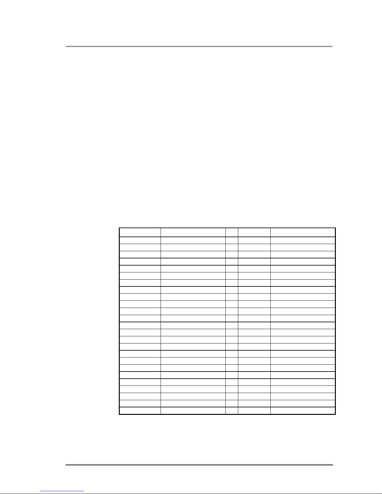
MX32x32DVI-HDCP-Pro and HDMI-Pro
User’s Manual v1.0
Page 91/ 109
7.2. About Advanced EDID Management
The EDID router contains a 164-block non-volatile memory bank. EDID List is
structured as follows:
1..50 Factory Preset EDID list
51..100 User programmable memories
101..132 (OUT_1...32) Last attached monitor’s EDID list
133..164 (IN_1...32) Emulated EDID at input connectors
All EDID (including factory preset; user programmable memories; EDID at other
inputs; and EDID at outputs) can be switched and emulated at any of the inputs
Info: The first 50 EDID (1…50 inclusive) are factory preprogrammed and cannot be
modified. These are the most commonly used resolutions.
Info: Lightware matrices can handle both 128 Byte EDID and 256 Byte extended EDID
structures.
Info: The attached monitor’s EDID is stored automatically, until a new monitor is
attached to that particular output. In case of powering off the unit, the last attached
monitor’s EDID remains in the non-volatile memory.
Info: All factory EDID contains CEA extension which states that the device is HDMI
compliant and supports deep color modes. This allows the sources to send HDMI
signal if they are capable of it. The matrix is able to convert HDMI signals back to
DVI on the output ports if you have DVI capable display devices.
MEMORY Resolution MEMORY Resolution
01 640x480@60 Hz 26 1600x1200@50 Hz
02 640x480@75 Hz 27 1600x1200@60 Hz
03 848x480@60 Hz 28 1920x1200@60 Hz
04 800x600@50 Hz 29 1920x1200@50 Hz
05 800x600@60 Hz 30 480i@60 Hz
07 1024x768@50 Hz 32 720x480p@60 Hz
08 1024x768@60 Hz 33 576i@50 Hz
09 1024x768@75 Hz 34 720x576p@50 Hz
10 1152x864@75 Hz 35 1280x720p@50 Hz
11 1280x768@50 Hz 36 1280x720p@60 Hz
12 1280x768@60 Hz 37 1920x1080i1@50 Hz
13 1280x768@75 Hz 38 1920x1080i2@50 Hz
14 1360x768@60 Hz 39 1920x1080i@60 Hz
15 1364x768@50 Hz 40 1920x1080p@24 Hz
16 1364x768@60 Hz 41 1920x1080p@25 Hz
17 1364x768@75 Hz 42 1920x1080p@30 Hz
18 1280x1024@50 Hz 43 1920x1080p1@50 Hz
19 1280x1024@60 Hz 44 1920x1080p2@50 Hz
20 1280x1024@75 Hz 45 1920x1080p@60 Hz
21 1366x1024@60 Hz 46 2048x1080p1@50 Hz
22 1400x1050@50 Hz 47 2048x1080p2@50 Hz
23 1400x1050@60 Hz 48 2048x1080p@60 Hz
24 1400x1050@75 Hz 49 Universal EDID
25 1680x1050@60 Hz 50 2560x1600p@60 Hz
Page 92
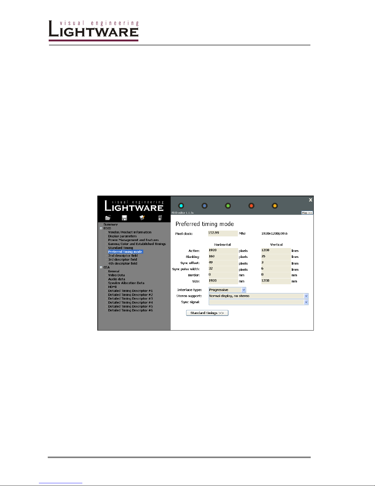
Page 92 / 109
The factory EDID 49 has an exceptional role: the so-called Universal EDID stores
as many resolutions and capabilities as possible. If you want to get the best
available quality (i.e. highest supported resolution and audio) then it is a good shot
to emulate Universal EDID to the inputs. The matrix emulates also this EDID as
factory default.
Please note that in order to get the highest available quality, all factory EDID states
compatibility with all audio formats. If your display or A/V receiver is not capable of
accepting some compressed audio formats that your source supports, then a
factory EDID will result in no audible sound.
7.3. About the Advanced EDID Manager
The Lightware Control Software has a built-in EDID editor component, which is
accessible from both the input and output settings window. This program allows
you to create, modify and save unique EDID with any content you want. The
modified data can be uploaded to the router memory or saved to file.
EDID is a complex standard so numerous settings can be done here.
DVI sources usually select their resolution based on the preferred timing mode.
HDMI devices use short video descriptors if they are available. Short video
descriptors can be edited by clicking Video Data in the left menu. Available audio
formats can be set on the audio data page.
Note: Most set-top-boxes and blu-ray players have audio settings menu that can override
the EDID information. Please refer to the manual of your device for further details.
Page 93
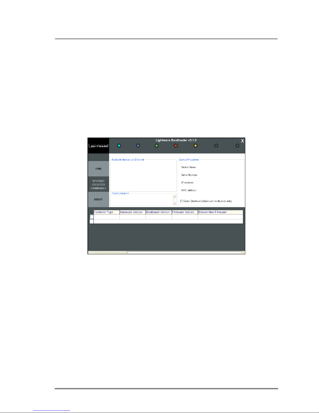
MX32x32DVI-HDCP-Pro and HDMI-Pro
User’s Manual v1.0
Page 93/ 109
8. FIRMWARE UPGRADE
Using Lightware bootloader application to upgrade router’s firmware
The matrix router can only be updated via LAN, so connect the matrix router to the
local subnet. The router is DHCP enabled so it will get an IP address automatically,
or if you do not have DHCP server, it will get an AUTO IP address from the AUTO
IP domain.
Run “Installer_LW_bootloader.exe”
Run the application from
Start Menu->Programs->Lightware- >LW_bootloader->LW_bootloader
Click “FIND” Button. If the bootloader finds one or more routers their IP addresses
will be listed in the tree view window. In the tree view, device type and serial
number are shown after the IP address. Double click on the IP address, then click
“YES” to establish connection with the matrix router. It will take 10-15 seconds to
get all information from the router.
Info: Note, that you must wait until all the devices on the network start up completely,
before pressing FIND button.
The bootloader application will reset the router during the firmware upgrade.
Page 94
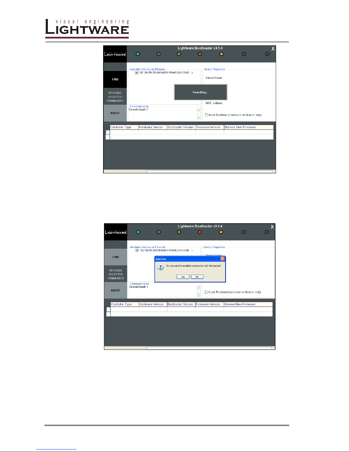
Page 94 / 109
Select the controller(s) that need(s) new firmware by clicking the checkbox next to
it. An open file dialog will pop up if you click on the last cell of the appropriate row.
Now you can browse for the new firmware file to upload. After opening the new file,
the new firmware field will contain the name of the firmware file.
Page 95
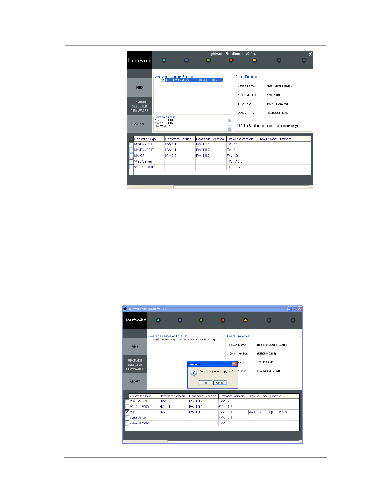
MX32x32DVI-HDCP-Pro and HDMI-Pro
User’s Manual v1.0
Page 95/ 109
Click “UPGRADE SELECTED FIRMWARES” button. The router is being
reprogrammed with the selected firmware after clicking on ”YES” button. If you
select a file that does not fit for the selected controller, you will get an information
message about which file is wrong. If you selected a controller to upgrade, but you
had not selected a file for it, then you will also get an information message about
which file is missing.
Quick Bootload mode can be switched on or off any time. It makes the bootloader
software faster by only checking the checksum of the controller. No data
verification is done after writing if the checksum was correct.
Info: The reprogramming time will vary between 3-8 mins per controller.
Page 96
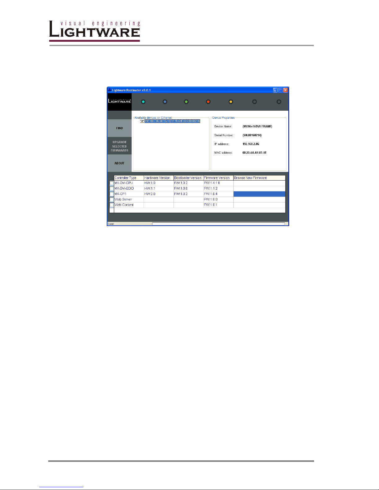
Page 96 / 109
When the firmware upgrade is done, you will get the following window:
When all upgrades are done, you can close the connection with the last device, by
closing the application, or you can select another matrix router to upgrade. After
closing the bootloader application, switch the upgraded devices off and then on.
Now the router is ready to be used with the new firmware.
Info: After closing the bootloader application the router will reset!
Page 97

MX32x32DVI-HDCP-Pro and HDMI-Pro
User’s Manual v1.0
Page 97/ 109
9. Troubleshooting
9.1. Serial connection problems
Check the cable and software settings
Check whether your null-modem cable is properly connected. In most cases there
are more COM ports present in the operating system. Please verify the connection
settings of your software. The router communicates with 9600 Baud, 8 data bit, No
parity, 1 stop bit.
Check the protocol
Check whether the proper protocol is selected (see Page 38). Select Protocol #1 in
order to use the matrix with the controller software.
Check the router
Check whether the router is properly powered and whether CPU LIVE LED is
blinking. Try performing a reset and verify that the default screen is on the LCD
(see Page 34). Check the router health status from the front panel.
9.2. TCP/IP connection problems
Check the IP settings and the cable
Check the IP address on the front panel of the matrix. If IP collision happens, a
notification message will appear. Try setting up the IP address and the subnet
mask manually if it is necessary. Check whether your computer’s firewall blocks the
selected port. Check the cable: if you connect it directly into your computer, it has
to be a cross-link cable.
Check alive connections
Only one connection is allowed simultaneously. Check whether there is another
open collection (e.g. opened router web, running control software over ethernet).
Try restarting the router if you have no other option.
9.3. There is no picture
Check the cables
Due to the high data rates, the cables must fit very well. DVI connectors have to be
locked with screws, no tensions or breaches are allowed. If your source or display
has more connectors then make sure that the proper interface is selected.
Check the crosspoint matrix
Check the connection between the input and output port either on the front panel or
from web or the control software. Check whether the output is muted or not.
Page 98

Page 98 / 109
Check the incoming signal
Run the control software or the web and select the HDMI input settings. Check
whether video signal is present on the input or not. If there is no video signal, then
please continue at chapter 9.4.
Check the outgoing signal
Select the HDMI output settings in the control software or the web page. Check
whether the video signal is present at the output or not. Try reloading factory
default settings to the output. If the HotPlug or the display data is not present,
make sure that your display device is configured properly.
Check EDID related problems
Maybe your display device is not capable of receiving the sent video format. Try
emulating your display device’s EDID to the source. You will find help to this
process on Page 36, Page 72 or Page 85. If you get a picture now, you have an
EDID related issue, please read the Advanced EDID Management chapter on page
90 for more details.
Check router health
Check the router health status and verify that DC voltages are present and fans are
working. (see Page 35, Page 74 or Page 86).
9.4. There is no input signal
Check the source
Check whether your source is powered on and configured properly. The HDMI
output can be turned off on most DVD players. If the source is a computer, then
verify that the DVI output is selected and active. Try restarting your computer; if
you get a picture during the booting process, you have to review the driver settings.
Check the cable equalization
Start the controller software or the webpage and verify at the input settings that the
cable equalization is set properly. The automatic cable equalization is the best
option in most cases, but you have to set it manually if you are working with very
long cables.
Check the EDID
Maybe the data rate is too high for that type of cable. Try switching another EDID
to the inputs with lower resolution. If the source is a computer and you are an
expert user, you can try modifying the refresh rate in the preferred timing descriptor
by lowering the clock frequency, so you would be able to get it to work at higher
resolutions over a noisy connection.
If your source is an HDMI device, it is a good idea to disable the deep color support
in the EDID. This way the data rate can be reduced by 30% at the expense of very
small quality loss.
Page 99

MX32x32DVI-HDCP-Pro and HDMI-Pro
User’s Manual v1.0
Page 99/ 109
9.5. There is no sound
Note: High-Bit-Rate audio formats such as Dolby True-HD or DTS-HD Master Audio
cannot be sent over the S/PDIF cable.
Check incoming audio
Start the controller software or the webpage and verify the incoming audio at the
input settings. If there is no audio on the input, you should try changing the
emulated EDID or review the settings of your source.
Check the outgoing format
Start the controller software or the webpage and verify the mode at the output
settings. If the port operates in DVI mode, you can try forcing HDMI operation.
Note: The S/PDIF outputs work both in HDMI and in DVI modes.
Check the EDID
It is possible that your device doesn’t support the sent audio format. Try emulating
your display device’s EDID to the source. You will find help to this process on Page
36, Page 72 or Page 85. If you get a picture now, you have an EDID related issue,
please read the Advanced EDID Management chapter on Page 90.
Page 100
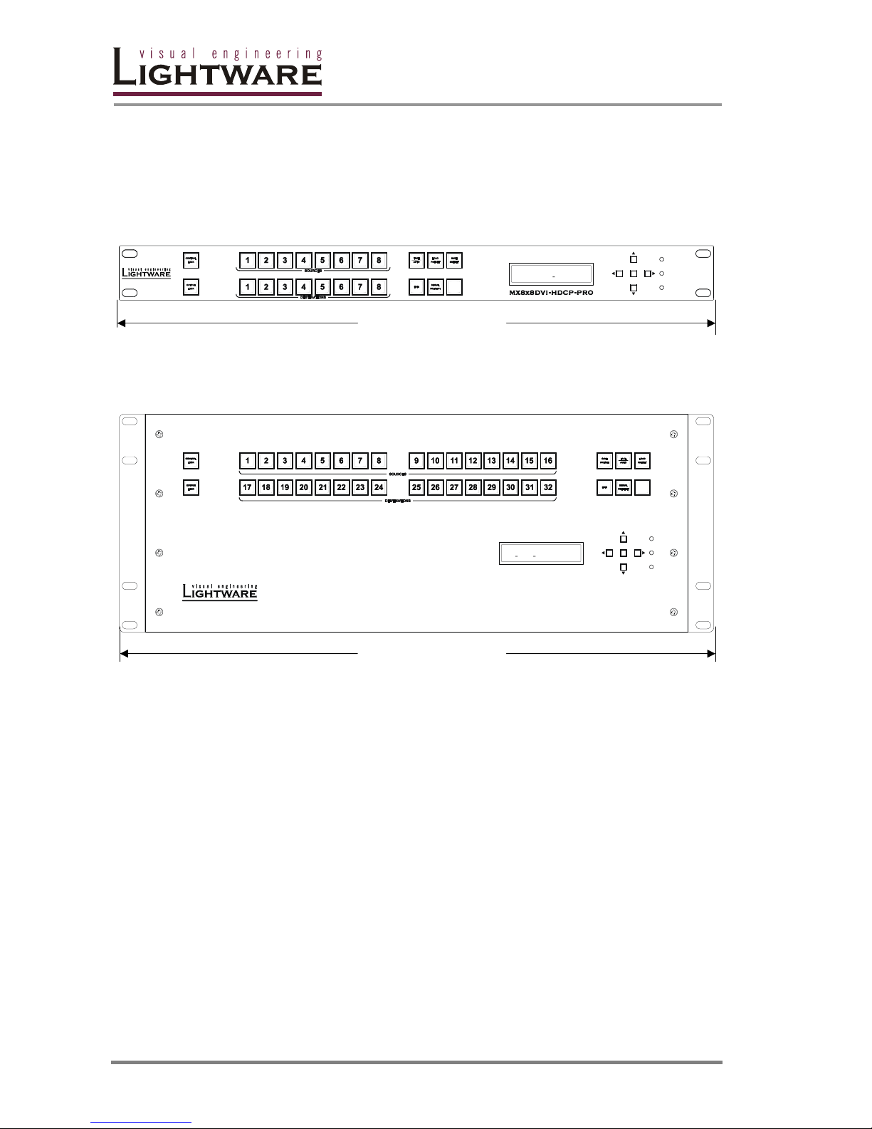
Page 100 / 109
10. Mechanical Drawings
10.1. Front view
ENTER
CPU LIVE
POWER
RESET
ENTER
CPU LIVE
POWER
RESET
LIGHTWRAE
MX8x8HDCPProDVI
482 mm
MX8X8 series
16 16 DIGITAL MATRIX ROUTERx
ENTER
CPU LIVE
POWER
RESET
MX-DVI-FR16
M
LIGHTWRAE
XDVIFR1
6
482 mm
MX-DVI-FR16
 Loading...