

Lightware MX2-8x8-DH-4DPi-A, MX2-8x8-DH-8DPi-A, MX2-8x8-DH-4DPio-A, MX2-8x8-DH-8DPio-A, MX2-16x16-DH-8DPi-A-R User guide
...Page 1
Quick Start Guide
5
3
7
6
Menu navigation
& change parameter
Menu selection
MX2-8x8-DH-4DPi-A; MX2-8x8-DH-8DPi-A;
MX2-8x8-DH-4DPio-A; MX2-8x8-DH-8DPio-A;
MX2-16x16-DH-8DPi-A-R; MX2-16x16-DH-16DPi-R;
MX2-24x24-DH-12DPi-R, -A-R; MX2-24x24-DH-24DPio-A-R;
MX2-32x32-DH-16DPi-A-R; MX2-48x48-DH-48DPi-A-R;
MX2-48x48-DH-24DPio-A-R; MX2-48x48-DH-48DPio-A-R
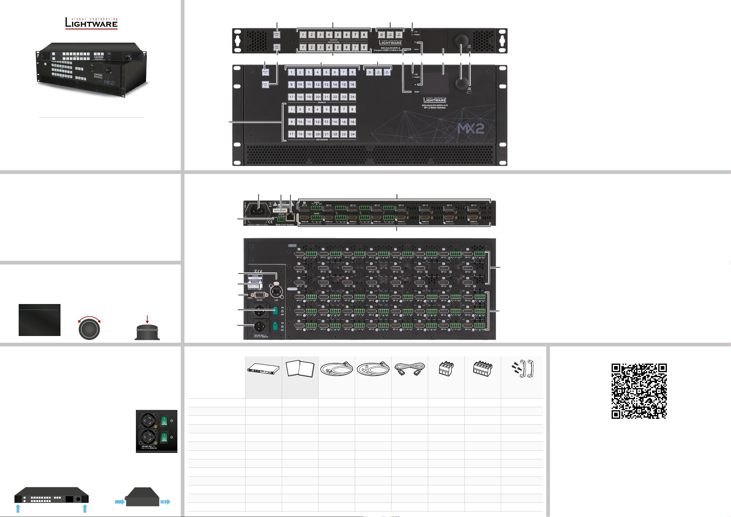
Front View of MX2-8x8-DH-8DPi-A and MX2-24x24-DH-24DPio-A-R
3
3 4
DESTINATIONS
2
2
1
5
5
8
6
6
q97w
Output Lock Locks one or more outputs.
1
Control Lock Disables or enables front panel operations. Red light means
2
Sources Buttons to select an input, to select a preset number or to
3
Destinations Buttons to select an output or to see the state of an output.
4
Function Buttons Function buttons switch between working modes (Take /
5
Status LEDs Blinking LIVE LED indicates normal operation; POWER
6
IR detector LED Reserved for future developments.
7
Reset Button Reboots the matrix (the same as disconnecting from the
8
Color Display LCD screen shows the most important settings and
9
Jog Dial Control
q
Knob
USB Control USB connector for local control functions (e.g. Lightware
w
the switching and function buttons are disabled.
view the state of the selected input port.
Autotake) and perform Preset operations.
LED is dark in the case of an internal voltage problem.
power source and reconnecting again).
parameters in the front panel menu.
Easy setting and menu navigation by the jog dial control.
Device Controller (LDC) software).
Important Safety Instructions
Please read the supplied safety instruction document before using the product and keep it
available for future reference.
Introduction
The Lightware MX2 standalone matrix switcher series is equipped with mixed DisplayPort
and HDMI ports, and supports uncompromised 4K UHD resolution at 60Hz with RGB 4:4:4
colorspace and with down-conversion capabilities to 4:2:2. The DisplayPort inputs on the MX2
DPi series routers allow connecting DisplayPort 1.2 video sources directly, without the need for
adapters or dongles. Additional analog audio input and output connectors allow embedding a
different audio signal in the video stream or break out the audio signal from the HDMI stream
on the output.
Front Panel Operations - LCD Menu and Navigation
The front panel has a color LCD showing the most important settings and parameters (E.g.
network settings, video settings, port status, crosspoint state). The jog dial control knob can be
used to navigate between the menu items or change the value of a parameter. The knob can
be pressed to enter a menu or edit/set a parameter.
MAIN MENU
System Settings
Input Ports
Output Ports
EDID
Health
Presets
Turn
& set parameter
Press
Powering On
Connect the power cords to the AC input of the Power Supply Units (PSU). The 1RU- high
models are immediately powered on. After the self-test (about 20 seconds), the router reloads
its last conguration and it is ready to use.
After switching ON, the router reloads the latest settings that were used before it was
switched off. The router has an internal emergency memory that stores all current settings
and the conguration.
Redundant Power Supplies
The -R sufx in the model name shows that the model has redundant
PSUs, which can be switched on and off without interrupting the
video transmission. Using one or both of the PSUs at the same
time is also possible.
The double PSU allows to connect them to two different AC power
lines to ensure the continuous power for the matrix.
Ventilation
To ensure the correct ventilation and avoid overheating, leave enough free space
around the appliance. Do not cover the appliance, leave the ventilation holes free.
The following pictures show the direction of the airow:
Rear View of MX2-8x8-DH-8DPi-A and MX2-24x24-DH-24DPio-A-R
1 45
4
3
2
1
Box Contents
Safety and
Warranty
Info
Matrix switcher
MX2-8x8-DH-4DPi-A
ON
OFF
ON
OFF
MX2-8x8-DH-8DPi-A
MX2-8x8-DH-4DPio-A
MX2-8x8-DH-8DPio-A
MX2-16x16-DH-8DPi-A-R
MX2-16x16-DH-16DPi-R
MX2-24x24-DH-12DPi-R
MX2-24x24-DH-12DPi-A-R
MX2-24x24-DH-24DPio-A-R
MX2-32x32-DH-16DPi-A-R
MX2-48x48-DH-24DPio-A-R
MX2-48x48-DH-48DPi-A-R
MX2-48x48-DH-48DPio-A-R
Safety and
warranty info, QSG
Start
Guide
Quick
IEC power cable
-
-
-
-
-
-
-
-
-
Neutrik powerCON
power cable
- -
- -
- -
- -
(2x)
(2x)
(2x)
(2x)
(2x)
(2x)
(2x)
(2x)
(2x)
6
7
Serial data cable
(male-female)
Phoenix® combicon
3-pole connector
(2x)
(8x)
(16x)
(16x)
-
- - -
- - -
-
-
-
-
-
-
Phoenix® combicon
5-pole connector
(16x)
(20x)
(20x)
(28x)
(32x)
(32x)
(32x)
Handle pair with 4 pcs
M5 at head screws
-
-
-
-
-
-
-
AC Connector -R sufxed models: Neutrik powerCON connector accepting
1
Power Switch The matrix can be switched on/off by the power switch.
2
Service Button Hidden button for special operations.
3
RS-232 Port -R sufxed models: 9-pole D-SUB connector.
4
LAN -R sufxed models: Neutrik etherCON connector for
5
Input Ports HDMI input ports are able to receive HDMI 2.0 video signal.
6
Output Ports DP or HDMI output ports for connecting sink devices.
7
The User’s Manual is also available via the QR code below:
100-240 V, 50 or 60 Hz
In the other models: Standard IEC connector accepting
100-240 V, 50 or 60 Hz.
Other models: 3-pole Phoenix connector.
Ethernet/LAN connection.
Other models: RJ45 connector to control the matrix via
LAN/Ethernet.
DP input ports for DP 1.2 video signal.
Audio input ports (5-pole Phoenix) for balanced analog
audio input signal (in -A sufxed models).
Audio output ports (5-pole Phoenix) for balanced analog
audio output signal. The signal is de-embedded from the given
video port (in -A sufxed models).
Lightware Visual Engineering PLC.
Budapest, Hungary
[email protected] +36 1 255 3800
[email protected] +36 1 255 3810
©2023 Lightware Visual Engineering. All rights reserved. All trademarks mentioned are the
property of their respective owners. Specications are subject to change without notice.
Further information on the device is available at www.lightware.com.
Doc. ver.: 1.7
19210080
Page 2
Front Panel Operations
DP
DP
AUDIO Output
AUDIO Input
TX RX
5: Ground
TX RX
5: Ground
4K PC
MacBook
DP monitor
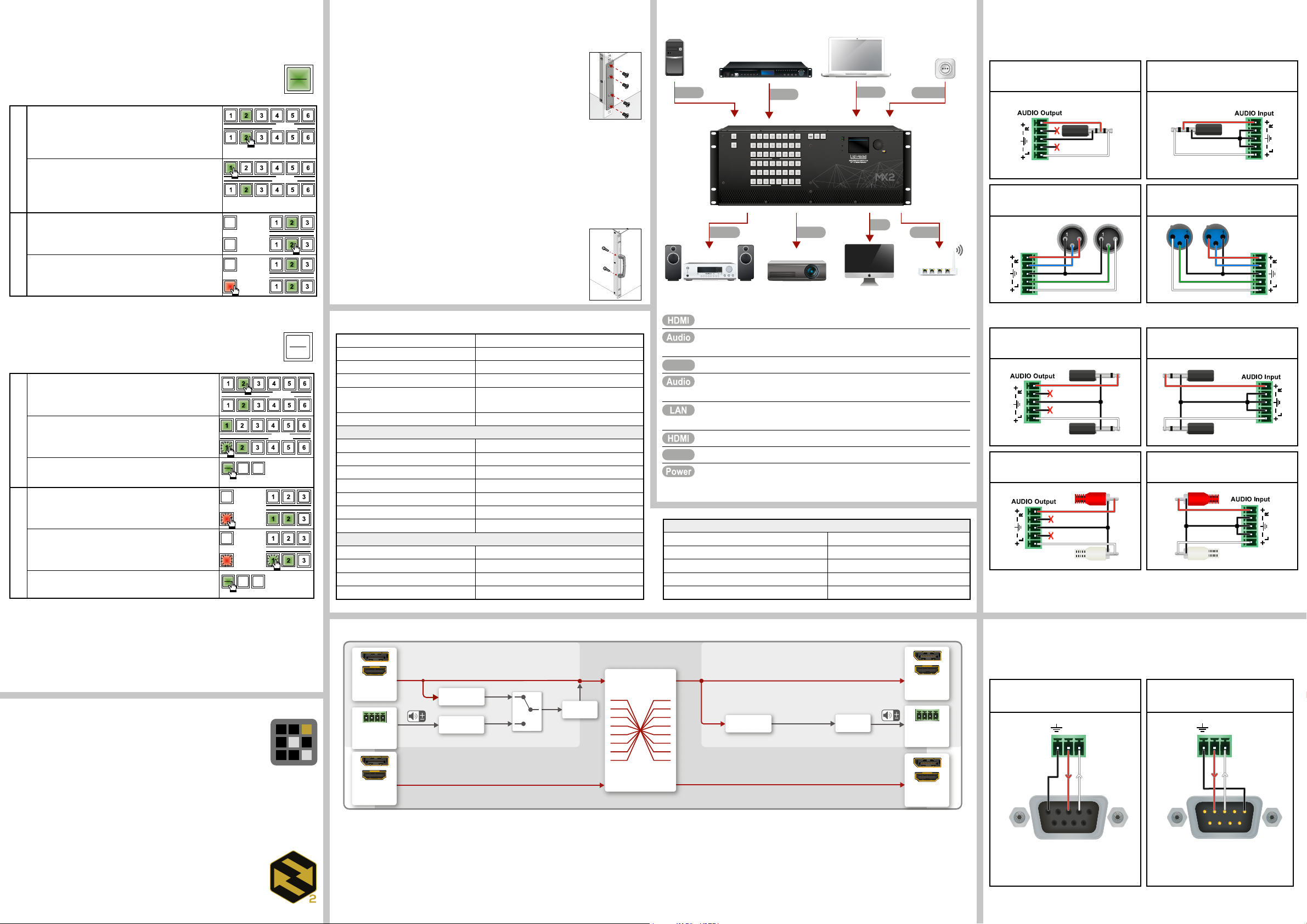
Press and hold the Take button for two seconds to change between Take and Autotake modes.
When the Take button continuously shines green, Autotake mode is selected.
Switching and Locking Operations in AUTOTAKE Mode
Autotake mode is useful when immediate actions must be taken, or fast switching
is needed between sources on a particular destination. In this mode switching
occurs immediately upon pressing one of the input selector buttons.
1. Press and release the desired destination button. The
pressed destination button and the currently connected
source button light up green. If no source is connected (the
output is muted), no source button will light up.
2. Press and release the desired source button. The
switch action will be executed immediately. Switching
between sources to the selected destination can be done
Switching Operations
directly.
1. Press and release the required destination button.
Now the selected destination button and the currently
congured source button light up (view mode).
2. Press and release the Output Lock button; it lights up
in red, and lock function is activated at once. No source
Locking an Output
can be changed at the locked destination.
CONTROL
OUTPUT
CONTROL
OUTPUT
LOCK
LOCK
LOCK
LOCK
SOURCES
DESTINATIONS
SOURCES
DESTINATIONS
TAKE
AUTO
Mounting Options
M4x8 size is the longest allowed screw for xing the ears to the housing. Longer
screws may touch internal parts.
Mounting as a Standard Rack Installation - with front rack ears
All models can be mounted into the rack cabinet.
Two rack ears are supplied with the product, which are xed on the left and
the right side. The default position allows mounting the device as a standard
rack unit installation.
Under-desk Mounting - with front and rear rack ears
Under-desk mounting is available for the 1U-high models.
1. Release and remove the xing screws of both rack ears from the matrix.
2. Rotate the rack ears by 90° to the desired direction.
3. Insert the screws into the holes and x the front ears to the matrix.
4. Fix the two other rear ears (not supplied with the product) by the screws on both sides.
5. Fix the matrix by the rack ears to the desired surface (screws not supplied).
Two rack ears are supplied with the product; further rack ears can be purchased separately.
Fixing the Handles
Two handles can be mounted on the rack ears of the 8 RU-sized matrix
switchers. Fasten the 2 x 2 pcs xing screws to x the handles to the rack
ears.
Connecting Steps - MX2-24x24-DH-12DPi-A-R
Media Player
Audio
Audio amplifier
CCOONNTTRROOLL
LLOOCCKK
OOUUTTPPUUTT
LLOOCCKK
1 2 3 4 5 6 7 8
9 10 11 12 13 14 15 16
17 18 19 20 21 22 23 24
SOURCES
1 2 3 4 5 6 7 8
9 10 11 12 13 14 15 16
17 18 19 20 21 22 23 24
DESTINATIONS
4K projector
LLOOAADD
LLOOAADD
SSAAVVEE
SSAAVVEE
TTAAKKEE
TTAAKKEE
PPRREESSEETT
PPRREESSEETT
PPRREESSEETT
PPRREESSEETT
AAUUTTOO
AAUUTTOO
HDMI LANAudio
Audio Cable Wiring Guide
The -A sufxed models ha analog audio input and output ports, which are built with 5-pole
Power outlet
DP
LIVE
MAIN MENU
POWER
System Settings
Input Ports
Output Ports
IR
EDID
Health
USB
CTRL
Presets
RESET
PowerHDMI
DP
Ethernet
Phoenix input and output connectors. See below a few examples of the most common
assembling cases.
Balanced output to unbalanced input
Phoenix - 3.5 (1/8”) TRS
Balanced output to balanced input
Phoenix - 2 x XLR
2
3
2
3
Unbalanced output to balanced input
3.5 (1/8”) TRS - Phoenix
Balanced output to balanced input
2 x XLR - Phoenix
2
2
3
3
Switching and Locking Operations in TAKE Mode
Take mode allows the user to connect or disconnect multiple outputs to an input
at once. This mode is useful when time delay is not allowed between multiple
TAKE
AUTO
switching. The commands are only realized when the Take button is pressed.
1. First press and release the desired source button.
The pressed source button and all destination buttons
SOURCES
DESTINATIONS
that are currently connected to the source light up.
2. Press and release the desired destination buttons
that have to be (dis)connected from/to the selected
SOURCES
DESTINATIONS
source. The preselected destination buttons will blink.
TAKE
SAVE
Switching Operations
3. Press and release the Take button. The selected
LOAD
PRESET
PRESET
AUTO
input is switched to the selected output(s).
1. Press and release the Output Lock button. It starts
to blink and all the buttons of any locked destinations
light up (view state).
2. Press and release a destination button. It starts to
blink (more destinations can be selected sequentially).
Locking an Output
3. Press and release the Take button. The selected
CONTROL
OUTPUT
CONTROL
OUTPUT
LOCK
LOCK
LOCK
LOCK
TAKE
SAVE
LOAD
PRESET
PRESET
AUTO
destinations are now locked.
Control Lock
If the button shines in red, the switching and function buttons, and the jog dial control knob
are disabled. Press and hold the Control lock button for three seconds to toggle the state.
When the front panel buttons are locked, remote control (RS-232, USB, Ethernet) is still
available.
Software Control – Using Lightware Device Controller (LDC)
The device can be controlled from a computer using the Lightware Device
Controller software. The application is available at www.lightware.com
(Support / Downloads section), install it on a Windows PC or a macOS and
connect to the device via LAN, USB, or RS-232.
Software Control – Built-in Web
The built-in website of the matrix allows to connect and control the matrix via a web browser.
Open a web browser (Mozilla Firefox or Google Chrome is recommended) and connect the
device by writing the IP address of the matrix into the address bar.
The built-in web and Lightware Device Controller Software have the same look and
functionality.
Firmware Upgrade
Lightware Device Updater2 (LDU2) is an easy and comfortable way to
keep your device up-to-date. Establish the connection to the device via
Ethernet. Download and install LDU2 software from the company’s website
www.lightware.com, where you can nd the latest rmware package as well.
Factory Default Settings
IP address Dynamic (DHCP is enabled)
RS-232 port setting 57600 BAUD
RS-232 port control protocol LW3 protocol
Crosspoint setting I1 to all
Emulated EDID F49 - (Universal HDMI, all audio, deep color
support)
EDID memory storage 144 factory / 100 User memory slots
HDMI ports
HDCP enable (in) Allow HDCP 2.2 and HDCP 1.4
Audio source (in) HDMI
HDCP (out) Depends on input
Signal type (out) Auto
Conversion mode (out) Passthrough
Audio mode: HDMI port (out) HDMI
Audio mode: HDMI with a. audio (out) HDMI+ANALOG
DP ports
HDCP enable (in) Allow HDCP 2.2 and HDCP 1.4
Link data rate (in) Max. HBR2 (5.4 Gbps)
Link lane count (in) Max. 4 lane
Audio source (in) DisplayPort
Port Diagram
Audio options in -A suffixed models
DP/ HDMI
in
Analog
De-embedder
converter
A/D
Digital
audio
Digital
audio
Embedder
audio in
DP/ HDMI
in
Video Options
DisplayPort signals over 18Gbps will be converted down by either truncating bit depth or by
converting RGB signal to YCbCr 4:2:2 12-bit signal based on user selection. The second
option will not reduce the color depth, instead it results in loss of chroma information.
The test pattern generator feature makes it possible to transmit the analog audio without any video
signal.
Connect the desired source to an HDMI input port.
Optionally connect an audio source to the Audio input port, which is located
next to the connected HDMI input port.*
Connect the desired source to a DP input port.
Optionally connect an audio device (e.g. amplier) to the Phoenix Audio
output port, which is located next to the connected HDMI output port.*
In order to control the matrix via Ethernet, connect the device to a LAN switch/
router, and connect a controller (e.g. Touch panel).
Connect a sink device to an HDMI output port.
Connect a sink device to an DP output port.
Connect the power cord to the AC power socket and to the matrix.
* MX2-24x24-DH-12DPi-R has no analog audio port.
DP ports
Power (in, out) Enabled
HDCP (out) Depends on input
Link training mode (out) Auto
Audio mode: DP port (out) DP
Audio mode: DP with analog audio (out) DP+Analog
Audio options in -A suffixed models
DP/ HDMI
out
De-embedder
Digital
audio
D/A
converter
Analog
audio out
DP/ HDMI
out
Analog Audio Options
The -A sufx in the model name refers to the analog audio option. An external audio signal
can be embedded in the HDMI stream by the Analog Audio input port. In this case the audio
from the analog input port is converted and embedded into the HDMI stream. Furthermore, the
Analog audio output ports allow to de-embed the audio of the HDMI output stream.
Please note that only stereo LPCM can be de-embedded from the HDMI signal.
Balanced output to unbalanced input
Phoenix - 2 x 6.3 (1/4”) TS
Balanced output to unbalanced input
Phoenix - 2 x RCA
Unbalanced output to balanced input
2 x 6.3 (1/4”) TS - Phoenix
Unbalanced output to balanced input
2 x RCA - Phoenix
Wiring Guide for RS-232 Data Transmission
Certain models are built with a 3-pole Phoenix connector. See the examples below of
connecting to a DCE (Data Circuit-terminating Equipment) or a DTE (Data Terminal
Equipment) type device:
Lightware device and a DCE
D-SUB 9 - Phoenix
5
9
1
6
2: TX data
3: RX data
For more information about the cable wiring, see the user’s manual of the device or the
Cable Wiring Guide on our website www.lightware.com.
Lightware device and a DTE
D-SUB 9 - Phoenix
1
6
5
9
2: TX data
3: RX data
 Loading...