

Page 1
Quick Start Guide
765
8
9qwert
3
4
2 1
4
RS232
2 1
3
6
5
II
RR
OO
UU
TT
Reset
3
4
RX TX RX TX
2 1
TX TX
4
RS232
2 1
3
MIC IN
AUDIO OUT
AUDIO IN
L R
6
5
II
RR
OO
UU
TT
MMX8x8-HT080
Front view
54
3
2
1
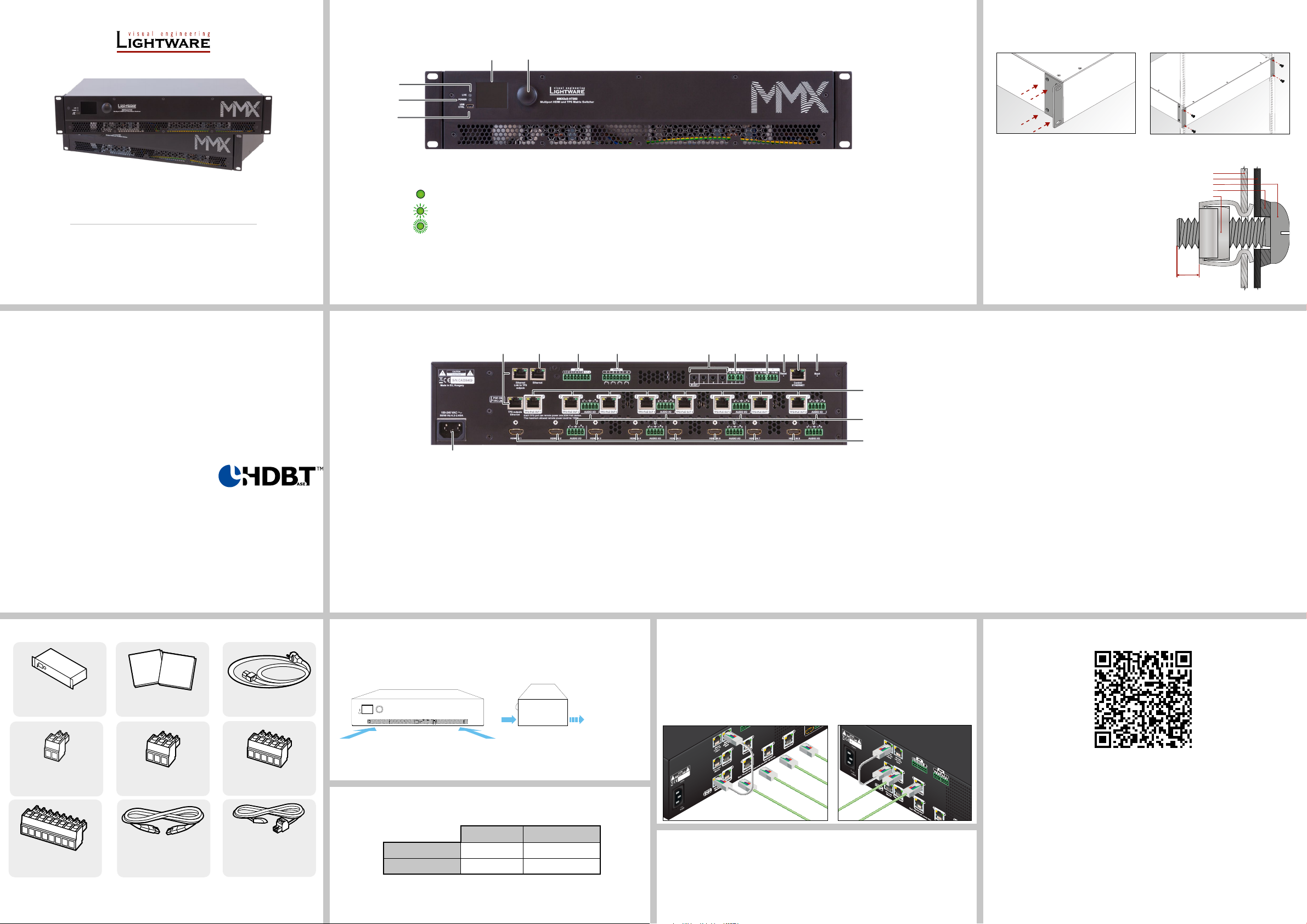
USB port USB mini-B port for controlling the unit locally by the Lightware Device Controller software.
1
POWER LED on Power LED indicates that the unit is powered on.
2
LIVE LED blinking slow The unit is on and operates properly.
3
blinking fast The unit is in bootload mode.
LCD screen Displays the front panel menu. Basic settings are available.
4
5
Jog dial
knob
Browse the menu by turning the knob, click on the desired item to check or change it.
Mounting Options - Standard Rack Installation
Two rack ears are supplied with the product, which are xed on left and right side as shown in
the picture. The default position allows mounting the device as a standard rack unit installation.
The matrix switcher is 2U-high and one-rack wide.
¢
Always use all four screws for xing
the device ears to the rack rail. Choose
properly sized screws for mounting. Keep
a minimum of two threads left after the nut
screw.
Ventilation
To ensure the correct ventilation and
¢
avoid overheating, leave enough free
space around the appliance. Do not cover
the appliance, leave the ventilation holes
free on both sides.
rack shelf mounting ear
rack rail
rack screw
flat washer
cage nut
min. 2
threads left
Important Safety Instructions
Please read the supplied safety instruction document before using the product and keep it
available for future reference.
Introduction
The MMX8x8-HT080 is a standalone matrix switcher offering eight HDMI video inputs and
eight TPS video outputs. Additional analog audio input and output connectors allow to embed
a different audio signal in the HDMI stream or break out the audio signal from the HDMI stream
on the output. 4K / UHD (30Hz RGB 4:4:4, 60Hz YCbCr 4:2:0), 3D capabilities and HDCP are
fully supported. The matrix is compatible with the HDMI 1.4 standard. The feature allows to
switch video signals up to 4K@30Hz 4:4:4 color space from any input to any output.
Compatible Devices
The MMX8x4-HT420M matrix is compatible with other
Lightware TPS devices, matrix TPS and TPS2 boards, 25G
boards, as well as third-party HDBaseT-extenders, but not
compatible with the phased out TPS-90 extenders.
TM
HDBaseT
and the HDBaseT Alliance logo are trademarks of the HDBaseT Alliance.
Box Contents
Quick
Safety and
Start
Warranty
Guide
Info
Matrix unit IEC power connector
Safety and warranty info,
Quick Start Guide
Rear view
1
AC connector Standard IEC connector accepting 100-240 V, 50 or 60 Hz.
1
HDMI inputs HDMI input ports (4x) for sources.
2
Audio I/O
3
ports
TPS outputs RJ45 connectors (8x) for outgoing TPS signal; PoE-compliant.
4
Boot button Resetting or powering on the device while keeping the hidden
5
Ventilation
¢
To ensure the correct ventilation and avoid overheating, leave enough free space
around the appliance. Do not cover the appliance, leave the ventilation holes free on
both sides.
5-pole Phoenix connector for balanced analog audio; depending
on the configuration, it can be input or output. Output audio is the
de-embedded HDMI signal from the nearby HDMI port.
button pressed puts the matrix in bootload mode.
4
3
2
Control Ethernet port RJ45 connector to control the matrix via LAN.
6
Reset button Reboots the matrix; the same as switching it off and on
7
RS-232 ports 3-pole Phoenix connectors (2x) for bi-directional RS-232
8
Serial/Infra outputs 2-pole Phoenix connectors (2x) for IR output or TTL
9
Infra outputs 3.5 mm TRS (Jack) plugs for infra signal transmission.
q
Ethernet Link to TPS inputs and TPS outputs
TPS lines do not transmit Ethernet signal, but they can be transmitted on the TPS input and
output ports, if there is a physical link between the motherboard and the input or the output
board. This makes it possible to control a third-party device or to supply Ethernet via TPS.
Connect a patch cable between
Ethernet Link to TPS inputs and TPS inputs Ethernet labeled RJ45 connectors or
Ethernet Link to TPS outputs and TPS outputs Ethernet labeled RJ45 connectors to
create a link.
again.
communication.
output serial signal.
Relay 8-pole Phoenix connectors for relay ports.
w
GPIO 8-pole Phoenix connector for configurable general purpose input/
e
Ethernet port Locking RJ45 connector for Ethernet connection to the matrix.
r
TPS Ethernet Locking RJ45 connectors to supply Ethernet communication for the
t
output ports.
TPS lines – they can be separated from the LAN communication
(controlling functions) of the matrix.
Not PoE-compliant.
The infrared emitter and detector units are optionally available accessories.
The User’s Manual is also available via the QR code below:
Phoenix Combicon 2-pole
Connector (4x)
Phoenix Combicon 8-pole
Connector (2x)
Phoenix Combicon 3-pole
connector (3x)
LAN straight-through
Cable, CAT5e type,
0.25m length (2x)
Phoenix Combicon 5-pole
connector (2x)
Infrared Emitter Unit
with Phoenix Combicon
2-pole Connector (2x)
Sn:
Made in EU, Hungary
100-240 VAC
50/60 Hz 1.4-0.85A
Sn:
Made in EU, Hungary
Serial Output Voltage Levels (TTL and RS-232)
TTL* RS-232
Logic low level 0 .. 0.25V 3 V .. 15 V
Logic high level 4.75 .. 5.0V -15 V .. -3 V
*Using a receiver with at least 1k impedance to any voltage between 0V and 5V to get the voltages,
but not compatible with the phased out TPS-90 extenders.
Remote Powering (PoE 48V)
The matrix is PoE-compatible (in accordance with IEEE 802.3af standard) and is able to send
remote power to connected TPS devices via the TPS connection (through the CATx cable).
No local power adaptor is required for the connected PoE-compatible TPS extender. The PoE
48V feature is enabled on TPS ports as factory default.
100-240 VAC
50/60 Hz 1.4-0.85A
MMX8x4-HT420M
Ethernet link to inputs
Ethernet link
to outputs
©2023 Lightware Visual Engineering. All rights reserved. All trademarks mentioned are the
property of their respective owners. Specications are subject to change without notice.
Lightware Visual Engineering PLC.
Budapest, Hungary
[email protected] +36 1 255 3800
[email protected] +36 1 255 3810
Further information on the device is available at www.lightware.com.
Doc. ver.: 1.2
19210075
Page 2
AUDIO Output
AUDIO Input
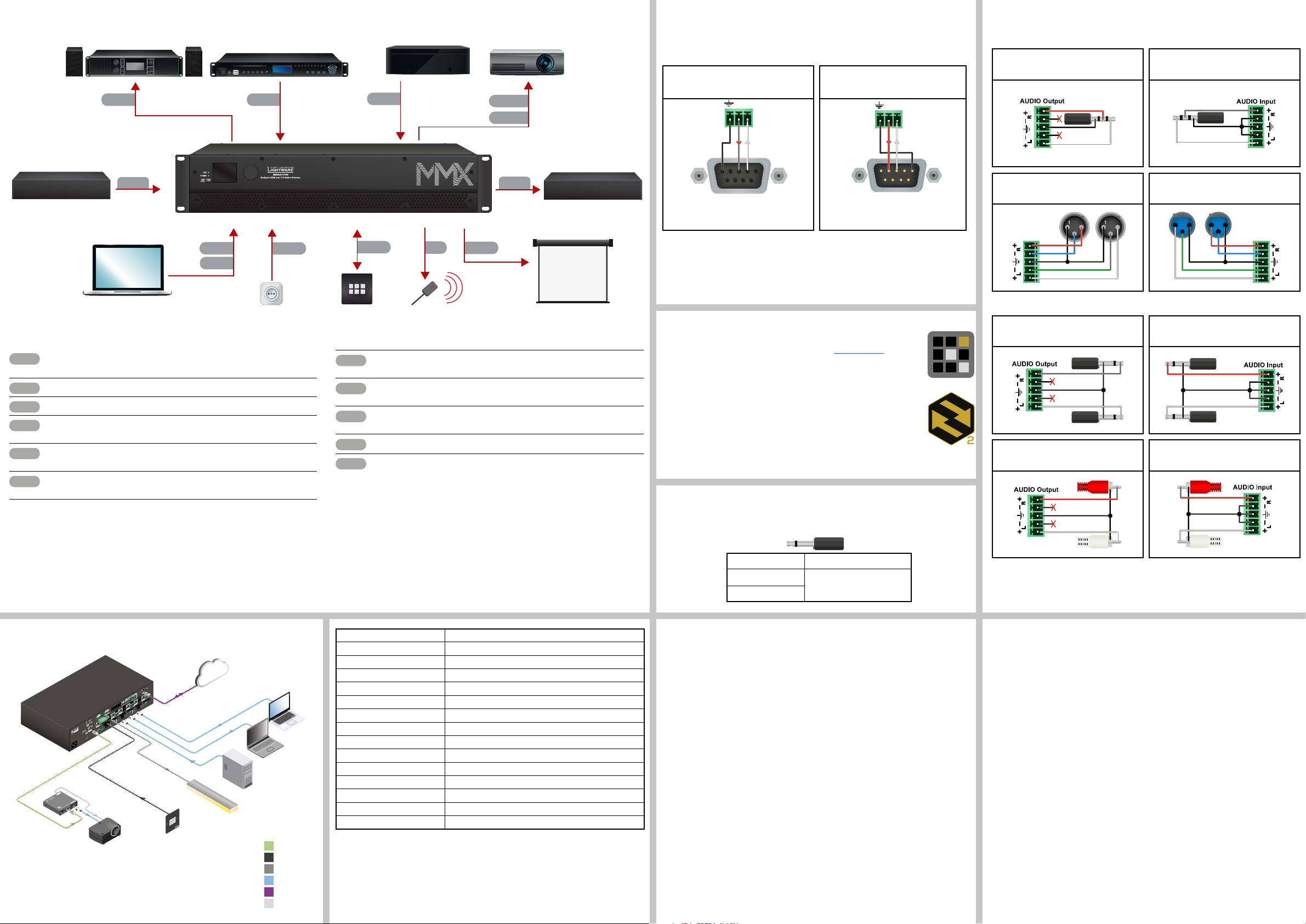
Connecting Steps
CATx
HDMI
HDMI
Audio
Audio
USB
LAN
Relay
IR
GPIO
Power
TX RX
5: Ground
TX RX
1 2
Laptop 1.
Audio Amplifier
+48
+36
+24
+15
+10
+6
+48
+36
+24
+15
+10
+6
Audio
Media Player
Audio
Wiring Guide for RS-232 Data Transmission
PC
HDMI
Projector
HDMI
MMX8x4 series matrix is built with a 3-pole Phoenix connector. See the examples below
of connecting to a DCE (Data Circuit-terminating Equipment) or a DTE (Data Terminal
Equipment) type device:
Lightware device and a DCE
D-SUB 9 - Phoenix
Lightware device and a DTE
D-SUB 9 - Phoenix
Audio Cable Wiring Guide
MMX8x4 series matrix is built with 5-pole Phoenix input and output connectors. See a few
examples below of the most common assembling cases.
From balanced output to unbalanced input
Phoenix - 3.5 (1/8”) TRS
From unbalanced output to balanced input
3.5 (1/8”) TRS - Phoenix
RS-232
CATx
TPS transmitter
device
Laptop
Connect a HDBase-TTM -compatible transmitter or matrix output board to TPS
input port. PoE-compliant.
Connect an HDMI source (e.g. PC) to the HDMI input port.
Connect an HDMI sink (e.g projector) to the HDMI output port.
Optionally for analog output port: connect an audio device (e.g. audio amplifier) to
the analog audio output port by an audio cable.
Optionally for audio input: connect the audio source (e.g. media player) to the
audio input port by an audio cable.
Optionally connect the USB cable in order to control the matrix switcher via the
Lightware Device Controller software.
MMX8x8-HT080
LAN
USB
Power outlet
Power
GPIO
Button panel
IR
Infra emitter
Relay
Optionally connect the UTP cable (straight or cross, both are supported) in order
to control the matrix switcher via the Lightware Device Controller software.
Optionally for relays: connect a controlled device(s) (e.g. a projection screen) to
the relay port.
Optionally connect the infra emitter to the infra output port (2-pole Phoenix or 1/8”
Stereo Jack connector) to transmit infra signal.
Optionally connect a controller/controlled device (e.g. button panel) to the GPIO port.
Connect the power cord to the AC power socket to the matrix unit.
Powering the device is recommended as the nal step.
CATx
Projection screen
TPS receiver
device
5
9
2: TX data
3: RX data
1
6
1
6
5
9
2: TX data
3: RX data
For more information about the cable wiring, see the user’s manual of the device or
Cable Wiring Guide on our website www.lightware.com/support/guides-and-white-papers.
Software Control – Using Lightware Device Controller (LDC)
The device can be controlled from a computer using the Lightware Device
Controller software. The application is available at www.lightware.com, install
it on a Windows PC or a macOS and connect to the device via LAN, USB,
or RS-232.
Firmware Update
Lightware Device Updater 2 (LDU2) is an easy and comfortable way to
keep your device up-to-date. Establish the connection to the device via
Ethernet. Download and install LDU2 software from the company’s website
www.lightware.com, where you can nd the latest rmware package as well.
From balanced output to balanced input
Phoenix - 2 x XLR
2
3
2
3
From balanced output to unbalanced input
Phoenix - 2 x 6.3 (1/4”) TS
From balanced output to unbalanced input
Phoenix - 2 x RCA
From balanced output to balanced input
2 x XLR - Phoenix
2
2
3
3
From unbalanced output to balanced input
2 x 6.3 (1/4”) TS - Phoenix
From unbalanced output to balanced input
2 x RCA - Phoenix
Typical Application
MMX8x8-HT080
CATx
Sn:
Sn:
12V 1A DC
PIN: 2mm
Made in EU, Hungary
RoHS
HDMI-TPS-RX97
Sn:
Made in EU, Hungary
100-240 VAC
50/60 Hz 1.4-0.85A
For best performance use AWG23 CAT6 or CAT7 SFTP cable
(IEEE 802.3af)
Device can be remote powered over TPS link with PoE
Bidirectional RS-232
Bidirectional IR
Ethernet 10/100
HDMI, 3D, 4K supported
TTPPSS LLoonngg DDiissttaannccee RReecceeiivveerr
HHDDMMII--TTPPSS--RRXX9977
PoE
( )
TPS IN
HDMI
HDMI IN 1
TPS+PoE OUT 1
Each TPS port can remote power one 20W PoE device.
The maximum allowed remote power could be 150W
AUDIO I/O
TPS+PoE OUT 2
HDMI IN 3
AUDIO I/O
HDMI IN 2
RS-232
IR OUT
TPS+PoE OUT 5
AUDIO I/O
TPS+PoE OUT 4
HDMI IN 5
TPS+PoE OUT 3
AUDIO I/O
HDMI IN 4
Projector
Pin Assignment of 2-pole IR Emitter Connector (1/8” TS)
1 Tip +5V
2 Ring
3 Sleeve
IP address Dynamic (DHCP is enabled)
RS-232 port setting 57600 BAUD, 8, N, 1
Control protocol (RS-232) LW 2
Reset
2 1
RS232
RX TX RX TX
3
4
2 1
3
TX
4
TX
TPS+PoE OUT 7
AUDIO I/O
TPS+PoE OUT 6
HDMI IN 7
AUDIO I/O
HDMI IN 6
LAN
AUDIO I/O
TPS+PoE OUT 8
AUDIO I/O
HDMI IN 8
ETHERNET
HDMI
HDMI
HDMI
RELAY
GPIO
Laptop 2.
PC
Crosspoint setting input 1 on all outputs
I/O Ports Unmuted, unlocked
TPS mode Auto
PoE 48V enable Enable
HDCP enable (input) Enable
HDCP mode (output) Auto
Color space / color range Auto / Auto
Signal Type Auto
HDMI mode Auto
Emulated EDID F49 - (Universal HDMI, all audio, deep color support)
Audio source embedded audio
TBP6-EU
Button Panel
Ceiling
lamp
CATx
GPIO
Audio mode HDMI audio passthrough
Relay
HDMI
LAN
RS-232
Signal (active low)
 Loading...