

Page 1
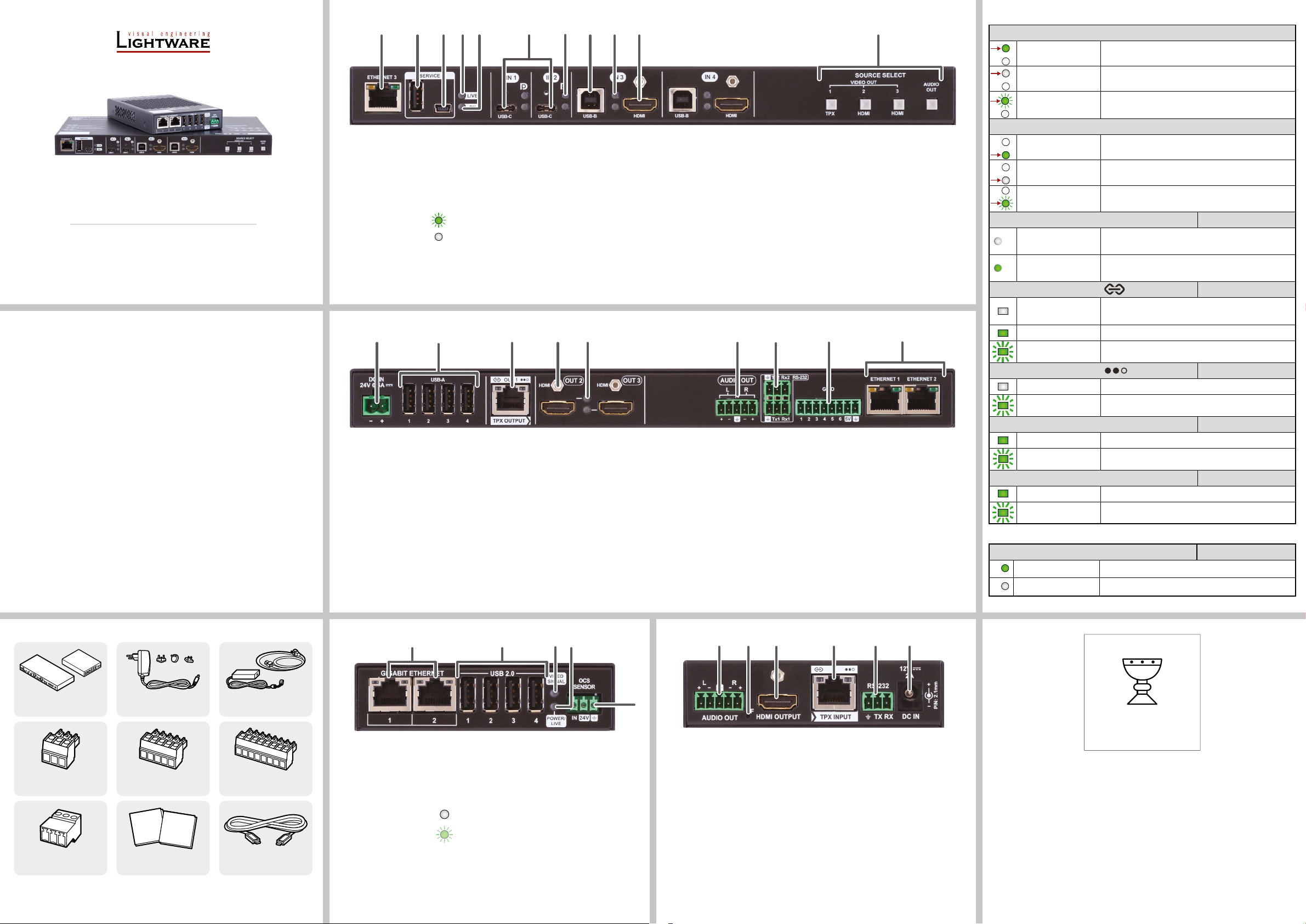
Front view (UCX-TPX-TX20)
1
2 3
4
Status LEDs
Quick Start Guide
UCX-4x3-TPX-TX20
HDMI-UCX-TPX-RX107
Important Safety Instructions
Please read the supplied safety instruction document before using the product and keep it
available for future reference.
Introduction
Lightware’s universal matrix Transmitter switcher exploits the USB-C connectivity for a
simplied extension of up to 100m of 4K video, audio, control signals and power providing
meeting participants with easy host switching, video resolution capabilities up to 4K@60Hz at
4:4:4, as well as comprehensive and secure Ethernet features.
The Receiver extender with AVX technology allows users to extend HDMI 2.0 signals up to
4K60 4:4:4 video resolution through a single CATx cable over distances of up to 100 meters.
They also support independent USB host switching with USB 2.0, making the pair excellent
for meeting room setups.
The Transmitter / Receiver pair is is featured with audio de-embedding function via the 5-pole
®
Combicon analog audio ports.
Phoenix
Beyond the benets of sending high-resolution video over long distances, the pair is also
capable of handling various connectivity standards, including bi-directional RS-232, GPIO and
OCS as well.
The Gigabit Ethernet port is also a valuable addition, allowing users to connect an additional
device to the network directly through the TPX extender.
The Transmitter is also capable of powering the Receiver remotely over Ethernet, as the
Receiver is PoE compatible.
1 2 4 6 8 9 w3 q75
Congurable
1
Ethernet port
USB-A port The SERVICE-labelled USB-A connector is designed for
2
Micro USB port The SERVICE-labelled USB mini-B port is designed for
3
LIVE LED
4
RX LED Function will be implemented in a later release.
5
USB-C ports USB-C port for receiving video and audio signals, as well as
6
Rear view (UCX-TPX-TX20)
RJ45 connector for congurable 1GBase-T Ethernet
communication.
service funtions.
service functions.
blinking The device is powered on and operational.
off The device is not powered or out of operation.
USB data from the host device.
7
8
9
q
w
¢
of a different power source.
1 2 5 6
DC input DC input for local powering. Connect the output to the
1
USB-A ports Downstream ports for connecting USB peripherals (e.g.
2
TPX output port RJ45 connector for AVX output signal transmission.
3
HDMI output ports HDMI output ports for sending video and audio signals to
4
Status LEDs For more information, see the table on the right.
5
2-pole Phoenix connector. For more details, see the
powering options on the next page.
camera, keyboard, multitouch display).
See more details about the connector in the Power
Supply Options and the Status LEDs sections.
the receiver.
6
7
8
9
to supply devices with higher voltage requirements.
Status LEDs For the details, see the table on the right.
USB-B ports Upstream ports for connecting USB host devices (e.g.
computer).
Status LEDs For the details, see the table on the right.
HDMI input
ports
Input selection
buttons
Always use the supplied power supply. Warranty void if damage occurs due to use
Analog Audio
output port
RS-232 ports 3-pole Phoenix® connectors for bi-directional RS-232
GPIO port 8-pole Phoenix® connector for congurable general
Congurable
Ethernet ports
The overall power supply of the USB-A connectors is beyond 1.5A, which makes it possible
HDMI input port for receiving video and audio signals.
For more details on the button functionality, see the table on
the other side. When the LEDs blink green three times after
pressing the button, they show that the front panel lock is
enabled.
7
Audio output port (5-pole Phoenix®) for balanced analog
audio output signal. The signal is de-embedded from the
selected video signal.
communication.
purpose. Max. input/output voltage is 5V, see the details
on the next page.
RJ45 connectors for congurable 1GBase-T Ethernet
communication.
8
93 4
Video Input Status LED (the upper one)
on There is a valid video signal on this port.
off There is no valid video signal on this port.
blink once The port is selected by a button press.
USB Status LED (the lower one)
on The USB Host is connected and selected.
off No USB Host or deselected port.
blink once Port selected by a button press.
VIDEO SIGNAL Transmitter / Receiver
off
on (green)
TPX INPUT/OUTPUT
off
on (green) Connection is established with 10G / 5G / 2.5G bandwith.
blinking (green) Link training is in progress.
TPX INPUT/OUTPUT
off No data transmission on the port.
blinking (green) Data transmission is active.
GIGABIT ETHERNET - LEFT LED Transmitter / Receiver
on (green) Connection is established with 100Mbps bandwith.
blinking (green) Data transmission is active.
GIGABIT ETHERNET - RIGHT LED Transmitter / Receiver
on (green) Connection is established with 1Gbps bandwith.
blinking (green) Data transmission is active.
Rear Panel LEDs
Video Output Status Transmitter
on The video signal is present.
off The signal is not present or muted.
No video signal detected on the HDMI input (TX) or
HDMI output (RX) port.
Video signal is detected on the HDMI input (TX) or HDMI
output (RX) port.
Transmitter / Receiver
No connection is established between the transmitter
and the receiver units.
Transmitter / Receiver
Box Contents
Transmitter / Receiver
device
Phoenix® Combicon
3-pole connector
Phoenix® Combicon
3-pole male connector
1
Only for the HDMI-UCX-TPX-RX107 device.
2
Only for the UCX-4x3-TPX-TX20 device
12V DC adaptor with
interchangeable plugs
Phoenix® Combicon
5-pole connector
Safety and
Warranty
Info
Safety & Warranty Info;
2
Quick Start Guide
Quick
Start
Guide
Front view (HDMI-UCX-TPX-RX107) Rear view (HDMI-UCX-TPX-RX107)
1
2 3
24V power adaptor with
1
2
IEC power cable
Phoenix® Combicon
8-pole connector
Type C (USB-C) to Type C
(USB-C) Cable, 1m
2
Gigabit Ethernet
1
ports
USB-A ports Downstream ports for connecting USB peripherals (e.g.
2
2
2
Video signal LED For more information, see the table on the right.
3
Power/LIVE LED off Device is not powered.
4
OCS sensor 3-pole Phoenix® connector (male) for connecting an
5
The overall power supply of the USB-A connectors is beyond 1.5A, which makes it possible
to supply devices with higher voltage requirements.
1Gbase-T RJ45 connectors for user Ethernet purpose.
camera, keyboard, multitouch display).
blinking between 50% and
100% brightness (green)
occupancy sensor. The port provides 24V output voltage
(50mA).
Device is powered on
and operational.
5
Analog audio
1
output port
Factory reset
2
button
HDMI output port HDMI output ports for connecting sink devices (e.g.
3
TPX input port RJ45 connector for AVX input signal transmission. See
4
RS-232 port 3-pole Phoenix® connector for bi-directional RS-232
5
DC input DC input for local powering. For more details, see the
6
Audio output port (5-pole Phoenix®) for balanced analog
audio output signal. The signal is de-embedded from the
selected video signal.
Hidden button for setting the device to factory default values.
displays).
more details about the connector in the Power Supply
Options and the Status LEDs sections.
communication.
powering options next page.
4
5
6
TAKE CARE OF ME
I AM THE ONE AND ONLY
USER DOCUMENT FOR
THIS PRODUCT
Lightware Visual Engineering PLC.
Budapest, Hungary
[email protected] +36 1 255 3800
[email protected] +36 1 255 3810
©2023 Lightware Visual Engineering. All rights reserved. All trademarks mentioned are the
property of their respective owners. Specications are subject to change without notice.
Further information on the device is available at www.lightware.com.
Doc. ver.: 1.1
19210084
Page 2
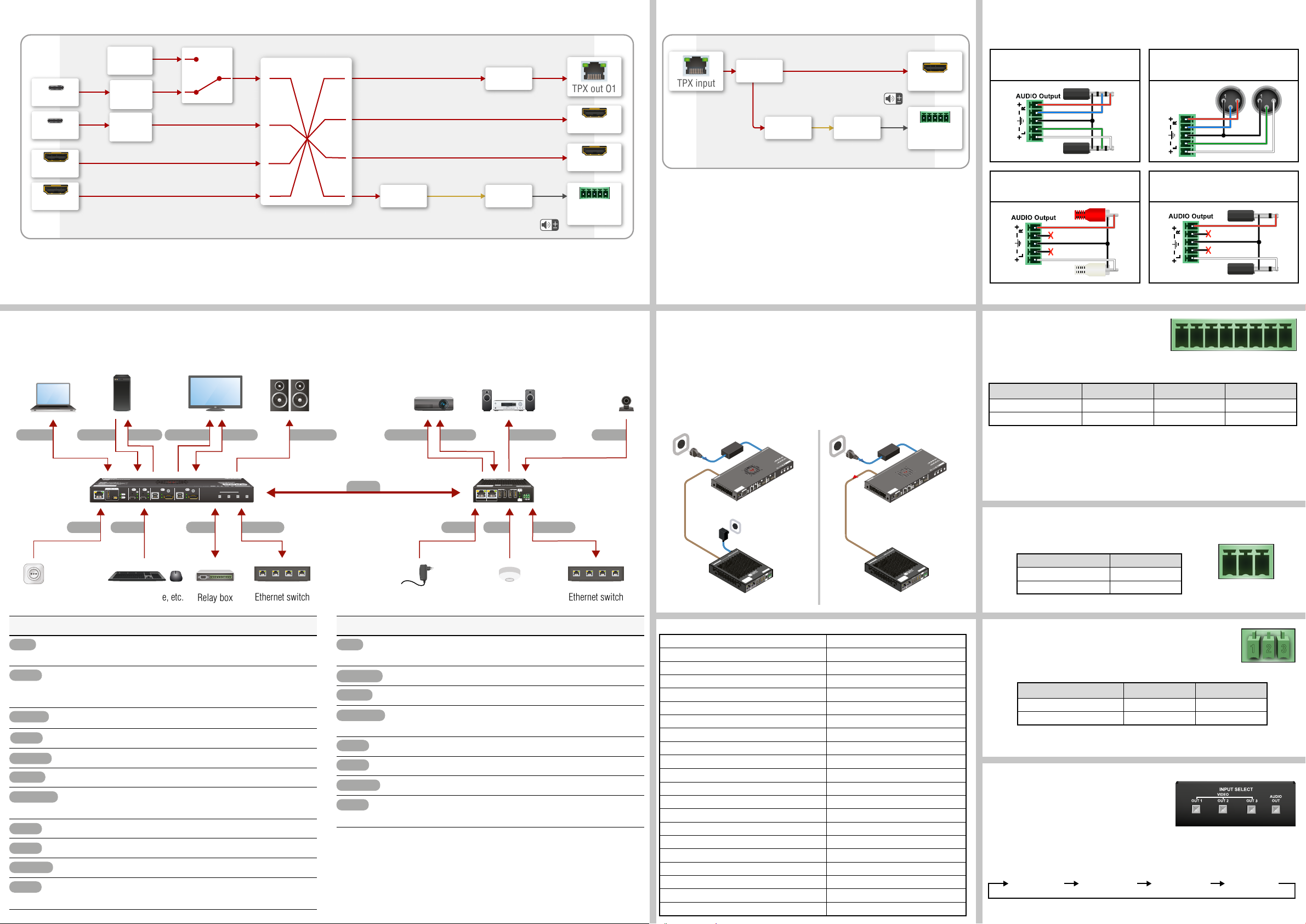
Port diagram for video / audio (UCX-TPX-TX20) Port diagram for video / audio (HDMI-UCX-TPX-RX107)
USB-C IN 1
USB-C IN 2
HDMI IN 3
HDMI IN 4
TPX
USB-C
HDMI in
USB-B
HDMI out
RS-232
Audio out
USB-A
GPIO
Ethernet
Power
TPX
HDMI out
RS-232
Audio out
USB-A
OCS
Ethernet
Power
AUDIO Output
HDMI-UCX-TPX-RX107
24V DC Power adaptor
HDMI-UCX-TPX-RX107
24V DC Power
UCX-4x3-TPX-TX20
Power outlet
Transmitter Side Receiver Side
Power adaptor* OCS sensor
Relay box
2x
4x4 audio/video crosspoint
Digital audio/video
Digital audio/video
Digital audio/video
Audio
de-embedder
De-embedded
audio
IP
packetizer
D/A
converter
IP
packges
Analog
audio
TPX out O1
HDMI out O2
HDMI out O3
Analog audio
out
IP
TPX input HDMI output
de-packetizer
Audio
de-embedder
Digital audio/video
De-embedded
audio
D/A
converter
USB-C in I1
USB-C in I2
HDMI in I3
HDMI in I4
Welcome
screen I5
USB-C to
HDMI
converter
USB-C to
HDMI
converter
Digital audio/video
Digital audio/video
Digital audio/video
Analog
audio
Analog audio
out
Audio Cable Wiring Guide
The Taurus UCX series is built with a 5-pole Phoenix® output connector. See a few examples
below of the most common assembling cases.
Balanced output to balanced input
Phoenix - 2x6.3 (1/4”) TRS
Balanced output to unbalanced input
Phoenix - 2x RCA
Balanced output to balanced input
Phoenix cable - 2x XLR plugs
2
3
2
3
Balanced output to unbalanced input
Phoenix - 2x 6.3 (1/4”) TS
Connecting steps
USB-C
transmitter
4K projector Audio amplifier WebcamActive speakers4K TV4K PCLaptop
2x 2x 4x
Power
USB-B RS-232HDMI in HDMI out
ETHERNET 3
USB-C HDMI USB-B HDMIUSB-BUSB-C
SOURCE SELECT
VIDEO OUT
AUDIO
OUT
3
1
2
HDMI
TPX
HDMI
TPX
Ethernet
RS-232HDMI out USB-A
GIGABIT ETHERNET
Power OCSUSB-A GPIO
USB 2.0
21
1 234
Audio outAudio out
HDMI-UCX-TPX-RX107
OCS
SENSOR
IN
receiver
Ethernet
4x
Keyboard, mouse, etc.
Transmitter Side
Connect a CATx cable between the TPX output port of the transmitter and
the TPX input port of the receiver.
Connect a USB-C source to the USB-C input port. The applied cable
shall be certied for Displayport Alternate mode HBR2 (4x5.4Gbps)
applications.
Connect a source to the HDMI input port of the transmitter by a HDMI cable.
Optionally connect the USB host.
Connect a sink to the HDMI input port of the transmitter by a HDMI cable.
Optionally for RS-232: connect a device to the RS-232 port.
Optionally for analog output: connect an audio device to the analog audio
output port by an audio cable.
Optionally connect USB peripherals to the USB-A ports with USB cables.
Optionally connect a controller/controlled device to the GPIO port.
Optionally connect the device to a LAN network.
Powering on the devices is recommended to do as the nal step during the
installation. Please check the Power Supply Options section for the details.
Ethernet switch
Receiver Side
Connect a CATx cable between the TPX output port of the transmitter and
the TPX input port of the receiver.
Connect the sink to the HDMI output port of the receiver by a HDMI cable.
Optionally for RS-232: connect a device to the RS-232 port.
Optionally for analog output: connect an audio device to the analog audio
output port by an audio cable.
Optionally connect USB peripherals to the USB-A ports with USB cables.
Optionally connect an occupancy sensor to the OCS port.
Connect the device to a LAN network.
Powering on the devices is recommended to do as the nal step during the
installation. Please check the Power Supply Options section for the details.
¢
Only connect one of the devices to the LAN, in order to avoid creating a network
loop!
* Powering via the power adaptor is only necessary if the Receiver is not powered over the
Etherenet by the Transmitter.
Ethernet switch
Powering options
The UCX-4x3-TPX-TX20 is capable of charging a device with 100W over one USB-C port and
another device with 20W over the other USB-C port, or charging with 60W over both ports.
It is also capable of providing the HDMI-UCX-TPX-RX107 device with remote power through
the TPX ports.
The devices can be powered in any of the following ways:
1. Local adaptor for both TX and RX 2. Local adaptor for TX and remote
power to RX
0
2
USB Type-C and HDMI Matrix Transmitter Switcher
HDMI 2.0
RS-232
UCX-4x3-TPX-TX20
CATx
(AVX)
TPX receiver with HDMI connector
USB 2.0 HUB and Host Switch
AUDIO
FRONT LEDs
Input upper
OFF: Video not present on input
ON: Video present on input
Blink once: Port selected by a button press
Input lower
OFF: No USB Host or deselected port
ON: USB Host connected and selected
Blink once: Port selected by a button press
M
D
H
REAR LEDs
HDMI outputs
OFF: Signal not present or muted
ON: Signal present
R
X
P
T
-
X
C
U
I
SERVICE
ETHERNET 3
12V DC
Power
adaptor
7
0
1
X
IN 1
LIVE
USB-C HDMI USB-B
RX
GIGABIT ETHERNET
21
X
T
X
P
T
3
x
4
-
X
C
U
IN 4
IN 3
IN 4
IN 2
Type-C (Only IN1 & IN2)
IN 3
2 x 60W charging power
DP Alt Mode supported
IN 1
IN 2
SOURCE SELECT
VIDEO
IN 1
AUDIO OUT
AUDIO
OUT
SOURCE SELECT
VIDEO OUT
HDMI
Made in EU, Hungary
TPX HDMI
IN 4
HDMIUSB-BUSB-C
IN 3
IN 2
Power
send
USB Type-C and HDMI Matrix Transmitter Switcher
HDMI 2.0
RS-232
USB 2.0 HUB and Host Switch
AUDIO
FRONT LEDs
Input upper
OFF: Video not present on input
ON: Video present on input
Blink once: Port selected by a button press
Input lower
OFF: No USB Host or deselected port
ON: USB Host connected and selected
Blink once: Port selected by a button press
REAR LEDs
HDMI outputs
OFF: Signal not present or muted
ON: Signal present
ETHERNET 3
UCX-4x3-TPX-TX20
0
1
X
R
X
P
T
-
TPX receiver with HDMI connector
X
C
U
I
M
D
H
CATx
Made in EU, Hungary
OCS
SENSOR
VIDEO
SIGNAL
24V
USB 2.0
IN
POWER/
LIVE
4
3
1 2
(AVX)
adaptor
0
2
X
T
-
X
P
T
-
3
x
4
-
X
C
U
IN 4
IN 3
IN 4
IN 2
Type-C (Only IN1 & IN2)
IN 3
2 x 60W charging power
DP Alt Mode supported
IN 1
IN 2
SOURCE SELECT
VIDEO
IN 1
AUDIO OUT
AUDIO
OUT
SOURCE SELECT
VIDEO OUT
HDMI
Made in EU, Hungary
TPX HDMI
IN 4
HDMIUSB-BUSB-C
IN 3
IN 2
IN 1
LIVE
SERVICE
USB-C HDMI USB-B
RX
7
Made in EU, Hungary
OCS
SENSOR
VIDEO
SIGNAL
24V
USB 2.0
IN
POWER/
LIVE
4
3
GIGABIT ETHERNET
1 2
21
Factory default settings
IP address Dynamic (DHCP is enabled)
Hostname lightware-<serialno>
Video Crosspoint setting I1 on O1, I2 on O2, I3 on O3
HDCP mode (in) HDCP 2.2
HDCP mode (out) Auto
Signal type Auto
Emulated EDID F47 - (Universal HDMI with PCM audio)
Audio Crosspoint setting I1 on O4
Analog audio output levels Volume (dB): 0.00; Balance: 0 (center)
Video Autoselect Disabled
USB-C Power Limit 60W / 60W
DP Alternate Mode Policy Auto
Port Power Role Dual Role
USB Autoselect Follow video O1
D1-D4 Power 5V Mode Auto
RS-232 port setting (UCX-4x3-TPX-TX20) 9600 BAUD, 8, N, 1
RS-232 port setting (HDMI-UCX-TPX-RX107) 115200 BAUD, 8, N, 1
RS-232 serial over IP Enabled
HTTP, HTTPS Enabled
HTTP, HTTPS authentication Disabled
LARA Disabled
GPIO (General Purpose Input/Output Ports)
The device has seven GPIO pins that operate at TTL
digital signal levels and can be set to high or low level
(Push-Pull). The direction of the pins can be input or output (adjustable). The signal levels are
the following:
Input voltage (V) Output voltage (V) Max. current (mA)
Logic low level 0 - 0.8 0 - 0.5 30
Logic high level 2 -5 4.5 - 5 18
Plug pin assignment 1-6: Congurable, 7: 5V (max. 500 mA); 8: Ground
The recommended cable for the connectors is the AWG24 (0.2 mm
used ‘alarm cable’ with 4x0.22 mm2 wires.
The maximum total current for the six GPIO pins is 180 mA, the max. supported input/
output voltage is 5V.
1 2 3 4 5 6 7 8
2
diameter) or the generally
RS-232
The switcher provides a 3-pole Phoenix® connector for bi-directional serial communication.
The signal levels are the following:
Output voltage (V)
Logic low level 3 - 15
1 2 3
Logic high level -15 - 3
Plug pin assignment: 1: Ground, 2: TX data, 3: RX data
OCS (Occupancy) Sensor
The switcher is supplied with a 3-pole Phoenix® connector (male), which is
for connecting an OCS sensor.
Plug pin assignment: 1: Congurable; 2: 24V (max. 50 mA); 3: Ground
The signal levels for the Pin 1 Input voltage (V) Max. current (mA)
Logic low level 0 - 0.8 30
Logic high level 2 -5 18
The occupancy sensor connector and the GPIO port are not compatible with each
¢
other because of the voltage level difference, please do not connect them directly.
1 2 3
Button functionality
Push the OUT1 button to set the video input to the
TPX OUT1 port.
Push the OUT2 button to set the video input to the
HDMI OUT2 port.
Push the OUT3 button to set the video input to the HDMI OUT3 port.
Push the AUDIO OUT button to set the audio source of the analog audio output.The sequence
is the following (both for the video and audio switching):
1
2
3
4
 Loading...