

Lightware HDMI-TPS-TX95, HDMI-TPS-RX95, DVI-HDCP-TPS-TX95, DVI-HDCP-TPS-RX95 Quick Start Manual
Page 1
Quick Start Guide
HDMI-TPS-TX95
HDMI-TPS-RX95
DVI-HDCP-TPS-TX95
DVI-HDCP-TPS-RX95
Further information
The User’s manual of this appliance is available at www.lightware.eu.
See the Downloads section on the website of the product.
Contact us
+36 1 255 3800
+36 1 255 3810
Lightware Visual Engineering LLC.
Peterdy 15, Budapest H-1071, Hungary
Doc. ver.: 2.0
19200019
Important safety instructions
Please read and keep the information in the attached safety instructions supplied with the
product before start using the device.
Introduction
The HDMI-TPS-RX/TX95 and DVI-HDCP-TPS-RX/TX95 are DVI 1.0 and HDMI 1.4
compatible long distance-extenders. The difference between HDMI and DVI-HDCP models
is just the HDMI and DVI connector. The units offer bi-directional RS-232, Infra-Red
(IR), and Ethernet signal pass-through on the same CAT5e...CAT7 cable that carries the
uncompressed HDMI video and audio signal.
Box contents
Remote power options
The TPS extenders can be powered remotely by its extender pair or a TPS matrix board. This
feature can be enabled or disabled with jumper settings. Switch off the extenders. Loose the
screws and remove the small plate from the right side of the enclosure. To enable the remote
power function place the jumper block onto all the pinheads. To disable it place the jumper
block onto the upper line pinheads only. In case of enabled remote power on both extenders
the local adaptor can be placed at any side.
The TPS remote powering must be used only with 95 series TPS extenders and MX
TPS matrix boards. Using it with other devices may damage both units.
Do not connect any device to the TPS connector unless you are sure they are compatible! Connecting incompatible devices with similar connectors may cause harm to
the devices.
Never connect any third party device to the extender with remote powering!
AWG 26 cables are not recommended with remote powering (reduce cable distances).
Extender unit 12V DC power adaptor
with interchangeable plugs
Infrared detector unit
(for RX95)
Infrared emitter unit
(for TX95)
Safety and Warranty info,
Quick Start Guide
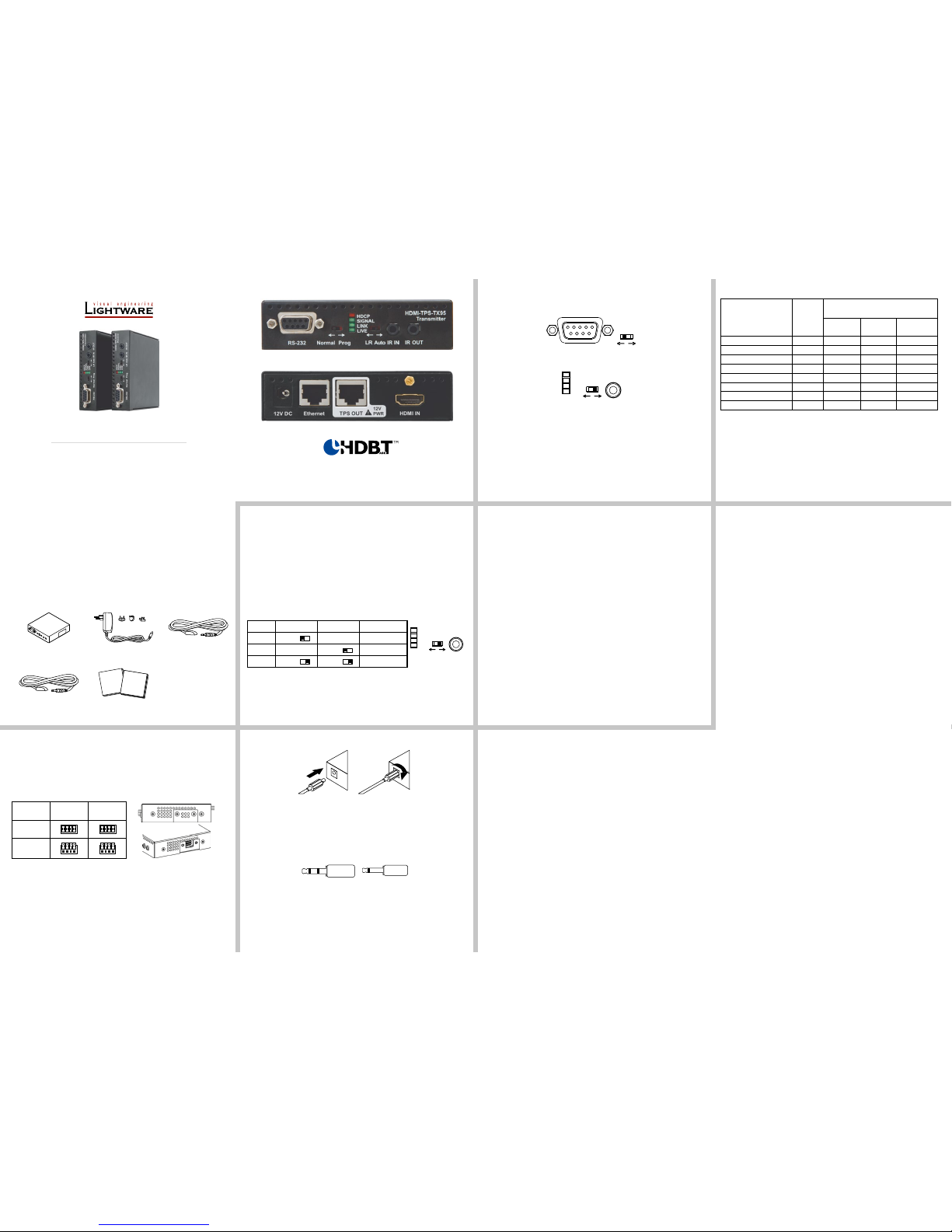
Front view
Rear view
Transmitter and receiver have the same construction and connectors.
The product is compatible with
HDBaseT
TM
and the HDBaseT Alliance logo are trademarks of the HDBaseT Alliance.
Connecting steps – transmitter and receiver
1. Power off all devices. (Installing with powered devices may harm them.)
2. Check the RS-232 switches on the TX and RX; they must be in Normal position.
3. Set the desired TPS link mode with the TPS link mode switch on the front side.
4. Set the desired TX remote power mode with the jumpers on the right side of the TX.
5. Connect a CATx cable to the TPS OUTPUT on the TX.
6. Connect the video source and the desired accessory devices to the TX.
7. Set the desired RX remote power mode with the jumpers on the right side of the RX.
8. Connect the other end of the CATx cable to the TPS INPUT on the RX.
9. Connect the video sink and the desired RS-232, IR and Ethernet devices to the RX.
10. Supply the extenders with 12V 2A DC: rstly connect to the extenders, then secondly
to the AC power socket. If the remote power is enabled on both sides only one local
adaptor can be used, otherwise both units must be powered by local adaptors.
11. Supply the other connected devices.
Locking DC plug
Twist 90° clockwise to lock.
Infra-Red (IR)
One IR emitter and one detector are supplied with the TX and the RX. One emitter and one
detector is enough for controlling only one IR sink device. If there is an IR sink device to be
controlled next to the TX and the other one is next to the RX, two emitter-detector pairs are
needed. The IR emitter and the detector have standard 3.5 mm TRS (jack) connectors. The
emitter’s plug has two poles (mono) and the detector’s one has three poles (stereo).
The second emitter and detector pair can be ordered from Ligtware separately.
IR extension is available only with point-to-point connection of the extenders.
TPS link modes
HDBaseTTM (HDBT): more bandwidth (higher resolutions), shorter CATx cable length. If
no video present, the units change to LPPF mode automatically.
Long reach (LR): Longer CATx cable length, less bandwidth (limited resolution). The
LPPF mode is not available in LR TPS link mode.
Low Power Partial Functionality (LPPF): Only Ethernet, RS-232 and IR are extended.
Toggling between TPS link modes
The extenders have a toggle switch with two states: Auto and LR. If any unit has LR state
both of them switch into LR mode (go into LPPF mode is available only from HDBT mode).
If both units have Auto state and there is valid video signal on the transmitter the common
mode will be HDBT. If the video signal disappears devices go into LPPF mode.
Setting Transmitter Receiver TPS link mode
1 LR don’t care LR
2 don’t care LR LR
3 Auto Auto HDBT / LPPF
If an extender and a TPS matrix board are paired the board forces the extender to use the
settings of the matrix. The extender’s TPS mode switch has no effect.
Always use the Auto mode with third-party devices!
Bi-directional pass-through data lines
The direction of the video extension is xed from TX towards RX but the pass-through data
lines are bi-directional. It means the RS-232, IR, Ethernet source and sink devices can be
connected either to the TX or the RX.
Ethernet
The Ethernet port on the RX or on TX can be connected to a LAN hub, switch or router with
a LAN cable. The other side behaves as an Ethernet uplink port. Extenders support 10/100
Mbit/sec data transfer rate. The direct access is also supported with crosslink cable. The
Ethernet port has auto crossover function. It is able to recognize and handle both cable
types: patch and cross TP cables.
RS-232
Third party devices with standard RS-232 port are supported as the extenders work in „passthrough” mode. TX and RX provide 9-pole D-sub female connector. Use straight-serial cable
to connect a DTE device to an extender and use a cross serial cable in case of pairing a
DCE device to the other TPS extender. The RS-232 options – the baud rate and the parity
bits are set on the third party devices and it can be anything. The extenders support any
kind of serial settings.
Please read the user’s manual of the RS-232 device to get its type. The extenders work
as DCE devices.
Maximum twisted pair distances
Resolution
Pixel
clock rate
Cable lengths
(Auto / Long reach TPS mode)
CAT5e
AWG24
CAT7
AWG26 **
CAT7
AWG23
1024x768@60Hz 65 MHz 100 m / 130 m* 90 m / 120 m* 120 m / 170 m*
1280x720p@60Hz 73.8 MHz 100 m / 130 m* 90 m / 120 m* 120 m / 170 m*
1920x1080p@60Hz (24bpp) 148.5 MHz 100 m / 130 m* 90 m / 120 m* 120 m / 170 m*
1920x1200@60Hz 152.9 MHz 100 m / NA 90 m / NA 120 m / NA
1600x1200@60Hz 162 MHz 100 m / NA 90 m / NA 120 m / NA
1920x1080@60Hz (36bpp) 223 MHz 70 m / NA 70 m / NA 100 m / NA
3840x2160@30Hz UHD 297 MHz 70 m / NA 70 m / NA 100 m / NA
4096x2160@30Hz 4K 297 MHz 70 m / NA 70 m / NA 100 m / NA
* Long reach TPS mode supports pixel clock frequencies up to 148.5 MHz.
** AWG 26 cables are not recommended with remote powering.
Above values are valid when the transmitter is powered by a local adaptor; distances may
decrease depending on the powering mode (local or remote) and cable quality.
CAT7 SFTP AWG23 cable is always recommended.
Front panel LEDs
HDCP
OFF: video output signal is not encrypted with HDCP.
ON: video output signal is encrypted with HDCP.
VIDEO
OFF: no video signal transmission.
ON: video signal transmission.
LINK
OFF: TPS connection failed between the devices.
BLINKING: TPS connection is detected and LPPF link mode is active.
ON: TPS connection is detected and HDBT or LR link mode is active.
LIVE
OFF: no power supply or out of order.
BLINKING: device is powered and ready to use.
TPS link modes
If an extender and a TPS matrix board are paired the board forces the extender to use the
settings of the matrix. The extender’s TPS mode switch has no effect. For detailed information about the TPS link modes in case of matrix boards see the user’s manual of the matrix.
Installation of the extender with a matrix
1. Power off all devices. (Installing with powered devices may harm them.)
2. Check the RS-232 switch(es) on the extender(s); they must be in Normal position.
3. The state of the TPS link mode switch makes no difference on the extender because the
connected board forces the extender to use the settings of the matrix.
4. Set the remote power mode of the matrix boards with the jumpers on them. Every port
can be set for remote powering separately. To enable the remote power function place
the jumper block onto all the pinheads of the desired port. To disable it remove the jumper
block. For detailed information, see the user’s manual of the matrix.
5. Set the extenders’ remote power mode with the same method as it mentioned in the
standalone case.
6. Pair the extender(s) and the matrix board(s) with CATx cable(s). The transmitters’ TPS
OUT with the input boards’ TPS IN and the receivers’ TPS IN with the output boards’
TPS OUT.
7. Connect the video source(s), sink(s) and the desired accessory device(s) to the matrix
(MX-TPS boards don’t support the IR pass-through).
8. Connect the video source(s), sink(s) and the desired accessory device(s) to the extenders.
9. Supply that matrix boards with 12V 6,67A DC which have ports with enabled remote
powering.
10. Supply the extenders with 12V 2A DC. If the remote power is disabled on the connected
matrix card’s port, local adaptor must be used for the extender.
11. Connect the power cord of the matrix into the outlet and switch on the matrix.
12. Supply the other connected units.
3 pole, 2 ring
IR receiver
2 pole, 1 ring
IR transmitter
Safety and
warranty
info
Quick
Start
Guide
TX side RX side
Enabled
Disabled
(default)
RS-232 Normal
Prog
RS-232
IR IN
LR
Auto
SIGNAL
LIVE
LINK
HDCP
IR IN
LR
Auto
SIGNAL
LIVE
LINK
HDCP
Page 2
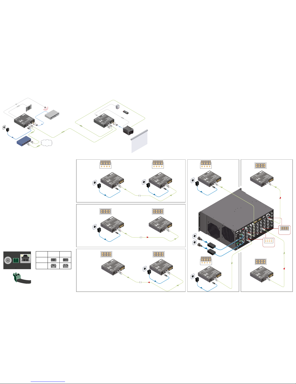
Typical standalone application – the transmitter and the receiver
Remote power options
The TPS extender can be powered remotely by the connected TPS matrix board or its
extender pair. This feature of the board can be enabled or disabled with jumper settings
for every port separately. Switch off the matrix. Remove the desired cards. Pinheads are
behind of the TPS connectors. To enable the remote powering function of the port place
the jumper block onto all the corresponding pinheads. Connect the external 12V DC 6,67A
power adaptor to the card separately. Finally, set the extenders’ desired power modes.
To disable the remote powering function for a port remove the jumper block from the
corresponding pinheads.
Jumper settings
Place the jumper blocks onto all the pinheads of those units which you want to be powered
remotely. For disabling the remote powering remove the jumper blocks and place them
onto the upper line pinheads only.
Legend
(A) Standalone with local powering
(B) Standalone with remote powering for RX
(C) Standalone with remote powering for TX
(D) Integrated with local powering
(E) Integrated with remote powering for RX and TX.
TX side RX side
Enabled
Disabled
(default)
Read carefully all the detailed instructions about remote powering devices! Never
use remote powering with third-party units!
AWG 26 cables are not recommended with remote powering (reduce cable distances).
For detailed instruction read the user’s manual of the MX-TPS cards.
The PSU-12VP power supply adaptor is an optional accessory and can be ordered
separately.
MX-TPS-OB-S
8 CH TPS OUTP UT BOARD W
Ethernet
DC IN
12V 4A
- +
When remote power is enabled, 12V present on TPS connector.
Check compability before connecting devices.
For best performance use CAT6 or CAT7 SFTP cable
HDMI
MX-TPS-IB-S
12V 3A
DC IN
8 CH TPS INPUT BOARD
12V power on TPS connector. Only use with compatible devices!
TPS IN 1 TPS IN 2 TPS IN 3 TPS IN 4 TPS IN 5 TPS IN 6 TPS IN 7 TPS IN 8
MX-TPS-IB-S
12V 3A
DC IN
8 CH TPS INPUT BOARD
12V power on TPS connector. Only use with compatible devices!
TPS IN 1 TPS IN 2 TPS IN 3 TPS IN 4 TPS IN 5 TPS IN 6 TPS IN 7 TPS IN 8
MX-TPS-OB
12V 4A
DC IN
8 CH TPS OUTPUT BOARD
12V power on TPS connector. Only use with compatible devices!
TPS OUT 1 TPS OUT 2 TPS OUT 3 TPS OUT 4 TPS OUT 5 TPS OUT 6 TPS OUT 7 TPS OUT 8
MX-TPS-OB
12V 4A
DC IN
8 CH TPS OUTPUT BOARD
12V power on TPS connector. Only use with compatible devices!
TPS OUT 1 TPS OUT 2 TPS OUT 3 TPS OUT 4 TPS OUT 5 TPS OUT 6 TPS OUT 7 TPS OUT 8
No power send
B
C
D
E
12V DC
Power adaptor
HDMITPS-TX95
Ethernet switch Internet
Touch panel
Blu-ray or DVD Player
LAN
LAN
LAN
TPS connection
CATx up to 170 m
Serial
cable
IR cable
IR emitter
HDMI-HDMI
cable
Projection screen
IR detector
HD Projector
HDMI-TPS-RX95
Remote powered
Serial cable
IR cable
HDMI-HDMI
cable
DVI-HDCP-
TPS-TX95
CATx
A
12V DC
Power adaptor
Disabled
(Local)
Disabled
(Local)
12V DC
Power adaptor
DVI-HDCPTPS-TX95
DVI-HDCPTPS-RX95
Power send
CATx
12V DC
Power adaptor
Enabled Enabled
DVI-HDCPTPS-TX95
DVI-HDCPTPS-RX95
Power send
CATx
12V DC
Power adaptor
Enabled Enabled
DVI-HDCP-TPS-TX95
DVI-HDCPTPS-RX95
Disabled
(Local)
DVI-HDCPTPS-RX95
12V DC
Power
adaptor
CATx
No power send
Disabled
(Local)
12V DC
Power
adaptor
No power
send
CATx
DVI-HDCP-TPS-TX95
Power send
Enabled
CATx
Disabled
Enabled
Power send
DVI-HDCP-TPS-RX95
CATx
Enabled
 Loading...