

Page 1
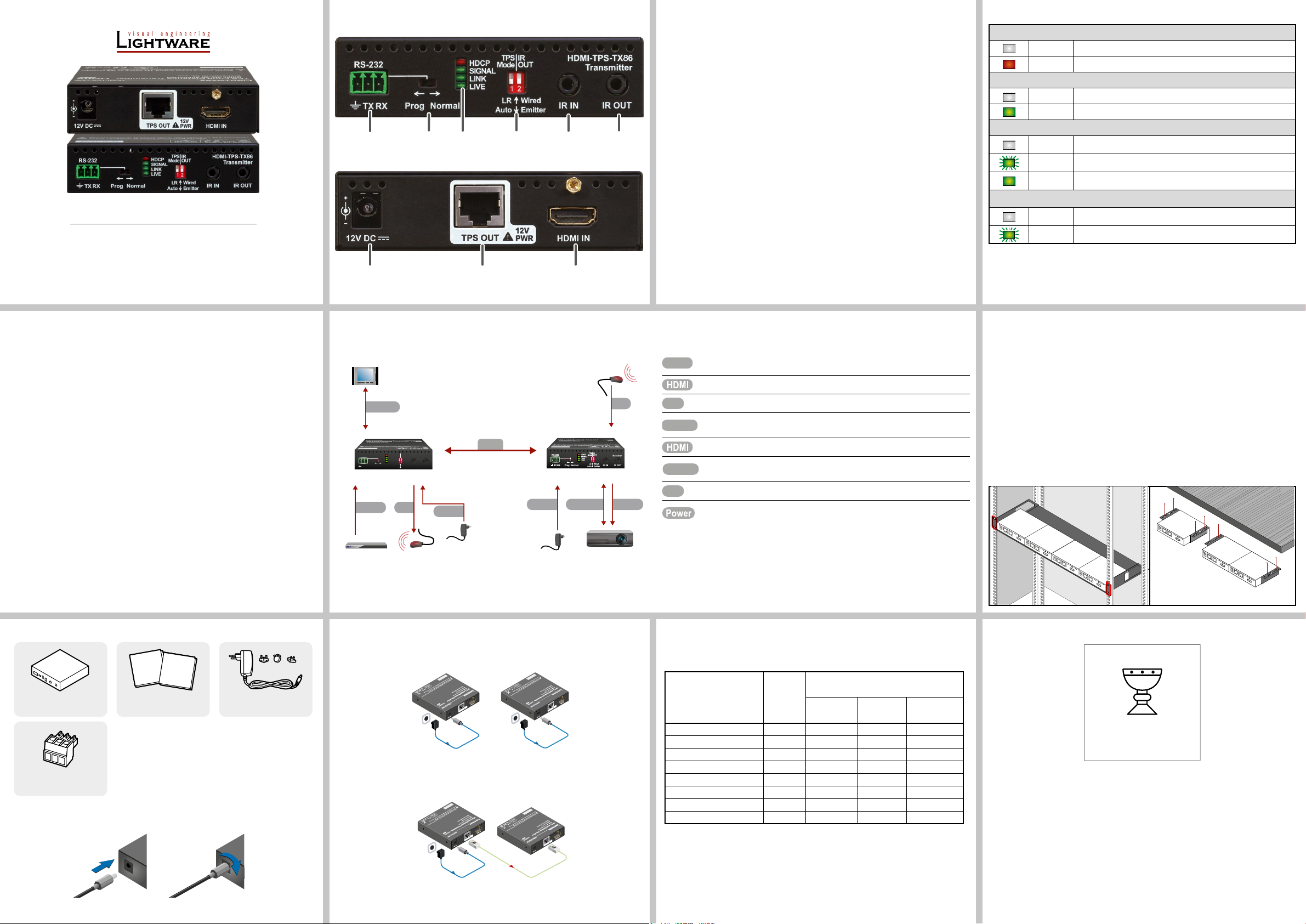
Front and Rear View (HDMI-TPS-TX86)
CATx
IR
RS-232
RS-232
IR
7
8
9
1 2 4 53 6
adaptor
adaptor
Touch panel
IR detector
Front and Rear View Legend (HDMI-TPS-TX86)
Status LEDs
Quick Start Guide
HDMI-TPS-TX86
HDMI-TPS-RX86
Important Safety Instructions
Please read the supplied safety instruction document before using the product and keep it
available for future reference.
Introduction
HDMI-TPS-TX86 and -RX86 twisted pair HDBaseTTM extenders provide extension of
uncompressed 4K/UHD video with embedded audio for long distances over a single CATx cable.
The extender offers uni-directional RS-232 and IR pass-through on the same CATx cable that
carries the video signal. The TPS extenders support full HDCP and EDID compliance and work
on all standard AV resolutions and also 120 Hz 3D signals. 12V remote powering is available
through the single CATx cable, but a local power supply can also be used.
Compatible Devices
It is not recommended to be used with third-party HDBaseTTM devices due to the special
remote powering feature of the device.
Connecting Steps
RS-232
TPS
IR
HDCP
RS-232
TX RX
HDMI- TPS-TX86
HDMI
OUT
Mode
SIGNAL
LINK
LIVE
Wired
LR
NormalProg
Auto Emitter
IR
HDMI-TPS-TX86
IR IN
Transmitter
IR OUT
Power
CATx
Power
HDMI-TPS-RX86
HDMI- TPS-RX86
RS-232
IR
HDMI
RS-232 port Local RS-232 port for bi-directional serial data connection and
1
RS-232 switch Normal: serial data is passed through the device.
2
performing rmware update (programming).
Prog: RS-232 pass-through function is disabled, the device is
ready for the rmware update.
Status LEDs See the next section.
3
TPS mode
4
switch
IR mode
4
switch
IR input IR signal input connector (for 3.5 mm Jack, 3-pole, TRS plug).
5
IR output IR signal output connector (for 3.5 mm Jack, 2-pole, TS plug).
6
DC input 12V DC input for local power supply.
7
TPS port TPS port to the other compatible device (extender/ matrix /board).
8
LR: Long reach TPS mode; lower resolution (max 1080p),
longer distances; Auto: TPS mode is determined automatically.
IR output signal modulation switch; the 38 kHz modulation can
be switched On (Emitter position) or Off (Wired position).
Remote power is always enabled, 12V present on TPS
connector. Check the compatibility before connecting devices.
HDMI port Video port for HDMI signal.
9
Connect the TPS output port of the Transmitter to the TPS input port of the
Receiver by a CATx cable.
Connect a source to the HDMI (DVI-D) input port of the transmitter.
Connect an IR emitter unit to the IR output port of the transmitter.
Connect a controller device to the local RS-232 port of the transmitter.
Make sure the RS-232 switch is in Normal position.
Connect a sink device to the HDMI (DVI-D) output port of the receiver.
Connect a serial cable between the sink device and the RS-232 port of the
receiver.
Connect an IR detector unit to the IR input port of the receiver.
First connect the power adaptor to the DC input of the power injector, then to
the AC power socket.
HDCP
OFF Video output signal is not encrypted with HDCP.
ON Video output signal is encrypted with HDCP.
SIGNAL
OFF No video signal transmission.
ON Video signal transmission.
LINK
OFF TPS connection failed between the devices.
BLINKING TPS connection is detected and LPPF link mode is active.
ON TPS connection is detected and HDBT or LR link mode is active.
LIVE
OFF No power supply or out of order.
BLINKING Device is powered and ready to use.
Mounting the Device (with optionally available accessories)
Under Desk Mounting Kit (UD-kit): to mount one extender under any at surface
(e.g. furniture)
UD Mounting Kit Double (UD-kit double): to mount two extenders under any at surface
(e.g. furniture).
Rack Shelf: 1U high rack shelf provides mounting holes for the fastening of up to four
extenders
Always use the xing screws that are supplied with the mounting accessory. If you
insert screws longer than 6 mm, the device can be damaged.
1. Unplug all the cables connected to the device(s).
2. Turn the device(s) upside down.
3. Put the shelf upside down on the device(s). Position it to get the mounting holes aligned.
4. Fasten the device on the shelf with the provided screws.
5. Fix the shelf to the desired place (screws are not supplied).
Box Contents
Quick
Safety and
Start
Warranty
Guide
Info
Extender unit Safety and Warranty info,
Quick Start Guide
12V DC adaptor with
interchangeable plugs
Phoenix combicon
3-pole connector
Locking DC Plug
Twist 90° clockwise to lock.
Power
Blu-ray player IR emitter
adaptor
Power adaptor
Projector
Power Supply Options
The extenders can be powered by any of the following ways:
1. Local adaptor: 12V DC input for local power supply.
12V DC
Power
2. Remote power: The extender pair can power each other when one of them is locally
supplied with 12V DC adaptor. The extender sends remote power via the TPS IN (on the
receiver) or the TPS OUT (on the transmitter) RJ45 connector to other device.
12V DC
Power
Carefully read all the detailed instructions about remote powering devices! Never
use remote powering with third-party units!
12V DC
Power
adaptor
CATx (TPS)
Power send
Infrared emitter and detector units are optionally available accessories.
Maximum Extension Distances
The values below are valid when the transmitter is powered by a local adaptor; distances may
decrease depending on the powering mode (local or remote) and cable quality.
Cable lengths
Resolution
1024x768@60Hz 65 MHz 100 m / 130 m* 90 m / 120 m* 120 m / 170 m*
1280x720p@60Hz 73.8 MHz 100 m / 130 m* 90 m / 120 m* 120 m / 170 m*
1920x1080p@60Hz (24bpp) 148.5 MHz 100 m / 130 m* 90 m / 120 m* 120 m / 170 m*
1920x1200@60Hz 152.9 MHz 100 m / NA 90 m / NA 120 m / NA
1600x1200@60Hz 162 MHz 100 m / NA 90 m / NA 120 m / NA
1920x1080@60Hz (36bpp) 222.75 MHz 70 m / NA 70 m / NA 120 m / NA
3840x2160@30Hz UHD ** 297 MHz 70 m / NA 70 m / NA 100 m / NA
4096x2160@30Hz 4K ** 297 MHz 70 m / NA 70 m / NA 100 m / NA
Pixel
clock rate
(Auto / Long reach TPS mode)
CAT5e
AWG24
CAT7
AWG26
* Long reach TPS mode supports pixel clock frequencies up to 148.5 MHz.
CAT7 SFTP AWG23 cable is always recommended.
CAT7
AWG23
TAKE CARE OF ME
I AM THE ONE AND ONLY
USER DOCUMENT FOR
THIS PRODUCT
Lightware Visual Engineering PLC.
Budapest, Hungary
[email protected] +36 1 255 3800
[email protected] +36 1 255 3810
©2023 Lightware Visual Engineering. All rights reserved. All trademarks mentioned are the
property of their respective owners. Specications are subject to change without notice.
Further information on the device is available at www.lightware.com.
Doc. ver.: 1.3
19210096
Page 2
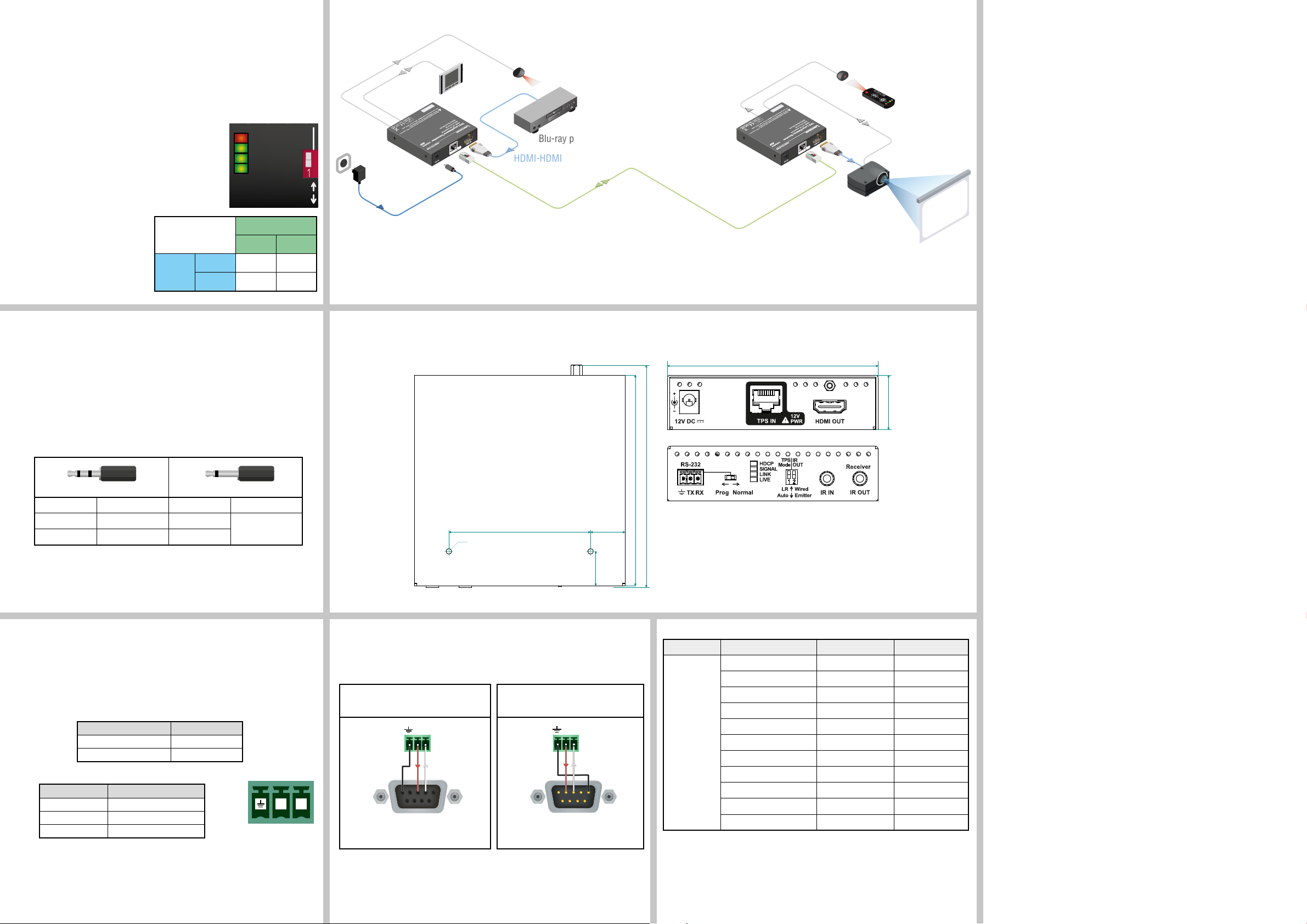
TPS Link Modes
1 2 3
1 2-3
100.4
TX RX
5: Ground
TX RX
5: Ground
The TPS working mode between the transmitter and the receiver parties is determined by the
mode set in them. Both parties inuence the setting that determines the nal TPS transmission
mode. The following TPS modes are dened:
Long reach (LR): Longer CATx cable length, less bandwidth (limited resolution). The
LPPF mode is not available in LR TPS link mode.
HDBaseTTM (HDBT): more bandwidth (higher resolutions), shorter CATx cable length. If
no video is present, the units change to LPPF mode automatically.
Low Power Partial Functionality (LPPF): Only RS-232 and IR are extended.
Toggling Between TPS Link Modes
The toggle switch on the extenders can be used to toggle between
the LR and Auto TPS modes. If both units have Auto state and there
is valid video signal on the transmitter, the common mode will be
HDBT. If the video signal disappears, devices go into LPPF mode.
TPS mode between an extender and a port of a matrix
board
If an extender and a TPS matrix board
are paired, the board forces the extender
to use the settings of the matrix. The
extender’s TPS mode switch has no effect.
Always use the Auto mode with
third-party devices!
The negotiated
TPS working mode
Selected
LR LR LR
mode
(TX)
Auto LR HDBT
HDCP
SIGNAL
LINK
LIVE
Selected mode (RX)
LR Auto
TPS
Mode
LR
Auto
Application diagram
IR cable
Serial cable
HDMITPS-TX86
12V DC
Power adaptor
Touch panel
IR emitter
Blu-ray player
HDMI-HDMI
cable
TPS connection CATx
cable up to 170m
IR cable
HDMITPS-RX86
IR detector
Serial cable
Specication
General
Compliance .................................................................................................... CE, UKCA
EMC (Emission) .....................................................................EN 55032:2015+A1:2020
EMC (Immunity) ...................................................................EN 55035:2017+A11:2020
Electrical safety .................................................................................. EN 62368-1:2020
RoHS .....................................................................................................EN 63000:2018
Operating temperature ...................................................0° to +50°C (+32° to +122°F)
Operating humidity ......................................................... 10% to 90%, non-condensing
Cooling ................................................................................................................passive
Power
Power supply ..................................... external power adaptor / remote power via TPS
Power adaptor ........................... Input 100-240 V AC 50/60 Hz, Output 12V DC, 2.5 A
Power consumption (TX) ................................................................................................
............................. 3.6 W (no signal) / 4.5 W (max. signal) / 13 W (with remote power)
Power consumption (RX) ...............................................................................................
.......................... 5.5 W (no signal) / 6.5 W (max. signal) / 12.3 W (with remote power)
Enclosure
Enclosure material ........................................................................................ 1 mm steel
Bi-directional Pass-through Data Lines
The direction of the video extension is xed from TX towards RX, but the pass-through data
lines are bi-directional. It means the RS-232 and IR source and sink devices can be connected
either to the TX or the RX.
Infra-Red (IR)
One emitter and one detector is enough for remote controlling one IR sink device. If there is an IR
sink device to be controlled next to the TX and the other one is next to the RX, two emitter- detector
pairs are needed. The IR emitter and the detector have standard 3.5 mm TRS (jack) connectors.
The emitter’s plug has two poles (mono) and the detector’s plug has three poles (stereo).
Detector – 3-pole-TRS Emitter – 2-pole-TS
1 Tip Signal (active low) 1 Tip +5V
2 Ring GND 2 Ring
3 Sleeve +5V 3 Sleeve
IR extension is available only with point-to-point connection of the extenders.
Signal (active low)
RS-232
Third-party devices with standard RS-232 port are supported, as the extenders work in passthrough mode. TX and RX provide a 3-pole Phoenix connector. Use straight-serial cable to connect
a DTE device to an extender and use a cross serial cable in case of pairing a DCE device to the
other TPS extender. The RS-232 options – the baud rate and the parity bits – are set on the third
party devices and they can be anything. The extenders support any kind of serial settings.
The signal levels are the following:
Output voltage (V)
Logic low level 3 - 15
Logic high level -15 - 3
RS-232 connector and plug pin assignment
Pin nr. Signal
1 Ground
2 TX data
3 RX data
2 3
Mechanical Drawings (HDMI-TPS-RX86)
Dimensions are in mm. Both the transmitter and the receiver have the same sized enclosure.
106
100.4
67.5 16.4
M3
16.4
Wiring Guide for RS-232 Data Transmission
HDMI-TPS-86 series are built with a 3-pole Phoenix connector. See the examples below
of connecting to a DCE (Data Circuit-terminating Equipment) or a DTE (Data Terminal
Equipment) type device:
Lightware device and a DCE
D-SUB 9 - Phoenix
5
9
2: TX data
3: RX data
1
6
Lightware device and a DTE
D-SUB 9 - Phoenix
1
6
2: RX data
3: TX data
5
9
26
HDMI-TPS-RX86
Video and Remote Powering Compatibility Table
This device Remote device Video / HDBaseTTMRemote Powering
’90 series TPS extender Not recommended Not compatible
’96 series TPS extender Compatible Available
’95 series TPS extender Compatible Available
’97 series TPS extender Compatible none
Other TPS extender Compatible none
TPS ’86 series
MX-TPS IB / OB Compatible With external PSU
MX-TPS2 IB / OB Compatible none
MX-TPS2 IB / OB -P Compatible none
25G TPS IO boards Compatible none
MMX TPS series Compatible none
Third-party HDBaseT
TM
Not recommended Not compatible
Dimensions in mm ............................................................... 100.4 W x 100x4 D x 26 H
Weight (TX) ............................................................................................................287 g
Weight (RX) ...........................................................................................................300 g
Connectors
TX input, RX output ..............................................................................HDMI connector
TX output, RX input ......................................................................RJ45 (TPS interface)
IR input, output ................................................................ 3.5 mm (1.8”) jack connector
Serial port ...............................................................................3-pole Phoenix connector
Power ..............................................................locking DC connector (2.1 / 5.5 mm pin)
Digital Video Signal
Supported signals ............................................................................. DVI 1.0, HDMI 1.4
Signal standard .................. DVI and HDMI standard which supports embedded audio
Supported resolutions .........................................................1920x1080@120 Hz, 24 bit
..................................................up to 4K / UHD (30Hz RGB 4:4:4, 60Hz YCbCr 4:2:0)
3D support ................................................................................................................ yes
HDCP compliant ....................................................................................................... yes
Control over CEC .........................................................................................transparent
EDID support ................................................................................................transparent
Cable length HDMI input port (1080p) ..........................................................max. 20 m
Equalization .................................................................................... adaptive, automatic
TPS port (HDBaseTTM-compatible)
RS-232 pass-through ............................................................................................... yes
IR pass-through ........................................................................................................ yes
Please read the user’s manual of the RS-232 device to get its type. The extenders operate
as a DCE unit according to its pin-out.
For more information about the cable wiring, see the Cable Wiring Guide on our website.
 Loading...