

Lightware HDMI20-OPTC-TX220-Pro, HDMI20-OPTC-RX220-Pro, HDMI20-OPTC-TX220-Pro,HDMI20-OPTC-RX220-Pro Quick Start Manual
Page 1
Quick Start Guide
HDMI20-OPTC-TX220-Pro
HDMI20-OPTC-RX220-Pro
Further information
The document is valid with the following rmware version: 1.0.1
The product brief and further information of this appliance is available on www.lightware.com.
See the Downloads section on the website of the product.
Contact us
+36 1 255 3800
+36 1 255 3810
Lightware Visual Engineering LLC.
Peterdy 15, Budapest H-1071, Hungary
Doc. ver.: 1.1
19200078
Important Safety Instructions
Please read and keep the information in the attached safety instructions supplied with the
product before you start using the device.
The extenders are Class 3R laser products. Caution! Invisible Class 3R laser
radiation! Avoid exposure to the beam!
Introduction
Thank You for choosing Lightware HDMI20-OPTC series devices. The
HDMI20-OPTC-TX/RX220-Pro is a HDMI 2.0 compatible extender pair for video, embedded
audio, RS-232 and Gigabit Ethernet signals, supporting uncompressed 4K UHD resolution
at 60Hz 4:4:4. This extender pair is particularly recommended for rental and staging
applications, 4K live events, and for future-proof operation centers.
According to the philosophy of Lightware’s optical extenders, the transmitter and the receiver
operate in pairs, so the transmitter is designed with LCD screen and jog dial control knob.
This is for controlling the transmitter itself but it also controls and is able to congure the
receiver.
Box Contents
1
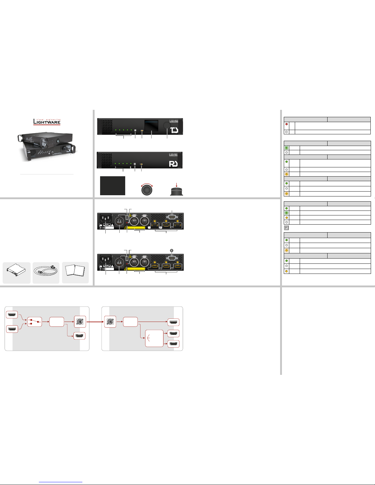
Status LEDs The LEDs give feedback about the current stat,
connections and certain settings of the unit. For details
see front panel’s LEDs in the next section.
2
TX: Select button
RX: Function button
Select button toggles between the Input 1 and the Input 2.
Function button sets the output conversion mode. See
the details below.
3
USB Port USB mini-B port for controlling the unit locally by
Lightware Device Controller software.
4
TX: LCD display Display of the front panel menu.
5
TX: Jog dial knob Browse the menu by turning the knob, click on the
desired item to check or change it.
Front View - HDMI20-OPTC-TX220-Pro
Rear View - HDMI20-OPTC-TX220-Pro
1
AC connector
Standard IEC connector accepting 100-240 V, 50 or 60 Hz.
2
Fiber connector
Neutrik opticalCON DUO LC connector for optical data
transmission. The channel A carries the signal from the
transmitter to channel B in the receiver.
3
Boot button
Hidden button for special bootload function.
4
Break-out connector
The break-out LC connector is internally connected to the
channel B of Neutrik connector in the transmitter and the
channel A in the receiver. It is to carry any optical signal
from the break-out LC connector.
5
Laser LED
It gives feedback about the operation of the optical module. When
the laser is active (laser LED is ON), it radiates invisible waves
from the optical connector. Avoid eye exposure to the beam!
6
LAN
Two Neutrik etherCON connectors for Gigabit Ethernet (to
control the unit or for pass-through). Both are in the same
local network. Remote powering (PoE) is not possible.
7
TX: HDMI connector
RX: HDMI connector
Two HDMI 2.0 input ports and one HDMI 2.0 output port
for local display.
Three HDMI video output ports. Output signal depends on
the output conversion setting, see the details below.
8
Serial port
D-SUB connector for bi-directional RS-232 communication
(control/command injection/pass-through mode).
IEC power connector
Safety and Warranty Info,
Quick Start Guide
Safety and
Warranty
Info
Quick
Start
Guide
Transmitter Side
The video signal is received at the Input 1 or the Input 2. The HDMI splitter duplicates the
signal and sends the same HDMI stream to the local HDMI output and the ber output.
Receiver Side
The video signal arrives via optical cable into the HDMI splitter. It duplicates HDMI stream
and transmits the signal without modifying it to the HDMI Out 2 port. The HDMI splitter
transmits the same signal into the video converter where three output conversion modes can
be set. It species how to deal with the HDMI 2.0 signal and what would be the output video
signal on the Out 1A and the Out 1B.
In Transparent mode (no conversion mode), the video signal is transmitted to the HDMI
Output 1A and the HDMI Output 1B without any changing.
Maximal data transmission capacity of Output 1B is 9 Gbps, if the video signal is above this
bandwidth, there will be no picture on the display.
Split mode means splitting of the original video signal into left and right halves and sending the
split signal to the HDMI Output 1A and the HDMI Output 1B.
In Downsample convert mode (convert to YCbCr 4:2:0) the video converter subsamples the
4:4:4 signal to 4:2:0 on the 1A and 1B Output port.
Port Diagram - Video Concept
LCD Menu and Navigation
The front panel has a color LCD showing the most important settings and parameters. The jog
dial control knob can be used to navigate between the menu items or change the value of a
parameter (both the transmitter and the receiver). The knob can be pressed to enter a menu
or edit/set a parameter.
Front View Legend
Rear View Legend
Rear View - HDMI20-OPTC-RX220-Pro
Transmitter / Receiver
unit
Rear Panel’s LEDs
Laser active Transmitter / Receiver
on It gives feedback about the operation of the optical module, that means the laser
radiates invisible waves. Avoid direct eye contact with the optical connectors!
off Laser module is not active.
Front Panel’s LEDs
Power / LIVE Transmitter / Receiver
blinking The transmitter unit is powered and ready to use.
off The transmitter unit is NOT powered or out of operation.
Fiber link Transmitter / Receiver
on The connection is established between the transmitter and the receiver
and they can communicate to each other.
off When the TX and RX are not connected.
blinking It shows connection error in the RX and TX.
HDCP Transmitter / Receiver
on Video signal is HDCP-encrypted.
off There is no HDCP encryption in the video signal.
blinking It shows HDCP error.
Input 1, Input 2 Transmitter
on This port is selected and there is a valid video signal on it.
blinking When the port is selected and there is no valid video signal on it.
on When the port is not selected, but there is a valid video signal on it.
off This port is not selected and there is no signal on it.
Select button is for switching between Input 1 and Input 2.
Signal present Receiver
on Valid video signal is present.
off No video signal is present.
blinking It shows error in the video signal transmission.
Output conversion Receiver
on Split mode is active.
off Transparent mode (no conversion) is active.
on Downsample convert mode (convert to YCbCr 4:2:0) is active.
MAIN MENU
> System Settings
Ports
EDID
Health
Remote
Menu navigation
& change parameter
Menu selection
& set parameter
Press
Turn
GIGABIT
ETHERNET 1
GIGABIT
ETHERNET 2
RS-232
HDMI 2.0
2
( )
18G
INPUT
HDMI 2.0
1
( )
18G
INPUT
BOOT
A: FIBER OUTPUT
B
LASER
ACTIVE
CAUTION - CLASS 3R INVISIBLE RADIATION
WHEN OPEN AVOID DIRECT EYE EXPOSURE
0.3-0.1A
100-240 V
Sn:
Made in EU, Hungary
HDMI 2.0
( )
18G
50/60 Hz
AC
OUTPUT
1
2
3
6
7
84 5
MAIN MENU
> System Settings
Ports
EDID
Health
Remote
POWER / LIVE
FIBER LINK
HDCP
INPUT 1
INPUT 2
CONTROL
SELECT
USB
HDMI20
OPTC
220-PRO
HDMI20-OPTC-TX220-Pro
HDMI 2.0 Multimode Fiber Transmitter
1
3 4
5
2
INPUT 1
INPUT 2
HDMI Splitter
OUTPUT 2.
Fiber OUT
OUTPUT 2
B
A
OUTPUT 1A
Fiber IN
HDMI Splitter
OUTPUT 1B
Transparent
Split
Downsample
Video Converter
HDMI20-OPTC-TX220-Pro
HDMI20-OPTC-RX220-Pro
B
A
Front View - HDMI20-OPTC-RX220-Pro
HDMI20-OPTC-RX220-Pro
HDMI 2.0 Multimode Fiber Receiver
POWER / LIVE
FIBER LINK
HDCP
SIGNAL PRESENT
OUTPUT CONVERSION
CONTROL
FUNCTION
USB
HDMI20
OPTC
220-PRO
1 32
GIGABIT
ETHERNET 1
GIGABIT
ETHERNET 2
RS-232
HDMI 2.0
1B
(9G)
OUTPUT
HDMI 2.0
1A
(9G/18G)
OUTPUT
BOOT
B: FIBER OUTPUT
A
LASER
ACTIVE
CAUTION - CLASS 3R INVISIBLE RADIATION
WHEN OPEN AVOID DIRECT EYE EXPOSURE
0.3-0.1A
100-240 V
Sn:
Made in EU, Hungary
HDMI 2.0
2
( )
18G
OUTPUT
50/60 Hz
AC
1
2
3
6
7
4 5
8
Transmitter / Receiver
unit
Page 2
Application of Brake-Out Connector
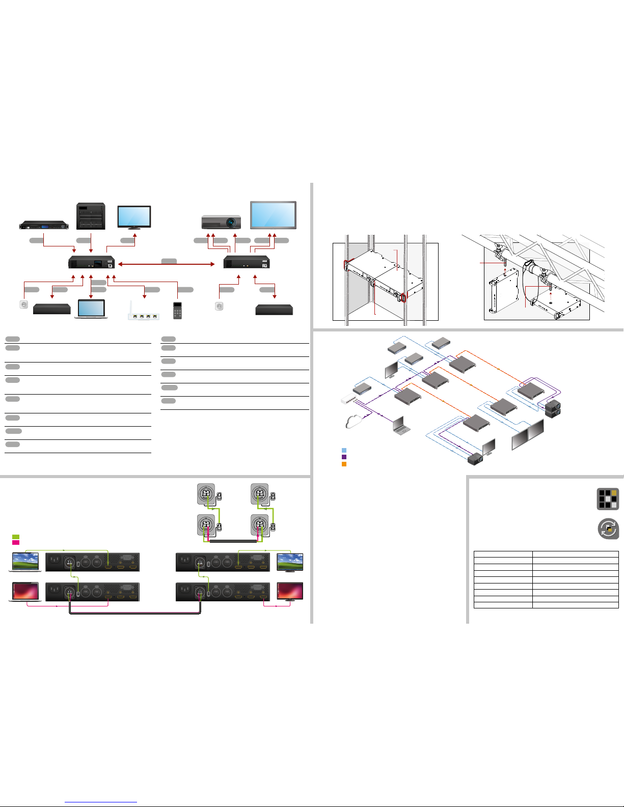
Neutrik OpticalCON connector has two ber channels. Lightware ber extenders use only one
ber for signal transmission and the other ber is available through the break-out connector.
In this case, one Neutrik OpticalCON Duo cable is enough to transmit two different A/V signal
from one transmitter pair to another receiver pair.
Software Control – Using Lightware Device Controller (LDC)
The device can be controlled from a computer using the Lightware Device
Controller software. The application is available at www.lightware.com, install
it on a Windows PC or a Mac OS X and connect to the device via LAN, USB
or RS-232.
Firmware Upgrade
Lightware Device Updater (LDU) is an easy and comfortable way to keep
your device up-to-date. Establish the connection via Ethernet. Download
and install LDU software from the company’s website www.lightware.com
where you can nd the latest rmware package as well.
Factory Default Settings
IP address - Transmitter (static) 192.168.0.101
IP address - Receiver (static) 192.168.0.102
Subnet mask 255.255.255.0
Static gateway 192.168.0.1
DHCP Disabled
TCP/IP port nr. LW3 6107
RS-232 port setting 57600 BAUD, 8, N, 1
Crosspoint setting input 1 on all outputs
Emulated EDID D1
Typical Application
Typical Application Description
The two Ethernet connectors on each extender make possible to daisy chain the devices
and build a local network where all the transmitters (1..3) and receivers (1..3) are available
via LAN.
They can be controlled by Lightware Device Controller (LDC) software from the laptop.
Optical ber cable transmits the HDMI, embedded audio, Ethernet, and RS-232 signal to the
receivers, so in this case, the sinks can be controlled by Ethernet commands from the control
device (laptop).
In this example, all the sources send HDMI 2.0 4K@60Hz 4:4:4 A/V signal to the transmitters
which extend the stream to the receivers via multimode ber cable.
Receiver 1..3 represent three applications of the output modes:
RX1 is in transparent mode (no conversion mode), the sinks are stacked projectors.
The video signal is HDMI 2.0 4K@60Hz 4:4:4 on the Output 1A and the Output 2 ports.
RX2 is in downsample convert mode (convert to YCbCr 4:2:0). The LED screen 2 is 4K
compatible and connected to the Output 2 port. LED screen 1 is not HDMI 2.0 4K@60Hz
4:4:4 compliant, so the video processor in the receiver converts the HDMI signal from
4:4:4 to 4:2:0, and this way the sink will be able to accept the signal on the Output 1B.
RX3 is in split mode. The receiver supports vertical splitting of the HDMI 2.0 4K@60Hz
4:4:4 input signal to left and right halves allowing for the transmission of an 18Gbps
HDMI 2.0 signal over two HDMI1.4 compliant links. The sink is a projector which is able
to recombine two half signal. Video signal is transmitted to the Output 2 without any
changing.
Connecting Steps
OPT
Connect a multimode (MM) fiber cable to the channel A of the transmitter.
OPT
Optionally connect a compatible Lightware device or a third-party device to the
break-out LC connector. It is internally linked to the channel B of the Neutrik
connector.
HDMI
Connect an HDMI source (e.g. video processor or media server) to any of the
inputs of the transmitter.
HDMI
Optionally connect an HDMI sink (e.g. confidence monitor) to the HDMI output
of the transmitter. The displayed signal of the output port is equal with the
extended video signal.
LAN
Optionally connect Ethernet devices (e.g. switch, laptop, computer etc.) to the
available Neutrik etherCON connector(s) of the extender(s). All connected
devices will work as if they are connected to the same network.
USB
Optionally connect a USB mini-B type cable between the transmitter unit and
the computer in order to control the device.
RS-232
Optionally for RS-232 extension: connect a controller unit (e.g. button panel) to
the RS-232 port of the transmitter with a null modem serial cable.
Power
Connect the power cord to the AC power socket to the transmitter unit. It is
recommended to power on the devices as the final step.
Connecting the transmitter and receiver to the same LAN beside they are connected to
each other via ber is not recommended. In case of Ethernet loop, the extenders are not
available via LAN.
OPT
Connect a multimode (MM) fiber cable to the channel B of the receiver.
OPT
Optionally connect a compatible Lightware device or a third-party device to the
break-out LC connector. It is internally linked to the channel A of Neutrik connector.
HDMI
Connect an HDMI sink (e.g. 4K projector) to the HDMI 1A and the 1B output ports
and an other sink (e.g. LCD screen) to the HDMI 2 output port.
LAN
In order to control, optionally connect Ethernet devices (e.g. 4K LCD screen) to
the available Neutrik etherCON connector of the extender.
RS-232
Optionally for RS-232 extension: connect a controlled device (e.g. Projector) to
RS-232 port of the receiver with a serial cable.
Power
Connect the power cord to AC power socket to the receiver unit. It is
recommended to power on the devices as the final step.
Always use high quality HDMI cable for connecting the sources with the transmitters, and
sinks with the receivers.
Mounting as a Standard Rack Installation (HDMI20-OPTC-TX220-Pro)
1. Two mounting holes on the front ears and two on the back of the chassis is for fastening
two units to each other with 2x 2pcs M4x8 mm screws. This way you get a one-rack
wide and 1U high device.
2. Fix the rack ears on left and right side as shown in the picture. The default position allows
mounting the device as a standard rack unit.
To order rack mounting kit please contact [email protected].
Truss Mounting (HDMI20-OPTC-RX220-Pro)
Mounting thread on top and on one of the sides is for safe and secure installation. Rigging
the handles with a safety wire rope is highly recommended for safety reasons. (Truss
mounting clamp and safety wire rope are not available at sales.)
Using different (e.g. longer) screws may cause damage to the device.
Pay attention to the ventilation holes when designing the system or the extender is
built into furniture. Side ventilation holes must not be covered.
HDMI
LAN
Optical fiber
TX
HDMI20
OPTC
POWER / LIVE
FIBER LINK
HDCP
INPUT1
INPUT2
SELECT
USB
CONTROL
HDMI20-OPTC-TX220-Pro
HDMI 2.0 Multimode Fiber Transmitter
TX
HDMI20
OPTC
POWER / LIVE
FIBER LINK
HDCP
INPUT1
INPUT2
SELECT
USB
CONTROL
HDMI20-OPTC-TX220-Pro
HDMI 2.0 Multimode Fiber Transmitter
TX
HDMI20
OPTC
POWER / LIVE
FIBER LINK
HDCP
INPUT1
INPUT2
SELECT
USB
CONTROL
HDMI20-OPTC-TX220-Pro
HDMI 2.0 Multimode Fiber Transmitter
RX
HDMI20
OPTC
POWER / LIVE
FIBER LINK
HDCP
INPUT1
INPUT2
SELECT
USB
CONTROL
HDMI20-OPTC-RX220-Pro
HDMI 2.0 Multimode Fiber Receiver
RX
HDMI20
OPTC
POWER / LIVE
FIBER LINK
HDCP
INPUT1
INPUT2
SELECT
USB
CONTROL
HDMI20-OPTC-RX220-Pro
HDMI 2.0 Multimode Fiber Receiver
RX
HDMI20
OPTC
POWER / LIVE
FIBER LINK
HDCP
INPUT1
INPUT2
SELECT
USB
CONTROL
HDMI20-OPTC-RX220-Pro
HDMI 2.0 Multimode Fiber Receiver
RX1
RX2
RX3
TX1
TX2
Media
player 1
Media
player 3
Media
player 2
Local
LCD
LCD
monitor
LED screen
1
LED screen
2
Media
player 4
Projector
3
Laptop
LDC Control TX 1-3
LDC Control RX 1-3
Control Projector 1-3
Up to 700 m
OUTPUT 1A (18G)
OUTPUT 2 (18G 4:4:4)
OUTPUT 1B (9G 4:2:0)
OUTPUT 2 (18G)
OUTPUT 1A (1×9G L/R)
OUTPUT 1B (1×9G L/R)
OUTPUT 2 (18G)
Up to 700 m
Up to 700 m
Projector
1
Projector
2
TX3
Media
player 2
INTERNET
Ethernet switch
HDMI20-OPTC-RX220-Pro
HDMI20-OPTC-TX220-Pro
OPT
Video processor
Media server
Confidence monitor
4K projector
LCD screen
Power
LW or third-party
fiber device
Laptop Ethernet switch Button panel
LW or third-party
fiber device
HDMI HDMI HDMI
Power
OPT
USB
LAN RS-232
LAN
HDMI HDMI
OPTPower
Power
LAN
HDMI RS-232
HDMI20-OPTC-RX220-Pro
HDMI 2.0 Multimode Fiber Receiver
POWER / LIVE
FIBER LINK
HDCP
SIGNAL PRESENT
OUTPUT CONVERSION
CONTROL
FUNCTION
USB
HDMI20
OPTC
220-PRO
MAIN MENU
> System Settings
Ports
EDID
Health
Remote
POWER / LIVE
FIBER LINK
HDCP
INPUT 1
INPUT 2
CONTROL
SELECT
USB
HDMI20
OPTC
220-PRO
HDMI20-OPTC-TX220-Pro
HDMI 2.0 Multimode Fiber Transmitter
B
A
A
B
A
A
B
A
B
B
A
B
B
B A
B
B A
A
B A
A
B A
HDMI20-OPTC-TX220-Pro
HDMI20-OPTC
-TX220-Pro
HDMI20-OPTC-RX220-Pro
HDMI20-OPTC-RX220-Pro
LC-LC fiber
optical cable
LC-LC fiber
optical cable
Neutrik opticalCON up to 700m
Source 1. Sink 1.
Sink 2.
Source 2.
A/V Video Signal 1.
A/V Video Signal 2.
HDMI
HDMI
HDMI
HDMI
2 pcs
M4x8mm
screws
2 pcs
M4x8mm
screws
M10x16mm
screw
M10x16mm
screw
 Loading...