

Page 1
Quick Start Guide
EDID MANAGER V4
Further information
The document is valid with the following rmware version: 1.2.3
The product brief and further information are available at www.lightware.eu.
See the Downloads section on the website of the product.
Contact us
+36 1 255 3800
+36 1 255 3810
Lightware Visual Engineering LLC.
Peterdy 15, Budapest H-1071, Hungary
Doc. ver.: 2.1
19200051
Power
Projector
Power adaptor
EDID
MANAGER
V4
PC
DVI DVI
USB
Laptop
Safety and
Warranty
Info
Quick
Start
Guide
3
6
8
5
9
w
1
4
7
2
e
q
DVI
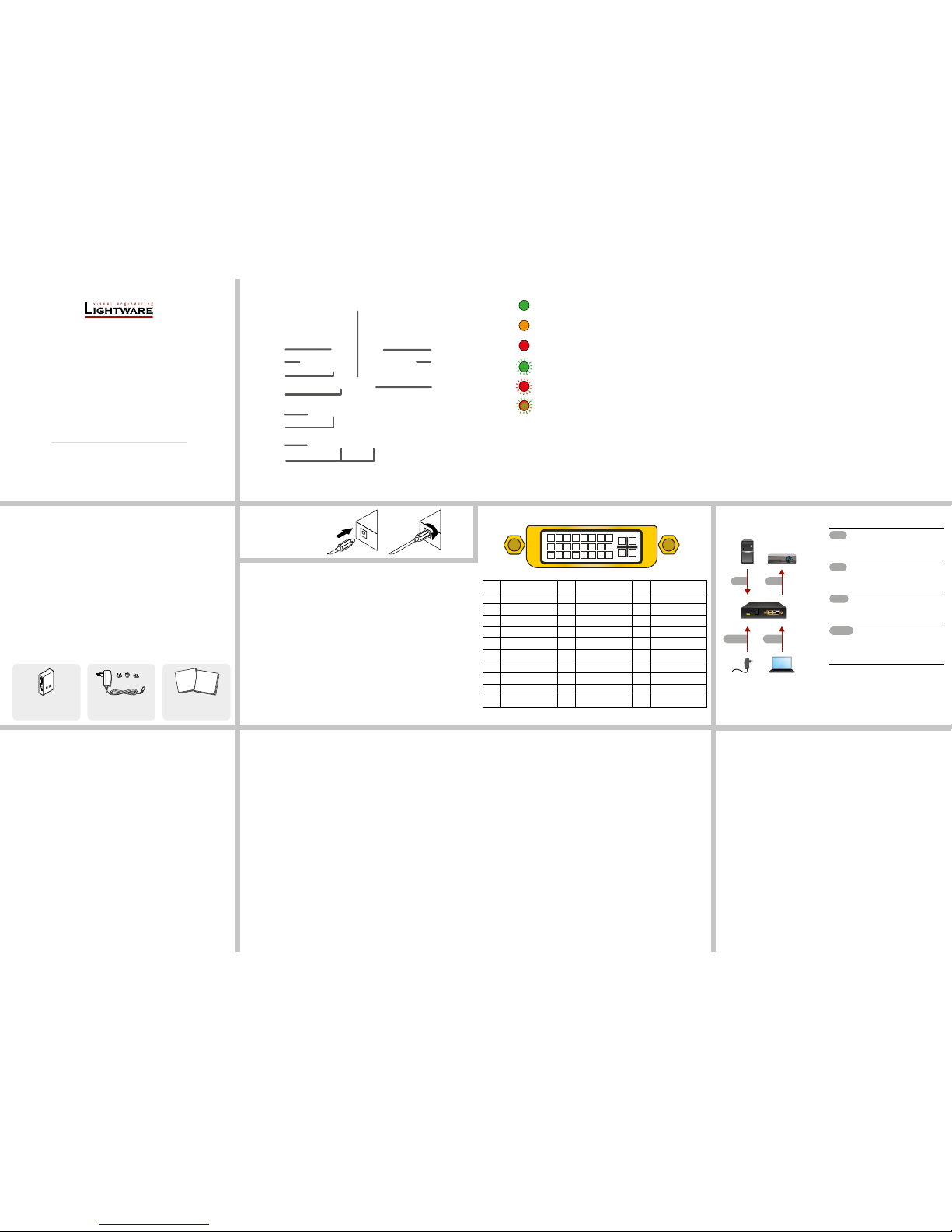
Connect the EDID Manager
V4 and the source device (e.g.
PC) using a DVI cable.
DVI
Connect the EDID Manager
V4 and the sink device (e.g.
projector) using a DVI cable.
USB
Optionally connect a controller
device (e.g. laptop) to the USB
port of the device.
Power
Firstly connect the power
adaptor to the DC input on the
device, then to the AC power
socket.
Powering on the devices is recommended to
do as the nal step during the installation.
Important safety instructions
Please read and keep the information in the attached safety instructions supplied with the
product before you start using the device.
Introduction
Thank You for choosing Lightware EDID MANAGER V4, our HDCP compatible HDMI/DVI
EDID Emulator and cable extender with USB control. The device can store 79 EDIDs. It
emulates and keeps a xed EDID for the source. Thanks to our Advanced EDID Management,
the device can trick the source (PC computer, laptop, etc.) by emulating any DVI/HDMI display
(LCD monitor, projector) for continuous video output - even if the AV system is disconnected or
powered down. With EDID emulation, the user can set up any DVI or HDMI output resolution,
regardless of the used projector or monitor. This ensures that the overall system resolution can
be controlled. There are 49 factory and 29 user programmable presets available, and the last
attached display device’s EDID is also stored separately on address 00#, to be able to clone
it to the input (clone mode).
Box Contents
EDID MANAGER V4 unit 5V DC adaptor with
interchangeable plugs
Safety and warranty info,
Quick Start Guide
Connecting Steps
Top View
1
Status LED LED gives feedback about the current status of the device.
ON - GREEN: EDID and HDCP status indicator: if the selected
EDID is valid and HDCP is enabled the LED lights green.
ON - ORANGE: EDID and HDCP status indicator: if the selected
EDID is valid and HDCP is disabled the LED lights orange.
ON - RED: EDID status indicator: if the selected EDID is invalid
the LED lights red.
BLINKING - GREEN: EDID status indicator: Burn / Learn
process or reading connected device’s EDID was successful.
BLINKING - RED: EDID status indicatior: Burn / Learn process
or reading connected device’s EDID failed.
BLINKING - RED/GREEN: Firmware upgrade status indicator:
during rmware upgrade the LED ashes red and green.
2
Signal
Present LED
Indicates if a valid DVI / HDMI clock signal is present on the DVI
IN connector.
3
DVI IN
connector
DVI-I input connector for DVI-D / HDMI signal.
4
Source +5V
LED
Indicates if 5V power signal is sent to pin 14 of the input DVI
connector by the DVI source (PC, Laptop, etc.).
Locking DC Plug
Twist 90° clockwise to lock.
5
Burn button Reprograms the attached device’s input EDID data (legacy
purpose). Attention: burning a wrong EDID can damage the display!
6
DC input
connector
Locking 5V DC power input connector, center pin positive.
Protected from polarity exchange.
7
Power LED The LED indicates the presence of proper power supply voltage.
8
USB
connector
USB interface for LDC connection (Advanced EDID
management) and firmware upgrade.
9
EDID Rotary
switches
The rotary switches select one of the EDID memory addresses.
Addresses 01#..49# are factory presets and 51#..79# are user
programmable presets. Address 00# enables transparent mode.
Address 01# is also used for HDCP status change.
q
Learn button Stores the EDID of the display device attached to DVI OUT in
the selected memory address between 51#..79#. To learn the
EDID, select an appropriate address with the rotary switches
and press and hold the Learn button for two seconds.
w
DVI OUT
connector
DVI-I output connector for DVI-D / HDMI signal.
e
Monitor
Hotplug LED
Indicates if a powered display device (or matrix switcher,
repeater, etc.) is connected to the DVI output connector and
sends a valid hotplug signal on pin 16 through the DVI cable.
Pinout of the DVI-I Connector
Pin Signal Pin Signal Pin Signal
1 TMDS Data2- 9 TMDS Data1- 17 TMDS Data0-
2 TMDS Data2+ 10 TMDS Data1+ 18 TMDS Data0+
3 TMDS Data2 Shield 11 TMDS Data1 Shield 19 TMDS Data0 Shield
4 Not connected 12 Not connected 20 Not connected
5 Not connected 13 Not connected 21 Not connected
6 DDC Clock 14 +5V Power 22 TMDS Clock Shield
7 DDC Data 15 GND (for +5V) 23 TMDS Clock+
8 Not connected 16 Hot Plug Detect 24 TMDS Clock-
C1 Not connected C2 Not connected C3 Not connected
C4 Not connected C5 GND
1
2 3
4
5 6 7 8
16
24
9 1011121314
15
17
18 19 202122 23
C1 C2
C3
C4
C5
DVI Connectors
DVI Input
The input has a built-in signal detection circuit with a LED indicator. The Signal Present LED
lights green, if the INPUT connector senses an active DVI/HDMI signal.
DVI Output
Monitor hotplug is detected on the output port (Monitor Hotplug LED lights green). After a
hotplug event, the EDID Manager V4 tries to read the EDID of the connected device. No output
reclocking is provided. If a long DVI cable is connected then equalization and reclocking may
be necessary at the receiver end of the cable.
Fiber Cable Powering
As a special feature, the device is able to supply 500 mA current on DDC +5V output (pin 14 on
output connector) to power ber optical DVI transmitters. Standard DVI outputs or VGA cards
supply only 55 mA current on +5V output, thus unable to power directly a ber optical cable.
Appliable Cable Length
Maximum 60 meters 22AWG DVI cable is recommended for 1080p (Full HD) resolution on
the input.
Features
Advanced EDID Management – The user can emulate any EDID on the device’s input
by using the 49 factory or 29 user presets. Any attached monitor’s EDID can be read out,
edited and stored as user presets by the Lightware Device Controller Software.
HDCP Management – HDCP communication between source and display devices can
be permitted or prohibited by the unit. Lightware is a legal HDCP adopter.
60 meter input cable compensation – Using 22AWG high quality DVI cable, the input
is automatically compensated for up to 60 meter cable length, which extends installation
possibilities even on highest HDTV or computer resolutions. In case of lower pixel
resolutions, this length can be even higher.
Top panel control – EDID address selection with two decimal rotary switches, Learn
EDID and Burn EDID buttons are available for Advanced EDID Management.
USB control – The EDID Manager V4 is controllable via the Lightware Device Controller
software where Advanced EDID Management is available. Firmware upgrade can also
be performed over this interface.
Supports all HDTV resolutions – Supports HDCP encrypted and unencrypted HDTV
signals up to 225 MHz pixel clock frequency regardless of the resolution being passed
through. (720p, 1080i and 1080p etc.)
Fiber cable support – Self-powered DVI ber cables using +5V from DVI sources
(VGA cards, etc.) usually consumes more than 50 mA (maximum suggested by DVI 1.0
standard). Lightware devices support +5V 500 mA constant current output on the DVI
outputs to power long distance ber optical cables.
Specication
General
Compliance ...............................................................................................................CE
EMI / EMC ..................................................................................EN 55024 / EN 55032
Safety ..................................................................................................................Class II
Warranty .............................................................................................................3 years
Cooling .............................................................................................................. passive
Power consumption ....................................................................................... 2 W (max)
Operating temperature .......................................................0 to +50˚C (+32 to +122˚F)
Operating humidity .........................................................10% to 90%, non-condensing
Enclosure
DC power connector ..............................................locking DC connector, 2.5 / 5.5 mm
Material .........................................................................................................1 mm steel
Dimensions ..................100.4 W x 67.6 D x 26 H mm (3.95 W x 2.66 D x 1.02 H inch)
Weight .................................................................................................225 g (0.496 lbs)
Rack mountable .........................................................................................................No
Supplied Power Adaptor
Input .............................................................................AC 100-240 V, 50~60 Hz, 0.6 A
Output ........................................................................................................DC 5V, 2.6 A
Input
Connector ...............................................................................29-pole DVI-I digital only
Input cable equalization ...................................................................... Yes, +40 dB max
EDID emulation.........................................................................................................Ye s
HDCP compliant .......................................................................................................Yes
Output
Connector ...............................................................................29 pole DVI-I digital only
Reclocking .................................................................................................................No
+5V output current ..............................................................................................500 mA
Signal
Data rate .................................all between 250 Mbps and 2.25 Gbps / TMDS channel
Channels .................................................................1x TMDS Clock + 3x TMDS Colors
Resolutions ............................................all between 640x480 and 1920x1200@60Hz,
.....................................................................................................or 2048x1080@60Hz
Color depth .....................................................................maximum 36 bits, 12 bit/color
Color space ................................................................................................RGB, YCbCr
HDTV resolutions ............................................................................720p, 1080i, 1080p
HDMI 1.3a compatible ........................................................Yes (with embedded audio)
HDCP compliant .......................................................................................................Yes
Page 2
MEM01 + Learn =
HDCP enable/disable
PC
Monitor
Projector
A/V system
Projector
EDID Manager V4
DVI cable
(max. 60 m)
DVI
DVI
DVI
MEM01 + Learn =
HDCP enable/disable
EDID Manager V4 HDCP-capable
A/V system
HDCP-compatible
Projector
Non-HDCP
Projector
Non-HDCP
Monitor
Laptop
HDCP is enabled
between the source
and the display
GREEN:
RED:
ORANGE:
VALID
INVALID
VALID
DISABLED
EDID
ENABLED
HDCP
N/A
COMPUTER
( )
DVI IN
POWER
SIGNAL
PRESENT
BURN
LEARN
MONITOR
HOTPLUG
x10
x1
SOURCE +5V
STATUS
DC IN
EDID MEMORY
MEM00: Copy from DVI OUT
HDCP enable/disable
MEM01 + LEARN =
DVI OUT
( )
MONITOR
USB
EDID MANAGER V4
Resolution Resolution
MEM MEM
1364x768@60
1364x768@75
1280x1024@50
1366x1024@60
1400x1050@50
1400x1050@60
1400x1050@75
640x480@60
640x480@75
848x480@60
800x600@50
800x600@60
800x600@75
1024x768@50
1024x768@60
1024x768@75
1152x864@75
1280x768@50
1280x768@60
1280x768@75
1360x768@60
1364x768@50
1280x1024@60
1280x1024@75 1920x1080p@60
2048x1080p 1@50
2048x1080p@60
1600x1200@60
1600x1200@50
1920x1200@60
1920x1200@50
720x576p@50
1280x720p@50
1280x720p@60
26
27
28
29
30
31
32
33
34
35
36
37
38
39
40
41
42
43
44
45
46
47
48
16
17
18
19
20
21
22
23
24
25
01
02
03
04
05
06
07
08
09
10
11
12
13
14
15
1920x1080i 1@50
1920x1080i 2@50
1920x1080i@60
1920x1080p@24
1920x1080p@25
1920x1080p@30
1920x1080p 1@50
1920x1080p 2@50
2048x1080p 2@50
576i@50
1680x1050@60
UNIVERSAL EDID
Made in EU, Hungary
RoHS
49
Sn:
Copy from DVI out
00
5V DC 1A
67.626
100.4
Right View Top View
Bottom View
Left View Side View
26
X
MEM01 + Learn =
HDCP enable/disable
Non-HDCP
Projector
A/V system
HDCP-compatible
Projector
EDID Manager V4
HDCP is disabled
between the source
and the display
Laptop
Non-HDCP
Monitor
Software Control – Using Lightware Device Controller (LDC)
The device can be controlled from a computer through the USB port
using Lightware Device Controller. Please download the application from
www.lightware.eu, install on a Windows PC or a Mac OS X and connect to
the device via the USB port.
I/O Parameters Menu
Input port: information about port status can be checked and HDCP can be enabled/
disabled.
Output port: information about port status can be checked.
EDID Menu
Advanced EDID Management can be accessed by selecting the EDID menu. There are two
panels: left one contains Source EDIDs, right one contains Destination places where the
EDIDs can be copied.
EDID Editor
Select an EDID from Source panel and press Edit button to display
Advanced EDID Editor window. The editor can read and write all
descriptors, which are dened in the standards, including the additional
CEA extensions. Any EDID from the device’s memory or a saved EDID le can be loaded into
the editor. The software resolves the raw EDID and displays it as readable information to the
user. All descriptors can be edited, and saved in an EDID le, or uploaded to the User memory.
For more details about EDID Editor please visit our website (www.lightware.eu) and download
EDID Editor user’s manual.
A
Edit
HDCP Operations
Enable HDCP
1. Turn the rotary switches to memory address #01.
Avoid the use of keys, coins, knives and other sharp objects.
2. Check the status of the device (STATUS LED):
GREEN: valid EDID data is present at input, HDCP pass-through enabled.
ORANGE: valid EDID data is present at input, HDCP pass-through disabled.
3. Press and hold the LEARN button for approximately 3 seconds to change HDCP status.
4. The STATUS LED changes color according to the new HDCP pass-through state.
5. To emulate an EDID turn the rotary switches to the desired position.
HDCP Management
HDCP capable and non-capable sink devices in the same system can lead to improper setup;
there can be monitors/projectors, which will not display the signal from the source. To force
the signal sources to output non-encrypted signal, HDCP pass-through can be disabled in
the EDID Manager V4. If the content is not copyrighted the source will output proper, nonencrypted signal.
0
1
2
3
4
5
6
7
8
9
0
1
2
3
4
5
6
7
8
9
EDID Operations
Selecting an EDID
1. Turn the rotary switches to the desired memory address. Use a
at head screwdriver to change the address. The left switch sets
the tens value, the right switch gives the ones value of the EDID.
Avoid the use of keys, coins, knives and other sharp objects.
2. The Status LED will turn red/green/orange:
RED: an empty memory or invalid EDID data was selected.
GREEN: valid EDID data is present at input, HDCP is enabled.
ORANGE: valid EDID data is present at input, HDCP is disabled.
3. Now the selected EDID is emulated at DVI INPUT.
Learning an EDID
1. Turn the rotary switches to the desired memory address where you want to store the
attached display’s EDID (between user addresses #51..#79).
2. Connect the display device to the EDID Manager’s DVI OUT.
3. If the Status LED blinks in red, EDID is cannot be read from the display device and the
learning procedure will be unsuccessful. In this case the last successfully read EDID is
written in the desired user memory address.
4. Press and hold the LEARN button for approximately 3 seconds.
5. The STATUS LED will ash red or green:
GREEN: the learn process was successful,
RED: the learn process failed.
0
1
2
3
4
5
6
7
8
9
0
1
2
3
4
5
6
7
8
9
EDID Management
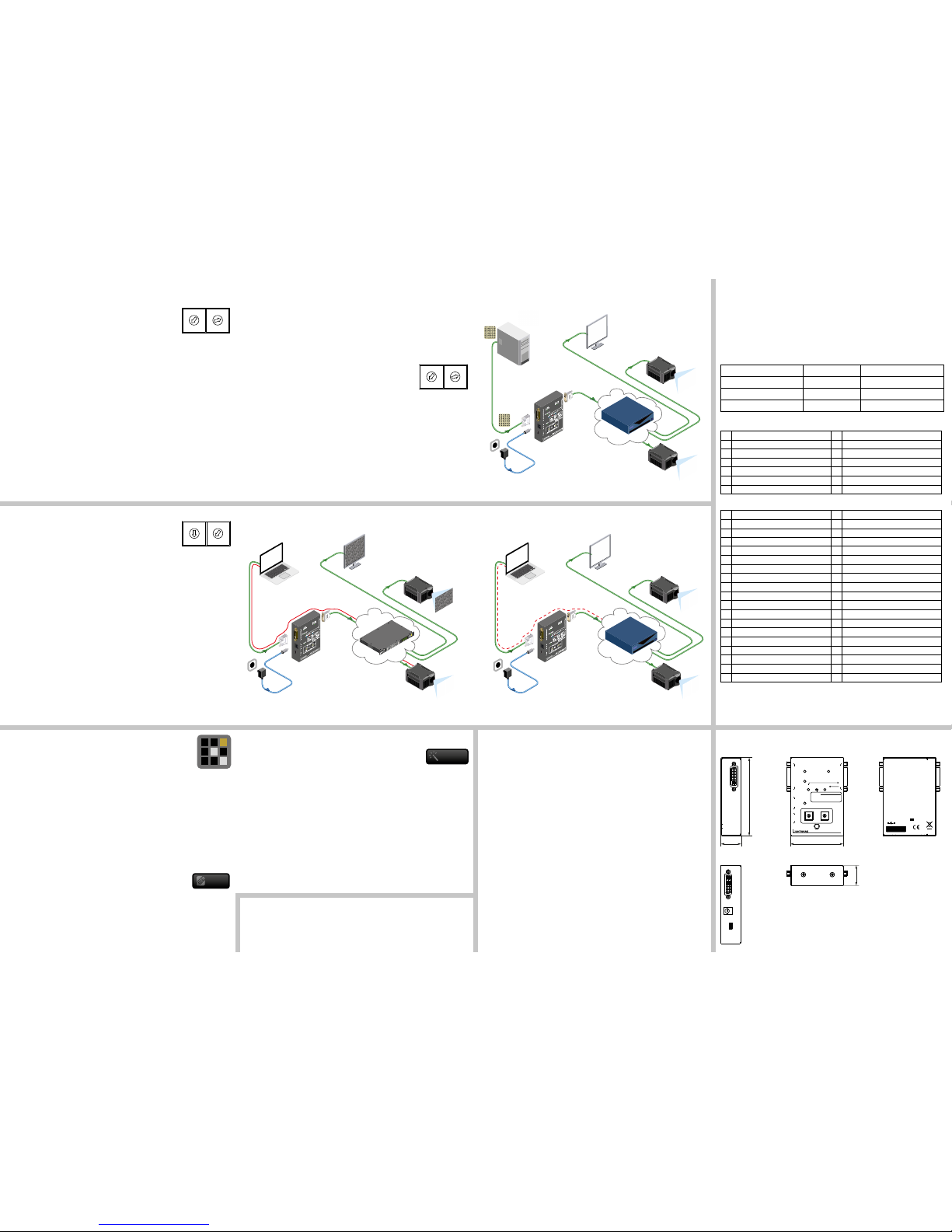
Enabled HDCP - Example Disabled HDCP - Example
EDID Memory Structure
Lightware factory preloaded EDIDs (except the Universal EDID) are specially provided to force
the sources to output only the exact pixel resolution and refresh rate.
Universal EDID (address 49#) allows multiple resolutions including all common VESA
dened resolutions. In addition, it also features audio support. The use of a universal EDID is
advised for fast and easy system setup.
EDID manager V4 contains a 79 block non-volatile memory bank. EDID memory is structured
as follows:
Description Rotary switch state Memory bank number in LDC
Factory Preset EDID list 01# - 49# F01# - F49#
User programmable slots 51# - 79# U1# - U29#
Last attached monitor’s EDID 00# D01
Factory Preset EDID List
ID Resolution ID Resolution
01 640 x 480 @ 60.00 Hz 26 1600 x 1200 @ 50.00 Hz
02 640 x 480 @ 75.00 Hz 27 1600 x 1200 @ 60.00 Hz
03 848 x 480 @ 50.00 Hz 28 1920 x 1200 @ 59.55 Hz
04 800 x 600 @ 50.00 Hz 29 1920 x 1200 @ 50.00 Hz
05 800 x 600 @ 60.30 Hz 30 1440 x 240 @ 60.30 Hz
06 800 x 600 @ 74.99 Hz 31 640 x 480 @ 59.94 Hz
07 1024 x 768 @ 49.98 Hz 32 720 x 480 @ 59.92 Hz
08 1024 x 768 @ 60.00 Hz 33 1440 x 288 @ 50.60 Hz
09 1024 x 768 @ 75.20 Hz 34 720 x 576 @ 50.00 Hz
10 1152 x 864 @ 75.00 Hz 35 1280 x 720 @ 50.00 Hz
11 1280 x 768 @ 50.00 Hz 36 1280 x 720 @ 60.00 Hz
12 1280 x 768 @ 59.92 Hz 37 1920 x 540 @ 50.30 Hz
13 1280 x 768 @ 75.00 Hz 38 1920 x 540 @ 50.00 Hz
14 1360 x 768 @ 60.10 Hz 39 1920 x 540 @ 60.50 Hz
15 1364 x 768 @ 50.00 Hz 40 1920 x 1080 @ 24.00 Hz
16 1364 x 768 @ 59.93 Hz 41 1920 x 1080 @ 24.99 Hz
17 1364 x 768 @ 74.98 Hz 42 1920 x 1080 @ 30.00 Hz
18 1280 x 1024 @ 50.00 Hz 43 1920 x 1080 @ 50.00 Hz
19 1280 x 1024 @ 60.10 Hz 44 1920 x 1080 @ 49.99 Hz
20 1280 x 1024 @ 75.10 Hz 45 1920 x 1080 @ 60.00 Hz
21 1366 x 1024 @ 59.99 Hz 46 2048 x 1080 @ 49.99 Hz
22 1400 x 1050 @ 49.99 Hz 47 2048 x 1080 @ 50.00 Hz
23 1400 x 1050 @ 59.99 Hz 48 2048 x 1080 @ 59.99 Hz
24 1400 x 1050 @ 75.00 Hz 49 1920 x 1080 @ 60.00 Hz
25 1680 x 1050 @ 59.99 Hz 50 Reserved
The Factory Preset EDID list cannot be modied. These are the most commonly used
resolutions.
Firmware Upgrade
The Lightware Bootloader software can be used to upgrade your device. Install the software
to your computer and get the latest rmware from Lightware Support ([email protected]).
Please check the details about upgrade procedure in the user’s manual of the LW Bootloader
software.
Mechanical DrawingsTroubleshooting
General Problems
Check the device - Check whether the EDID Manager V4 is properly powered and the Power
LED is green. Try performing a reset by unplugging and reconnecting the power adaptor.
Picture is not Displayed or Distorted
Check the cables - DVI connectors have to be locked with screws, no tensions or breaches
are allowed. If your source or display has more connectors then make sure that the proper
interface is selected. Although the device is equipped with DVI-I connectors, analog signals
are not supported. You cannot use VGA cables with DVI-VGA adapter plugs.
Check EDID related problems - Maybe your display device is not capable of receiving
the sent video format. Try emulating your display device’s EDID to the source by selecting
00# on the front panel Rotary switch.
Check the source - Check whether your source is powered on and congured properly.
The HDMI output can be turned off on most DVD players. If the source is a computer, then
verify that the OUTPUT is selected and active. Try restarting your computer; if you get a
picture during the booting process, you have to review the driver settings.
HDCP Issues
Non HDCP compliant display - Some video sources send HDCP protected signal if
they detect that the sink is HDCP capable – even if the content is not copyrighted. This
can cause trouble if a HDCP capable device (e.g. HDMI matrix) is connected between
the source and the display. In this case the content can’t be viewed on non-DCP capable
displays. Disable HDCP on the device by switching the rotary switches to address 01#
and holding the Learn button.
Creating an EDID - Easy EDID Creator
Since Advanced EDID Editor needs more complex knowledge about
EDID, Lightware introduced a wizard-like interface for fast and easy EDID
creation. With Easy EDID Creator it is possible to create custom EDIDs
in four simple steps. By clicking on the Create button below Source panel, Easy EDID Creator
is opened in a new window. For more details about EDID Creator please visit our website
(www.lightware.eu) and download EDID Editor user’s manual.
Settings Menu
Device Information: the most important information (serial number, rmware and
hardware versions, etc.) about the device.
Log: LDC is able to collect information from the device and save it to a report le. This
information package can be sent to Lightware Support when a problem may arise with
the device.
A
Create
Burning the EDID
Sink devices store their EDID information in a non-volatile memory (EEPROM). Normally this
memory is write-protected in monitors and projectors, thus it cannot be modied by the Burn
EDID function of the EDID Manager V4. Some of them however are not write protected, so
users must be very careful when using this function.
Burning a wrong EDID can damage the display!
Users can burn EDID in the inputs of any DVI Matrix Switcher that doesn’t have built-in EDID
management function as long as its EEPROMs are not write protected.
1. After connecting the sink device to DVI OUT of the unit, use a
screwdriver to select the memory address of the EDID to be
burnt. If the Status LED lights green or orange, the memory slot
contains a valid EDID and it is ready to be burnt.
Avoid the use of keys, coins, knives and other sharp objects.
2. Push the BURN button and hold it down for approximately 10 seconds. Once the button
is pushed the Status LED goes dark. After the 10 seconds, the Status LED becomes
orange. Once the LED becomes orange, push and release the Burn button 3 times within
5 seconds. Now the burn process starts. If the Status LED blinks green, then the burn
process was successful. If it blinks red, then the burn process failed.
Factory Preset EDID list
The EDID list is on the back side of the device. The #30..#45 memory range contains EDIDs
supporting various embedded audio formats for HDMI audio and also #49 which is the
Universal EDID with HDMI.
0
1
2
3
4
5
6
7
8
9
0
1
2
3
4
5
6
7
8
9
 Loading...