

Lightware DVI-HDCP-TPS-TX210, DVI-HDCP-TPS-TX220, DP-TPS-TX220, HDMI-TPS-TX220, HDMI-TPS-TX210 Quick Start Manual
...Page 1
Quick Start Guide
DVI-HDCP-TPS-TX210, DVI-HDCP-TPS-TX220
HDMI-TPS-TX210, HDMI-TPS-TX220
DP-TPS-TX210, DP-TPS-TX220
Further information
The document is valid with the following rmware version: 1.1.4
The User’s manual of this appliance is available at www.lightware.com.
See the Downloads section on the dedicated product page.
Contact us
+36 1 255 3800
+36 1 255 3810
Lightware Visual Engineering LLC.
Peterdy 15, Budapest H-1071, Hungary
Doc. ver.: 2.1
19200111
Important Safety Instructions
Please read the supplied safety instruction document before using the product and keep it
available for future reference.
Introduction
Thank you for choosing Lightware TPS-TX200 series transmitter. The products have
HDBaseT
TM
integration with additional Lightware developments. The devices transmit HDMI/
DVI digital video signal up to 4K resolution, audio and control up to 170 m distance over a
single CAT cable (in case of DP-TPS transmitters the DP signal is converted to HDMI).
Compatible Devices
The transmitters are compatible with all Lightware
TPS receivers, matrix boards and third party
devices based on HDBase-T
TM
technology.
Power Supply Options
The transmitters can be powered:
Locally with the supplied 12V DC adaptor or Lightware’s rack mountable PSU, or
Remotely by a PoE-compatible power injector, like Lightware’s TPS-PI-1P1.
For more information please turn the paper.
TPS-TX/RX95 are not PoE-compatible, thus not able to remote power the TPS-TX200
series and vica versa. TPS-TX200 series contains PoE-compatible remote power function,
RX95 can be remote powered only by TX95 transmitter.
HDBaseTTM and the HDBaseT Alliance logo are trademarks of the HDBaseT Alliance.
Box Contents Connecting Steps
* Only for DVI-HDCP-TPS-TX220, HDMI-TPS-TX220 and DP-TPS-TX220 models.
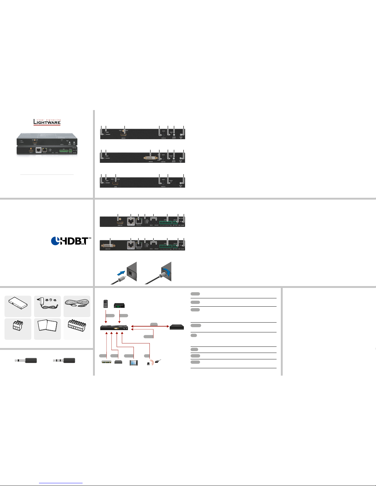
Front Views
Rear Views
Front Panel LEDs
Video Source
OFF: video source is not selected.
BLINKING: video source is selected but not active.
ON: video source is selected and active.
Audio Sources
OFF: audio source is not selected.
BLINKING: audio source is selected but not active.
ON: (with short pause): audio source is selected and the port is active but not embedded
to the output video stream (DVI output mode).
ON: (continuously): audio source is selected, the port is active and the audio is embedded
to the output video stream (HDMI output mode).
When Autoselect is enabled and audio signal is not present at all, audio LEDs blink.
HDCP LED
OFF: video output signal is not encrypted with HDCP.
ON: video output signal is encrypted with HDCP.
Autoselect LED
OFF: autoselect is disabled.
BLINKING: autoselect is enabled; searching for signal (audio LEDs also blink).
ON: autoselect is enabled; active signal is found (the LED of selected audio also lights).
Rear Panel LEDs
LIVE
OFF: device is not powered.
BLINKING (slow): device is powered and operational.
BLINKING (fast): device is in bootload mode.
ON: device is powered but no operation.
RS-232 LED
OFF: RS-232 ports (local and link) are in Pass-through mode.
BLINKING: command injection mode is active.
ON: RS-232 ports (local and link) are in Control mode.
SRVC
Reserved for future developments.
LINK
OFF: no TPS link between transmitter and receiver.
BLINKING (slow): low power mode is active.
BLINKING (fast): Ethernet fallback mode is active.
ON: TPS link is established, HDBaseT or Long Reach mode is active.
1
Autoselect LED LED gives feedback about the current Autoselect status.
2
HDCP LED LED gives feedback about the HDCP status of the output
signal.
3
DisplayPort input DisplayPort connector for DisplayPort audio/video signal.
4
HDMI input HDMI connector for DVI video or HDMI video and audio.
5
DVI-D input DVI-I connector for DVI-D video and audio.
6
Audio input 3.5 mm Jack connector for unbalanced analog audio
input signal.
7
Video select
button
Button for selecting a video source.
8
Audio select
button
Button for selecting an audio source.
9
Show me button Special functions can be reached using this button
(rmware upgrade (bootload) mode, DHCP settings,
restore factory default settings, condition launching in
Event Manager).
1
DVI-D output Local DVI-D output with the same A/V content as the
TPS output.
2
HDMI output Local HDMI output with the same A/V content as the TPS
output.
3
TPS output Locking RJ45 connector for HDBaseTTM signal
transmission.
4
Ethernet Locking RJ-45 connector for conguring the device using
Lightware Device Controller (LDC), or upgrading it using
Lightware Device Updater (LDU). Any third-party control
system can use this port to control the device.
5
Status LEDs The LEDs give feedback about the actual state of the
device.
6
IR IN and IR OUT 3-pole TRS connector, also known as 3.5 mm (1/8”) jack
plug for optional IR receiver (IR IN) and transmitter (IR
OUT) connection.
7
GPIO port 8-pole Phoenix connector for congurable general
purpose input/output ports.
8
RS-232 port 3-pole Phoenix connector for controlling the device by
LDC or third-party control systems.
9
12V DC input 12V DC input for local powering.
Transmitter unit 12V DC power adaptor
with interchangeable plugs
Infrared transmitter unit
Phoenix combicon
3-pole connector
Phoenix combicon
8-pole connector*
Safety and warranty info,
Quick Start Guide
Safety and
Warranty
Info
Quick
Start
Guide
Locking DC Plug
Twist 90° clockwise to lock.
DVI
Connect the source (e.g. a PC) to the DVI-I input port by a DVI cable.
Audio
Connect an audio source (e.g. a Media player) to the 3.5 analog audio input
port.
CATx
DVI
Connect the TPS output port of the transmitter to the TPS+PoE port of the
TPS-PI-1P1 by a CATx cable.
Connect the receiver (or the Matrix input board) to the power injector by a
CATx cable via the TPS port.
RS-232
Optionally for RS-232 extension: connect a controller/controlled device
(e.g. Touch panel) to the RS-232 port.
IR
Optionally for Infrared extension:
Connect the IR emitter to the IR OUT port of the transmitter, and/or
Connect the IR detector to the IR IN port of the transmitter.
LAN
Optionally connect the transmitter to a LAN.
GPIO
Optionally connect the transmitter to a LAN.
Power
Powering on the devices is recommended to do as the nal step during the
installation. Please see the Power Supply Options section for the details.
2 pole, 1 ring: IR transmitter 3 pole, 2 rings: IR receiver
Types of IR connectors (1/8” TRS / TS)
RS-232
AudioDVI-I
GPIO
Media player
IR
Ethernet
Infrared
Relay box
LAN
Touch panel
PC
DVI-HDCP-TPS-TX220
Autoselect
HDCP
DVI-D IN
AUDIO IN
SHOW
ME
AUDIO
SELECT
RESET
VIDEO
AUDIO
AUDIO
Power
Compatible
TPS Receiver
CATx
2 31 6 7
9
2 5 81 6 7
9
2 4 81 6 7
9
HDMI-TPS-TX220
DVI-HDCP-TPS-TX220
DP-TPS-TX220
2 3 4 5 76
9
8
1 3 4 5 76
9
8
HDMI-TPS-TX220, DP-TPS-TX220
DVI-HDCP-TPS-TX220
Page 2
Restore Factory Default Settings
1. Keep the Show me button pressed for 10 seconds; after 5 seconds front panel LEDs
start to blink but keep the buttons pressed; the LEDs start to blink faster 5 seconds later.
2. Release the button, then press it 3 times quickly; factory default settings are restored:
IP address (fix) 192.168.0.100
Subnet mask 255.255.255.0
Static gateway 192.168.0.1
DHCP Disabled
TCP/IP port nr. LW2 / LW3 10001 / 6107
Crosspoint setting (Audio) Embedded audio
Autoselect Disabled
Output TPS mode Auto
Emulated EDID Dynamic
RS-232 mode Pass-through
RS-232 control protocol LW2
RS-232 port setting 57600 BAUD, 8, N, 1
Command injection port (local / link) 8001 / 8002
GPIO output level / direction High / Input
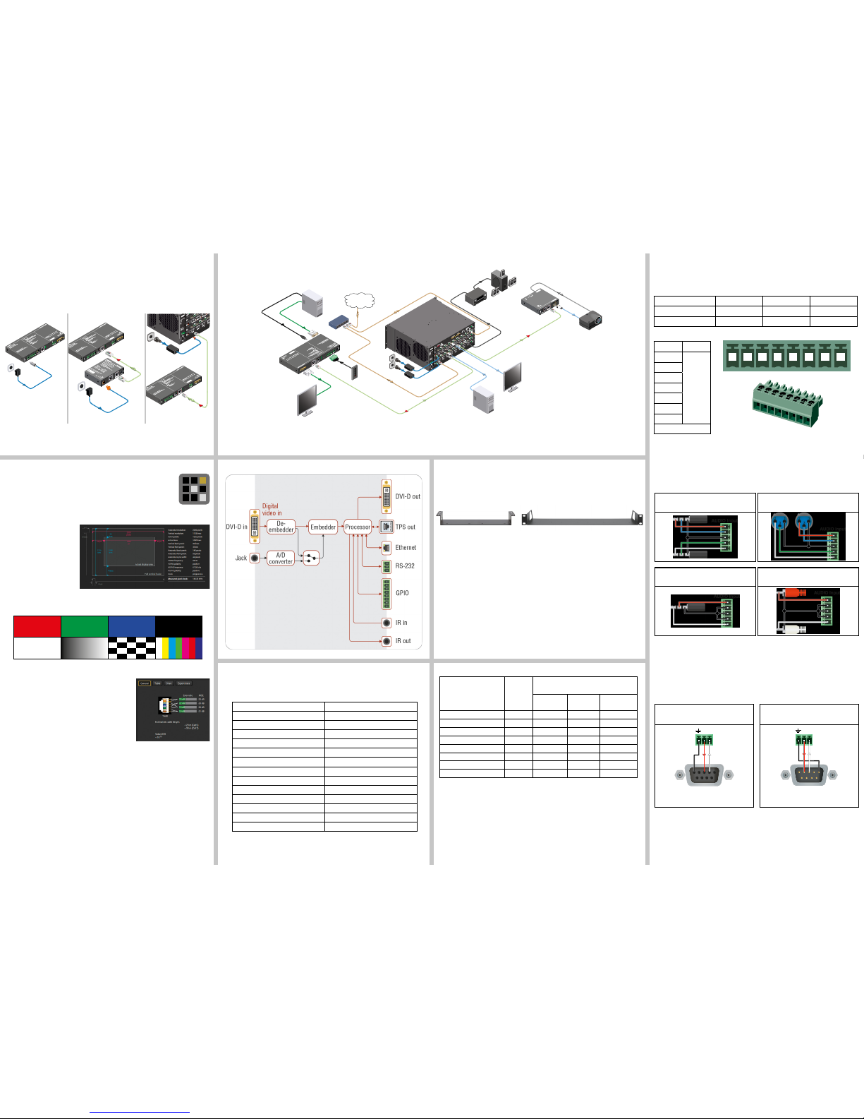
Maximum Extension Distances
Typical Application
Port Diagram (DVI-HDCP-TPS-TX220)
Resolution
Pixel
clock rate
Cable lengths
(Auto / Long reach TPS mode)
CA
T5e
AWG24
CA
T7
AWG26
CAT7
AWG23
1024x768@60Hz 65 MHz 100 m / 130 m* 90 m / 120 m* 120 m / 170 m*
1280x720p@60Hz 73.8 MHz 100 m / 130 m* 90 m / 120 m* 120 m / 170 m*
1920x1080p@60Hz (24bpp) 148.5 MHz 100 m / 130 m* 90 m / 120 m* 120 m / 170 m*
1920x1200@60Hz 152.9 MHz 100 m / NA 90 m / NA 120 m / NA
1600x1200@60Hz 162 MHz 100 m / NA 90 m / NA 120 m / NA
1920x1080@60Hz (36bpp) 223 MHz 70 m / NA 70 m / NA 100 m / NA
3840x2160@30Hz UHD 297 MHz 70 m / NA 70 m / NA 100 m / NA
4096x2160@30Hz 4K 297 MHz 70 m / NA 70 m / NA 100 m / NA
* Long reach TPS mode supports pixel clock frequencies up to 148.5 MHz.
Above values are valid when the transmitter is powered by a local adaptor; distances may
decrease depending on the powering mode (local or remote) and cable quality. To specify
the accurate extension distances, please also check the documentation of the connected
HDBaseT-compatible device.
CAT7 SFTP AWG23 cable is always recommended.
Wiring Guide for RS-232 Data Transmission
The transmitters are built with 3-pole Phoenix connector. See the below examples of connecting
to a DCE (Data Circuit-terminating Equipment) or a DTE (Data Terminal Equipment) type
device:
For more information about the cable wiring see the user’s manual of the device or the Cable
Wiring Guide on our website www.lightware.com/support/guides-and-white-papers.
Software Control – Using Lightware Device Controller (LDC)
The device can be controlled from a computer through the Ethernet port
using Lightware Device Controller. Please download the application from
www.lightware.com, install on a Windows PC or a macOS and connect to the
device via the Ethernet port. LDC software contains many useful built-in tools
which can be used for signal analysis like the followings:
Frame Detector
Lightware’s Frame Detector
function works like an input
signal analyzer and makes
possible to determine the
exact video format that is sent
by the source, thus helps to
identify many problems (e.g.
timing parameter difference).
Test Pattern Generator
The output ports can send a special image towards the sink devices for testing purposes.
The settings of the test pattern are available via LDC, see the available patterns below:
TPS Cable Diagnostics
The estimated cable length and the quality of the link are
measured periodically and the diagnostic window shows
the values in real-time. If the green bars hit the rst line
in the middle they turn into red. It means the number of
the errors – during the extension – is higher than the
recommended one. The link might be alive but recovering
of the received data is not guaranteed.
Setting a Dynamic IP Address
1. Keep the Show me button pressed for 5 seconds; front panel LEDs start to blink.
2. Release the button, then press it 3 times quickly. DHCP is now enabled.
Mounting Options
To mount the device Lightware supplies optional accessories for different usage. There are
two kinds of mounting kits with similar xing method. The transmitter has two mounting holes
with inner thread on the bottom side. Fasten the device by the screws enclosed with the
accessory.
The Under-desk double mounting kit makes it easy to mount a single device on any at
surface, e.g. furniture. 1U high rack shelf provides mounting holes for fastening two half-rack
or four quarter-rack sized units. Pocket-sized devices can also be fastened on the shelf. To
order mounting accessories please contact [email protected].
Using different (e.g. longer) screws may cause damage to the device.
The transmitters are half-rack sized.
Power Supply Options
The transmitters can be powered:
Locally with the supplied 12V DC adaptor or Lightware’s rack mountable PSU, or
Remotely by a PoE-compatible power injector, like Lightware’s TPS-PI-1P1.
Powering by a matrix board over the TPS (CATx) cable. Output board needs to be
powered by an external PSU.
TPS-TX200 series transmitters are PoE-compatible and can receive power over the TPS
line. The TPS-TX/RX95 extenders are not PoE-compatible thus not able to send/receive
power to/from a TPS-TX200 transmitter.
GPIO - General Purpose Input/Output Ports
The TX220 transmitters have seven GPIO pins which operate at TTL digital signal levels and
can be set to high or low level (Push-Pull). The direction of the pins can be input or output
(adjustable). The signal levels are the following:
Input voltage (V) Output voltage (V) Max. current (mA)
Logical low level 0 - 0.8 0 - 0.5 30
Logical high level 2 -5 4.5 - 5 18
GPIO connector and plug pin assignment
Pin nr. Signal
1
Congurable
2
3
4
5
6
7
Ground
The total available current of the controller is 180 mA.
Audio Cable Wiring Guide
The transmitters are built with 5-pole Phoenix input connector. See below a few example of the
most common assembling cases.
For more information about audio cable wiring see the user’s manual of the device or the
Wiring Guide on our website www.lightware.com.
From balanced output to balanced input
2x6.3 (1/4”) TRS - Phoenix
From balanced output to balanced input
2xXLR - Phoenix
From unbalanced output to balanced input
3.5 (1/8”) TRS - Phoenix
From unbalanced output to balanced input
2xRCA - Phoenix
Lightware device and a DCE
D-SUB 9 – Phoenix
Lightware device and a DTE
D-SUB 9 – Phoenix
TX RX
1
6
9
5
2: TX data transmit
3: RX data receive
5: Ground
TX RX
1
6
9
5
2: TX data receive
3: RX data transmit
5: Ground
TPS out
Ethernet
IR in
IR out
GPIO
RS-232
De-
embedder
Embedder
Processor
A/D
converter
Jack
DVI-D in
Digital
video in
DVI-D out
audio
PC
RS-232
HDMI
HDMI
HDMI
audio
audio
MX-TPS-IB-S
12V 3A
DC IN
8 CH TPS INPUT BOARD
12V power on TPS connector. Only use with compatible devices!
TPS IN 1 TPS IN 2 TPS IN 3 TPS IN 4 TPS IN 5 TPS IN 6 TPS IN 7 TPS IN 8
AV Receiver
HDMI-TPS-RX97
Local monitor
Projector
Ethernet
switch
MX-FR17
8CH INPUT BOARD FOR HDMI WITH 3D AND ANALOG AUDIO
MX-HDMI-3D-IB-A
IN 1
IN 2
IN 3
IN 4
IN 5
IN 6
IN 7
IN 8
MX-TPS2-OB-S
48V 5A
DC IN
8 CH TPS OUTPUT BOARD WITH DIGITAL AUDIO
12V power on TPS connector. Only use with compatible devices!
TPS OUT 1 TPS OUT 2 TPS OUT 3 TPS OUT 4 TPS OUT 5 TPS OUT 6 TPS OUT 7 TPS OUT 8
S/PDIF I/O 1 S/PDIF I/O 2 S/PDIF I/O 3 S/PDIF I/O 4 S/PDIF I/O 5 S/PDIF I/O 6 S/PDIF I/O 7 S/PDIF I/O 8
8CH OUTPUT BOARD FOR HDMI WITH 3D AND ANALOG AUDIO
MX-HDMI-3D-OB-A
OUT 1
OUT 2
OUT 3
OUT 4
OUT 5
OUT 6
OUT 7
OUT 8
DVI-HDCP-TPS-TX220
PIN: 2.1mm
RS-232
TX RX
IR IN IR OUT
LIVE
RS-232
SRVC
LINK
12V 1A DC
DVI-D OUT
GPIO
1 2 3 4 5 6 7
Local monitor
DVI
TPS OUT (PoE)
TPS connection
CATx up to 170m
TPS connection
CATx up to 170m
LAN
LAN
Ethernet
LAN
Button
panel
PC
External power
supply
DVI
Power send
Power send
5.1 speakers
Sn:
Made in EU, Hungary
RoHS
Ethernet 10/100
Bidirectional IR
Bidirectional RS-232
HDMI, 3D, 4K supported
HH
DD
MM
II-TT
PPSS
-RR
XX
99
77
Sn:
TT
PPSS LLoonngg
DDii
ss
tt
aannccee
RR
eecceeii
vv
eerr
PIN: 2mm
12V 1A
DC
For best performance use AWG23
CA
T6 or CAT7 SFTP cable
Device can be remote powered over TPS link with PoE
(IEEE 802.3af)
TPS IN
PoE
( )
PIN: 2.1mm
GPIO
RS-232
TX RX
AUDIO2 IN
DVI-I IN
IR IN IR OUT
LIVE
RS-232
SRVC
LINK
12V 1A DC
TPS-PI-1P1
48 DC IN
Typical: 0.7A
Max: 1.5A
- +
Max:2.5A
PIN: 2mm
CATx
(TPS)
Power
send
48V DC
Power
adaptor
12V DC
Power
adaptor
MX-TPS2-IB-P
DC IN
8 CH TPS INPUT BOARD WITH POE
48V 5A
- +
Ethernet
TPS IN 1 TPS IN 2 TPS IN 3 TPS IN 4
8CH INPUT BOARD FOR HDMI WITH 3D AND ANALOG AUDIO
MX-HDMI-3D-IB-A
IN 1
IN 2
IN 3
IN 4
MX-TPS2-OB-S
48V 5A
DC IN
8 CH TPS OUTPUT BOARD WITH DIGITAL AUDIO
12V power on TPS connector. Only use with compatible devices!
12V power on TPS connector. Only use with compatible devices!
TPS OUT 1 TPS OUT 2 TPS OUT 3 TPS OUT 4
8CH OUTPUT BOARD FOR HDMI WITH 3D AND ANALOG AUDIO
MX-HDMI-3D-OB-A
OUT 1
OUT 2
CATx
(TPS)
External
power supply
Power
send
PIN: 2.1mm
GPIO
RS-232
TX RX
AUDIO2 IN
DVI-I IN
IR IN IR OUT
LIVE
RS-232
SRVC
LINK
12V 1A DC
IR IN
IR OUT
PIN: 2.1mm
12V 1A DC
LIVE
RS-232
SRVC
LINK
TPS OUT (PoE)
2
3
4
5 6
7
GPIO
1
RS-232
TX RX
L R
AUDIO2 IN
5
DVI-I IN
5
PIN: 2.1mm
GPIO
RS-232
TX RX
AUDIO2 IN
DVI-I IN
IR IN IR OUT
LIVE
RS-232
SRVC
LINK
12V 1A DC
IR IN
IR OUT
PIN: 2.1mm
12V 1A DC
LIVE
RS-232
SRVC
LINK
TPS OUT (PoE)
2
3
4
5 6
7
GPIO
1
RS-232
TX RX
L R
AUDIO2 IN
5
DVI-I IN
5
IR IN
IR OUT
PIN: 2.1mm
12V 1A DC
LIVE
RS-232
SRVC
LINK
TPS OUT (PoE)
2
3
4
5 6
7
GPIO
1
RS-232
TX RX
L R
AUDIO2 IN
5
DVI-I IN
5
1 2 3 4 5 6 7 8
 Loading...