

Create A Scene Outdoors !
Base Station
Operating Manual
& Installation Guide
MODELS: LS30900BSR
& LS30950WIFI (WiFi version)

SECTION 1 – Installation
Installation 3
Location 4
SECTION 2 - Initial Setup
Front Panel 5
Navigating The Menus 6
Setting Time / Date 7
Setting Dusk/Dawn location 8
Setting Dusk / Dawn Time 9
SECTION 3 –Timer Setup
Introduction 10
Setting Timers (1-6) 10-12
SECTION 4 –Colour Light Show
Coilour Light Show 13
Light Show Setup 14
Index

SECTION 5 – Interfacing (Advanced Setup
)
Introduction 15
Digital Trigger Input 15
Digital On/Off 16
Digtial Trigger mode 17
Digtial Trigger with Timers 17
Wifi Version Only (Model LS30950WIFI)...
Serial Port 18-19
Serial Port with Lutron 20-21
WiFi Interface 22
Joining an Existing WiFi network 23
Creating an Ad-Hoc Network 24
SECTION 6 – Security
System Code 25
Wireless Repeaters 26
SECTION 7 – How it works 27
SECTION 8 – Trouble Shooting
28
SECTION 9 – Electrical Safety 29
SECTION 10 –Technical Specifications
30
Index
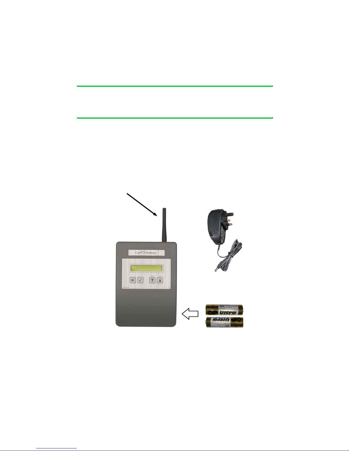
The Light Symphony base-station is a wireless device. This means it receives
commands from the remote control and is able to send control ’messages’ to the
lighting modules in the garden using its antenna only. No electrical connection is
required except the 9V power adapter.
Before installing the base-station, the antenna must be screwed in place on top of the
unit, as shown here
3
Section 1
Installation
Installation
Install 2 x ‘AA’
Long-life batteries for
clock back-up
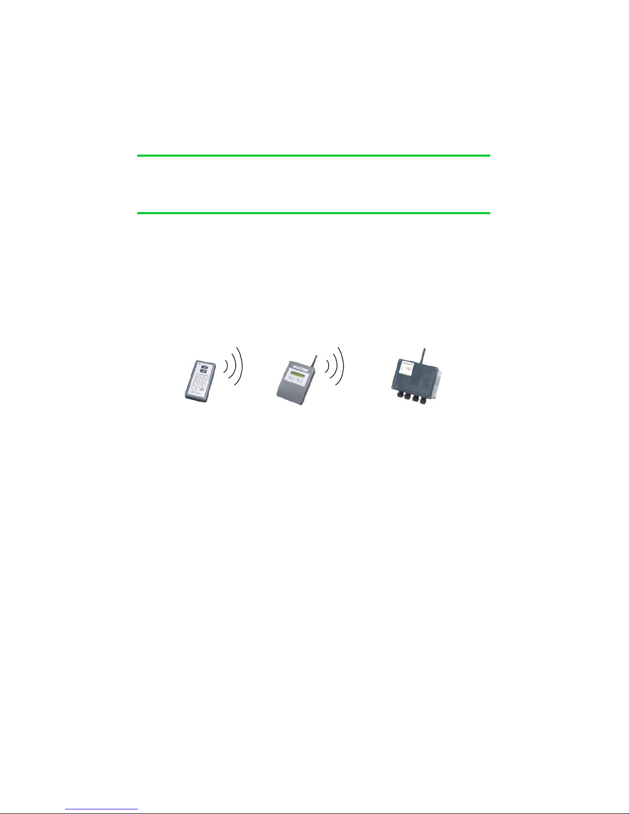
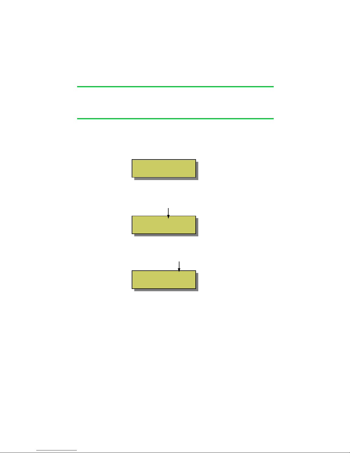
Locating the base-station in the best position is important and the diagram below
shows why. A key function of the base-station is to ‘echo’ commands received from
the remote control(s) to the garden. This creates a very reliable system because the
base-station and Lighting Control Modules don‘t move, which makes the signal-path
constant and therefore consistent, meaning it will always work!
Remote Base Lighting Control
control Station Module
For the base-station’s signal to reach the outdoor ‘Lighting Control Modules’, it
should be located somewhere that gives good radio coverage of the garden. The
base-station is not water-proof and so must be fitted indoors, but try to fit it where it
has the best ‘radio-view’ to the garden i.e. with as few obstacles in the way as possible, such as buildings and walls.
Radio signals do pass through most non-metallic materials but the thicker they are
the more signal is lost. As a rough guide, each standard cavity-wall will reduce the
range by 50% (1000M to 500M). Radio signals do not pass easily through metallic
obstacles such as reinforced concrete or garage doors, and significant range will be
lost.
The base-station does not need day-to-day attention, so it can be fitted in a discrete
location. An example is a loft-space, since the roof usually gives a good radio-view
of the front and back garden.
If ‘Repeater’ units are included in the installation, please pay special attention to the
radio link between the base-station and the repeaters, as detailed in the instructions
for these units.
Section 1
Installation
Location
Section 2
Initial Setup
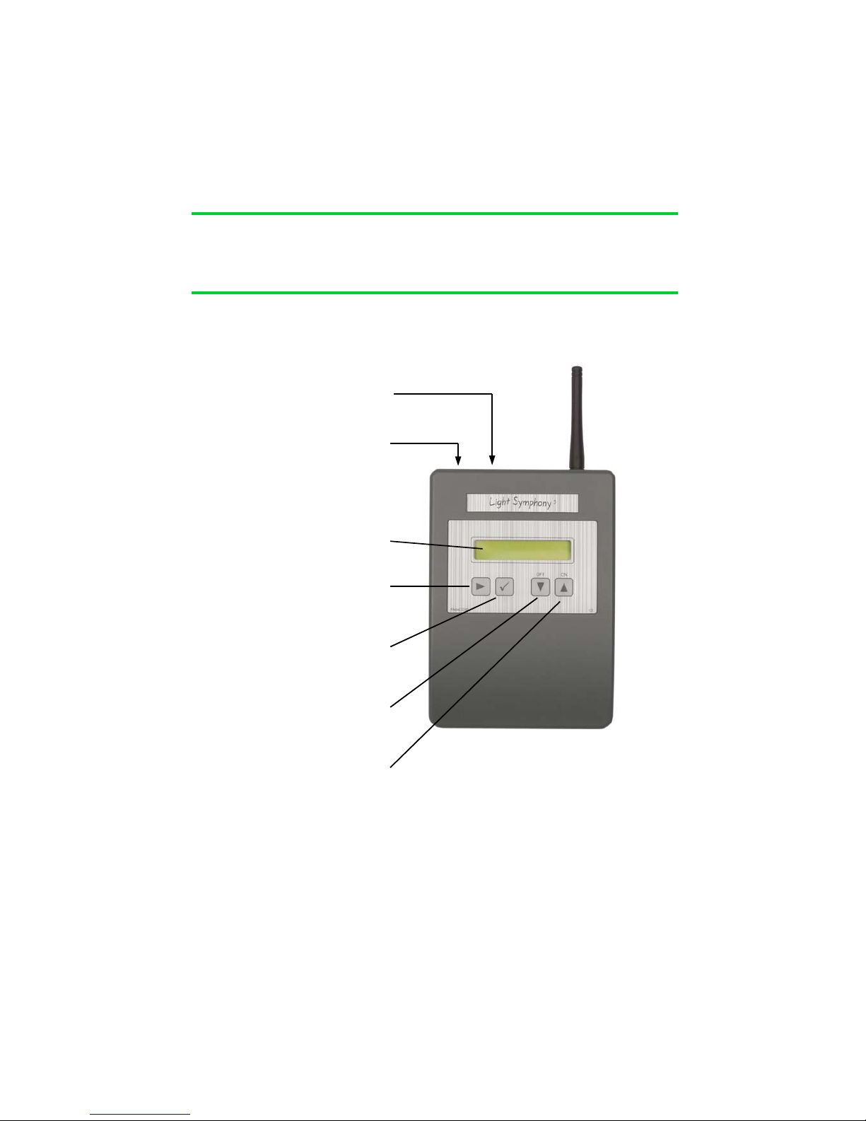
Front Panel
9VDC Power
Interface Port
Serial interface
LCD Display
NAVIGATE
Navigates the menu
OK / STORE
Store settings
DOWN key
(All Area’s OFF)
UP key
(ALL Area’s ON)
5

Section 2
Initial Setup
Navigating The Menu
The base-station has many functions but all are easily configured from the simple keypad. The list below shows all the configurable options in the order in which they are
displayed;
1 Set Time / Date
2 Set Location
3 Set Dusk / Dawn
4 Set Timer 1
5 Set Timer 2
6 Set Timer 3
7 Set Timer 4
8 Set Timer 5
9 Set Timer 6
10 Set External Input
11 Set Light Show
12 Set System Code
13 Set Role
14 Set Protocol
15 WiFi Status
16 Configure WiFi
17 Quit no changes.
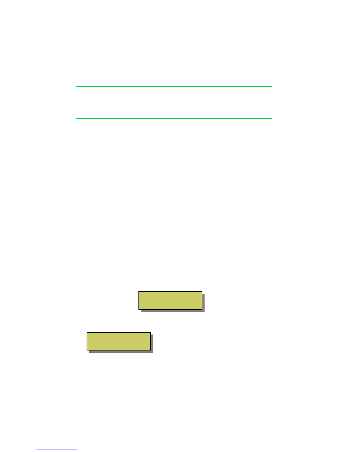
To enter the menu press the navigation key “” once. The display will change to show
The display shows menu line 1 from the list above, use the UP and DOWN keys to
move to other menu options and then press “9” to select. After 30 seconds of no
activity the display will return to the clock.
6
Press 9 to
Set Time/Date
Section 2
Initial Setup
Setting the Time / Date
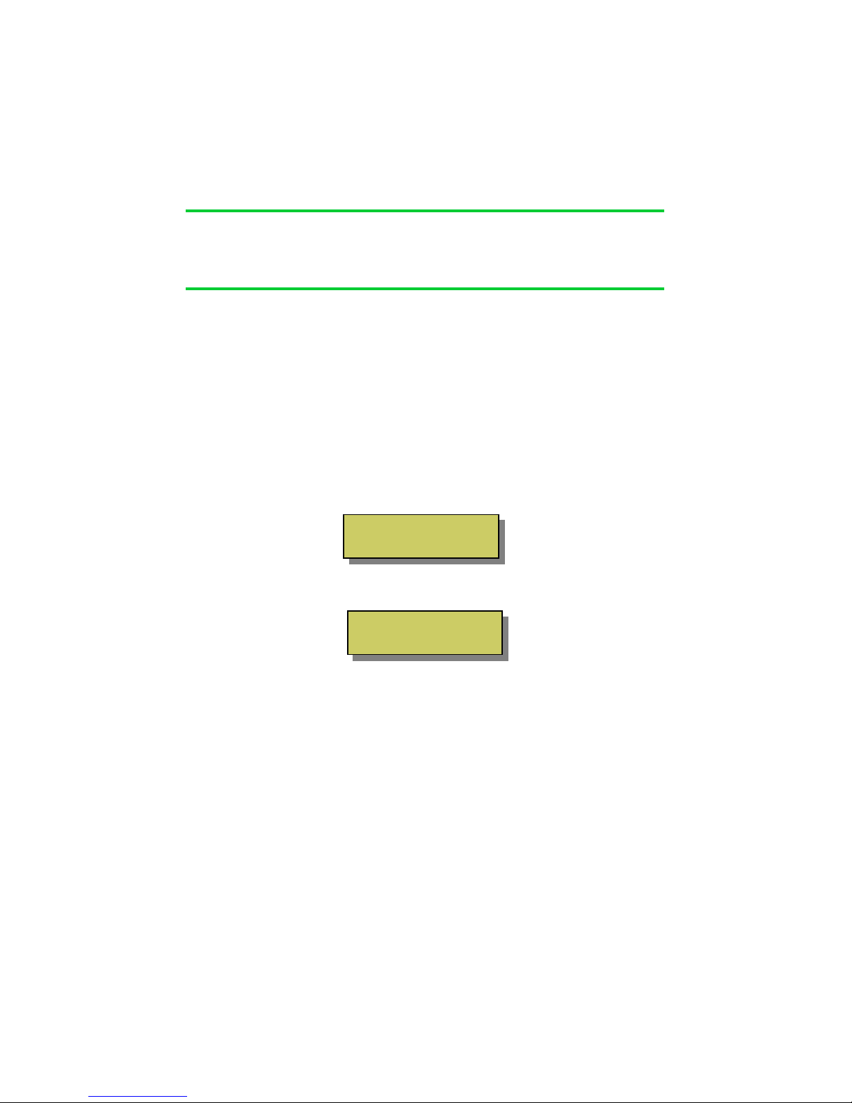
Navigate to the time/date menu by pressing the “” key once. The display will
change to show ...
Press the “9” key to enter the Time/Date menu. The display will change as shown
below. The ‘hours’ will be blinking and may be adjusted to the correct time with the
UP and DOWN keys
.
Once set, press the “” key once and then adjust the minutes to the correct time, as
show below.
Step through each setting using the “” key until the time and date are set, then
press the “9” key to exit the set-up and return to the main display.
The base-station will automatically keep track of summer and winter daylight saving
time. If fitted with good quality ‘AA’ batteries, the clock will be maintained during
power-cuts for several years (see page 3).
7
Press 9 to
Set Time/Date
Time: 00:01
Thu 01 JAN 2010
Time: 16:01
Thu 01 JAN 2010
Dusk / Dawn Time & Location
The base-station includes an astronomical clock which calculates Dusk and Dawn
times throughout the year. This can be useful for setting timers; for example you may
like the lighting to switch on (as it gets dark) at dusk, and switch off again at 11pm.
In this case, the ‘on’ time will automatically adjust throughout the year to match
seasonal daylight hours.
Dusk and Dawn times vary slightly depending on your location. For example, sunset
(dusk), in the winter months, is a few minutes earlier in the north of the country than
in the South. Therefore the base-station can be tailored to a specific location to ensure the dusk and dawn times are calculated as accurately as possible.
By default, the base-station assumes its location is Birmingham, which will give
reasonably accurate results for the whole of the UK (+/-5 minutes).
However, if you wish to improve on this, then navigate to the “Location” menu and
select a town nearest to you.
Setting Location
Navigate to the ‘Location’ menu by pressing the “” key once then pressing the
DOWN key once. The display will change to show ...
Press the “9” key to enter the ‘Location’ menu. The display will change to show...
Navigate by pressing the “” key to
select and adjust the Region and town
nearest you. Press the “9” key when
done to store and exit the menu.
8
Section 2
Initial Setup
Reg England
Nr. Birmingham
Press 9 to
Set Location
Section 2
Initial Setup
8
8
Setting Dusk / Dawn Time
Although the base-station calculates the precise dusk and dawn times for your location,
you may prefer your lighting to come on slightly before sunset (dusk) or slightly after.
Similarly, you may prefer the lights to go off just after sunrise (dawn) or just before.
You can easily modify the Dusk and Dawn times to suit your preference using the
Dusk/Dawn menu.
Navigate to the ‘Set Dusk/Dawn’ menu by pressing the “” key once then pressing
the DOWN key twice.. The display will change to show …
Press the “9” key to enter the ‘Dusk/Dawn’ menu. The display will change to show…
Use the UP / DOWN keys to modify the DAWN time.
Use the “” key to select the DUSK time and adjust in the same way.
Press the “9” key when done to store and exit the menu
9
DAWN: 07:59 +00min
DUSK: 16:21 +00min
Press 9 to
Set Dusk / Dawn

The base-station contains 6 powerful and independent timers. Each timer may be
configured separately to control different aspects of your garden.
The timers can be used to control an individual ‘Area’ of your garden or the whole
garden together (ALL).
It’s also possible for several timers to control the same lighting ‘Area’. For example
Timer 1 can be set to switch all lights ON at Dusk and OFF at 11pm. Timer 2 can be
set to switch all lights ON (again) at 4am and OFF at Dawn.
Each timer can be configured in one of three modes;
‘Every Day’ - Will operate 7 days a week
‘Weekends’ - Will only operate on Saturday and Sunday
‘Week Days - Will only operate Monday – Friday
Using this feature, different lighting effects can be programmed for different times of
the week.
All 6 timers are set-up in the same way, so only Timer 1 is illustrated here.
Setting Timer 1 (to 6)
Navigate to the ‘Timer 1’ menu by pressing the “” key once and then press the
DOWN key 3 times. The display will change to show ...
10
Section 3
Timer Setup
Introduction
Press 9 to
Set Timer 1

Setting Timer 1 (to 6) ...continued
Press the “9” key to enter the ‘Timer 1 (to 6)’ menu. The display will change to
show…
Use the UP / DOWN keys to choose the timer ‘type’ you prefer from the list on page
10 and then press the “9” key to see the Timer’s settings shown below;
ON TIME OFF TIME
‘AREA’ to be controlled
Use the UP/DOWN keys to adjust the ‘On-Time’ hours. You will notice as you
adjust past 00 the time changes to show ‘DUSK’. Using the Dusk setting will
automatically adjust the on-time each day to suit the calculated sunset time.
Next, use the navigation key “” to select the ‘Off-Time’ and set to your preference.
Again, you will notice as you adjust the hours past 00 the off-time changes to show
“DAWN”. Using the Dusk setting will automatically adjust the off-time each day to
suit the calculated sunrise time.
Lastly, use the navigation key “” to select the ‘Area’. The default is “ALL”, which
means the timer will control the whole garden together. You can use the UP /
DOWN keys to change this to a specific ‘Area’ from 1 to 9, which correspond to the
same area’s programmed on the remote control.
Press the “9” key when done to store and exit the menu.
11
Section 3
Timer Setup
Timer Type
Every Day
00:00 to 00:00
Area: All

Setting Timer 1 (to 6) ...continued
It is also possible to configure the timer for a specific length of time. For example,
to switch on at sunset (Dusk) for 3 hours. In this example, since the on-time changes
throughout the year, the off-time will track these changes ensuring the lights are
only on for 3 hours.
To use the timer in this way, simply navigate to the ‘to’ part of the display and use
the Up/Down keys to change it to ‘for’, as shown below
Next, use the navigation key “” to select the ‘on-hours’, which can be adjusted
using the Up / Down keys in 0.5hr steps from 0.5 to 6 hours.
Press the “9” key when done to store and exit the menu.
12
Section 3
Timer Setup
DUSK for 3hrs
Area: All

Section 4
Colour Light Show
Colour Light Show
The base-station is the control hub for Light Symphony’s Colour Light Show.
The Light Show is for controlling colour RGB (red/green/blue) lights and can
wirelessly synchronise the speed, timing and colour of any number of LEDs. To setup a ‘Light Show’ the RGB controller(s) must be included in a lighting Area (zone).
For example: to include a RGB lighting controller in say ‘Area 8’, simply double-tap
the RGB controller to switch it on, then press the ‘Area 8’ key on the remote control
to store it. The RGB controller will beep and, if the LEDs were ON at the time, they
will now be stored in that Area. (to remove a controller from an Area, double-tap
until the LEDs are off
then press the Area key).
Next, set the Base-Station’s Light Show to the same Area. e.g. no. 8 (see page 14).
The Light Show will run whenever Area 8 (or your chosen Area) is switched on. The
light show will also be started by the remote control’s ‘Garden On’ button or any
timer set to control the same Area.
The light show will gently fade between the range of colours selected, including ALL
(16 key colours), WARM (red, orange, yellow etc), COOL (blue, violet, white etc),
RGB (red, green and blue only) or PASTEL.
The ‘speed’ of the light show can be controlled from 3 to 60 second intervals. For
example, if the show is set to step every 60 seconds, the colour will change very
gently over a 60 second period. Like the slow moving minute-hand on a clock, this is
barely perceivable and therefore creates a very subtle and pleasing effect.
Any non-RGB lighting controllers included in the Light Show Area will not be
effected by the show but will still switch on and off with the Area.
13

Colour Light Show set up
To configure the Light Show to your preference, navigate to the ‘Set Light Show’
menu by pressing the “” key then pressing the DOWN key ten times. The display
will change to show;
Press the “9” key to enter the Light Show set-up;
Use the Up/Down keys to select the Area to be controlled by the Light Show. Next
press the “9”, the display will briefly show “STORED” and then display;
Use the “” navigation key to select the time and colour options and use the Up/
Down keys to adjust them.
Select between time intervals of 3, 5,10, 20, 30 and 60 seconds.
Select between; None (white light), All (any colour), Primes (primary colours only),
Warm (reds, oranges etc), Cool (blues, violets etc) or Pastel colours.
Press “9” to STORE the settings and exit the menu. Note; these settings can be
adjusted via the smart phone app but the changes will not be stored.
14
Section 4
Light Show
Press 9 to
Set Light Show
Speed : 5 sec
Colour : None
Light Show
Area : 8

Section 5
Interfacing – Advanced Setup
Introduction
The base-station provides several interface options allowing connection to third party
equipment.
1. Digital Trigger Input
2. Serial Port*
3. WiFi Network*
*NOTE
The serial port and Wifi interfaces are only
available on the WiFi version of the base-station
Digital Trigger Input
The base-station includes a low-voltage trigger input which may be used to trigger
the lighting. It can be useful for interfacing to an external sensor such as a light
beam across a drive-way , PIR motion sensor or even an alarm panel so the lighting
is triggered with the alarm.
The trigger input is rated maximum 5Volts, so a relay is usually required as shown
below;
15
RELAY
COIL
5V TRIGGER
INPUT
5V SUPPLY
Pin 8 = 0V
TRIGGER
VOLTAGE
Base-Station
Interface
8 7 6
5 4 3
2 1

Digital Trigger Input
The digital input may be configured in a number of modes;
1 On / Off
2 Trigger
3 If Timer 1-5
4 If Dusk
On / Off Mode
In this mode, the lighting will switched ON when the trigger input is activated
and switched OFF when the trigger input is de-activated. This allows interfacing
to a simple, external on/off type switch.
To configure the external input in on/off mode configure the menu like this;
16
Section 5
Interfacing – Advanced Setup
1 2
3 4 5
6 7 8
Base-Station
Interface
On / Off Switch
Ext : On / Off
Area: All
Press 9 to
Set Ext Input

Digital Trigger Input ...continued
Trigger Mode
In trigger mode, the lighting is switched ON for a pre-set time when the trigger
input is activated. This allows interfacing to a sensor or bell-push type switch, where the
lighting must be triggered for a pre-set time and then automatically switched off again.
To configure the input to respond to a trigger, set the menu like this;
‘If Timer’ Mode
In ‘If Timer’ mode, the lighting will over-ride the setting of a Timer, but only if the
timer is active. For example, if Timer 1 is set to switch on Area 1 from Dusk to 11pm,
the digital input will be ignored outside these times.
This feature can be useful in a gate or drive-way application, where the lights are timed
to be on but kept at a low level (e.g. Area 1’s setting). When triggered by a car, the
lights can fade to full brightness (e.g. Area 2’s setting) for a pre-set time. At the end of
the triggered time interval, the lights will not switch off, but revert back to the Timer’s
setting (Area 1’s setting).
To configure the input to respond to a trigger with a Timer, set the menu like this;
‘If Dusk’ Mode – Works as ‘Trigger’ mode but only active between Dusk & Dawn
17
Section 5
Interfacing – Advanced Setup
Ext : Trigger
Area: All >3min
Press 9 to
Set Ext Input
Ext : If Timer 1
Area: 2 >10min
Press 9 to
Set Ext Input

Serial Port
The serial port can support a number of different protocols to simplify interfacing to
third party equipment.
The port is bi-directional for handshaking purposes, but only allows control ‘input‘,
i.e. Light Symphony can not be used to transmit its status back to a host controller.
The following RS232 protocols are supported at this time;
1 Ascii Baud rate; 300, 1200, 4800, 9600 19200
2 Lutron Baud rate; 300, 1200, 4800, 9600 19200
In both cases the format is 8 bits, with 1 start, 1 stop bit (no parity)
Commands received over the serial port over-ride any user or internal (timed)
events.
Serial Pin-Out
To configure the serial port select the protocol menu shown below;
18
Section 5
Interfacing – Advanced Setup
1 2
3 4 5
6 7 8
Base-Station
Interface
RS232 RS485/422
Pin 3 – Tx Pin 3 – TxPin 5 – Rx Pin 4 – Tx+
Pin 7 – Gnd Pin 5 – Rx Pin 6 – Rx+
Protocol Speed
Ascii 9600
Press 9 to
Setup Protocol

Serial Port … continued
ASCII Interface
The port expects simple lower-case ASCII messages in the format below;
Lutron® Interface
The serial port can be configured to support Lutron’s ® GrafikEye serial protocol.
To select the Lutron protocol, configure the protocol screen like this;
19
Section 5
Interfacing – Advanced Setup
Message Action
all_on Switch ON all areas
all_off Switch OFF all areas
area_on x Switch ON area ‘x’, where x = “0” to “9”
area_off x Switch OFF area ‘x’, where x = “0” to “9”
start-show Start light-show running
stop_show STOP light show
inten_x Set intensity of last selected area to ‘x’
where x = “0” to “9”
Protocol Speed
Lutron 9600
Press 9 to
Setup Protocol

Section 5
Interfacing – Advanced Setup
Serial Port … continued
Lutron® Interface
To interface a Lutron GrafikEye ® to the base-station an RS232 interface is required
for the GrafikEye system. Lutron’s RS232 interface unit must be used as shown;
The GrafikEye is a ’Scene’ controller. When a Scene is selected it will set all the
lighting to a pre-stored level. For ease of use, it is recommended that Light
Symphony is also configured as a Scene controller (as opposed to Area/Zone
switching) when interfacing with Lutron.
Normally only Lutron 4 Scenes are available although this will depend on the design
and configuration of the Lutron system.
Each GrafikEye has a unique communication ‘Address’ in the range 1-8. The Light
Symphony base-station must be configured to the address of the GrafikEye unit that
will control it, normally “01”.
After selecting the Lutron protocol (see below) , press the “9” key to configure the
Lutron Address;
20
Luton RS232
Interface
Lutron Control
Unit Address 01
Protocol Speed
Lutron 9600
Lutron Address

Serial Port … continued
Lutron® Interface
The base-station allows Lutron Scene’s to be ‘linked’ to Light Symphony’s ‘Areas’,
which can be used as scenes memories too. For example, activating Lutron Scene 1
will cause Light Symphony Area (scene) 1 to also be activated. Similarly, a Lutron
‘Off’ command will generate a garden-Off command.
By default, the base-station is set-up to link Lutron’s scenes 1-4 to Light
Symphony’s Areas 1-4;
After setting the Lutron ‘Address’ (see previous page), press the “9” key to
configure the ‘links’ between the Lutron Scenes and Light Symphony Area’s, see
table above. By adjusting these settings, any of Light Symphony’s 9 Area’s (Scenes)
can be triggered by any of Lutron’s Scenes.
21
Lutron Scene Light Symphony ‘Area’ (Scene)
1 1
2 2
3 3
4 4
Section 5
Interfacing – Advanced Setup
Scene 01
Area 01
Lutron Control
Unit Address 01
LINK / TRIGGER

WiFi Interface
The WiFi version of the base-station includes a 802.11b/g standard interface that is
able to connect to an existing wireless network or operate stand-alone in ‘Ad-hoc’
mode. This interface is designed for use with Apple’s iPhone® or iTouch® and the
free ‘iSymphony’ application for these devices can be downloaded from Apple’s
iTunes web store.
To configure the WiFi interface press “9” at this menu;
Join an Existing WiFi Network
The base station can join an existing WiFi network either by searching for it or
entering its SSID using the menu options above.
Once a network has been found, the security password must be entered.
22
Section 5
Interfacing – Advanced Setup
Press 9 to
Configure WiFi
Press 9 to
Scan WiFi
Press 9 to
Enter SSID
Press 9 to
Ad Hoc Mode
Then press Up / Down to
select from the following...
Scan for available WiFi networks
Enter SSID for a WiFi network that hides
its SSID (doesn't broadcast its SSID)
Start Ad-Hoc mode to create stand-alone
network

Section 5
Interfacing – Advanced Setup
WiFi Interface … continued
Join an Existing WiFi Network
After a scan, the base-station will show a list of available networks, press the “9” key to
join one;
Next the security password must be entered or passphrase. Use the Up/Down keys to
select a character (take care to enter upper and lower case characters correctly) then
move to the next character using the “” key.
If you key a wrong character by mistake, use the Up/Down keys to select the backspace
character “←” and click the “” key to erase it.
Once the last character is keyed, press the “9” key. The base-station will attempt to join
the network. This may take up to 60 seconds, and the display will show “Connecting…”
and then will change to either show;
NOTE: The base-station will request an IP address from the network’s DHCP server. If
no DHCP server can be found the unit can not work. It is not possible set a manual IP.
23
Select Network
some_network_name
Passphrase
A
WiFi Status
Connected OK
WiFi Status
Auth Fault
Successfully joined WiFi
network and ready to be used
Unable to join WiFi network
Please try again.
OR

WiFi Interface … continued
Create an Ad Hoc WiFi Network
If an existing WiFi network does not exist then the Ad Hoc mode can be used to
allow devices to connect directly to the base-station.
To start the ad-hoc mode press the “9” key at this menu;
The base-station will then show…
This procedure can take 60 seconds to complete.
The base-station’s Ad Hoc network has the SSID “LightSymphony”
A WiFi enabled device can now connect to the LightSymphony network.
Once a connection has been established the WiFi signal level (SL) and signal
quality (SQ) can be viewed using the menu below. Please note, the base-station
will not process WiFi commands while this menu is displayed!
24
Section 5
Interfacing – Advanced Setup
Press 9 to
Ad Hoc Mode
Connecting...
WiFi Status
Starting Ad Hoc..
WiFi Status
Connected OK
Connected OK
SL/SQ 75% / 90%
Press 9 to
WiFi Status

Section 6
Security
System Code
The Light Symphony system has a potential wireless range of several Kilometres
(using repeater units) so it is important to avoid interference with neighbouring
systems. For this reason a ‘System Code’ is employed which can be set from 1 to
32. Systems set with different codes will not interfere with each other.
The Lighting Control Modules adopt the System-Code from the remote control
that is used to program them. By default the Remote control System-Code is set to
1, but can be changed by following the instructions that came with it.
If the Remote-Control and therefore Lighting Control Module’s System-Code has
been changed then the base-station must be configured to match.
Press the “9” key to enter the ‘Set System code’ menu. The display will change;
Adjust the System Code with the Up / Down keys and press the “9” key to store
and exit.
25
System Code 01
Press 9 to
Set System Code

Section 6
Security
Wireless Repeaters
Light Symphony allows up to 5 ‘repeaters’ to be used together to greatly increase the
wireless range and reliability of the system. Each repeater will ‘echo’ wireless
commands sent from any of the transmitter units such as the Remote Control, TouchScreen or Wall Switch. This ensures commands reliably reach all the Lighting
Control Modules.
The base-station includes a repeater and is always the first repeater in the system
(repeater #1). Where more repeaters are added, each must be assigned its own unique
number (2 to 5). For guaranteed reliability, each repeater (including the base-station)
must be within radio range of the adjacent numbered repeater.
Failure to build a system with this wireless connectivity may prevent the
repeaters from reliably relaying commands.
Extra base-stations may be installed on a system and used as repeaters, but each must
be assigned a unique repeater number. The menu “Set Role” provides this option. If a
base-station is configured as a Repeater, then all other functions are disabled;
26
Base Station
(Repeater #1)
Repeater Repeater Repeater Repeater
#2 #4
Needs Reliable Wireless Link
Role
Repeater 2
Press 9 to
Set Role
#3 #5

How it works
Sometimes an understanding of how a system works can greatly assist in learning its
abilities.
Light Symphony is a radio (wireless) lighting system. The remote control transmits a
wireless signal when a button is pressed, which the outdoor Lighting Control Module
receives and in turn switches the lighting circuit.
The remote control sends on/off command-codes from 0 to 9, which are referred to as Areas. Area code 0 is a special case and used as a master on/off for the whole garden. Each
Lighting Control Module (receiver) can be configured to respond to Area codes 0 to 9 or to
ignore them. This allows groups or zones of circuits to be assigned to each Area key on the
remote control. By default, all Lighting Control Modules will respond to master on/off
commands (Area 0) , although this too can be changed.
The Lighting Control Modules allow two different types of system to be created. In a small
garden, it makes sense to simply assign each lighting circuit to an Area key on the remote,
thereby offering the client full control of each circuit. The 9 (+all) area codes provide up to
9 individual channels of control.
For larger projects, with more than 9 circuits, individual control becomes confusing, so
Light Symphony allows circuits to be grouped into zones or scenes. The remote control’s
area keys can now be used to select sections of the garden (zones) or recall a complete
lighting mood (scene). The number of controllable lighting circuits is limited only by the
number of Lighting Control Modules in the system.
The system’s wireless range is improved by the use of repeaters, which echo any
commands received from any of the transmitters. Up to 5 repeaters may be installed each
with a range of 1 Kilometre. The repeaters are assigned number codes and will echo
received commands in sequence based on this code. To avoid repeaters interfering with
each other and to ensure the commands are echoed by all repeaters, its important that
repeaters are each assigned a unique number and are within reliable wireless range of their
adjacent numbered unit. For example, repeater #3 must be in good range of #2 and #4.
Provided the repeaters are uniquely numbered they cannot interfere with each other, even
if all 5 are in very close proximity.
27
Section 7
How it works

Section 8
Trouble Shooting
*NOTE
The remote control can be tested by watching the base-station display while any button
is pressed on the remote control. If the remote ‘command’ is received, the base-station
will display a message briefly. With two people, the remote’s ‘range’ can be determined
using this test.
28
Symptom Cause Action / Remedy
No lights
working
No ‘On’ command Lights stay off when power applied until an ON
command is sent.
Press Garden On using the remote control
No Power to lights
Check 230V supply to light circuit
No Power to Indoor Control
Unit
Check Indoor Unit, LCD display is on and buttons
operate as expected.
Remote out of ‘range’ Test lights without the remote control using the
ON button at the base-station.
Lights changing
by themselves
‘Light Show’ is running Press ALL ON or ALL OFF to stop the show.
Battery low/missing/wrong Check the red LED blinks strongly on the remote
control when any b utton is pressed. If not check
batteries are good and fitted correctly.
Out of ‘range’* Maximum range can be under 100m
indoors. To check remote, stand next to a Lighting
Control Module outside.
Radio Interference* Other wireless equipment causing interference
such car/house alarm, police radio, mobile phone.
iPhone not working
Wifi Status or Config menu is
displayed
Press “9” key to exit menu and return to clock
display
Remote Control Handset
‘Dead’

Section 9
Safety
• The Light Symphony system is a 230 Volt system and should be installed by a
qualified electrician with up-to-date knowledge of current electrical safety legislation and safe working practices.
• Installation work must be carried out to national electrical wiring regulations.
• The whole
system must be powered through a suitably rated earth leakage circuit
breaker and fuse / MCB, based on the total lighting load.
• The system operates with a continuous supply to all the lighting control modules
and may appear ‘dead’ even when the supply is ‘LIVE’, BE CAREFUL and always
isolate the supply before working on the system.
• Always isolate the power before replacing blown lamps and ensure the end-user is
trained to do the same.
• Read the safety instructions that are supplied with each light fitting or any other
product being installed to the system.
• All external cabling must be of ‘Concentric’ type if above ground.
• Buried cables must be ‘Steel Wire Armoured’ and at least 450mm (18”) below
ground.
• BURN HAZARD: Some lamps / light fittings get very hot during normal use. Be
careful not to touch hot parts and keep children away.
The installation should be carried out by a qualified electrician and basic electrical
knowledge is assumed. If you are not in this category or are unsure about any aspect of
the installation work seek the help of a qualified installer – do not take chances,
electricity can kill.
29
Safety Warnings

Section 10
Specifications
All Models ( LS30900BSR & LS30950WIFI )
Supply Voltage 9VDC (regulated) 250mA via adaptor
Power Consumption 2W (250mA)
Individual Control Unlimited lights, power permitting
Control Method RF Low-power FM radio
Radio 434.075MHz, 25mW, Narrow Band FM
Protocol Light Symphony
RF Range 1000Meters, line-of-sight
Battery Back-up 2x ‘AA’ size, non-rechargeable battery
Digital Trigger Input 5VDC Level with 2K input impedance.
Weight 0.7Kg with PSU
Size 120mm x 240mm x 50mm
Electrical Safety Low-voltage, isolated device requiring
no special electrical precautions or earth
EMC emission/immunity EN 50081 - 1/ To EN 50082 – 1
Electrical safety EN 60950 en 60065
Radio EN 300-220
Ambient temperature 0°C to +40°C (operation)
Compliance CE
WiFi Model Only ( LS30950WIFI )
Serial Port RS232 / RS485 compatible (s/w selectable)
Serial Protocols Light Symphony ASCII & Lutron
Serial Format Baud adjustable 300-19200, 8 bit,
1 start, 1 stop bit.
WiFi 802.11/b/g with internal antenna
Control Protocol Socket UDP, requiring external DHCP
Modes WiFi Client or Ad-Hoc
30

COPYRIGHT (C) PM INTERNATIONAL LTD 2012 VERSION 4.0
Environmental Information for Customers in the European Union
European Directive 2002/96/EC requires that the equipment bearing this symbol on the
product and/or its packaging must not be disposed of with unsorted
municipal waste. The symbol indicates that this product should be disposed of
separately from regular household waste streams. It is your responsibility to
dispose of this and other electric and electronic equipment via designated
collection facilities appointed by the government or local authorities. Correct disposal and
recycling will help prevent potential negative consequences to the environment and human health.
For more detailed information about the disposal of your old equipment, please contact your local
authorities, waste disposal service, or the shop where you purchased the product.
GrafikEye® and Lutron® are registered trade marks of Lutron company.
 Loading...