

Light Stream Controls Auto-Mate/DMX User Instructions
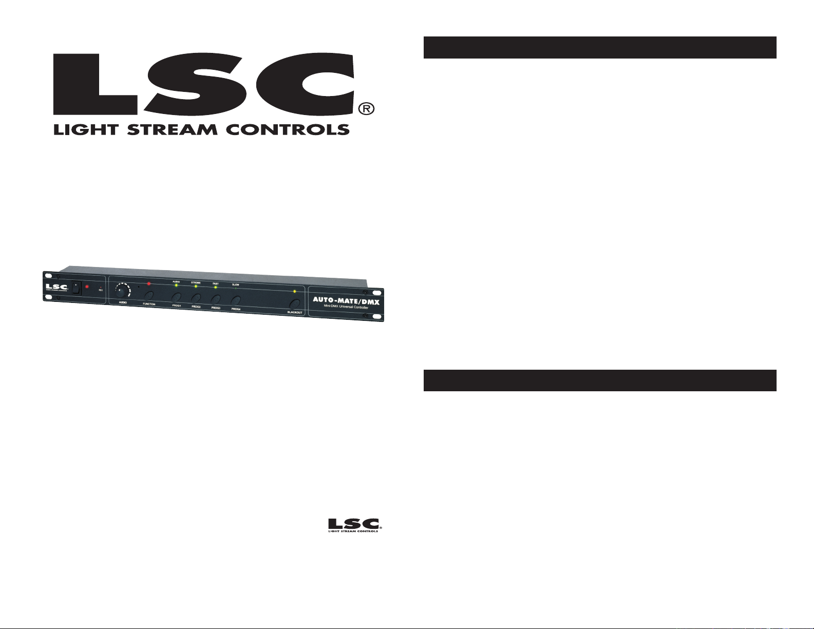
Auto-Mate/DMX™
User Instructions
Auto-Mate/DMX™ Contents
Features..............................................................................2
Introduction.................................................................................3
Safety Precautions........................................................................4
Connection and DMX Setup...........................................................5
Controls and Function..................................................................7
Operation (Plug and Play)...............................................................9
Installing Programs......................................................................10
Activate the Record-Mode............................................................11
Data Exchange.............................................................................12
Set Up Procedures
Mighty Scan.......................................................................13
Max.................................................................................14
Pocket Scan.......................................................................15
X-Calibur........................................................................16
Spiral Scan........................................................................17
Rainbow 250......................................................................18
DJ Scan.............................................................................19
DJ Roller............................................................................20
Cleaning...........................................................................................21
Warranty............................................................................................22
Revised 5/03
Light Stream Controls
4295 Charter Street
Los Angeles Ca. 90058
www.lightstreamcontrols.com
Auto-Mate/DMX™ Features
• 256 DMX Channels
• 8 Chase Programs (4 xʼs 2 banks)
• 60 Scenes per a Program
• Sound Active
• Blackout Mode
• Built-In Microphone
• 19” Rackmount Design
• Capable of Data Exchange
• Programmable
Please Note: Specications and improvements in the design of this
unit and this manual are subject to change without any prior written
notice.
©LSC Supply® - www.lightstreamcontrols.com - Auto-Mate™ Instruction Manual Page 2

Auto-Mate/DMX™ Unpacking
Every Auto-Mate/DMX™ has been thoroughly tested and has been
shipped in perfect operating condition. Carefully check the shipping
carton for damage that may have occurred during shipping. If the
carton appears to be damaged, carefully inspect your controller for any
damage and be sure all equipment necessary to operate the unit has
arrived intact. In case damage has been found or parts are missing,
please contact our toll free customer support number for further instructions, please do not return the controller to your dealer.
Auto-Mate/DMX™ Introduction
Introduction: The Auto-Mate/DMX™ is a Plug and Play DMX Con-
troller with 8 programmed chases (4 slow and 4 fast). It has 256 DMX
channels and each of the 8 Chases Programs can contain up to 60
steps. This unit comes with programmed chases for either the American DJ® Spiral Scan, DJ Scan, DJ Roller, Rainbow 250, Max, Mighty
Scan, Pocket Scan, or X-Calibur. Be sure you have purchased the unit
that comes with programs for your specic xture. All the chases are
designed to operate in conjunction with the Strobe, Fast, Slow, and
Blackout functions. You can also store your own chases on any of the 8
program banks, by using an External DMX controller such as the LSC®
Show Designer.™ Storing your own programs however, will erase any
existing program that is stored in a particular memory bank.
Customer Support: LSC® provides a toll free customer support line,
to provide set up help and to answer any question should you encounter problems during your initial set up or operation. You may also visit
us on the web at www.lightstreamcontrols.com for any comments or
suggestions. Service Hours are Monday through Friday 9:00 a.m. to 5:
30 p.m. Pacic Standard Time.
Voice: (800) 322-6337
Fax: (323) 582-2610
E-mail: support@lightstreamcontrols.com
Auto-Mate/DMX™ Safety Warnings
• Do not spill water or other liquids into or on to your unit.
• To reduce the risk of electrical shock or re, do not expose this unit
rain or moisture
• For adult use only - Keep out of the reach of children.
• Always use a power supply that meets the manufactures exact power
specications
• Be sure that the local power outlet match that of the required voltage
for your power supply.
• Do not attempt to operate this unit if the power cord has been frayed
or broken.
• Disconnect from main power before making any type of connection.
• Do not remove the unit covers under any conditions. There are no
user serviceable parts inside.
• Never operate this unit when itʼs covers are removed.
• Never plug this unit in to a dimmer pack
• Always be sure to mount this unit in an area that will allow proper
ventilation. The appliance should be situated away from heat sources
such as radiators, heat registers, stoves, or other appliances (includ ing amplifiers) that produce heat.
• Do not attempt to operate this unit, if it becomes damaged in any
way.
• This unit is intended for indoor use only, use of this product outdoors
voids all warranties.
• During long periods of non-use, disconnect the unitʼs main power.
• Always mount this unit in safe and stable matter.
• Cleaning -The fixture should be cleaned only as recommended by
the manufacturer.
Caution! There are no user serviceable parts inside this unit. Do not
attempt any repairs yourself, doing so will void your manufactures warranty. In the unlikely event your unit may require service, please contact
LSC® customer support.
Do not discard the packing carton in the trash. Please recycle
when ever possible.
©LSC Supply® - Auto-Mate/DMX™ Instruction Manual Page 3
©LSC Supply® - Auto-Mate/DMX™ Instruction Manual Page 4
POWER
SOUND
REMOTE
CONTROL
INPUT
POWER
INPUT OUTPUT
1
2
3
Terminatio n re duces signal errors and
avo ids signal tran smis sion problem s
and interference. It is always advisable
to connect a DMX terminal, (Resistance
120 Ohm 1/4 W) between PIN 2 (DMX-)
and PIN 3 (DMX +) of the last fixture.
DMX512 IN
3-PIN XLR
REMOTE
CONTROL
INPUT
POWER
INPUT OUTPUT
SOUND
REMOTE
CONTROL
INPUT
POWER
INPUT OUTPUT
SOUND
REMOTE
CONTROL
INPUT
POWER
INPUT OUTPUT
DMX512
DMX+,DMX-,COMMON
1
2
3
Terminatio n re duces signal errors and
avo ids signal tran smis sion problem s
and interference. It is always advisable
to connect a DMX terminal, (Resistance
120 Ohm 1/4 W) between PIN 2 (DMX-)
and PIN 3 (DMX +) of the last fixture.
1
2
3
1
2
3
DMX +
DMX -
COMMON
DMX512 OUT
3-PIN XLR
Auto-Mate™ DMX Set Up
Auto-Mate™ DMX Set Up
Power Supply: Before plugging your unit in, be sure the source volt-
age in your area matches the required voltage for your LSC® Auto-Mate/
DMX™ power supply. Connect the Auto-Mate/DMX™ to a main power
supply using the included 12v AC power supply only. The LSC® AutoMate/DMX™ is available in a 120v and 220v version. Due to variations
in line voltage from venue to venue, be sure to plug your power supply
into a wall outlet with matching power before attempting to operate.
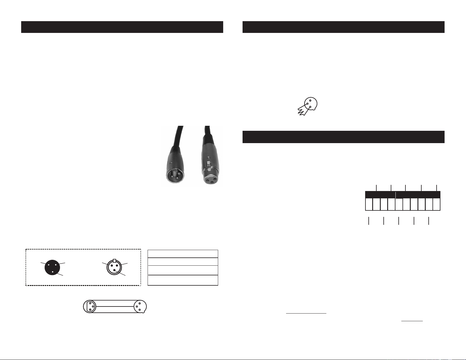
Data Cable (DMX Cable) Requirements: Connect the Auto-Mate/
DMX™ and your xtures together using standard 3 pin DMX cables
(Figure 1). The Auto-Mate/DMX™ uses DMX-512 protocol to operate
your xtures. If you are constructing your own data cables, be sure to
use standard two conductor shielded cable (This
cable may be purchased at almost all professional sound and lighting stores). Your cables
should be made with a 3-pin male and female
XLR connector on either end of the cable. Also
remember that DMX lines must be daisy chained
and can not be split.
Notice: Be sure to follow gures two and three
when making your own cables. Do not use the ground lug on the XLR
connector. Do not connect the cableʼs shield conductor to the ground
lug or allow the shield conductor to come in contact with the XLRʼs outer
casing. Grounding the shield could cause a short circuit and erratic
behavior.
©LSC Supply® - www.lightstreamcontrols.com - Auto-Mate/DMX™ Instruction Manual Page 5
XLR Male Socket
1 Ground
Figure 2
2 Cold
3 Hot
2 Cold
XLR Female Socket
1 Ground
3 Hot
Figure 1
XLR Pin Conguration
Pin 1 = Ground
Pin 2 = Data Compliment (negative)
Pin 3 = Data True (positive)
Figure 3
Special Note: Line Termination.
When longer runs of cable are
used, you may need to use a terminator on the last unit to avoid erratic
behavior. A terminator is a 90-120 ohm 1/4 watt resistor which is connected between pins 2 and 3 of a male XLR connector (DATA + and
DATA -). This unit is inserted in the female XLR connector of the last
unit in your daisy chain to terminate the line. Using a cable terminator
will decrease the possibilities of erratic behavior.
Figure 4
Auto-Mate™ DMX Addressing
DMX is short for Digital Multiplex. This is a universal binary language
used as a form of communication between intelligent fixtures. Each dip
switch represents a binary value.
Dip Switch 1 address equals 1
Dip Switch 2 address equals 2
Dip Switch 3 address equals 4
Dip Switch 4 address equals 8
Dip Switch 5 address equals 16
Dip Switch 6 address equals 32
ON
Dip Switch 7 address equals 64
Dip Switch 8 address equals 128
Dip Switch 9 address equals 256
Dip Switch 10 address equals 512 This switch is sometimes used to activate a fixtures special functions.
DMX CHANNEL
1282 8 32
1 98765432
256651641
A DMX value (address) is set by combining the different dipswitches
that will add up to the value you wish to achieve, for example:
Setting DMX address for 21. Set DMX address for 201.
Flip switches 1, 3, & 5 to the Flip switches 1, 4, 7, & 8 to the
“ON” position “ON” position
1 =1 1 = 1
3 = 4 4 = 8
5 = 16
Dipswitches # ValueValueDipswitches #
7 = 64
= 21 8 = 128
= 201
©LSC Supply® - www.lightstreamcontrols.com - Auto-Mate/DMX™ Instruction Manual Page 6
SP
10
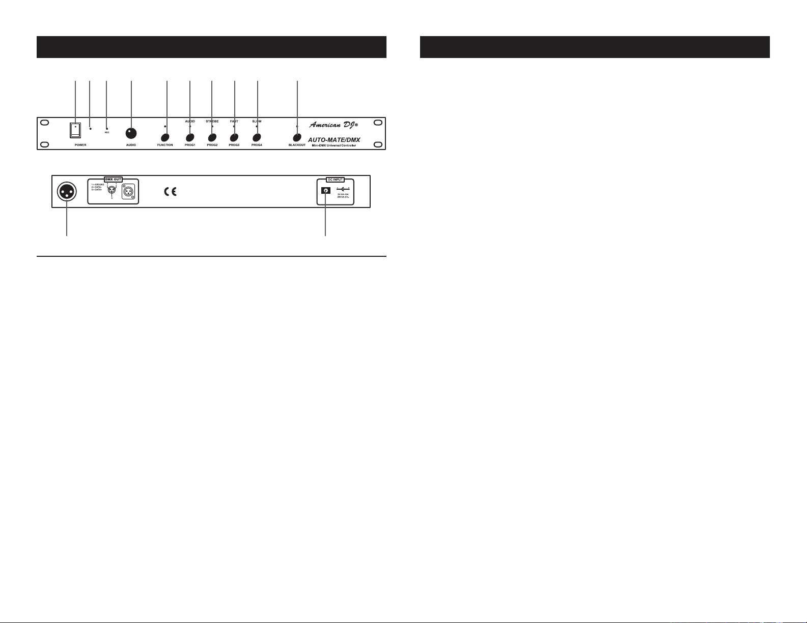
Auto-Mate/DMX™ Controls and Functions Auto-Mate/DMX™ Controls and Functions
1 1098765432
1211
1. Power Switch -
This switch turns on the unitʼs main power.
2. Power Indicator -
This yellow LED will glow when main power is activated. This LED will
ash briey when program mode is activated.
3. Microphone -
The unit comes with a built-in microphone designed to pick-up on low
frequencies. The unit then uses this signal to trigger program succession.
4. Audio Sensitivity Knob -
This knob is used to adjust the unitʼs sensitivity to sound. When the
knob is turned in a clockwise direction, the unit becomes more sensitive to sound, when this knob is turned in a counter-clockwise direction
the unit becomes less sensitive to sound. Usually the more sensitive to
sound the unit is, the faster the programs will chase.
5. Function Button -
This button is used to change the functionality of the Audio/Prog 1,
Strobe/Prog 2, Fast/Prog 3, and Slow/Prog 4 Buttons. Engaging the
function button will allow the “Audio,” “Strobe,” “Fast,” and “Slow” modes
to operate. The red function LED will glow when function level two is
active.
6. Audio/Prog 1 Button -
This button serves two functions. When the function level two is
engaged, this button will activate sound-active mode. When the function
level one is engaged, selecting this button will active the program stored
in this bank.
7. Strobe/Prog 2 Button -
This button serves two functions. When the function level two is
engaged, this button will activate strobe mode. Strobe mode will initiate
a strobe function to any program running. When the function level one
is engaged, selecting this button will active the program stored in this
bank.
8. Fast/Prog 3 Button -
This button serves two functions. When the function level two is
engaged, this button will activate the rst bank of four programs. When
the function level two is engaged, selecting this button will active the
program stored in this bank.
9. Slow/Prog 4 Button -
This button serves two functions. When the function level two is
engaged, this button will activate the second bank of four programs.
When the function level two is engaged, selecting this button will activate the program stored in this bank.
10. Blackout Button -
This button activates blackout mode. In blackout mode all xture actively
will enter into stand-by mode - No light output - No mirror movement.
11. DMX Output Jack -
This jack sends the controllers DMX signal to your xtures. This jack
uses a standard 3-pin XLR female connector.
12. Power Supply Input Jack -
Only connect a recommended power supply AC 9v~12v, 250mA. Use of
a power supply other than a recommend power supply could damage
your unit and will void your manufactures warranty.
©LSC Supply® - www.lightstreamcontrols.com - Auto-Mate/DMX™ Instruction Manual Page 8©LSC Supply® - www.lightstreamcontrols.com - Auto-Mate/DMX™ Instruction Manual Page 7
 Loading...