

Light Sport Aviation EV-97 EUROSTAR SL MICROLIGHT Maintenance Manual
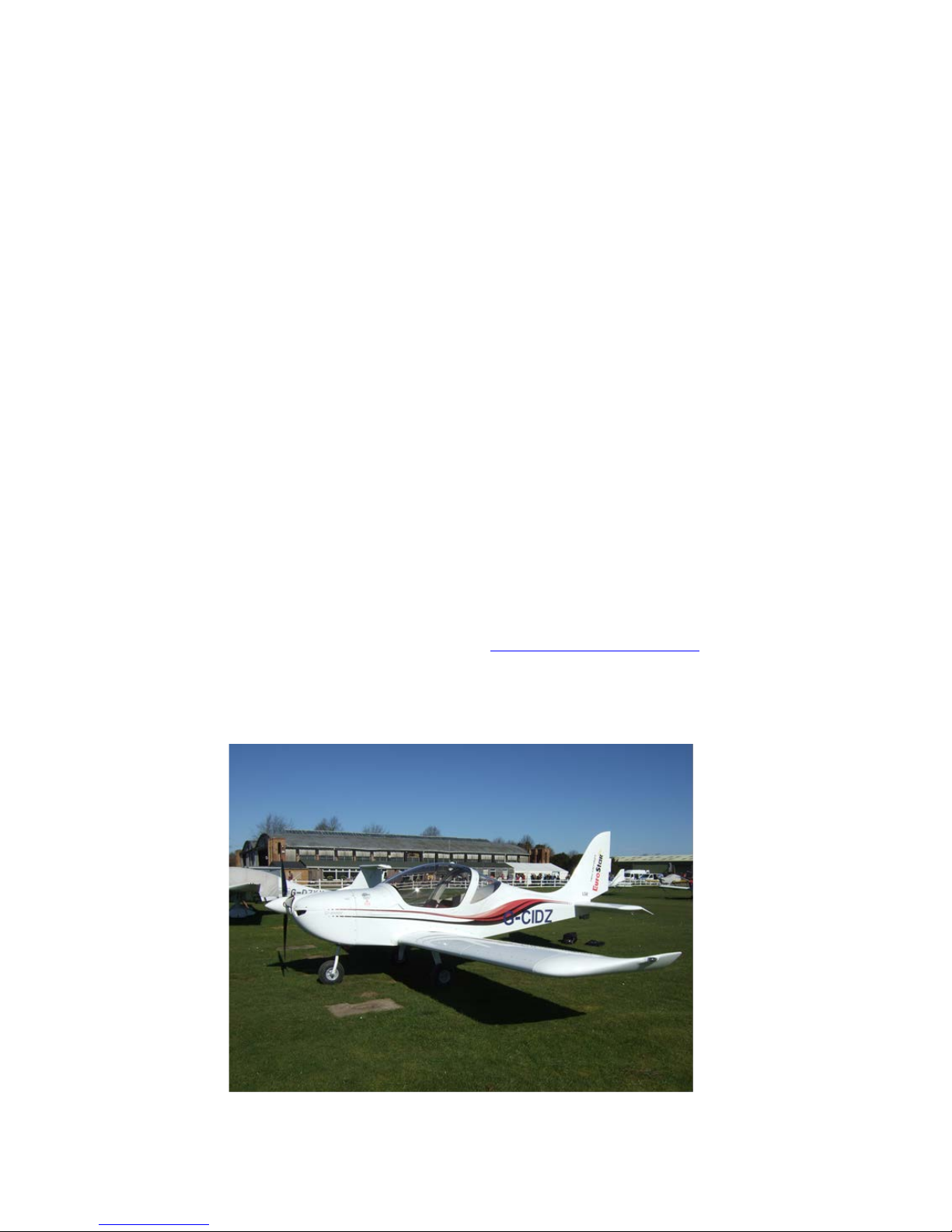
EV-97 EUROSTAR SL
MICROLIGHT
MAINTENANCE MANUAL
GEN/EUR/04
Light Sport Aviation Tel. Office: 01494 524020
Wycombe Air Park, Email: lsa@live.co.uk
Hangar 1 Web: www.lightsportaviation.org.uk
Booker
Marlow
Buckinghamshire
SL6 3DP

EV-97 Eurostar SL Microlight Maintenance Manual GEN/EUR/04 Issue 3 2
Amendment Record
Issue
Details of Change
Date
Authorised
1
First Issue
12/05/14
2 Changes to electrical circuit diagrams (Appendix 5)
15/07/14
Change to trim tab deflection (pages 29 and 42)
15/07/14
3
Change to cockpit instruments (page 9 sect 2.12)
01/09/14

EV-97 Eurostar SL Microlight Maintenance Manual GEN/EUR/04 Issue 3 3
Table of Contents
1. Introduction............................................................................................................................... 5
2. Aircraft Technical Description ................................................................................................... 5
2.1 General .............................................................................................................................. 5
2.2 Dimensions – Drawings...................................................................................................... 5
2.3 Basic dimensions ............................................................................................................... 6
2.4 Weight ................................................................................................................................ 6
2.5 Centre of Gravity ................................................................................................................ 6
2.6 Wing................................................................................................................................... 7
2.7 Horizontal Tail Unit ............................................................................................................. 7
2.8 Vertical Tail Unit ................................................................................................................. 7
2.9 Landing Gear ..................................................................................................................... 7
2.10 Wheels ............................................................................................................................... 7
2.10.1 Wheel Brakes .............................................................................................................. 8
2.11 Tyres .................................................................................................................................. 8
2.12 Cockpit ............................................................................................................................... 9
2.13 Additional Equipment List ................................................................................................... 9
2.14 Control Systems ................................................................................................................. 9
2.15 Flap Control ..................................................................................................................... 10
2.16 Elevator Trim .................................................................................................................... 11
2.17 Power Plant ...................................................................................................................... 11
2.18 Engine Operational Limits ................................................................................................ 13
2.19 Engine Mount ................................................................................................................... 13
2.20 Engine Cowlings .............................................................................................................. 13
2.21 Fuel System ..................................................................................................................... 14
2.22 Cooling System ................................................................................................................ 14
2.23 Cockpit Heating System ................................................................................................... 14
2.24 Ventilation ........................................................................................................................ 15
2.25 Electrical System.............................................................................................................. 15
2.26 Pitot-Static System ........................................................................................................... 15
2.27 Galaxy Balistic Rescue System GRS 6 473 SD B2 .......................................................... 15
2.28 Stall Warner ..................................................................................................................... 16
3. Aircraft Assembly and Disassembly of Major Parts ................................................................. 16
3.1 Wing................................................................................................................................. 16
3.2 Horizontal Tail Unit (HTU) ................................................................................................ 18
3.3 Vertical Tail Unit ............................................................................................................... 18
4. Inspections and Scheduled Maintenance ............................................................................... 18
4.1 Pre-Flight Inspection ........................................................................................................ 18
4.2 Post-flight inspection ........................................................................................................ 19
4.3 Periodic inspections ......................................................................................................... 19
4.3.1 Periodic inspection intervals ...................................................................................... 19
4.3.2 Periodic maintenance and inspection work sheets ..................................................... 19
4.3.3 Periodic Maintenance and Inspections. ..................................................................... 20
5. Maintenance Procedures ........................................................................................................ 27
5.1 Rotax 912 UL engine ....................................................................................................... 27
5.2 Oil .................................................................................................................................... 27
5.3 Oil Draining ...................................................................................................................... 27
5.4 Oil Filter Replacement ...................................................................................................... 27
5.5 Coolant ............................................................................................................................ 27
5.6 Brake System ................................................................................................................... 28
5.6.1 Fluid Type .................................................................................................................. 28
5.6.2 Brake fluid refilling ..................................................................................................... 28
5.6.3 Brake fluid emptying .................................................................................................. 28
5.6.4 Brake Pad Replacement ............................................................................................ 28
5.6.5 Bleeding .................................................................................................................... 29
5.7 Control Surface Deflection Setting ................................................................................... 29
5.7.1 Aileron ....................................................................................................................... 31

EV-97 Eurostar SL Microlight Maintenance Manual GEN/EUR/04 Issue 3 4
5.7.2 Flap ........................................................................................................................... 31
5.7.3 Elevator ..................................................................................................................... 31
5.7.4 Rudder ....................................................................................................................... 32
5.7.5 Trim Tab .................................................................................................................... 32
6. Fueling ................................................................................................................................... 32
6.1 Filling – Precaution ........................................................................................................... 32
6.2 Fuel emptying .................................................................................................................. 33
7. Lubrication .............................................................................................................................. 33
7.1 Engine .............................................................................................................................. 33
7.2 Airframe ........................................................................................................................... 33
7.3 Lubricating Points............................................................................................................. 34
7.4 Access Holes for Lubricating & Inspection ....................................................................... 34
8. Bolt Tightening ....................................................................................................................... 35
9. Rudder ................................................................................................................................... 35
9.1 Rudder Cable Tension Adjustment ................................................................................... 35
9.2 Rudder Pedal Adjustment ................................................................................................ 36
10. Trim Tab Control Cable Tension ............................................................................................. 36
11. Jacking the Aircraft ................................................................................................................. 36
12. Puncture Repair ..................................................................................................................... 36
12.1 Main wheel: ...................................................................................................................... 37
12.2 Nose wheel: ..................................................................................................................... 37
12.3 Puncture Repair – all tyres ............................................................................................... 37
12.4 Tyre pressures (for tyre size 14 x 4 or 400 x 6) ............................................................... 37
13. Small Repairs ......................................................................................................................... 37
14. Care and Cleaning Recommendations ................................................................................... 38
14.1 External Paint ................................................................................................................... 38
14.2 Canopy ............................................................................................................................ 38
14.3 Upholstery ........................................................................................................................ 38
15. Levelling ................................................................................................................................. 38
16. Control Surface Deflections .................................................................................................... 38
17. Permissible Tolerances (Play) ................................................................................................ 39
18. Weighing the Aircraft and Centre of Gravity Calculation ......................................................... 40
18.1 Empty weight determination ............................................................................................. 40
18.2 Operating c.g. range calculation ....................................................................................... 41
Appendix 1 - Levelling Record ...................................................................................................... 42
Appendix 2 - Control Surface Deflection Record ........................................................................... 43
Appendix 3 - Weight & Balance Record ........................................................................................ 44
Appendix 4 - Flight Test Record .................................................................................................... 45
Appendix 5 – Electrical Circuit Diagrams ...................................................................................... 46
Appendix 6 - Additional Equipment List ......................................................................................... 47
EV-97 Eurostar SL Microlight Maintenance Manual GEN/EUR/04 Issue 3 5
1. Introduction
This Maintenance Manual gives recommended procedures for ensuring the continued
airworthiness of the aircraft. Maintenance requirements will depend on aircraft usage and may
need amending accordingly. The operator should always be alert for developing problems and
attentive to ensuring their timely rectification.
2. Aircraft Technical Description
2.1 General
The Eurostar SL airframe is a metal/composite, semi-monocoque construction formed with metal
reinforcements, bulkheads and Duralumin skins. Both pop (blind) rivets and solid ri vets are used
for joints. All Metal parts are primary structures. All composite parts, with the exception of the
undercarriage legs, are non-structural (secondary structures).
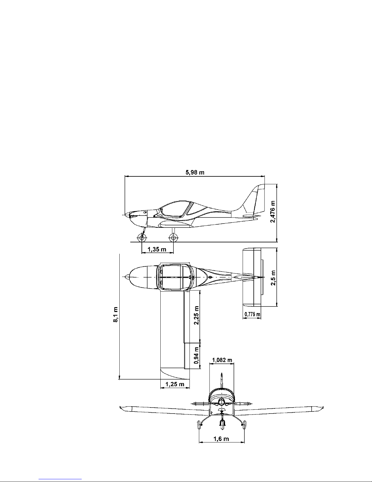
2.2 Dimensions – Drawings

EV-97 Eurostar SL Microlight Maintenance Manual GEN/EUR/04 Issue 3 6
2.3 Basic dimensions
Wing span ............................................... 26.57 ft. 8.1m
Wing area ............................................. 105.92 sq. ft. 9.84m
2
MAC ......................................................... 4.10 ft. 1.25m
Wing loading (MTOW, 1030 lb, 472.5 kg) 9.72 lb./sq. ft. 48 kg/m
2
Aileron area .............................................. 2.26 sq. ft. 0.21m
2
Flap area ............................................... 5.60 sq. ft. 0.52m
2
Fuselage length ...................................... 19.62 ft. 5.98m
Fuselage width ......................................... 3.41 ft. 1.04m
Fuselage height ........................................ 7.68 ft. 2.34m
Horizontal Tail Unit (HTU)
Span ......................................................... 8.20 ft. 2.5m
HTU area ................................................ 20.99 sq. ft. 1.95m
2
Elevator area ............................................ 8.61 sq. ft. 0.8m
2
Vertical Tail Unit (VTU)
Height ....................................................... 4.21 ft. 1.28m
VTU are a ................................................ 10.93 sq. ft. 1.02m
2
Rudder area .............................................. 4.67 sq. ft. 0.43m
2
Landing gear
Wheel tr ack ............................................... 5.25 ft. 1.6m
Wheel base ............................................... 4.42 ft. 1.35m
Main wheel diameter ................................. 14 in 350mm
Nosewheel diameter ................................. 14 in 350mm
2.4 Weight
Empty weight will vary with selection of options and small manufacturing variations. However there
is a maximum limit to the aircraft’s dry empty weight, as shown below.
Empty weight max.(standard equipment) 290.5kg + 0, - 3%
Maximum Take-off weight 472.5kg
Maximum Landing weight 472.5kg
Max. fuel weight, (standard 65 l fuel tank) 47kg
Maximum weight in Baggage Compartment 15kg
NOTE
Actual empty weight is stated on the placard “LOAD LIMITS,“
located on the instrument panel. Empty weight includes 2.9 litres of unusable
fuel.
2.5 Centre of Gravity
Empty weight CG (standard equipment) 18 ±2% Mean Aerodynamic Chord (MAC)
200 – 250mm AoD
Operating CG 20-34% MAC
250 – 410mm AoD
EV-97 Eurostar SL Microlight Maintenance Manual GEN/EUR/04 Issue 3 7
ANGLE REINFORCEMENT
MAIN LEG
MAIN LEG ATTACHMENT
MAIN LEG ATTACHMENT
2.6 Wing
The rectangular wing has a single, aluminium main spar and rear spar to which are attached
ailerons and flaps. All components are riveted. The composite wing tips are attached by rivets.
2.7 Horizontal Tail Unit
The rectangular HTU comprises a stabilizer and elevator with trim tab. It has a sem i-monocoque
construction (i.e. the skins bear part of the load), consisting of Duralumin pressed ribs, spar and
skins. The HTU width of 2.5m permits transport by road without removal.
The stabilizer is attached to the fuselage by two pins at the leading edge and secured with two
screws at the trailing edge.
2.8 Vertical Tail Unit
The trapezoidal VTU comprises fin and rudder. The rudder is attached to the fin by t wo hinges
consisting of spherical joints bolted into the fin’s trailing edge spar.
A composite fairing is fitted immediately forward of the fin, blending its surface with that of the
fuselage top.
Neither composite tip, nor forward fairing takes significant structural loads.
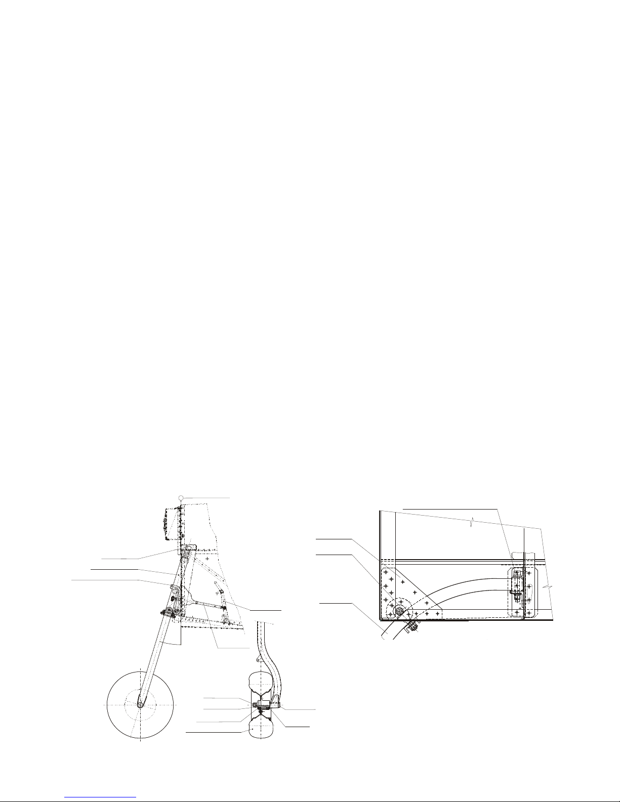
2.9 Landing Gear
The fixed gear consists of:
• a steerable nose wheel on a leg sprung on a rubber rope suspension. The nose leg is
constructed from steel tube and mount ed on the firewall on two bearings. The nose wheel
is steered by two push rods connected to the rudder pedals.
• hydraulically brak ed main wheels and composite spring legs attached to the fuselage cross
member under the seats. These legs are designed to deflect to reduce landing impact.
The leg’s attachment to the fuselage is shown below:
2.10 Wheels
1
7
°
NOSE WHEEL
CONTROL ROD
FOOT PEDAL
SUSPENSION STOP
NOSE WHEEL LEG
RUBBER ROPE SUSPENSION
FUSELAGE FRAME
WHEEL AXLE
WASHER
E 54-04 21
NUT 765 155
WASHER 765 478
NOSE WHEEL ASSEMBLY
COTTER PIN 4x40
ČSN 02 1781.04
1
EV-97 Eurostar SL Microlight Maintenance Manual GEN/EUR/04 Issue 3 8
Each wheel consists of a two-part cast alloy r im with tyre and inner tube. The main wheels are
mounted on an axle secured to the composite leg by 4 bolts. Cross sections of the main and nose
wheels and their axles are shown below:
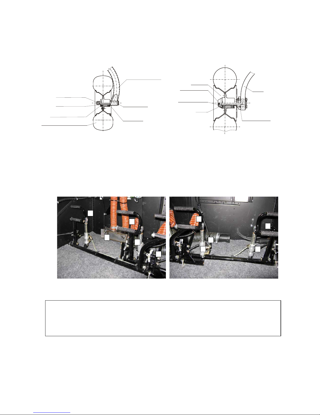
2.10.1 Wheel Brakes
Both wheels on the main landing gear are equipped with hydraulic disc brakes. The brake
system consists of the brake pedals (pilot standard, co-pilot as an option), hydraulic brake
master cylinders, plastic hoses, brake caliper with the hydraulic brake cylinder, brake pads and
the brake disc which is bolted onto the inner part of the rim.
The brakes on both wheels are controlled independently by toe brake pedals mounted on the
pilot’s and the co-pilot’s rudder pedals.
Fig. The brake control with toe brake pedals
1 – ruder pedals, 2 – brake cylinder, 3 – nose wheel steering rod
2.11 Tyres
SAVA 14 x 4 (standard), all three wheels.
NOSE WHEEL LEG
WHEEL AXLE
WASHER
E 54-04 21
NUT 765 155
WASHER 765 478
NOSE WHEEL ASSEMBLY
COTTER PIN 4x40
ČSN 02 1781.04
SCREW 4x40 ČSN 02 1781.04
NUT M16x1.5 ČSN 02 1412.24
WASHER
WHEEL WITH BRAKE
SCREW 5x10 ČSN 02 2150.01
MAIN LEG
2 3 2 1 1
3 1 2 2 1
WARNING
When adjusting the rudder pedals, if the plungers are not fully engaged in one of the
three holes in the plate, the pedal may rotate backwards and prevent rudder movement.
See Brake Pedal Adjustment section 9.2
EV-97 Eurostar SL Microlight Maintenance Manual GEN/EUR/04 Issue 3 9
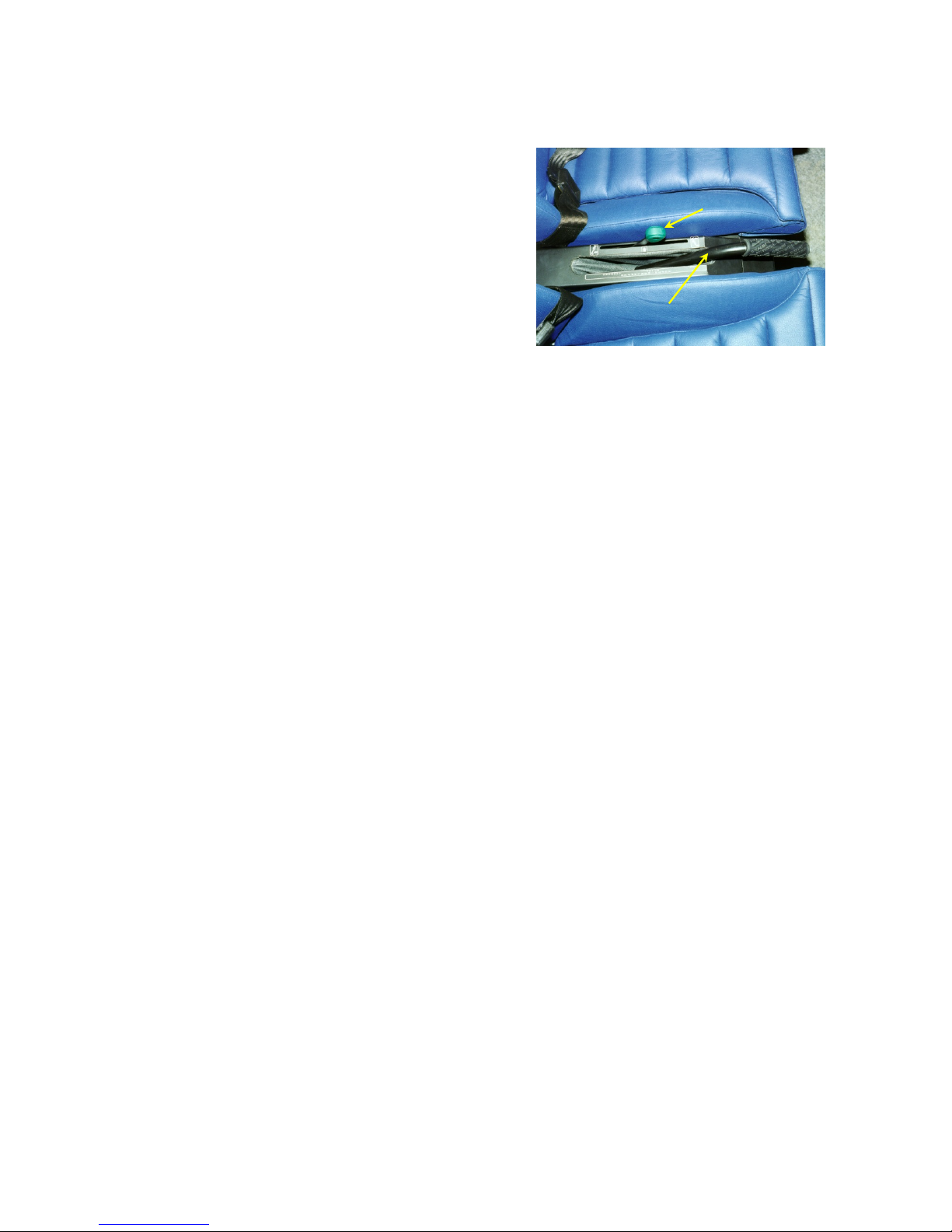
2.12 Cockpit
Two side by side seats have between them the levers
for elevator trim and flaps. Floor covering is lightweight
removable carpet and interior trim panels can be
removed for cleaning or access.
The canopy has two parts: a fixed part to the rear and a
forward-opening part at the front. Acrylic (Perspex)
transparencies are used in both parts. Two gas struts
aid opening and a lock is fitted to the top rear of the
opening section. The lock mechanism carries a microswitch operating a lamp on the panel showing the pilot
when the canopy is properly locked.
The following electronic or analogue instruments are fitted to the panel:
1. Airspeed Indicator (ASI)
2. Altimeter
3. Compass
4. Vertical Speed Indicator(VSI)
5. Tachometer
6. Cylinder Head Temperature (CHT) gauge
7. Oil temperature gauge
8. Oil pressure gauge
9. Fuel pressure gauge
10. Fuel contents gauge
11. Engine hours indicator.
2.13 Additional Equipment List
See additional equipment list Appendix 6 if applicable
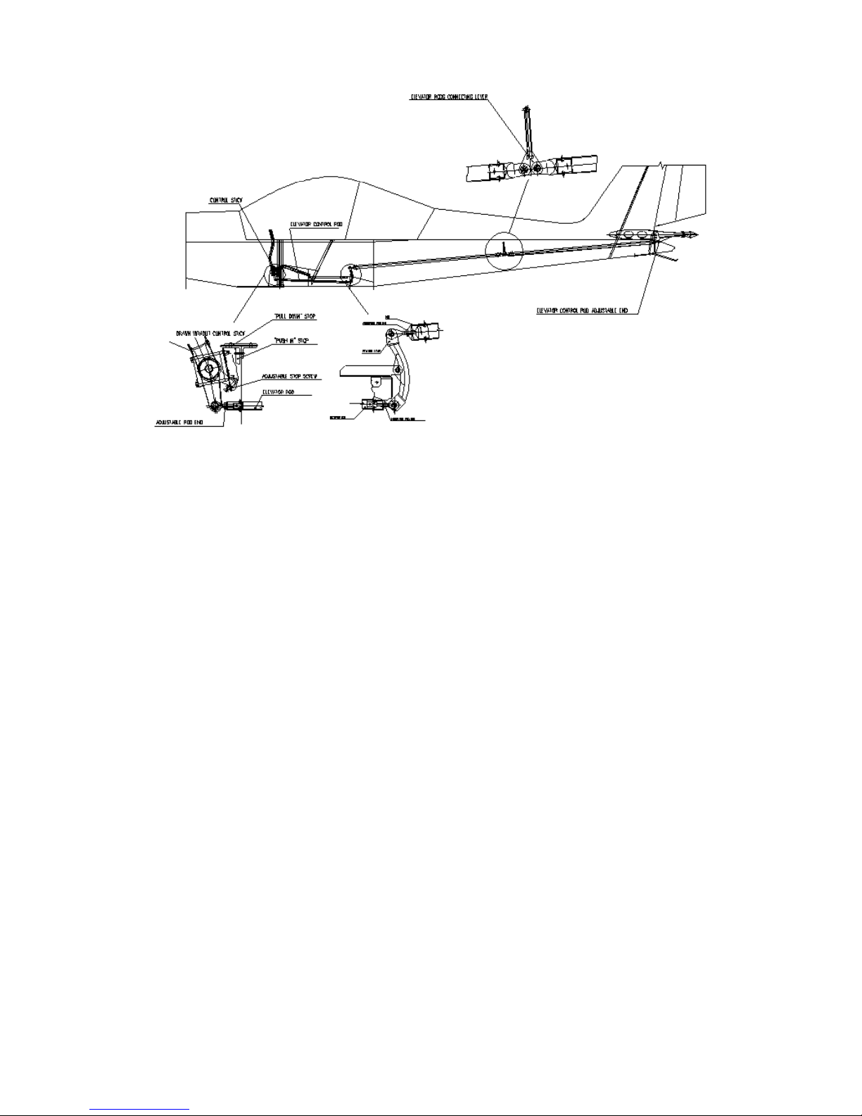
2.14 Control Systems
Longitudinal Control (Pitch) – The elevator is controlled by a system of push rods. Movement of the
control stick is passed into a torque tube running along the front of the seats. An arm is attached
to this tube near its centre which connects a push rod to a relay arm mounted beneath the
baggage bay. From here, a second push rod connects to an intermediate relay arm mount half
way along the fuselage rear, and from this point a thir d push rod connects to t he elevator horn; the
system is shown below.
See additional equipment list Appendix 5 if applicable
Elevator trim
Flap lever
EV-97 Eurostar SL Microlight Maintenance Manual GEN/EUR/04 Issue 3 10
Lateral Control (Roll) – ailerons are also controlled by push rods. Lateral movement of either
control stick is transferred, via a short rod in the cockpit, to a long push rod in the wing,
immediately in front of the main spar. A bell crank, connected to the end of the long push rod,
converts span wise movement to a chord wise one, and a third pushrod terminates on the aileron
horn to deflect it up or down. The short chord wise push rods can be adjusted to achieve the
correct aileron deflections. The control stick base incorporates a stop.
Directional Control (Yaw) – cables, att ached to arms at the end of the rudder pedals’ torq ue tubes,
are guided along the sides of the fuselage to the rudder horn. Stops, in the form of swages
crimped on to the cable, are located at points where the cable passes through fuselage side
stiffeners; adjusters are installed at these points.
Push rods attached to the inboard rudder pedals connect to either side of the steering yoke of the
front wheel, permitting direct steering via the rudder pedals. Since this system and the rudder
cables form a closed loop, rudder cable tension can be adjusted by changing the lengths of the
steering push rods, using the rod ends screwed into their ends.
Toe Brakes - The brakes are controlled independently by hydraulic toe brake pedals mounted on
the pilot’s and the co-pilot’s (optional) rudder pedals.
2.15 Flap Control
Wing flaps are controlled by a gated lever located between the seats; the lever is released by
pressing the lock button on the lever’s end.
Push – pull movement of the lever is translated into a longitudinal movement of a push rod by a
quadrant mounted at its base. The other end of t he pus h r od connec t s t o the arm of a torque tube
passing across the fuselage and exiting the wall at each side adjacent to the flap end. An ar m on
each end of the torque tube engages in slots in the flap end t o deploy or retract the flaps. Where
the arm engages in the flap end, an eccentric is provided to permit fine adjustment and balance of
the flaps’ deflections. The system is shown below:

EV-97 Eurostar SL Microlight Maintenance Manual GEN/EUR/04 Issue 3 11
2.16 Elevator Trim
The elevator’s trim tab is moved by a control lever located between the seats. Movement of the
lever is passed to a pair of Bowden cables which run along the fuselage floor to the elevator trim
tab.
2.17 Power Plant
An 80hp Rotax 912 UL engine drives a 3 blade Woodcomp 170/3/R or a Kievprop 237/1700
propeller via a 2.27:1 reduction drive gearbox. The Rotax 912UL is a 4-stroke, 4 cylinder,
horizontally opposed, spark ignition engine and has one central camshaft operating push-rods for
the overhead valves. Cylinders are cooled by a combination of oil and ram air; cylinder heads are
liquid cooled.
The engine has a dry sump with pumped lubrication and a dual breaker less capacitor discharge
ignition system which does not require battery power for its operation. The engine is fitted with an
electric starter, alternator and mechanical fuel pump.
Full technical details of the engine can be found in the Rotax Operator’s Manual. Engine
performance and limitations are summarized below. It should be noted that the aircraft
manufacturer places certain limits on engine operation, lower than those given by the engine
manufacturer:
EV-97 Eurostar SL Microlight Maintenance Manual GEN/EUR/04 Issue 3 12
Full details of the propeller can be found in the propeller manufacturer’s Operator’s Manual.
Engine Model: ROTAX 912 UL
Engine Manufacturer: BRP – Powertrain GMBH
Power
Max Take-off: 59.6 kW / 80 hp at 5800 rpm, max.5 minutes
Max. Continuous: 56 kW / 75 hp at 5200 rpm
Cruising: 53 kW / 71 hp at 4800 rpm
Engine
speed
Max. Take-off: 5800 rpm, max. 5 min.
Max. Continuous: 4800 rpm
Cruising: 4600 rpm
Idling: ~1400 rpm
Cylinder head
temp.
Minimum 60 °C 140 °F
Maximum 120 °C (1) 248 °F
Coolant temp.
Maximum 115 ºC (1) & (2) 239 °F
Oil temp.
Minimum 50 °C 122 °F
Maximum 140 °C 284 °F
Optimum 90 – 110 °C 194 - 230°F
Oil pressure
Maximum 7,0 bar
Minimum 1,5 bar
Optimum 1,5-4,0 bar
Fuel: Premium or super unleaded automobile fuel to EN228, minimum RON 90.
AVGAS UL 91 Certified to ASTM D7547
AVGAS 100LL. The higher lead content in AVGAS can result in wear of valve
seats and increased combustion chamber deposits.
Use AVGAS only if other fuels are not available.
For other suitable fuel types, refer to the engine Operator’s Manual.
Fuel Pressure min. 0.15 bar, max. 0.4 bar
Oil: Automotive engine oil of registered brand with gear additives, but not aircraft oil
(refer to engine Operator´s Manual).
API classification SF or SG. (2)
Propeller Woodcomp 170/3/R or Kievprop 273/1700
Type 3 Blade ground adjustable pitch, composite
Propeller Pitch 28º at 350 mm radius, however see note 1.
(1) With 50/50 Ethylene Glycol/water coolant mix.
(2) Service Bulletin SB/EUR/006 Issue 1 is complied with.
WARNING
The Rotax 912 UL has not been certified as an aircraft engine and its failure may occur at
any time. The pilot is fully responsible for consequences of such a failure. Never fly over
an area on to which you cannot safely land in the event of an engine failure.
Note 1: propeller pitch to be set to achieve 4600rpm static at full throttle.

EV-97 Eurostar SL Microlight Maintenance Manual GEN/EUR/04 Issue 3 13
2.18 Engine Operational Limits
Parameter
Minimum
Limit
(red line)
Normal
Operating
(green arc)
Caution
Range
(yellow arc)
Maximum
Range
(red line)
Engine speed
[RPM]
1400 1400-4800 4800-5800 5800
Cylinder Head
Temp.
(CHT)
R 912
UL
(80 hp)
- -
-
-
150 °C
(Evans
coolant)
120 °C
(glycol coolant)
Exhaust Gas
Temp. (EGT)
- - - 880 °C
1616 ° F
Oil
Temp.
R 912 UL
(80 hp)
50 °C
122 °F
90-110 °C
194-230 °F
50-90 °C
122-194 °F
110-140 °C
230-284 °F
140 °C
284 °F
Oil
Pressure
0.8 bar
12 psi
2 - 5 bar
29 – 73 psi
0.8 - 2 bar
12 - 29 psi
5 – 7 bar
73 – 102 psi
7.0 bar
102 psi
cold engine
starting
2.19 Engine Mount
The engine mount is welded from chrome-molybdenum tube and is attached to the firewall by 4
bolts. The assembly incorporates 4 anti-vibration mounts (Silent blocs).
2.20 Engine Cowlings
Two composite cowlings, upper and lower, cover the power plant. Both cowlings are coated
internally with fireproof paint. The upper cowling is connected to the lower cowling by quarter turn
fasteners and is easily removed for pre-flight inspections. Removal of t he lower cowling requires
removal of the screws supporting the radiator to the front of the cowling, then removal of the
screws supporting the lower cowling’s rear edge.
Engine cowlings disassembly and assembly
• The upper cowling: The disassembly and assembly are both easy by releasing
the quick-closing locks (or screws). The upper cowling is usually removed during
engine pre-flight inspection to check the engine compartment, operating fluids
quantity (oil, coolant) and to check the engine installation.
• The lower cowling: To remove it, un-screw the attachment screws connecting the
cooler to the cowling face side, then remove two air hoses (unsc r ew sleeves) and
then un-screw the attachment screws connecting the cowling to the firewall
outside edge.
It is highly recommended to protect the removed cowlings so as to prevent them
from inadvertent damage.
The cowling assembly is the reverse of disassembly.
EV-97 Eurostar SL Microlight Maintenance Manual GEN/EUR/04 Issue 3 14
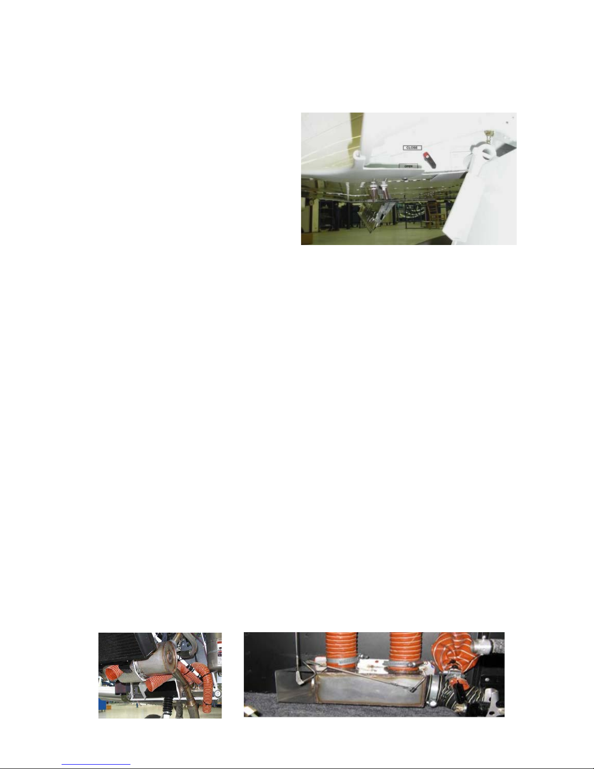
2.21 Fuel System
A 65 litres fuel tank is installed behind the seat and feeds fuel to a tap located inside the cockpit on
the port side, below the instrument panel. Fuel then passes through a filter to the engine fuel
pump and the carburetors.
The fuel system incorporates a sump and drain
valve to collect water and other contaminants in
the fuel. The drain outlet is located under the
fuselage, near the starboard flap root, and is
accessible when the flaps are fully extended.
(See photo on the right). The tank’s vent also
terminates adjacent to this drain outlet.
A filler cap is installed on the starboard side of
the fuselage.
Fuel quantity is indicated on the panel by a gauge operating from a float sender inside the tank.
The aircraft must be on level ground. It is highly recommended to have accurate knowledge of fuel
load before each flight. Timing fuel burn is also recommended during each flight.
2.22 Cooling System
Two forms of cooling keep engine temperatures under control: cylinder heads are liquid cooled;
cylinders are ram air cooled. A coolant radiator is mounted in the front of the lower engine cowling;
coolant is forced through the radiator to the cylinder heads by a water pump driven from the
crankshaft. Coolant then passes from the top of the cylinder heads to an expansion tank mounted
on top of the engine. This tank allows the coolant to expand and is fitted with a pressure relief cap
and return valve system. Excess coolant passes through the cap into a small plastic overflow
bottle mounted on the firewall.
The coolant level in the expansion tank should be checked before the first flight of the day and
should reach the bottom of t he filler neck. Normal coolant level in the overflow bottle is leve l is ½
to 2/3 up the tank (0.2 litres); minimum level is 25mm from the bottom.
2.23 Cockpit Heating System
One intake air hose routes outside air to the heat exchanger (a jacket around the exhaust), where
the air is heated. It is then led through a valve on the firewall to the mixing chamber on the cockpit
floor. When the valve is closed, the air is exhausted via an outlet air hose exiting under the
fuselage. A second hose feeds outside air directly through the valve on the firewall to the mixing
chamber on the cockpit floor. It is recommended to fit a carbon monoxide detector
Hot air and cold air valves are operated by a Bowden cable running to small control knobs on the
panel.
Demisting/defrosting of the windshield is per formed by hot air being fed from the m ixing chamber
on the firewall to the internal space of the canopy fram e molding and then through a row of holes
along the bottom edge of the tinted plastic canopy.

EV-97 Eurostar SL Microlight Maintenance Manual GEN/EUR/04 Issue 3 15
2.24 Ventilation
2 eyeball vents mounted
at either side of the
canopy frame provide
fresh outside air. The
vents are connected to
NACA scoops on the
canopy. T urning the rim
adjusts air volume.
2.25 Electrical Syst em
The electrical system uses a single wire supply and chassis (negative) return for all equipment
except avionics units which have their own negative wire returns.
Power for all services except engine ignition is provided by a LiFePO4 (Lithium ion Iron Phosphate)
battery mounted on the firewall and charged via the engine’s alternator and rectifier-regulator. The
battery has its own integrated cell protection and balancing circuits.
All circuits except the starter motor are protected by individual circuit breakers mounted on the right
hand side of the instrument panel. The main battery supply carries a 30A circuit bre aker. Circuit
diagrams for each of the systems are given in Appendix 5.
2.26 Pitot-Static System
The pitot static tube, located under the port wing near the aileron root, provides both dynamic and
static pressures to the instruments via flexible plastic hoses.
Moisture and dirt collection reservoirs are installed inside the cockpit, on the left sidewall in front of
the pilot’s seat.
2.27 Galaxy Ballistic Rescue System GRS 6 473 SD B2
The rocket engine and parachut e is situated under the front scuttle and is designed to f ir e thr oug h
a break away panel. The parachute is attached at 3 points on the fuselage, the first two being the
port and starboard firewall cross-member, the third point can be found on the port side behind the
pilot’s seat. The r ed activation handle is easily visible on the lower edge of the instrument panel
next to the throttle.
IMPORTANT
Before working on the aircraft, ensure that the safety locking pin is inserted in the
parachute deployment handle on the panel. If working on or near the parachute itself,
ensure that the transit safety pin is inserted.
Refer to the parachute manufacturer’s maintenance manual for details of maintenance
required.
WARNING
Avoid blowing into the pitot-static system with the collection reservoir covers on - this
may cause damage to the instruments.
WARNING
The battery will be damaged if allowed to completely discharge or if it is jump
started. Only use the recommended charger. See battery manufacturer’s
maintenance manual.
 Loading...