

Page 1
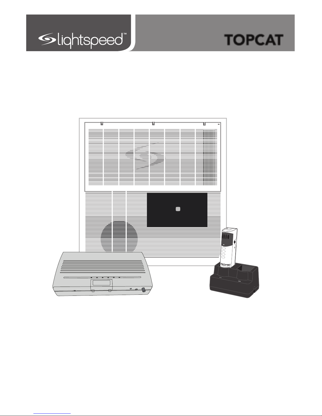
User Manual
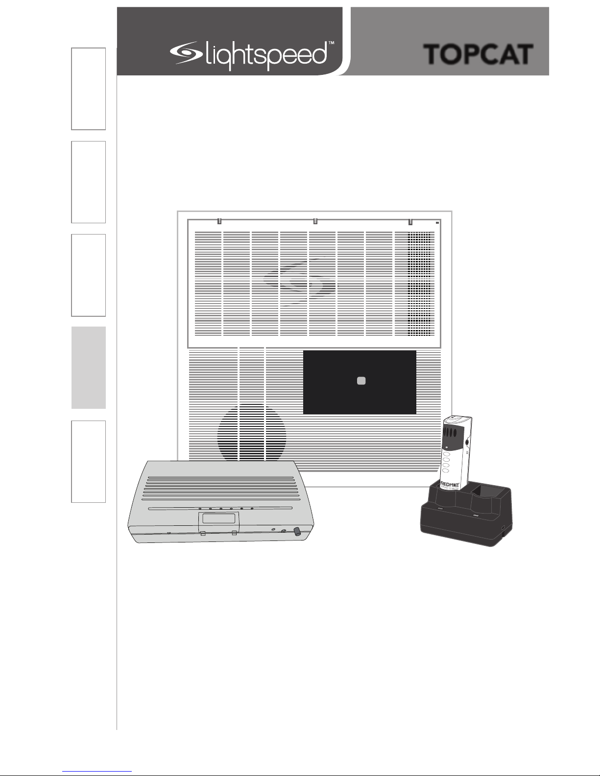
Classroom Audio System
TOPCAT
Page 2

TABLE OF CONTENTS
SECTION 1: 4 Important Safety Instructions
Overview 6 System Components and Unpacking
7 Optional Components
SECTION 2: 9 Installation Planning
Installation 10 Step 1. Select Mounting Location
11 Step 2. Installing the TOPCAT into the Ceiling
Grid
12 Step 3. Securing the TOPCAT
13 Step 4. Installing and Wiring Electrical Power
14 Alternate Power
15 Step 5. Location of the Media Connector
16 Step 6. Connecting the Power Supply
17 Step 7. Audio Integration
18 Step 8. Volume Adjustment for the Media
Connector
19 Step 9. TOPCAT and Media Connector
Registration
20 Step 10. Setup and Operation of the
REDMIKE VC and TOPCAT
21 Tips to Obtain Optimum Audio Performance
22 Step 11. Charging the REDMIKE VC
23 Side Panel Controls and Connections
24 Media Connector Front Panel Controls
25 Media Connector Rear Panel Controls
26 REDMIKE VC Controls and Connections
27 Cradle Charger Controls and Connections
SECTION 3: 28 REDMIKE Share: Controls and Connections
Optional 29 Charging
Accessories 30 Initial Set-Up
30 Optional Pagefirst Interface
31 Using the REDMIKE VC to Amplify External
Audio Equipment
32 Output to Assistive Listening Device (ALD)
33 Optional iR Media Sensor/Receiver (ISR)
Installation
34 IR Sensor/Receiver Installation
39 Remove and Replace Amplifier Module
Page 3

TABLE OF CONTENTS CONT’D
SECTION 4:
42 Troubleshooting Guide
Troubleshooting
SECTION 5: 43 Warranty, Safety & Specifications
Warranty &
Specifications
44 Safety Warnings and Certifications
45 System Specifications
SECTION 6: 50 Important Safety Instructions
Installer’s Manual
Page 4

IMPORTANT SAFETY INSTRUCTIONS
1. Read these instructions.
2. Keep these instructions.
3. Heed all warnings.
4. Follow all instructions.
5. Do not use the apparatus near
water.
6. Clean only with dry cloth.
7. Do not block any ventilation
openings. Install in accordance
with the manufacturer’s
instructions.
8. Do not install near any heat
sources such as radiators,
heat registers, stoves, or
other apparatus (including
amplifiers) that produce heat.
9. Do not defeat the safety
purpose of the polarized
or grounding-type plug.
A polarized plug has two
blades with one wider than
the other. A grounding- type
plug has two blades and a
third grounding prong. The
wide blade or the third prong
is provided for your safety. If
the provided plug does not
fit into your outlet, consult an
electrician for replacement of
the obsolete outlet.
10. Protect the power cord
from being walked on or
pinched particularly at plugs,
convenience receptacles, and
the point where they exit from
the apparatus.
11. Only use attachments/
accessories specified by the
manufacturer.
12. Use only with a cart, stand,
tripod, bracket or table
specified by the manufacturer,
or sold with the apparatus.
When a cart is used, use
caution when moving the cart/
apparatus combination to
avoid injury from tip-over.
13. Unplug this apparatus during
lightning storms or when
unused for long periods of
time.
14. Refer all servicing to qualified
service personnel. Servicing is
required when the apparatus
has been damaged in any way,
such as power-supply cord or
plug is damaged, liquid has
been spilled or objects have
fallen into the apparatus, the
apparatus has been exposed
to rain or moisture, does not
operate normally, or has been
dropped.
15. When the mains plug or
appliance coupler used as
the disconnect device, it shall
remain readily operable.
16. Please keep the unit in a good
ventilation environment.
4
Page 5

IMPORTANT SAFETY INSTRUCTIONS CONT’D
5
To avoid potential equipment damage and/or serious injury, READ AND
FOLLOW all safety precautions when installing the TOPCAT. WARNINGS are
coated throughout the procedural steps in this guide, and are repeated below
for emphasis.
• USE A CERTIFIED ELECTRICIAN FOR POWER CONNECTIONS. The
TOPCAT system uses standard 100 – 240VAC power. Obtain the services of
a certified electrician when supplying and connecting power to the Ceiling
Enclosure. BE SURE electrical installation complies with local building
codes. Improperly installing and/or connecting power to the system may
result in EQUIPMENT DAMAGE, serious INJURY and/or DEATH.
• DO NOT INSTALL ALONE. The Ceiling Enclosure weighs approximately 20
lbs, and requires at least two people to install. DO NOT install alone.
• USE SUITABLE LADDERS. use proper ladders or support platforms when
installing the TOPCAT Enclosure. DO NOT stand on chairs, tables, or other
unsuitable surfaces.
• SUPPORT THE CEILING ENCLOSURE PROPERLY. DO NOT allow the
full weight of the Ceiling Enclosure to rest on the tile grid of the ceiling.
The Ceiling Enclosure is designed to be suspended at TWO POINTS by
suspension wires (secured to rafters or other suitable mounting points) and
to rest LIGHTLY on the tile grid.
Page 6
6
1. Overview 2. Installation
3. Optional
Accessories
4. Troubleshooting
5. Warranty, Safety
& Specifications
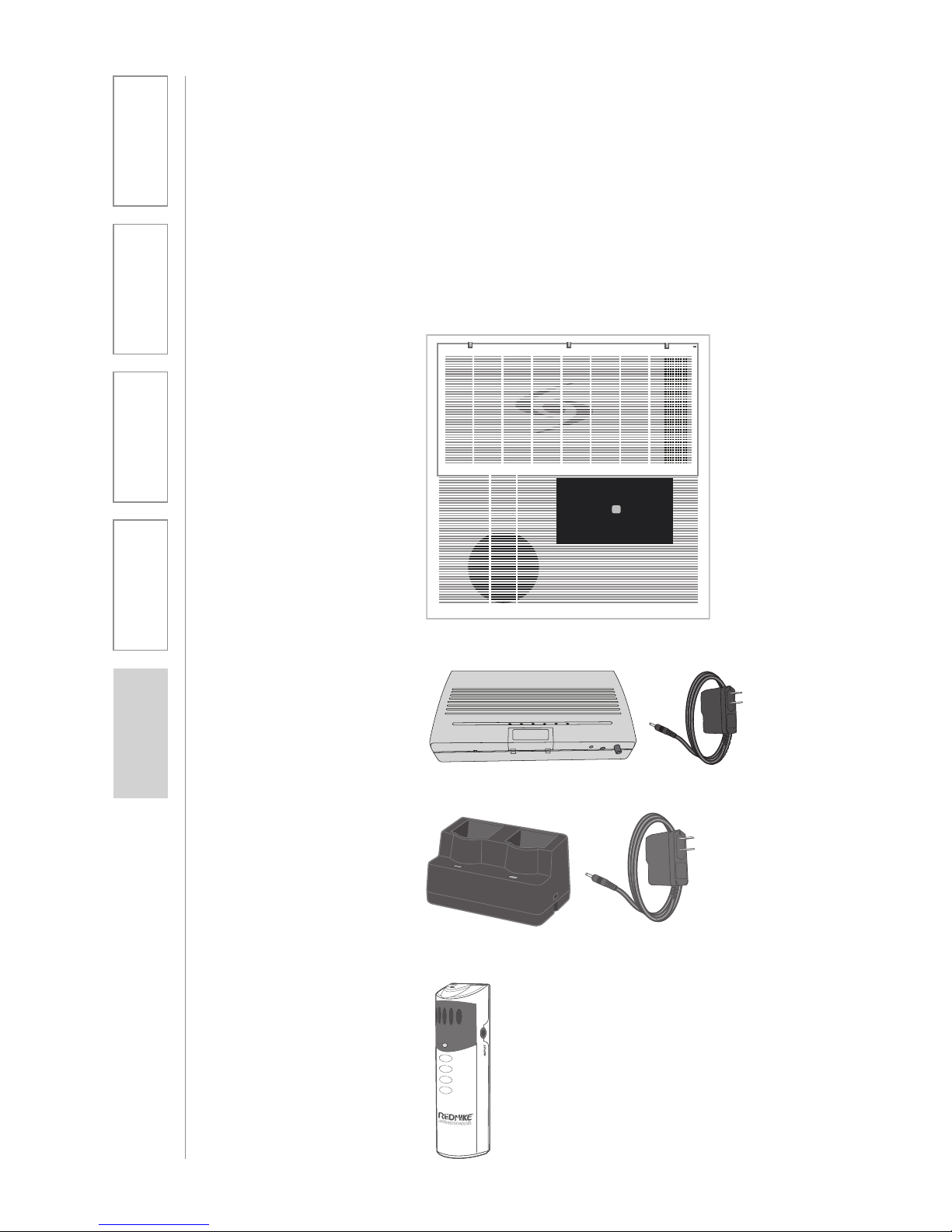
SYSTEM COMPONENTS AND UNPACKING
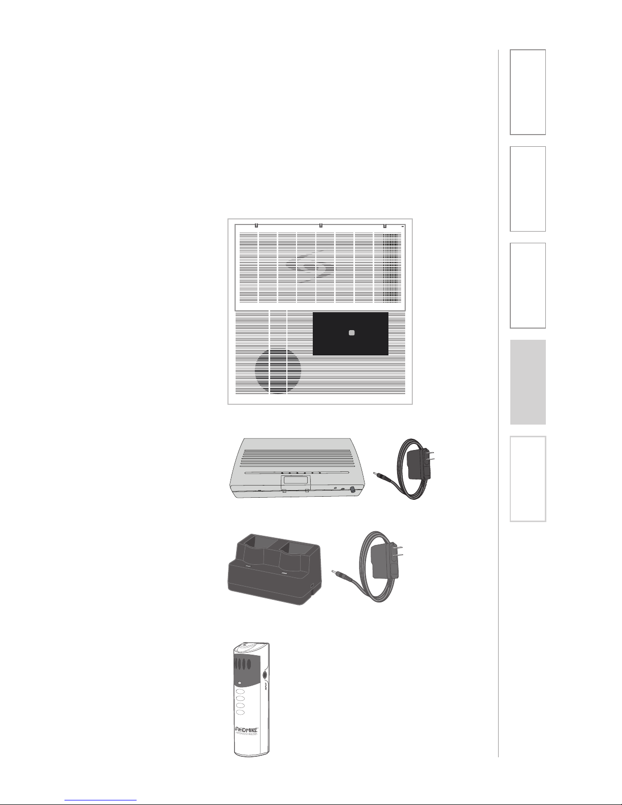
The standard configuration of the TOPCAT® will contain:
Charging Cradle and
Power Supply
REDMIKE® VC
Volume Control
Microphone
TOPCAT Module
Media Connector
Module
SECTION 1:
OVERVIEW
Page 7
7
1. Overview 2. Installation
3. Optional
Accessories
4. Troubleshooting
5. Warranty, Safety
& Specifications
SYSTEM COMPONENTS AND UNPACKING
CONT’D
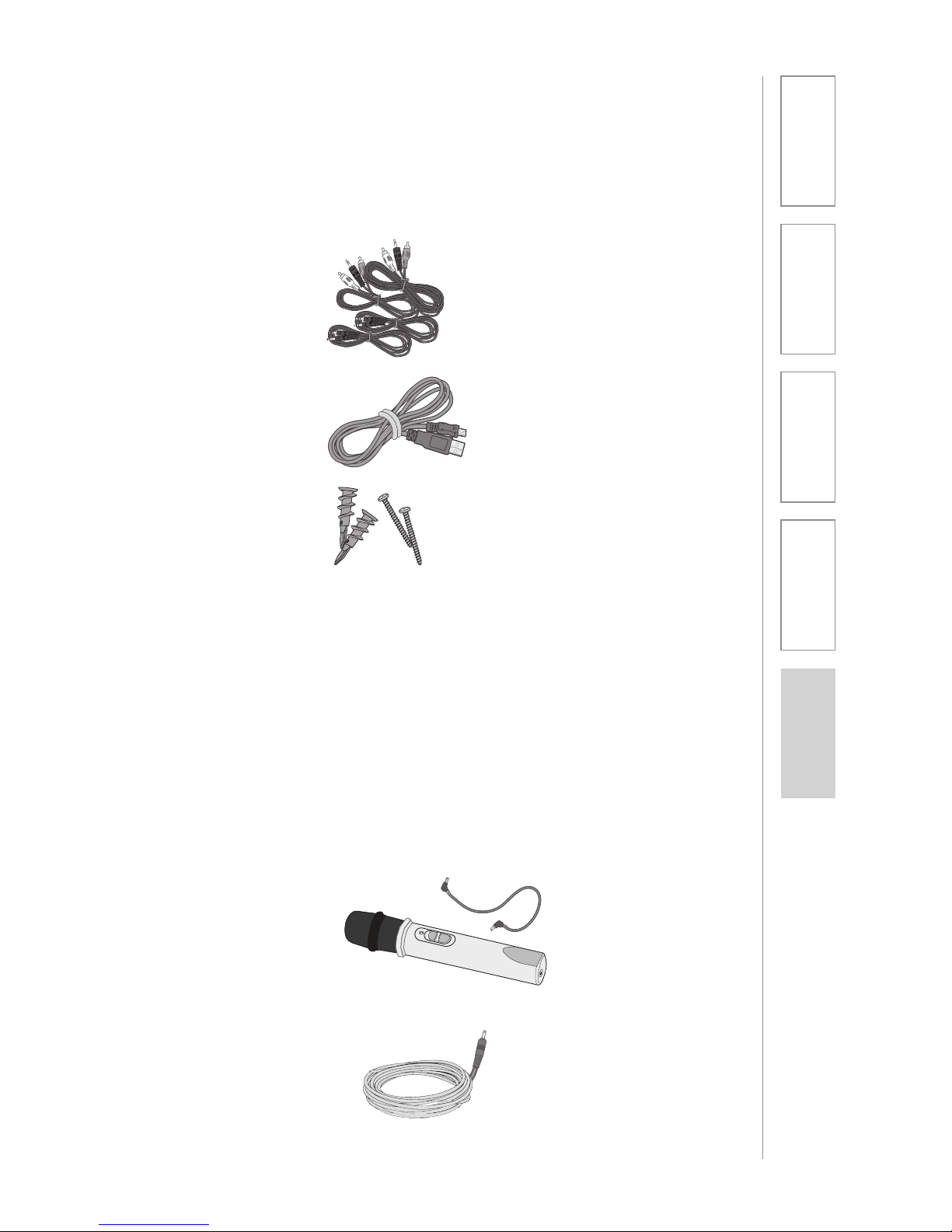
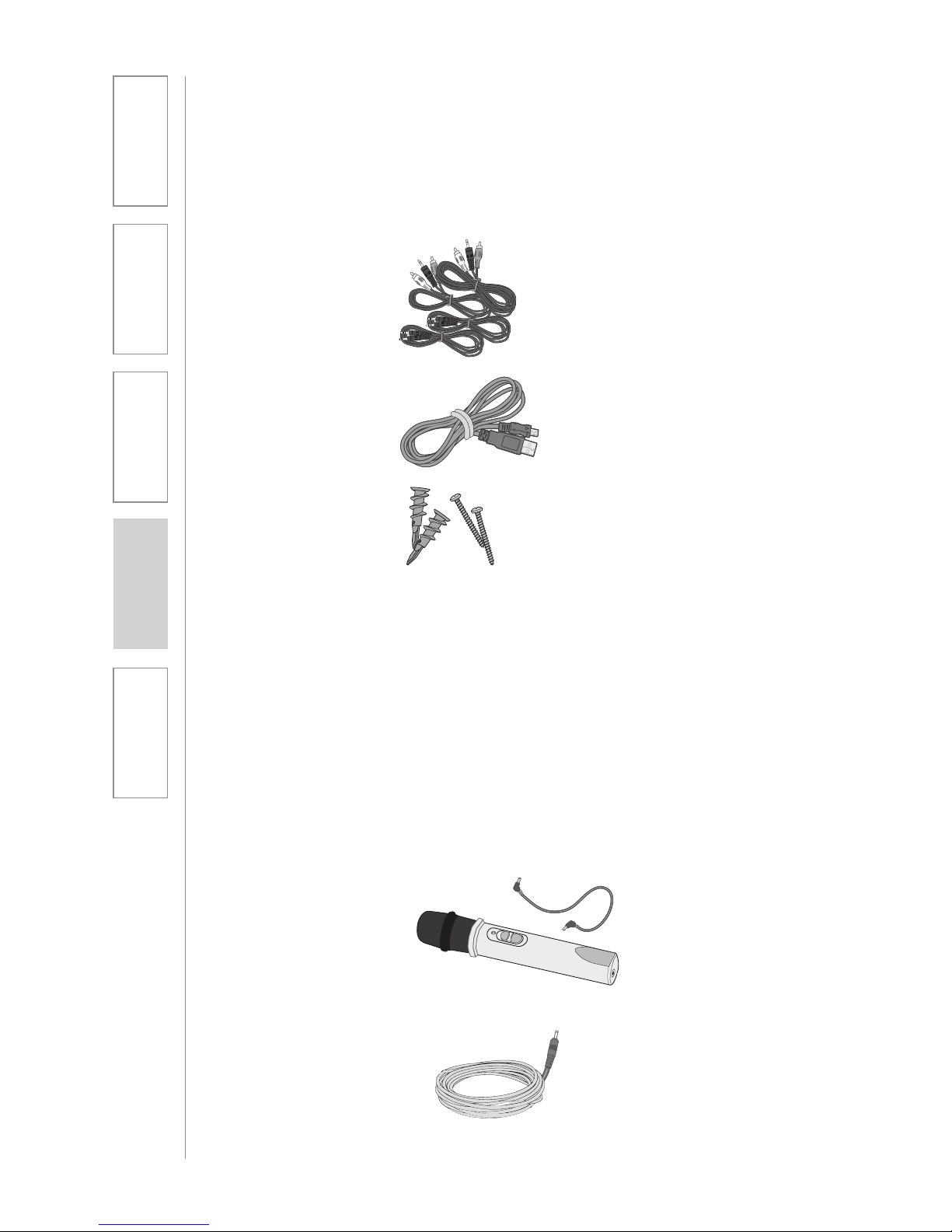
Audio Cable Kit
USB Cable
Screws and Anchors
for optional wall
mounting
OPTIONAL COMPONENTS
Optional equipment which may be part of your TOPCAT system:
REDMIKE® Share
Handheld Mic &
Charger Cable
DC Cable
Page 8

8
1. Overview 2. Installation
3. Optional
Accessories
4. Troubleshooting
5. Warranty, Safety
& Specifications
Standard Accessories
TRX-TC TOPCAT all-in-one ceiling mount system
PS-24V-2.5 24V/2.5A power supply for TOPCAT
RMV REDMIKE VC microphone with battery
BA-NH2A27 AA NiMH rechargeable sensing battery for REDMIKE
AC-RMLC2 REDMIKE lavaliere cord
BC-RMCC REDMIKE cradle charger
PS-5V-1.0 5V/1.0A power supply
TRX-MC Transmitter-Receiver Media Connector Module
CA-USBAM USB cable (type A-MINI-B)
CA-MSC3535 Patch cables 3.5mm to 3.5mm short length
CA-AD-RCA2-35 Dual RCA jack – 3.5mm stereo plug adapter
Optional Components
RMS REDMIKE Share handheld microphone w/battery pack
MC-TK250LTM Noise-canceling headset microphone
AC-TCC7 Charging cable for LT-71 and REDMIKE Share
microphones
CA-RCA6 6’ dual RCA audio cable
CA-RCA24 24’ dual RCA audio cable
CA-MMC2535 Audio patch cable (2.5 mm mono to 3.5 mm mono)
BA-NH2APK AA Rechargeable battery (REDMIKE Share)
DCPEX-NA 50’ plenum rated DC Power cable kit
SYSTEM COMPONENTS
Equipment which may be part of your TOPCAT:
Page 9
9
1. Overview 2. Installation
3. Optional
Accessories
4. Troubleshooting
5. Warranty, Safety
& Specifications
INSTALLATION PLANNING
SECTION 2:
INSTALLATION
Before beginning installation, make sure you have the necessary tools
and materials on hand and that pre-installation site preparation has been
accomplished.
TOOLS & MATERIALS
In addition to the contents of the
TOPCAT system, you will need the
following tools & materials:
• Flat Blade screwdriver (small)
• Pliers
• Wire cutters
• Drill
• Utility Knife
SITE PREPARATIONS
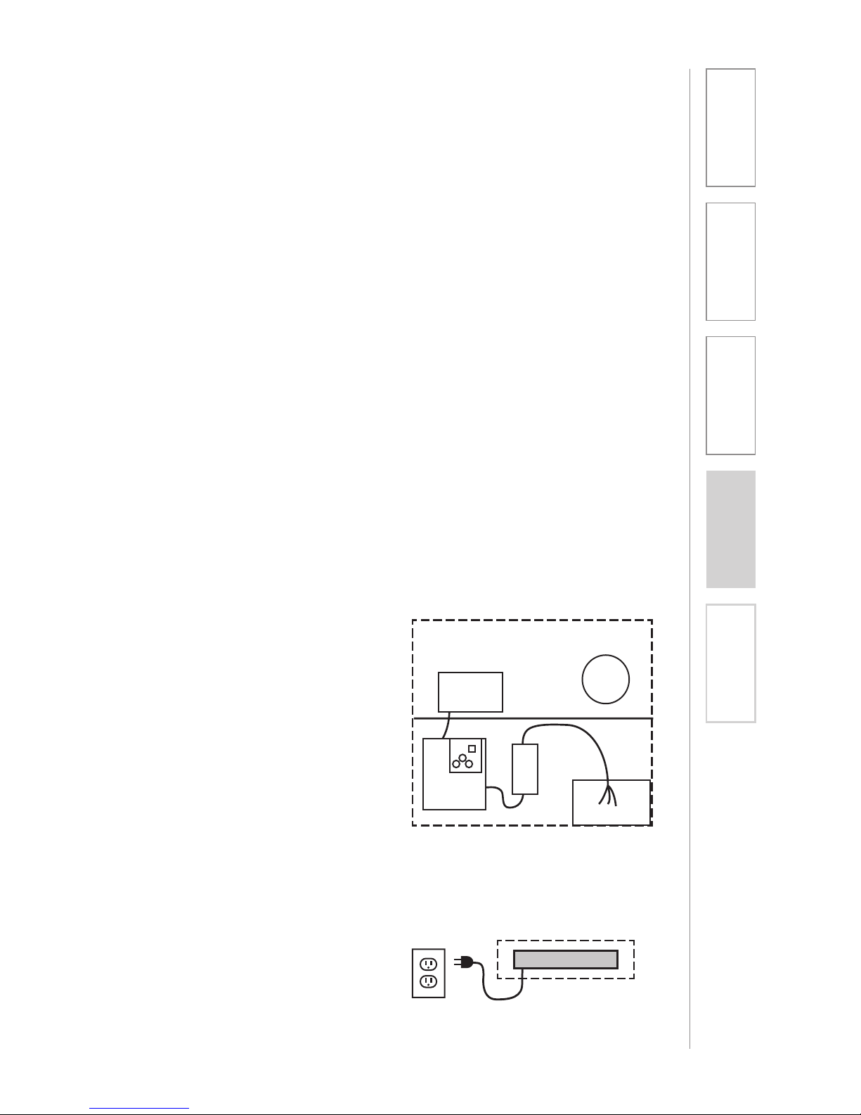
A schematic/wiring diagram of a
typical TOPCAT installation is shown
in the following figure:
NOTE: TOPCAT is designed for
installation in a 2’ x 2’ or 2’ x 4’
suspended ceiling grid (or 600mm x
600mm international ceiling grids). If
you do not have this type of ceiling,
please contact your local Lightspeed
Classroom Audio Consultant.
Audio Mixer/TX/RX
Media Connector Module
Integrated
Sensor/
Receiver
Power
Supply
Amplier/
TX/RX
TOPCAT Module
Page 10
10
1. Overview 2. Installation
3. Optional
Accessories
4. Troubleshooting
5. Warranty, Safety
& Specifications
The TOPCAT is shipped ready to mount in a standard suspended ceiling grid. All
mounting hardware need to secure the TOPCAT in the ceiling is provided except
for that needed to wire the AC power to the chassis.
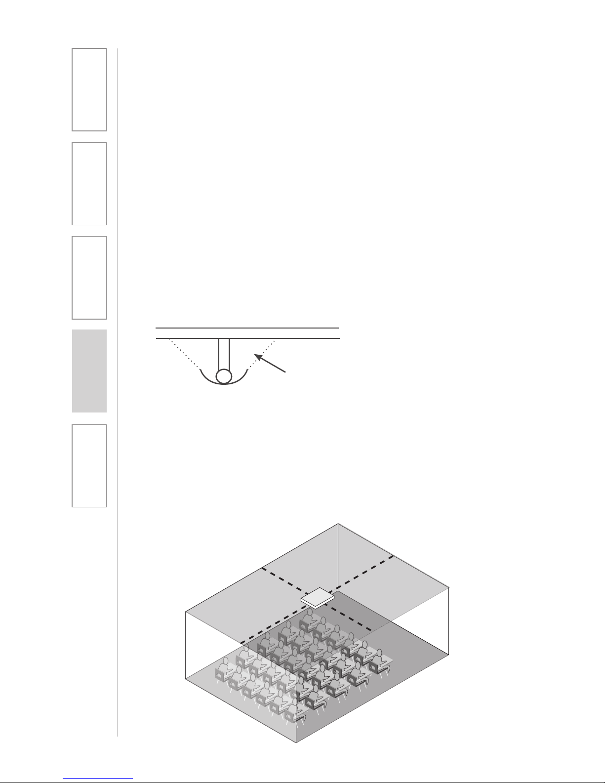
TOPCAT will distribute sound throughout a classroom of up to 1600 square feet.
The location of TOPCAT is critical to ensure even sound distribution.
1. Identify the center of the listening area of the classroom for optimum location.
See Figure 1.
2. Select a ceiling tile that is free of fixtures (lighting, HVAC, etc.) nearest to the
center point.
3. Remove the selected ceiling tile for TOPCAT installation.
NOTE: Do not install where the integrated sensor/receiver (ISR) is in the
reflected light of a hanging light fixture. The ISR can be removed from the
TOPCAT and placed elsewhere on the ceiling or classroom wall.
1. SELECT MOUNTING LOCATION
Fig 1: Identify the Center of the Listening Area
Page 11
11
1. Overview 2. Installation
3. Optional
Accessories
4. Troubleshooting
5. Warranty, Safety
& Specifications
The dimensions of the TOPCAT speaker are 595mm x 595mm and is designed
to lie onto any standard suspended ceiling tile grid. Spacers are attached to
center the TOPCAT in a 2’ x 2’ or 2’ x 4’ ceiling grid. (Remove these spacers when
installing into a 600 x 600 mm grid.)
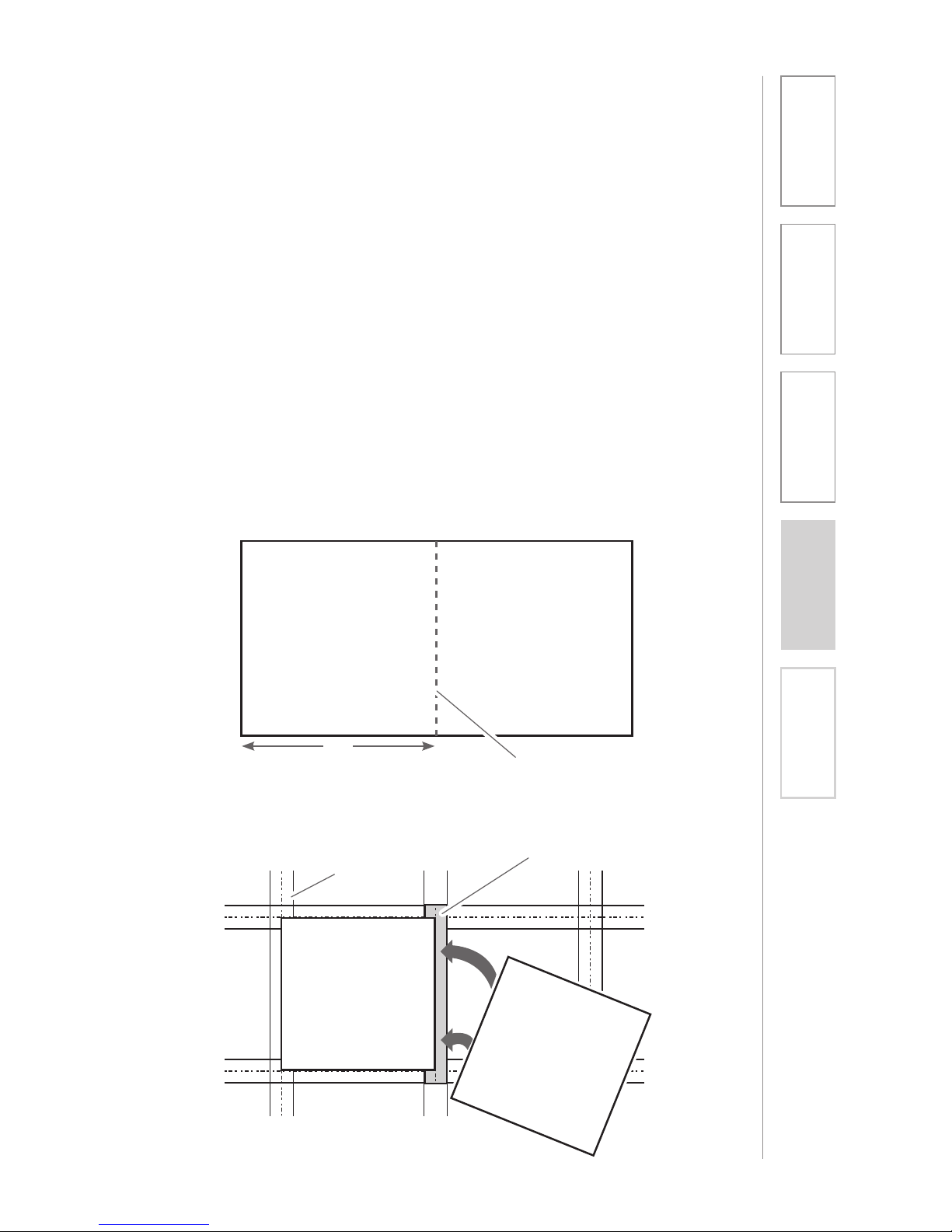
1. If the ceiling tile that was removed is 2’ x 4’, it needs to be cut in half to
accommodate the TOPCAT. If the ceiling tile that was removed is 2’ x 2’, no
cutting of the tile is necessary.
2. Set the ceiling tile on a flat work surface with the patterned side facing down.
3. Using a straight edge, cut the 2’ x 4’ ceiling in half (see figure 2) leaving two 2’
x 2’ sections.
4. Locate the 2’ ceiling grid t-bar attachment. Locate the attachment slots in
the existing ceiling grid and snap the new t-bar into place to crate two 2’ x 2’
openings (see figure 3).
5. Lift the TOPCAT up and lay it into the desired 2’ x 2’ opening in the ceiling.
2. INSTALLING THE TOPCAT INTO THE
CEILING GRID
Figure 2: Cut the 2’ x 4’ Tile in Half
Throw Away Remaining Ceiling Tile
Cut with straight
edge
24”
Figure 3: Create Two 2’ x 2’ Openings
New T-Bar
Existing
Tile Grid
TOPCAT
H
alf
T
ile
Page 12
12
1. Overview 2. Installation
3. Optional
Accessories
4. Troubleshooting
5. Warranty, Safety
& Specifications
3. SECURING THE TOPCAT
To comply with Building Codes, the TOPCAT MUST be fastened to the ceiling
grid and secured with a safety wire.
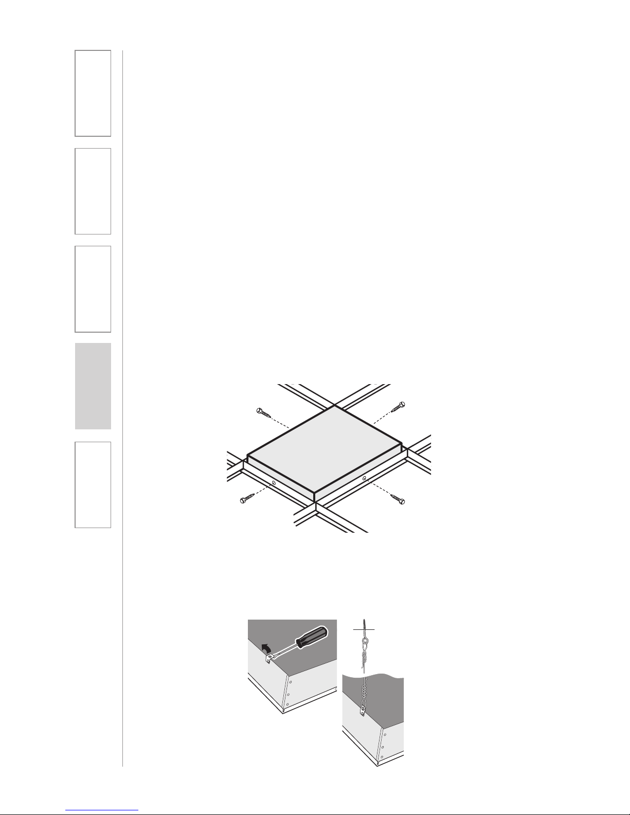
1. Locate the four (4) self-drilling sheet metal screws.
2. Utilizing existing center holes on the vertical section of the ceiling grid, drill
one screw per side on opposite sides of the TOPCAT (see figure 4).
3. Locate the 15ft length of safety wire and the eye screw. The safety wire needs
to be permanently attached to the solid structural ceiling above.
4. Install the eye screw (or concrete anchors if necessary) into the structural
ceiling.
5. Loop one end of the safety wire through the eye screw (or anchor), then twist it
around itself at least five times.
6. Pull one of the tabs up on the TOPCAT rear panel (located in opposite corners)
and loop the other end of the safety wire through the tab. Pull the wire
through until it is taught and twist it around itself at least five times to secure
the speaker. Cut off any excess wire if needed. (see figure 5)
Figure 4: Secure with Self-Drill Screws into the TOPCAT
Figure 5: Looping the Safety Wire Through the Tab
Page 13
13
1. Overview 2. Installation
3. Optional
Accessories
4. Troubleshooting
5. Warranty, Safety
& Specifications
4. INSTALLING AND WIRING ELECTRICAL
POWER
There are two methods of providing power for the TOPCAT.
1. New Construction Installations: Connect directly to the buildings mains AC
power.
2. Retrofit situations: Can either wire to the building mains or order the optional
power extension cable (DCPEX-NA).
SUPPLY POWER TO THE SELECTED LOCATION
WARNING!
USE A CERTIFIED ELECTRICIAN FOR POWER CONNECTIONS.
The TOPCAT System uses standard 100 – 240VAC power. Obtain the services
of a certified electrician when supplying and connecting power to the TOPCAT
chassis. Be sure electrical installation complies with local building codes.
Improperly installing and /or connecting power to the system may result in
Equipment Damage, serious injury and/or Death.
When routing power to the TOPCAT, avoid interference with lighting and other
noise possibilities.
CAUTION:
These servicing instructions are for use by qualified service personnel only. To
reduce the risk of electric shock do not perform any servicing other than that
contained in the operating instructions unless you are qualified to do so.
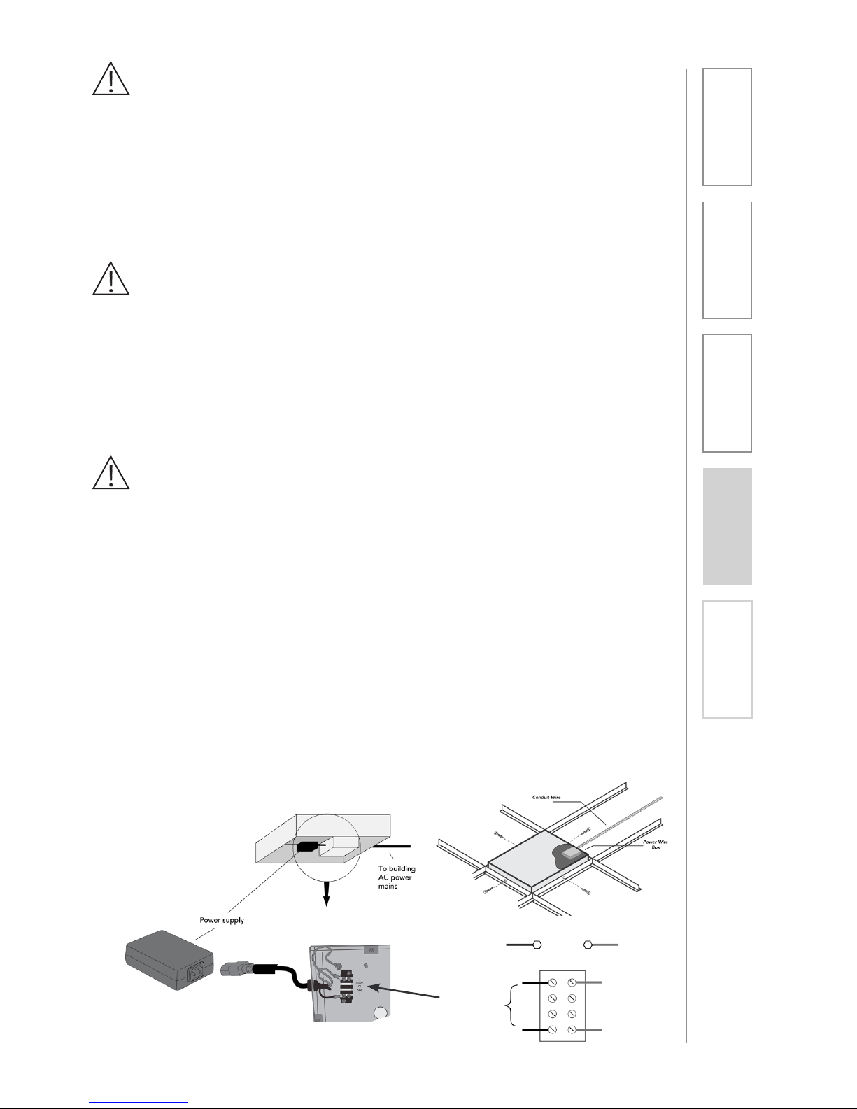
Wire AC power to the TOPCAT as follows:
a. Turn off the current at the main breaker. Attach the electrical wiring to the
TOPCAT Ceiling Module as shown
b. Find the electrical box hole on the TOPCAT back can. Insert the mains
electrical wire through the hole.
c. Find and open the front panel door on the TOPCAT.
d. Remove the lid to the internal electrical box
e. Attach the ground wire to the grounding lug provided. Attach the remaining
two wires to the terminal block screws adjacent to the internal power wires.
f. Replace the lid on the electrical box and turn the electrical current on at the
main switch.
Green Green
Brown
Light Blue
TO
POWER
SUPPLY
100VAC
– 240VAC
Page 14
14
1. Overview 2. Installation
3. Optional
Accessories
4. Troubleshooting
5. Warranty, Safety
& Specifications
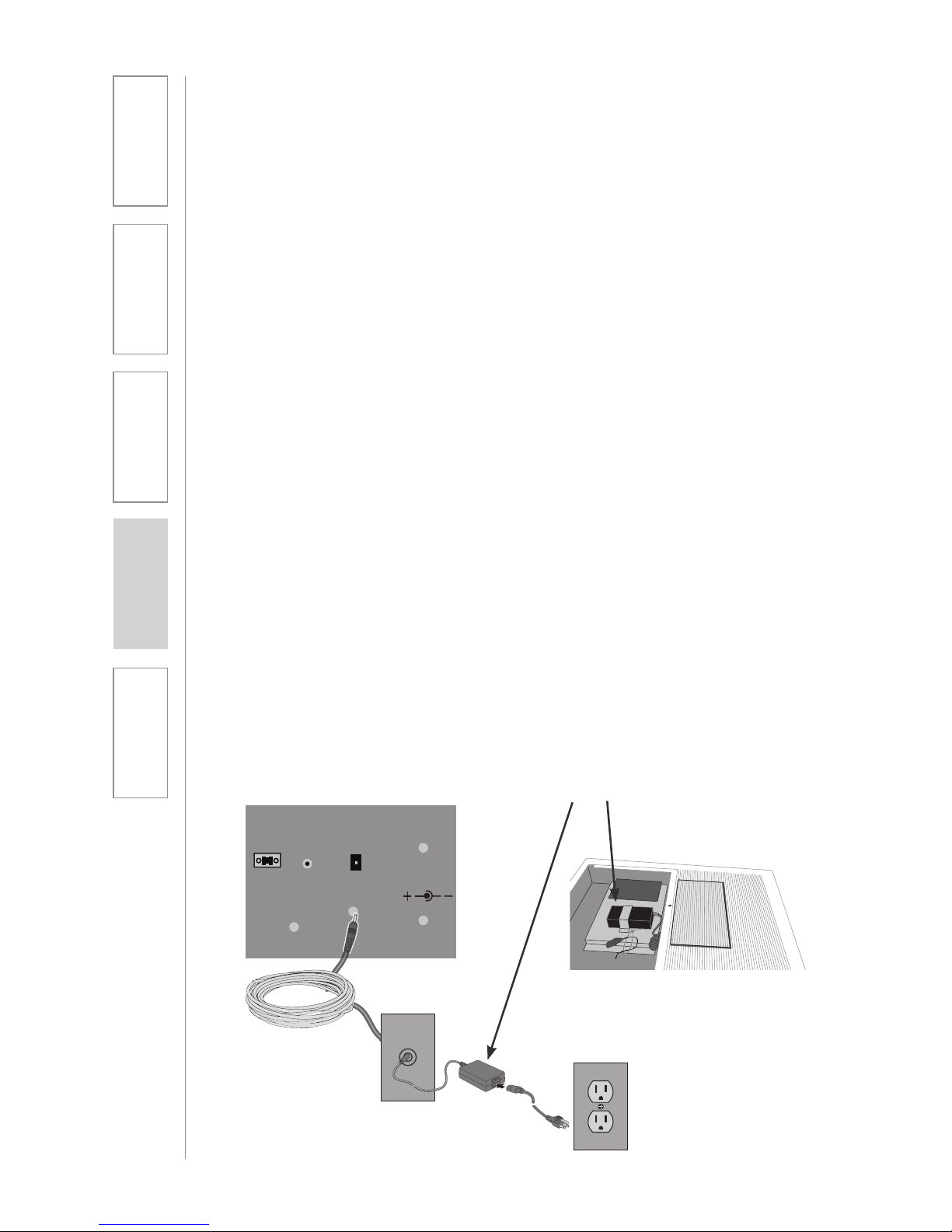
ALTERNATE POWER (OPTIONAL)
When electrical AC power is not available above the ceiling for installation
with the TOPCAT, there is an alternative method for supplying power to the
TOPCAT.
Note: There are two DC Power Connectors for connecting power to the
TOPCAT. Both connectors perform the same function. Use the internal DC
Power Connector located on the amplifier card when AC power is connected
directly to the TOPCAT. Use the connector access located on the outside of
the TOPCAT when using the optional power extender cable.
1. Remove the 24V 2.5A power supply module with its DC power cord that is
secured inside the access door of the TOPCAT.
2. Find the 50’ DC power extender cable (P/N: CA-DCPEX) and plug the
female connector into the side port on the TOPCAT. Use the wire anchor
supplied with the cable to secure the cable to the side of the TOPCAT
chassis. Use the cable tie provided to secure the end of the power cable
remaining in the TOPCAT. This cable should not touch the flat panel speaker
when the door is closed.
3. Route the power extender cable across the ceiling and to the closest
standard AC power outlet. Cable routing should follow all local electrical
codes and installation procedures. (If the power extender cable is to be run
inside the wall, install a mud ring or electrical box in the wall close to the AC
power outlet. If the power extender cable is run on the surface of the wall
using wire molding, then mount a surface mount electrical box to house the
connection of the extender cable and the power supply.)
4. Plug the DC power cable end of the 24V supply into the power extender
cable.
5. Plug the AC power cord into the power supply and into the standard AC
power outlet.
Note: the 50’ power extender cable is plenum rated, suitable for air handling
spaces.
Paging
Input
Aux Power IN
DC: 24V/2.5A
Adj.
Power Supply
50 f. cable
Page 15
15
1. Overview 2. Installation
3. Optional
Accessories
4. Troubleshooting
5. Warranty, Safety
& Specifications
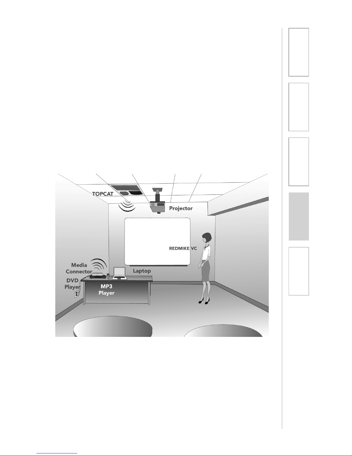
Choose a location for the Media Connector module that is convenient to the
classroom audio sources and power supply.
The MC can be placed on a counter or wall mounted. Determine the best
location for your room. Use the guidelines below when selecting the site.
NOTE: The MC does not require a direct line of sight to the TOPCAT. However it
functions best when no obstructions are between the two devices. Do not place
in an enclosed metal cabinet.
5. LOCATION OF THE MEDIA CONNECTOR
COUNTER OR DESKTOP
• 3-6 feet off of the ground to allow
for good transmission
• Not enclosed in a metal cabinet or
otherwise obstructed.
Page 16
16
1. Overview 2. Installation
3. Optional
Accessories
4. Troubleshooting
5. Warranty, Safety
& Specifications
USB
POWER
AUDIO
VOLUME
AUDIO 1AUDIO 2AUDIO 3AUDIO
4
1.0A5V
Audio Input
AC Power
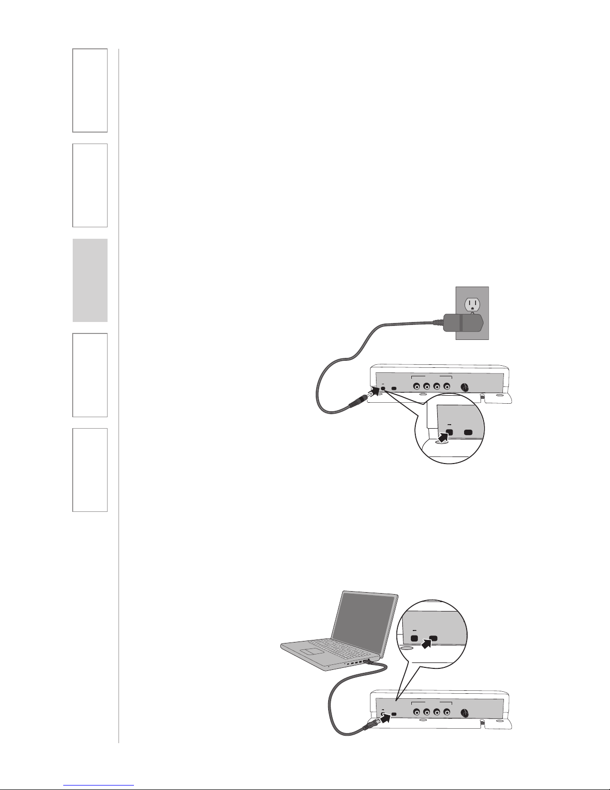
1. Locate the DC port at the rear of
the MC.
2. Place the DC end of power cord
into DC port at the rear of the MC.
3. Place the AC end of power cord
into an electrical outlet.
4. Press the power-on button located
on the front of the MC.
USB Power
If the primary audio source is
a computer, it might be more
convenient to use the supplied USB
cable to power the MC from that
computer.
1. Insert USB cable into MC.
2. Insert USB cable into any available
USB port on the computer.
3. Press the power-on button located
on the front of the MC.
You have now set-up the MC and it is
ready to use.
6. CONNECTING THE POWER SUPPLY
The Media Connector (MC) can be powered in either of two ways:
• ACpowerfromanearbyelectricaloutlet
• USBpowerfromacomputer
Use whichever power source is most convenient to the location of the MC.
USB
POWER
AUDIO
VOLUME
AUDIO 1AUDIO 2AUDIO 3AUDIO
4
1.0A5V
Audio Input
USB
POWER
AUDIO
VOLUME
AUDIO 1AUDIO 2AUDIO 3AUDIO
4
1.0A5V
Audio Input
USB
POWER
AUDIO
VOLUME
AUDIO 1AUDIO 2AUDIO 3AUDIO
4
1.0A5V
Audio Input
Page 17
17
2. Installation
3. Optional
Accessories
1. Overview 4. Troubleshooting
5. Warranty, Safety
& Specifications
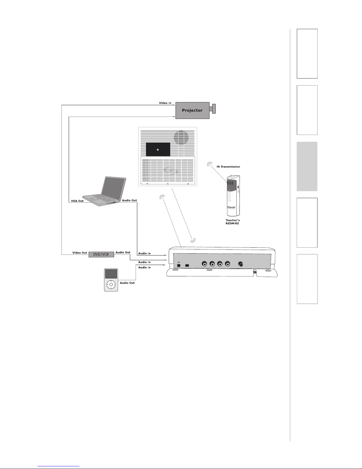
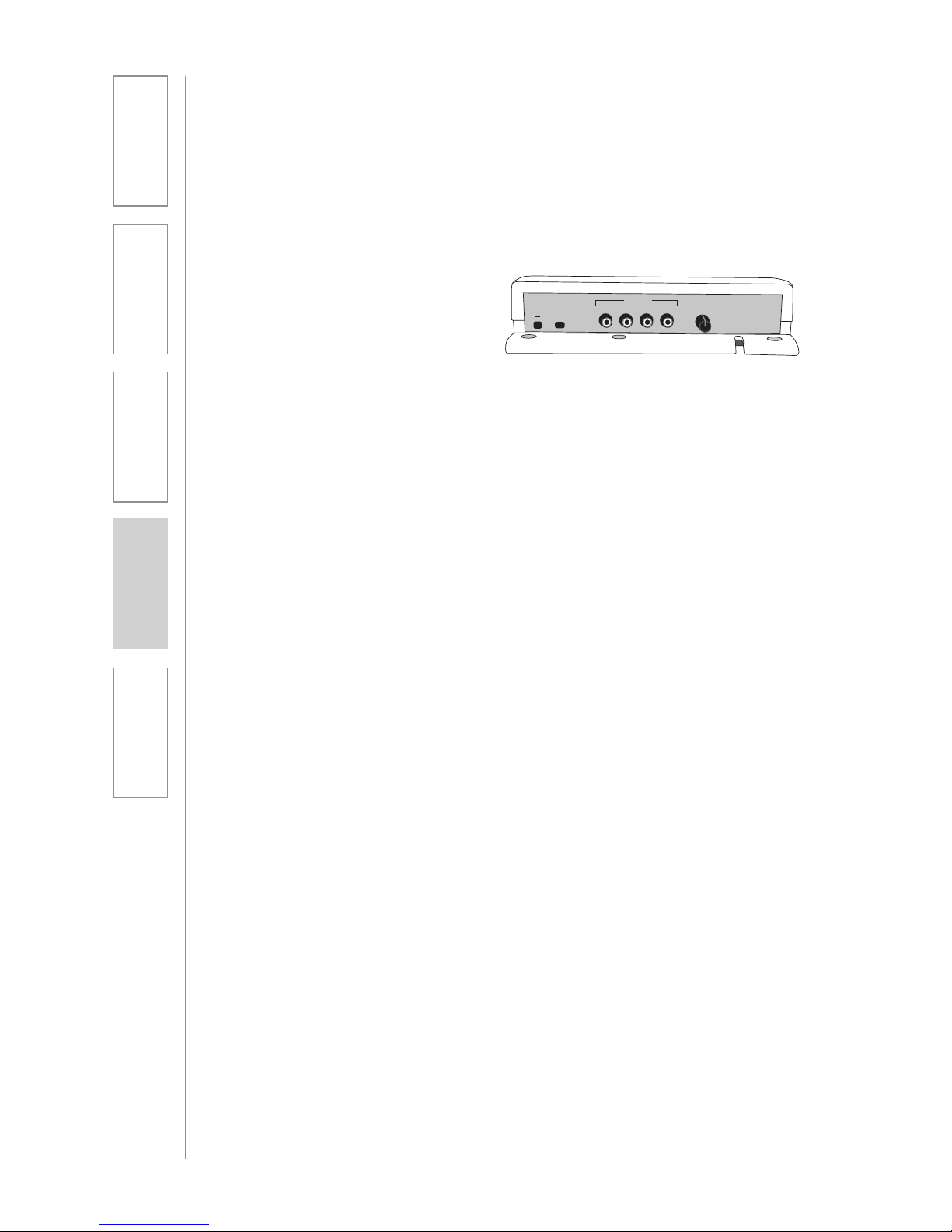
7. AUDIO INTEGRATION
The Media Connector is designed to integrate multiple audio sources quickly
and easily.
USB
POWER
AUDIO
IN
VOLUME
AUDIO 1AUDIO 2AUDIO 3AUDIO
4
1.0A5V
TopCAT
Page 18
18
1. Overview 2. Installation
3. Optional
Accessories
4. Troubleshooting
5. Warranty, Safety
& Specifications
The Media Connector can be used as the primary volume control for the audio
sources you’ve connected.
NORMALIZING AUDIO SOURCE VOLUME CONTROLS
Use the Media Connector as the master audio volume control for the classroom.
When two or more audio sources are connected, you will need to normalize
volume settings by setting all connected audio sources to the same sound level
while leaving the Media Connector volume control set to its center setting. The
Media Connector module is an audio mixer using a master volume control to
adjust the volume of all audio sources at once. Use the following procedure to
set audio source volumes:
1. Connect the audio source(s) to the
Media Connector using the 3.5mm
cables provided
2. Set the audio source volume
to provide sound through the
TOPCAT
3. Use the Media Connector Volume
control to increase or decrease the
sound level.
1. Connect the multimedia audio
sources to the Media Connector
using the 3.5mm cables provided.
2. Set the master volume control on
the Media Connector to its center
position.
3. Turn on an audio source that does
not have an accessible audio level
control. (DVD, VCR player)
4. Adjust the Media Connector
master volume control so the
audio level playing through the
speaker is appropriate for the
classroom.
5. Turn off the first audio source.
6. Turn on the second audio source.
Use its volume control to balance
the audio output to the same
audio level played through the
speaker as the first source.
7. Repeat steps 5 and 6 for the
remaining audio sources.
8. Now, the Media Connector’s
master volume can be used to
increase or decrease the volume
level for all audio sources as
desired.
8. VOLUME ADJUSTMENT FOR THE MEDIA
CONNECTOR
USB
POWER
AUDIO
VOLUME
AUDIO 1AUDIO 2AUDIO 3AUDIO
4
1.0A5V
Audio Input
Page 19
19
1. Overview 2. Installation
3. Optional
Accessories
4. Troubleshooting
5. Warranty, Safety
& Specifications
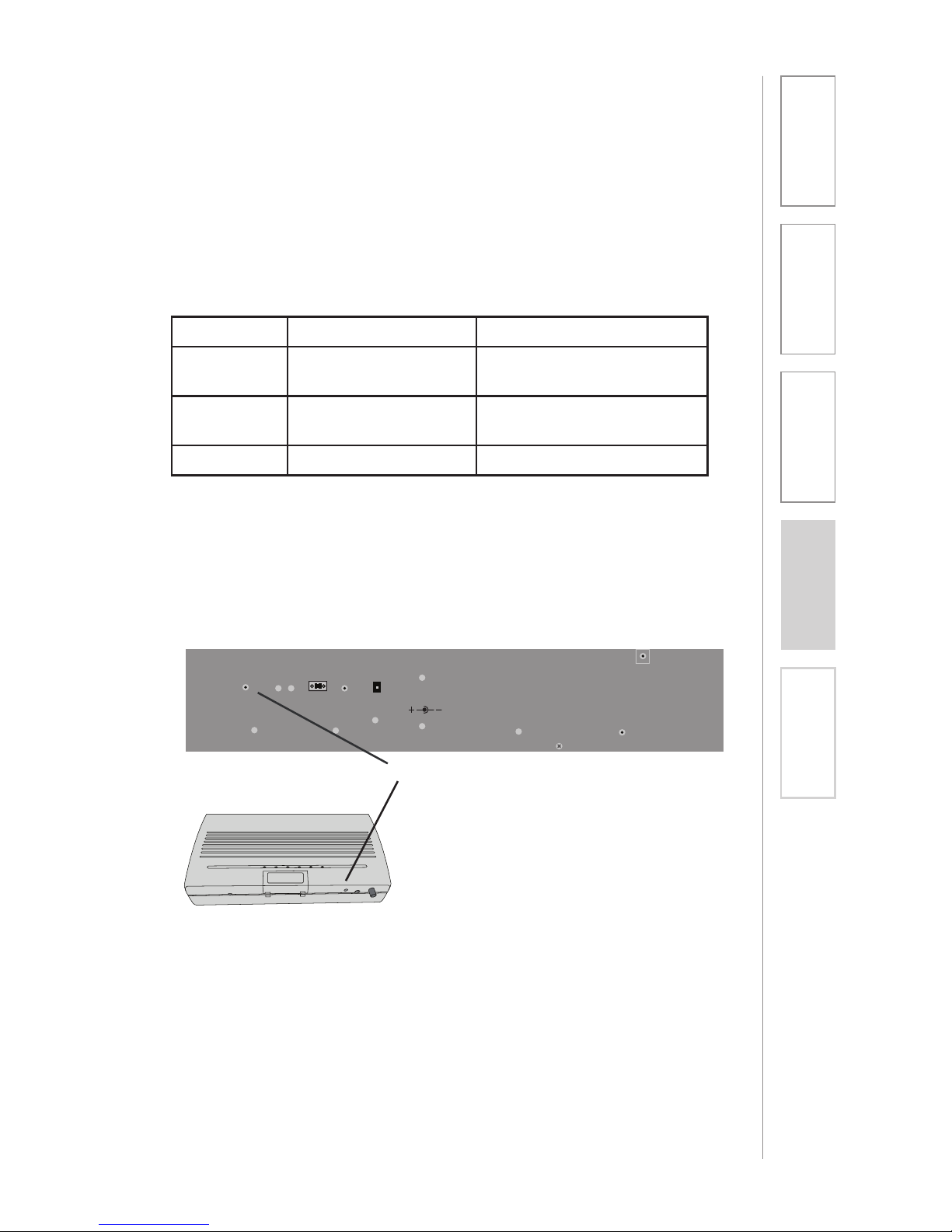
The TOPCAT and Media Connector must be registered or synchronized with
each other before they will operated together. (These modules come preregistered from the factory.) On occasion, one of these modules may be
replaced so the registration process will be needed.
Use the following table to determine if your TOPCAT and Media Connector are
registered.
NOTE: If the link LED on the MC module is continuous green, the following
procedure does not need to be done.
To register TOPCAT with its Media Connector Module:
1. Locate the registration button on the side of the TOPCAT module.
2. Start the procedure by pushing the
registration button. You will have 20
seconds to push the corresponding
registration button on the Media
Connector.
3. Push the registration button on
the Media Connector Module. The
amber LED will begin to blink. When
registration process is complete, the
LINK LED will glow green and the
amber LED will go off.
9. TOPCAT AND MEDIA CONNECTOR
REGISTRATION
Paging
Input
Microphone
Volume
Registration
A B
Aux Power IN
DC: 24V/2.5A
Adj.
TOPCAT
Registration Buttons
NOTE: If after pushing the
Registration button on TOPCAT the
corresponding button on the Media
Connector is not pushed within 20
sec., the amber LED will go from
a slow blinking to a fast blinking.
This means the registration process
has timed out. Wait until the amber
LED stops blinking to start the
registration again.
Media Connector
MC Power MC LINK LED Status
OFF All LEDs Off Turn MC Power ON Blue
LED is LIT
ON Blinking Green Not Linked - Needs to be
registered
ON Continuous Green Linked to TOPCAT
Page 20
20
1. Overview 2. Installation
3. Optional
Accessories
4. Troubleshooting
5. Warranty, Safety
& Specifications
Paging
Input
Microphone
Volume
Registration
A B
Aux Power IN
DC: 24V/2.5A
Adj.
Paging
Input
Microphone
Volume
A B
Aux Power IN
DC: 24V/2.5A
Adj.
10. SETUP AND OPERATION OF THE
REDMIKE VC AND TOPCAT
Once the REDMIKE is charged, follow these steps to set it up for use.
NOTE: This procedure is easier with two people.
1. Turn the TOPCAT power on. The
blue LED on the Media Connector
will glow.
2. Remove the REDMIKE VC from the
charging cradle and turn it on.
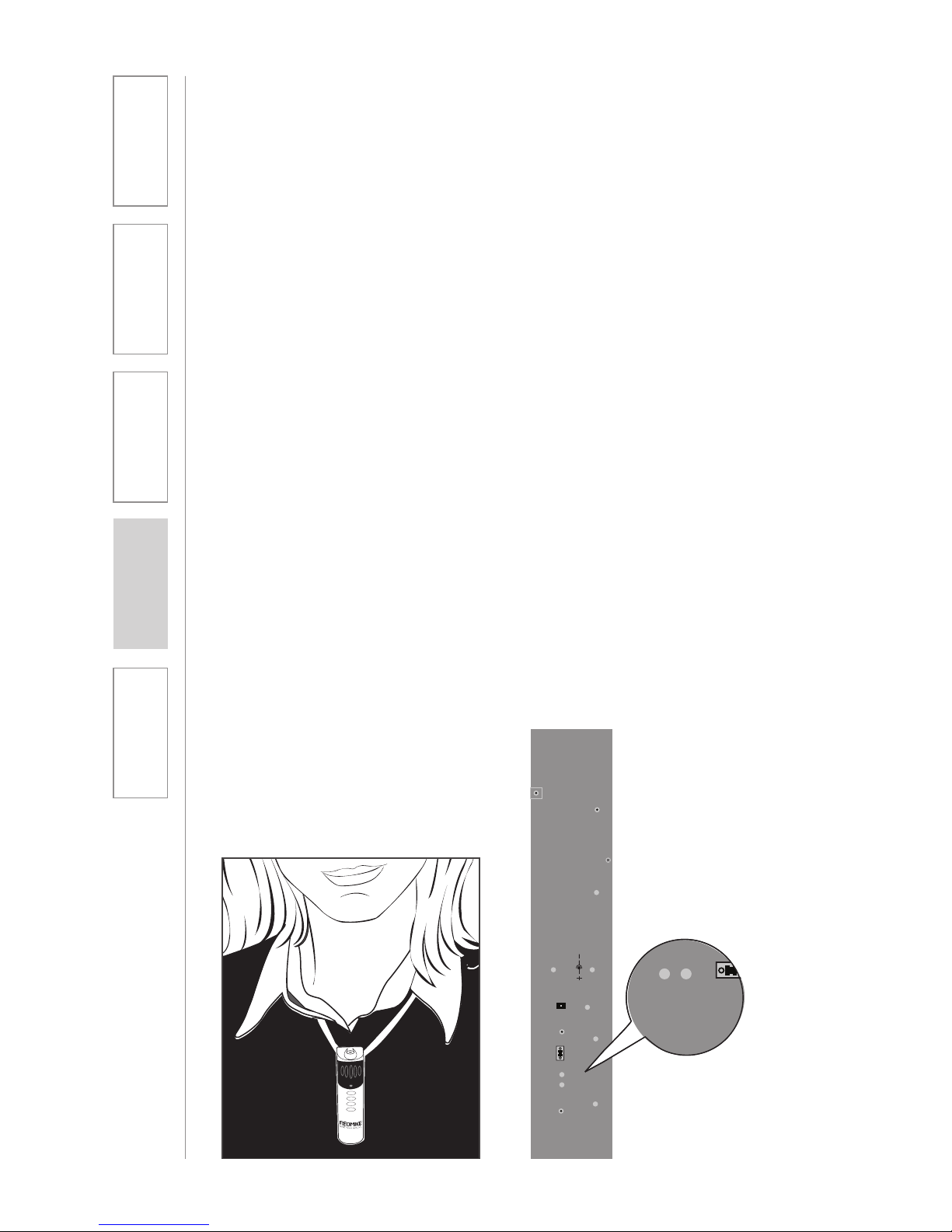
3. Slip the REDMIKE VC with lanyard
around the neck and position the
top of the microphone just below
the collarbone. NOTE: Positioning
of the REDMIKE VC is critical for
proper volume adjustment.
4. Set the REDMIKE VC volume to
its midpoint. Push the up arrow
button 9 times followed by
pushing the down arrow button 4
times. The REDMIKE VC is at its
midpoint.
5. While speaking in a normal voice
slowly increase the volume of the
corresponding channel (A or B)
on the TOPCAT until your voice is
barely audible. Each REDMIKE VC
has its channel pre-set to either A
or B, as indicated on the back of
the Mic.
REMEMBER: This equipment
supplements the user’s voice
so they are able to speak in a
conversational tone. Having the
volume set too high will result in
feedback and listener fatigue.
6. Once initial volume level is set,
walk around the room and listen
for audio dropout and overall
audio quality.
Note: A nominal volume level
must be set on the TOPCAT
before adjusting controls on the
REDMIKE VC.
7. The teacher can now use the
controls on the REDMIKE VC
to adjust the volume level from
anywhere in the room. The
microphone volume control has 4
steps up and 4 steps down from
the mid point (9 levels total).
6. If a second REDMIKE VC was
purchased, repeat steps 2-5.
Page 21

21
1. Overview 2. Installation
3. Optional
Accessories
4. Troubleshooting
5. Warranty, Safety
& Specifications
• Speakinanaturalvoice.Anormal
conversational speech level will
provide an adequate signal.
It is not necessary to increase
the intensity of your voice—the
audio system provides adequate
amplification (approximately 5 – 10
dB) above ambient room noises.
• Avoidwearingjewelrythatmayrub
or bump against the microphone.
• TurntheREDMIKEVCoffduring
private conversations with a
student, parent, or other classroom
visitor. You can also cover the LED
lens on top of the REDMIKE VC to
block the signal.
• Rechargebatterieseachnight.
When recharged nightly, operating
time (actual usage) for the
transmitters will last through a
typical school day.
TIPS TO OBTAIN OPTIMUM AUDIO
PERFORMANCE
Page 22
22
1. Overview 2. Installation
3. Optional
Accessories
4. Troubleshooting
5. Warranty, Safety
& Specifications
11. CHARGING THE REDMIKE VC
Before use, the REDMIKE VC should be charged. It will take 8-9 hours for the
REDMIKE VC to obtain a full charge. A fully charged REDMIKE VC will last for
over 7 hours of use. If microphones are used daily, they should be kept in the
cradle – microphones can be left in a charging cradle constantly for up to 2
weeks without causing degradation to battery life.
A red light on the charging cradle indicates the REDMIKE VC is charging.
A green light indicates that charging is complete and a full charge has
been reached. A blinking light indicates a charging or sensing error. See
Troubleshooting section for more information.
REDMIKE VC incorporates alkaline protection into the microphone design.
Always use a Lightspeed rechargeable sensing battery. Replacement AA NiMH
batteries may only be purchased through Lightspeed Technologies (part # BANH2A27). Do not attempt to charge alkaline batteries. They can overheat and
expand creating a significant hazard and damaging the microphone (this is not
covered by warranty).
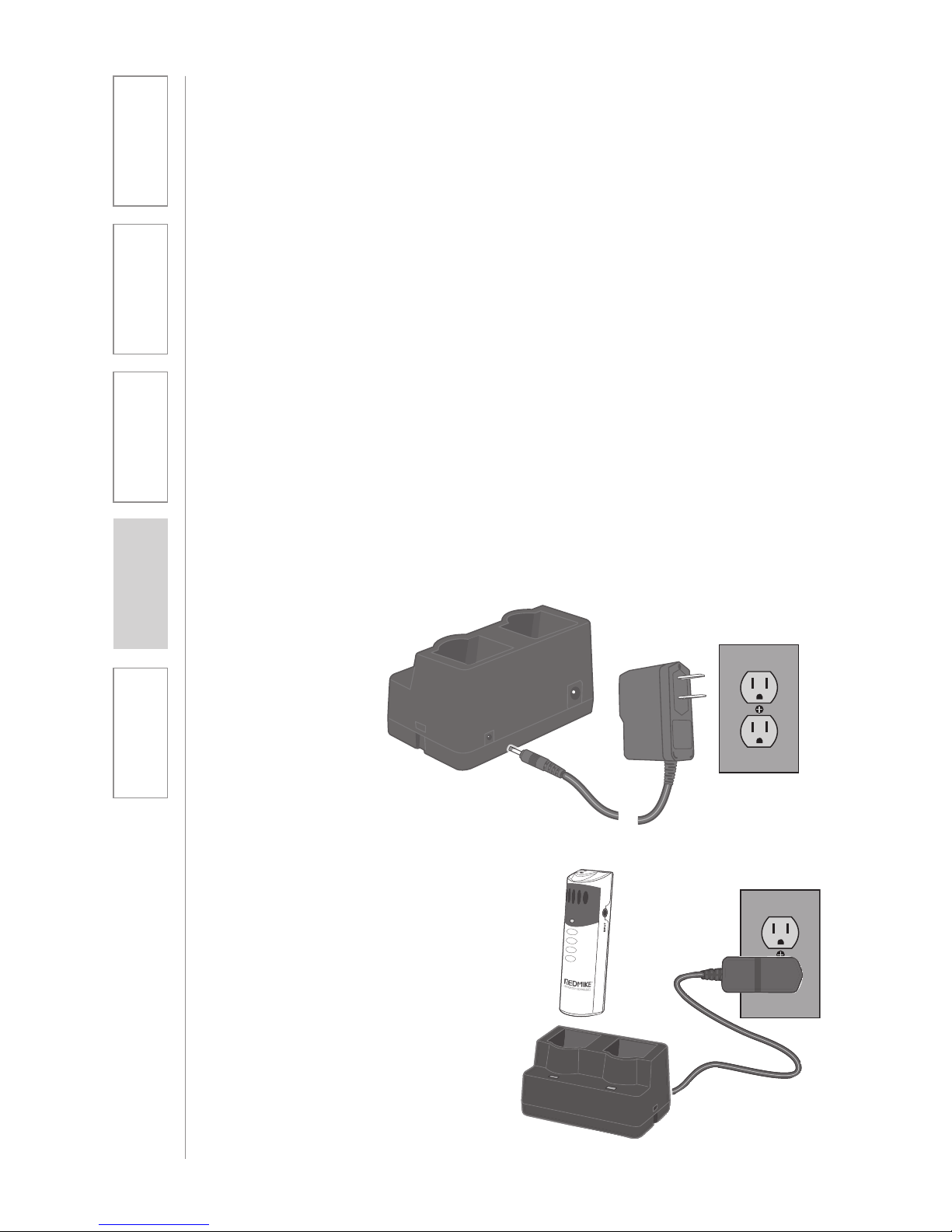
1. Plug power cord into the cradle
charger and then plug the AC end
into an electrical outlet.
2. Ensure that the REDMIKE VC is
turned OFF.
3. Place the REDMIKE VC into the
cradle. The LED on the cradle
will glow RED indicating charging
has started. When the REDMIKE
VC is fully charged the LED on
the cradle charger will change to
GREEN.
Page 23
23
1. Overview 2. Installation
3. Optional
Accessories
4. Troubleshooting
5. Warranty, Safety
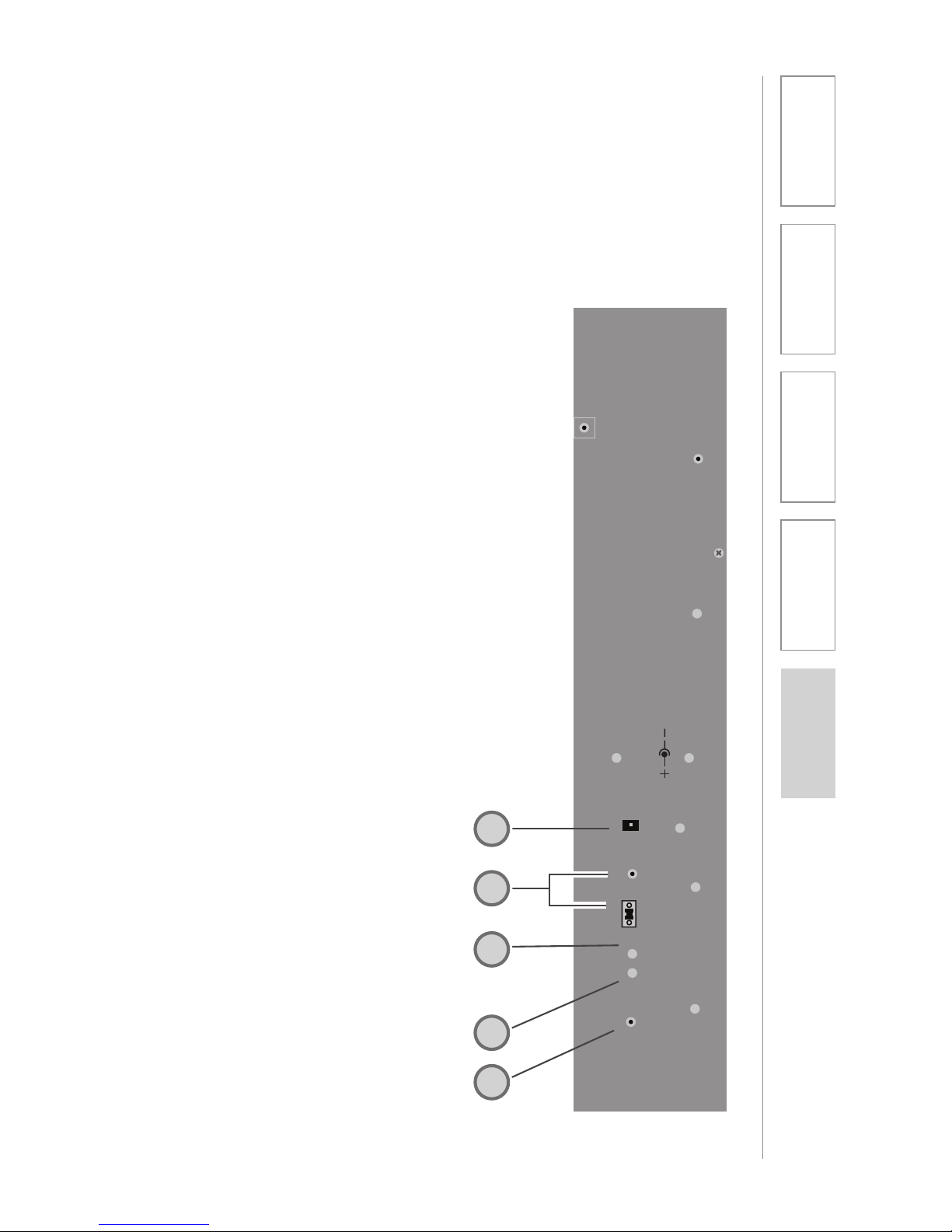
& Specifications
SIDE PANEL CONTROLS AND
CONNECTIONS
1. CH A VOLUME: Controls the
volume level for microphone set
to channel A. It is preset at the
factory to its 12 O’clock position.
Turn clockwise to increase volume
or counter clockwise to decrease
volume.
2. CH B VOLUME: Controls the
volume level for microphone
set to channel B. Turn clockwise
to increase volume or counter
clockwise to decrease volume.
3. AUX POWER INPUT
CONNECTOR (OPTIONAL):
For use during installations where
AC power is not available in the
ceiling. Accepts 24VDC, 2.5A
connector from an external power
supply.
4. PAGEFIRST INPUT AND ADJUST:
Connect the input from optional
PageFirst sensor when interfacing
with the buildings paging system.
Use the ADJ control to adjust the
sensitivity if needed.
5. REGISTRATION BUTTON: This
button is used to synchronize
the TOPCAT with the Media
Connector Module.
Paging
Input
Microphone
Volume
Registration
A B
Aux Power IN
DC: 24V/2.5A
Adj.
4
3
2
5
1
SIDE VIEW
Page 24
24
1. Overview 2. Installation
3. Optional
Accessories
4. Troubleshooting
5. Warranty, Safety
& Specifications
USB
POWER
AUDIO
VOLUME
AUDIO 1AUDIO 2AUDIO 3AUDIO
4
1.0A5V
Audio Input
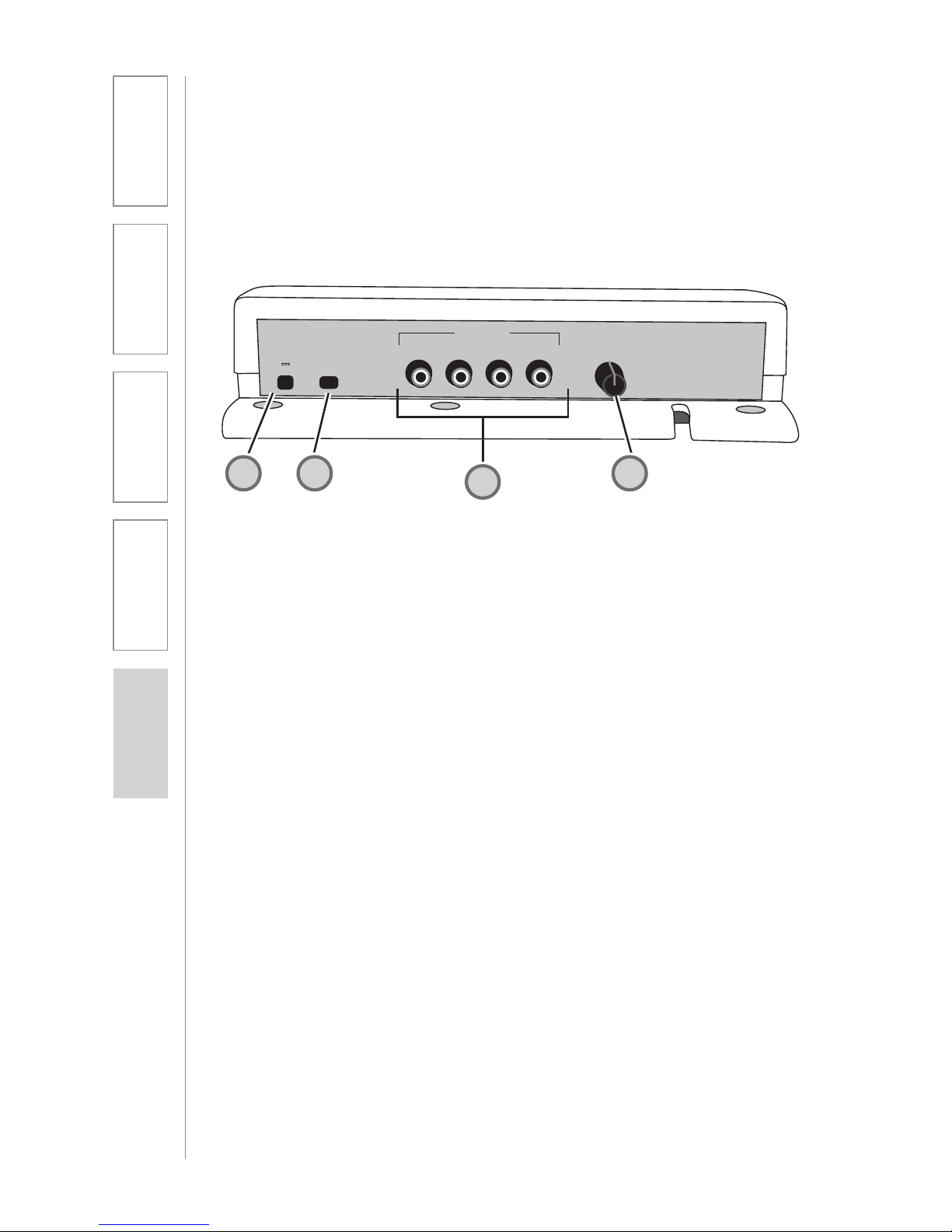
1. POWER CABLE INPUT: When
using an AC outlet, plug the power
supply (5V/1.0A) in to this jack.
2. USB POWER INPUT: Alternatively,
use the provided USB cable to
power the Media Connector from
a USB-enabled computer.
3. FOUR AUDIO INPUTS: Connect
standard audio devices to any
of the 3.5mm stereo inputs. A
provided cable allows connectivity
to RCA stereo outputs common on
DVD players and televisions
4. VOLUME CONTROL: Controls
the output volume of the media
connector. Factory pre-set for most
applications.
MEDIA CONNECTOR FRONT PANEL
CONTROLS
4
2
1
2
3
Page 25
25
1. Overview 2. Installation
3. Optional
Accessories
4. Troubleshooting
5. Warranty, Safety
& Specifications
POWER
REGISTRATION
ALD OUT
LINK
REGISTR
POWER
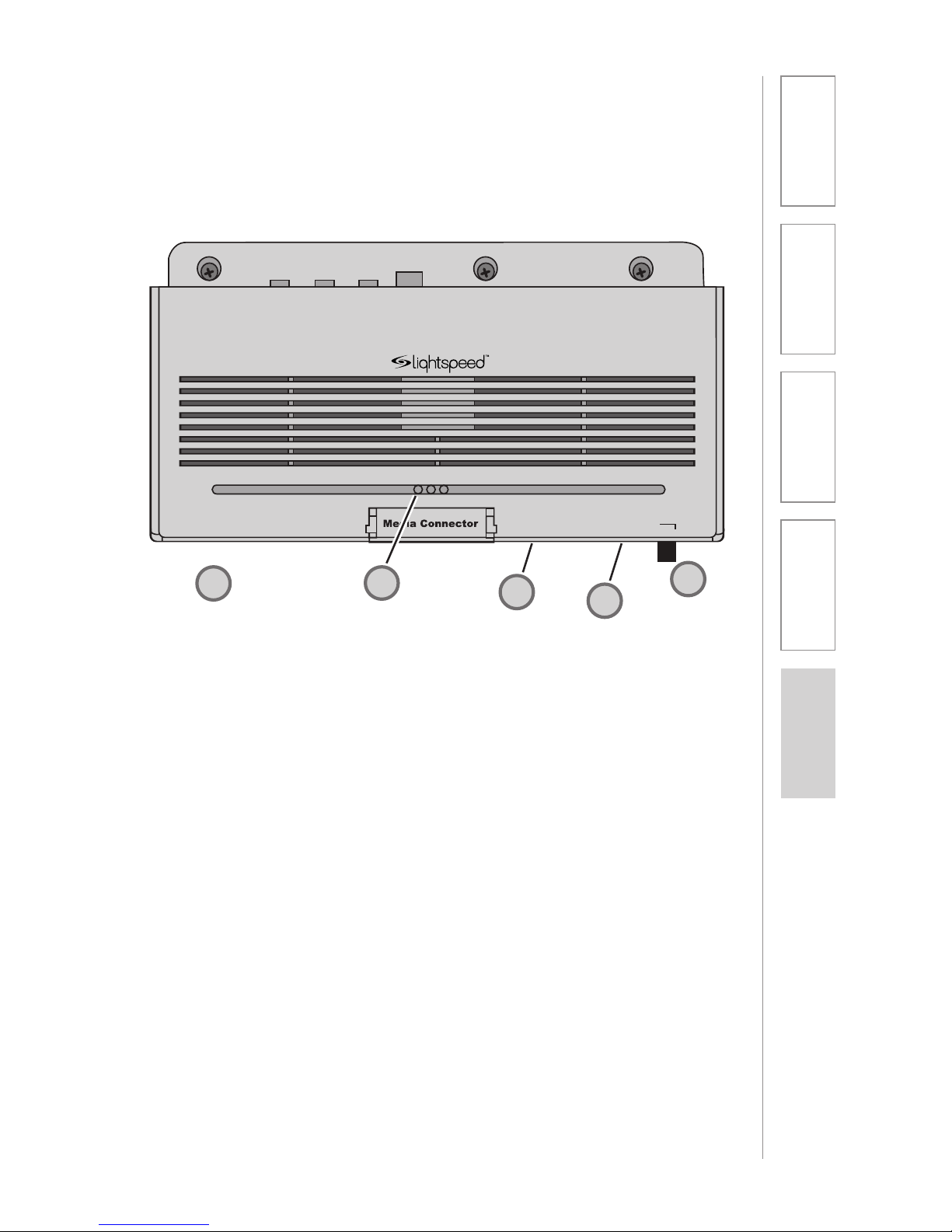
MEDIA CONNECTOR REAR PANEL
CONTROLS
1. SYSTEM POWER SWITCH:
System power is turned ON or
OFF with this pushbutton. When
power is ON, the blue power LED
lights.
2. REGISTRATION PUSHBUTTON:
Pushing the Registration button in
conjunction with the registration
button on the TOPCAT module
will cause the two modules to
synchronize as an operating
system. Refer to the Registration
Procedure in this manual.
3. ALD AUDIO OUTPUT: 3.5mm
stereo jack sends audio signal
to external equipment such as a
recorder or an assistive listening
device like Lightspeed’s LES-370
personal FM system.
4. ALD AUDIO VOLUME
CONTROL: Adjusts the audio
signal level output through the
ALD audio output connector.
5. RF LINK LED: This LED is lit
anytime the RF link is established
between Media Connector and the
TOPCAT. This LED will glow green
while the system modules remain
linked.
1
3
4
2
2
5
Page 26
26
1. Overview 2. Installation
3. Optional
Accessories
4. Troubleshooting
5. Warranty, Safety
& Specifications
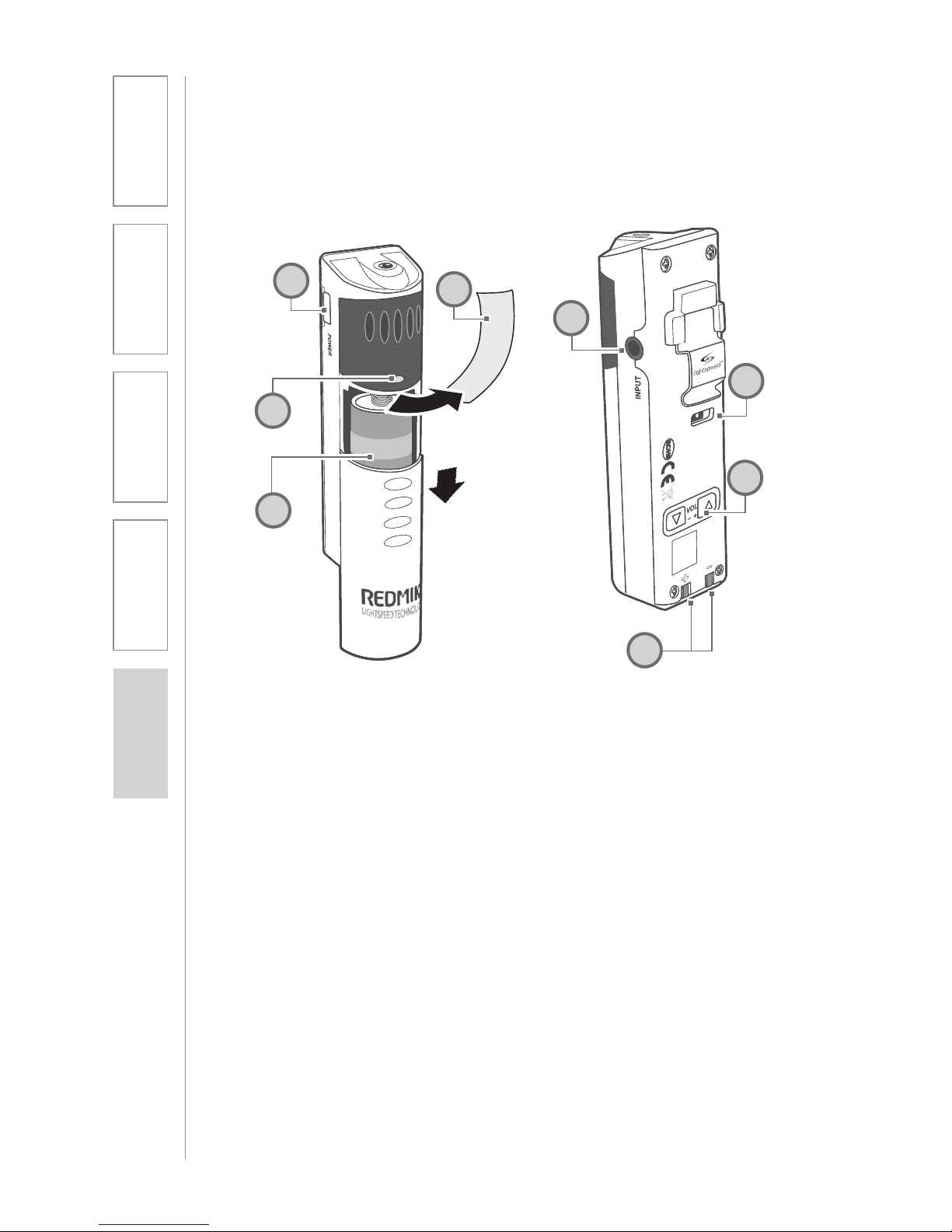
REDMIKE VC (Volume Control) CONTROLS
AND CONNECTIONS
1
2
3
S
l
i
d
e
b
a
t
t
e
r
y
d
o
o
r
o
p
e
n
R
e
m
o
v
e
t
a
b
b
e
f
o
r
e
u
s
e
4
1. POWER /MUTE BUTTON
2. POWER/LOW BATTERY
INDICATOR: A BLUE light
indicates the REDMIKE VC is on
and fully charged. A RED light
indicates a charge is needed.
3. BATTERY COMPARTMENT: To
open, slide the door downward.
The battery should only be
replaced by a Lightspeed AA
rechargeable sensing battery
(part # BA-NH2A27).
4. YELLOW PROTECTIVE TAB:
Slide the battery compartment
door and remove this disposable
protective tab before use.
5. AUDIO/MICROPHONE INPUT:
Use this input to plug in a laptop,
MP3 player or other audio
source to wirelessly transmit
audio to be played through the
system. Alternatively, an external
microphone can be connected.
6. CHANNEL SELECT SWITCH (CH
A/B): Use this to choose Channel
A or B. If you are using a single
microphone, we recommend using
Channel A.
7. VOLUME CONTROLS (UP DOWN)
8. CHARGER CONTACTS (+ -):
These contacts interface with the
charging tabs when the REDMIKE
VC is placed in the BC-RMCC
cradle charger.
5
6
7
8
Page 27
27
1. Overview 2. Installation
3. Optional
Accessories
4. Troubleshooting
5. Warranty, Safety
& Specifications
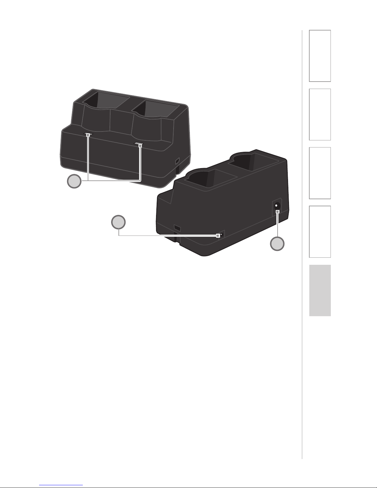
1. CHARGE INDICATORS: The light
glows RED while the REDMIKE is
charging. When fully charged, the
light will glow GREEN. A blinking
RED light indicates that no battery
is sensed, (REDMIKE Yellow
Protective Tab may not have been
completely removed—see page
5, item 4.) A blinking Green LED
means a non- Lightspeed battery
has been installed (possibly an
alkaline battery).
2. DC POWER PORT: Connect the
DC power cord here.
3. OPTIONAL CHARGING PORT:
Plug the charging cord for the
optional the REDMIKE Share
microphones here.
CRADLE CHARGER CONTROLS AND
CONNECTIONS
1
2
3
Page 28
28
1. Overview 2. Installation
3. Optional
Accessories
4. Troubleshooting
5. Warranty, Safety
& Specifications
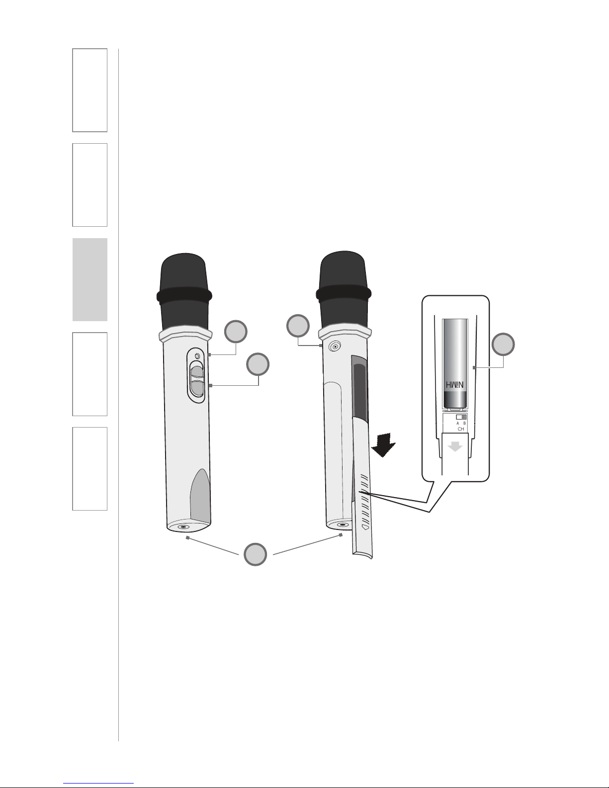
1. POWER SWITCH:
2. POWER/CHARGE INDICATOR:
this light glows blue when turned
on and turns off to indicate low
battery level. When charging, the
light glows red.
3. AUDIO INPUT: plug a laptop, MP3
player or other audio device into
this jack to wirelessly transmit the
audio signal to be played through
the system.
4. CHANNEL SELECT SWITCH
(CH A/B): Located in the battery
compartment, this switch is set to
Channel B at the factory.
5. CHARGER INPUT: Plug the
charging cable from the REDMIKE
cradle charger or into this jack.
REDMIKE SHARE: CONTROLS AND
CONNECTIONS
1
2
3
5
4
SECTION 3:
OPTIONAL
ACCESSORIES
Page 29
29
2. Installation
3. Optional
Accessories
1. Overview 4. Troubleshooting
5. Warranty, Safety
& Specifications
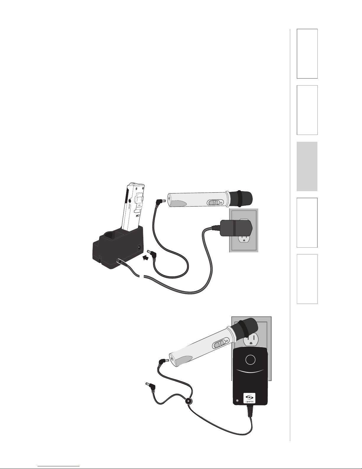
NOTE: If the system was purchased
without a REDMIKE or REDMIKE VC,
the REDMIKE Share will utilize the
BC-TXLT wall charger. Plug the wall
charger into an AC outlet and plug
the other end(s) into the CHARGER
jack on the REDMIKE Share.
1. Ensure that the REDMIKE Share is
turned OFF.
2. Make sure the cradle charger
is plugged into a wall outlet.
Connect one end of the charging
cable into the jack labeled
CHARGER on the bottom of the
REDMIKE Share.
3. Plug the other end into the
charging jack on the rear of the
cradle charger.
4. The LED on the microphone will
glow RED to indicate charging.
5. Leave the REDMIKE Share
plugged in overnight (8-10 hours)
to obtain a full charge.
REDMIKE SHARE: CHARGING
Before use, the REDMIKE Share should be charged. It will take 8-9 hours for
the REDMIKE Share to obtain a full charge. A fully charged REDMIKE Share
will last for over 7 hours of use. If the microphone is used daily, it should
be kept plugged into the charging cradle - REDMIKE Share can be left in a
charging cradle for up two weeks without causing degradation to battery life.
Page 30
30
1. Overview 2. Installation
3. Optional
Accessories
4. Troubleshooting
5. Warranty, Safety
& Specifications
REDMIKE SHARE: INITIAL SET-UP
1. Ensure the TOPCAT is ON. The
blue LED on the Media Connector
will glow.
2. Turn on the REDMIKE Share
by sliding the switch to the top
position.
3. Grip the barrel in the center
section. Avoid covering the
infrared emitters just below the
microphone grille. This could
interrupt signal transmission.
4. While speaking in a normal voice,
increase the CH. B VOLUME on
the TOPCAT level until your voice
is barely audible.
OPTIONAL PAGEFIRST INTERFACE
This optional feature interfaces with an independent classroom paging system.
When the page is broadcast, all audio from the system is muted, ensuring
important and even emergency school-wide messages are never missed.
REMEMBER: This equipment is designed to supplement and distribute the user’s
voice so they are able to speak in a conversational tone. Having the volume set
too high will result in feedback and listener fatigue.
(For full installation details refer to the install sheet included with the optional
PageFirst sensor clip)
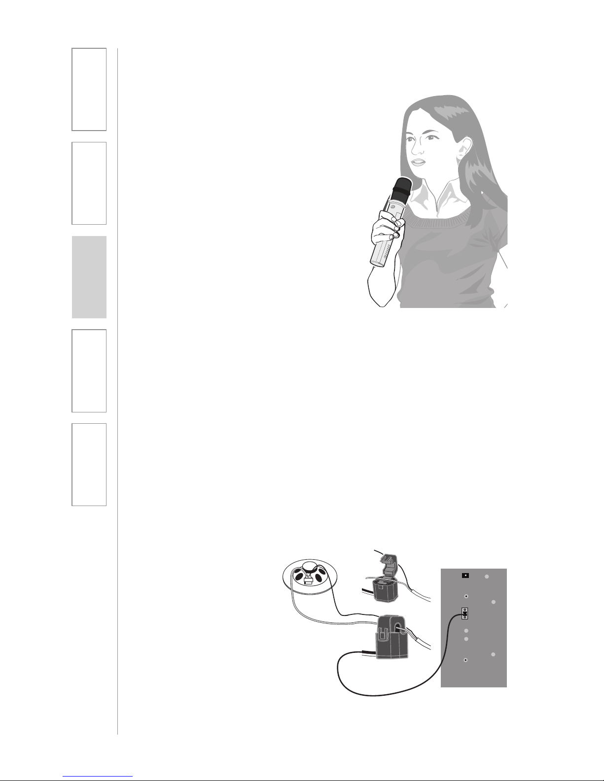
How it works:
1. PageFirst sensor clip is hung
around the lead wires attached
to the classroom paging
speaker.
2. The clip is hard-wired to the
TOPCAT.
3. As a page is broadcast, the
sensor clip detects the audio
signal through induction and
immediately mutes the TOPCAT.
4. When the page is over, the audio
from the TOPCAT returns to
normal volume level.
Paging
Input
Microphone
Volume
Registration
A B
Aux Po
wer IN
DC: 24V/2.5A
Adj.
Page 31
31
2. Installation
3. Optional
Accessories
1. Overview 4. Troubleshooting
5. Warranty, Safety
& Specifications
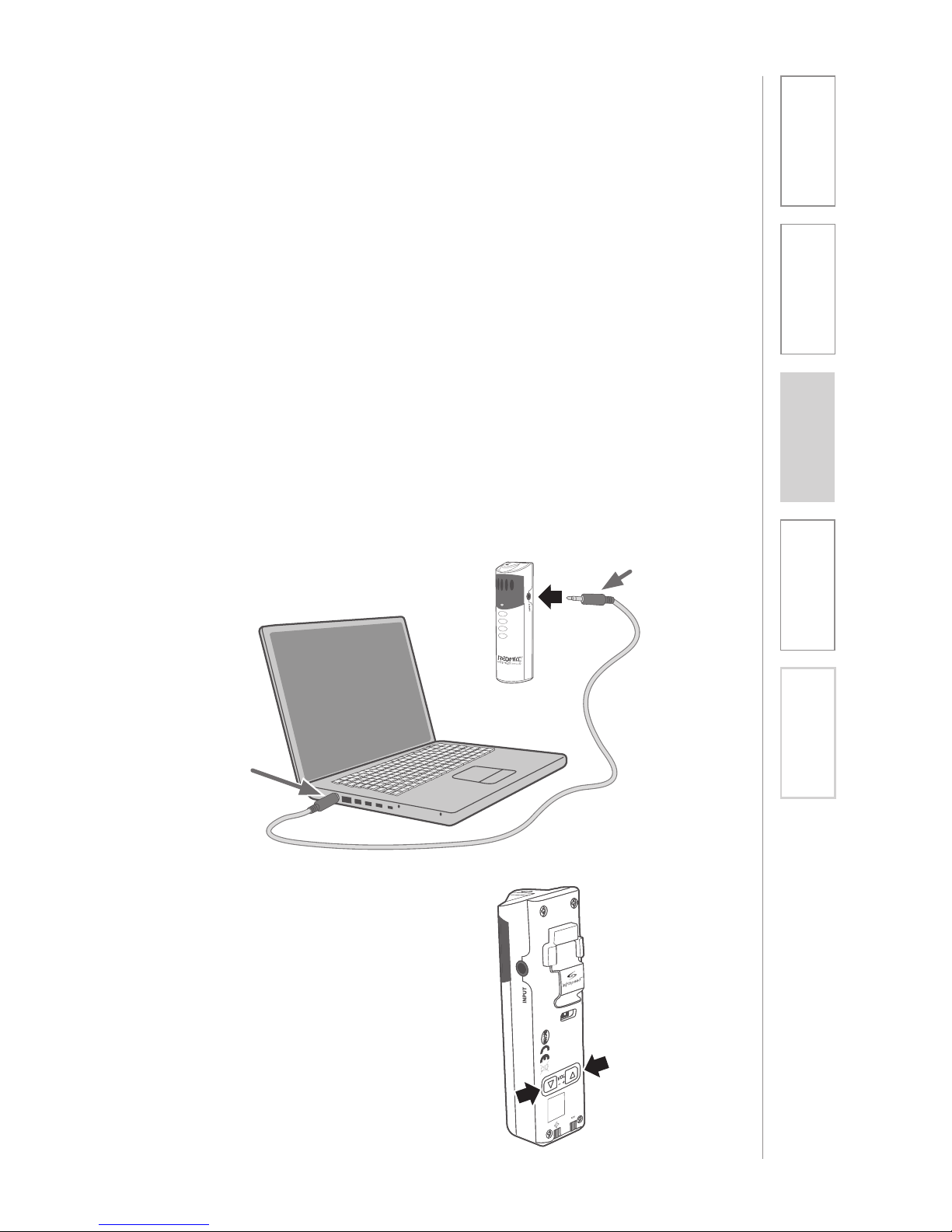
USING THE REDMIKE VC TO AMPLIFY
EXTERNAL AUDIO EQUIPMENT
The REDMIKE includes a 3.5mm audio input jack to connect to an audio source
like a laptop or MP3 player. The REDMIKE VC will transmit the audio signal to be
played through the system.
If your system includes two REDMIKE VCs, we recommend using Channel B
(student mike) to amplify the external audio equipment so the teacher’s volume
on the Channel A (teacher mike) does not have to be adjusted.
To determine which REDMIKE VC is set to Channel B, you can look at the switch
on the back of the mike.
1. Plug your external audio
equipment (for example, laptop),
into the input on the REDMIKE VC
labeled “INPUT” using a 3.5mm
patch cable.
2. Adjust the volume of the
REDMIKE VC to achieve desired
loudness.
AUDIO
OUTPUT
AUDIO
INPUT
Page 32
32
1. Overview 2. Installation
3. Optional
Accessories
4. Troubleshooting
5. Warranty, Safety
& Specifications
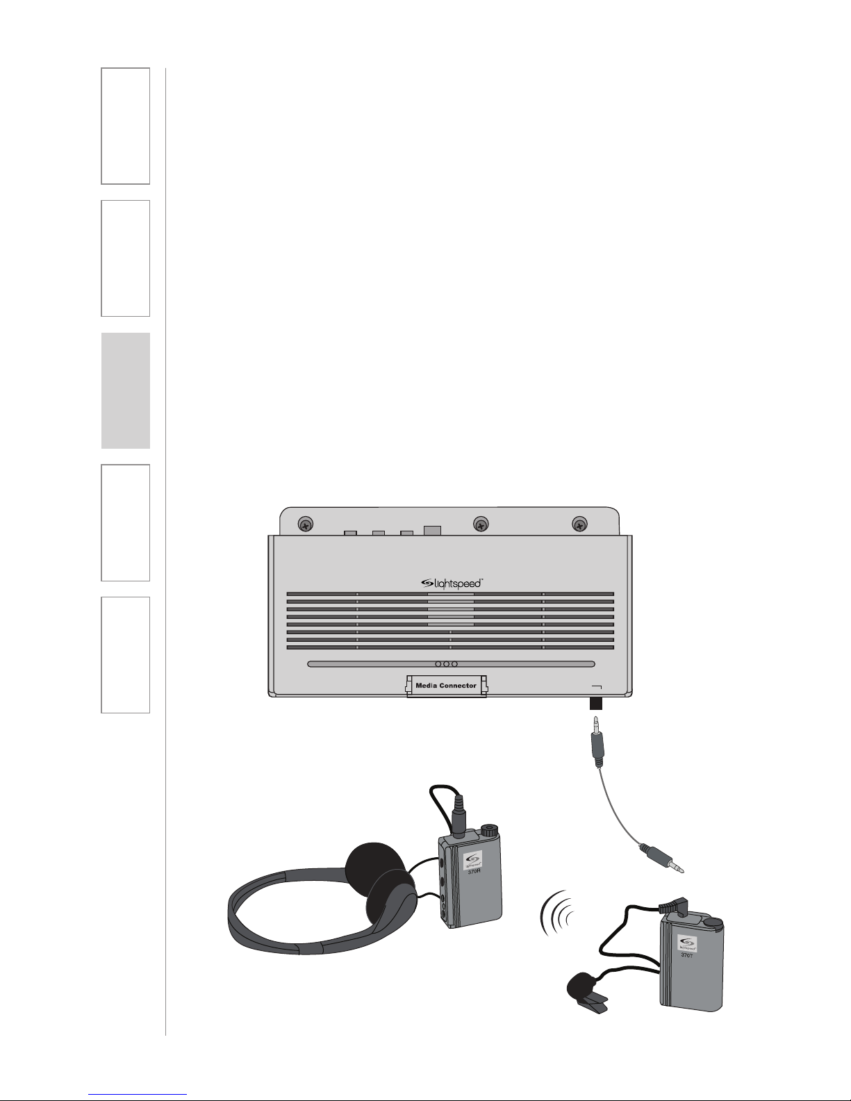
1. Turn the ALD (Assistive Listening
Device) volume control on the
Media Connector front panel all
way the down.
2. Determine the size and type of
audio input jack on the device as
many manufacturers’ products
differ in connector size and shape.
The Lightspeed LES-370 Personal
FM System requires a 3.5mm to
3.5mm patch cable (part# CAMMC3535, not included).
3. Connect a patch cable from the
ALD’s microphone jack or AUX
input to the 3.5mm audio jack
labeled “ALD OUT” on the front
of the Media Connector.
4. Adjust the volume control on the
ALD’s receiver to maximum output.
NOTE: This is to set the maximum
allowable signal from
the Media Connector.
5. With the TOPCAT and ALD turned
on, speak into the REDMIKE VC
and slowly adjust the ALD
volume control until the
appropriate audio level is
attained in the ALD’s receiver
headphones.
OUTPUT TO ASSISTIVE LISTENING
DEVICE (ALD)
POWER
REGISTRATION
ALD OUT
LINK
REGISTR
POWER
ALD Receiver
ALD Transmitter
Page 33
33
2. Installation
3. Optional
Accessories
1. Overview 4. Troubleshooting
5. Warranty, Safety
& Specifications
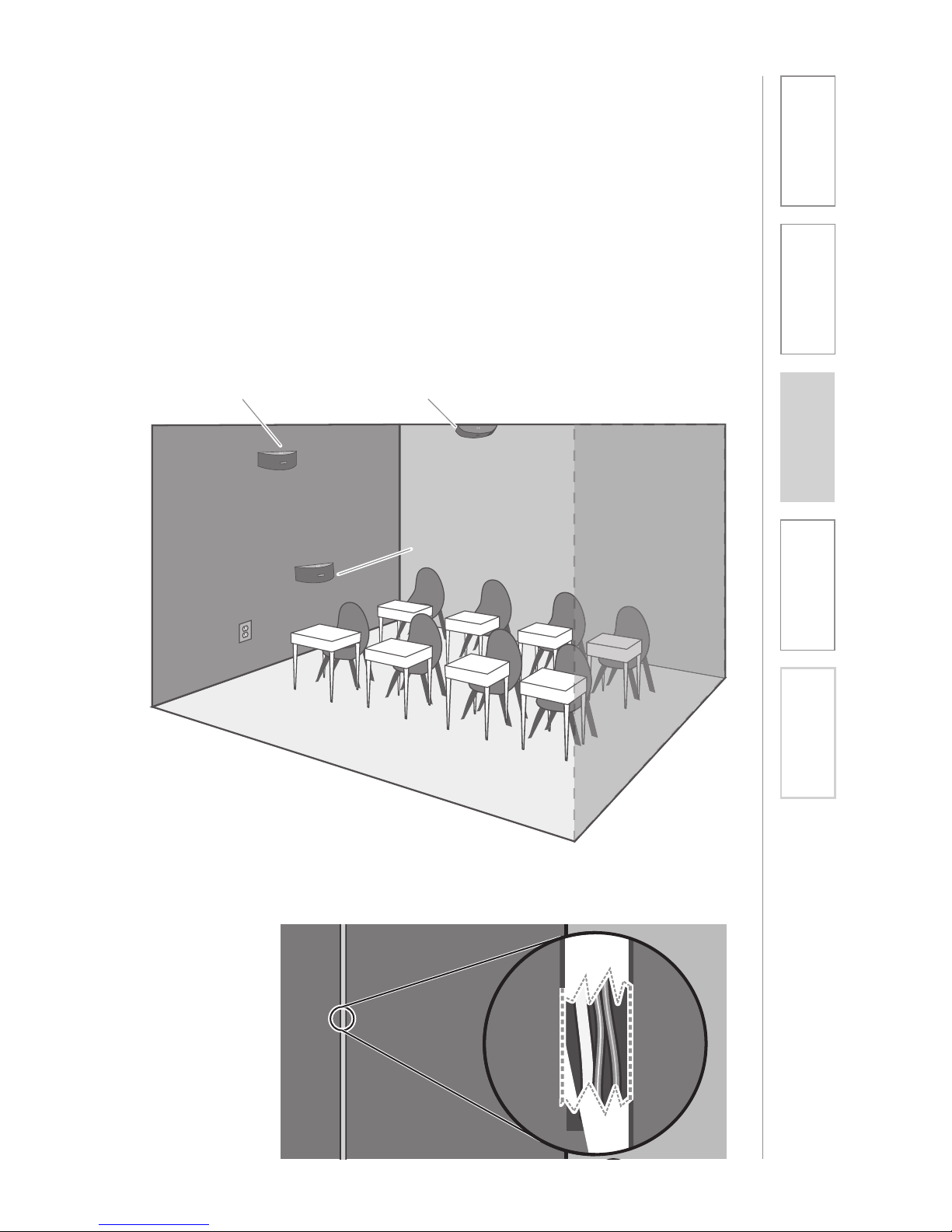
OPTIONAL: IR SENSOR/RECEIVER (ISR)
INSTALLATION
Sometimes having the Integrated Sensor Receiver (ISR) mounted on the TOPCAT
in the center of the room is not the ideal location. A poor location will cause
substandard performance of the Classroom Audio System. The ISR should be as
high as possible in the room – the ceiling is the best location, centered along the
longest wall in the room. When possible, use a conduit to protect the wires (not
included). Poor choices for placement are corners, on walls at heights lower than
7 feet (2 meters), or in places where the line of sight from the ISR to the receiver
is or could be obstructed.
Good placement
Conduit is Recommended
Best placement
Avoid!
Page 34
34
1. Overview 2. Installation
3. Optional
Accessories
4. Troubleshooting
5. Warranty, Safety
& Specifications
IR SENSOR/RECEIVER (ISR) INSTALLATION
CONT’D
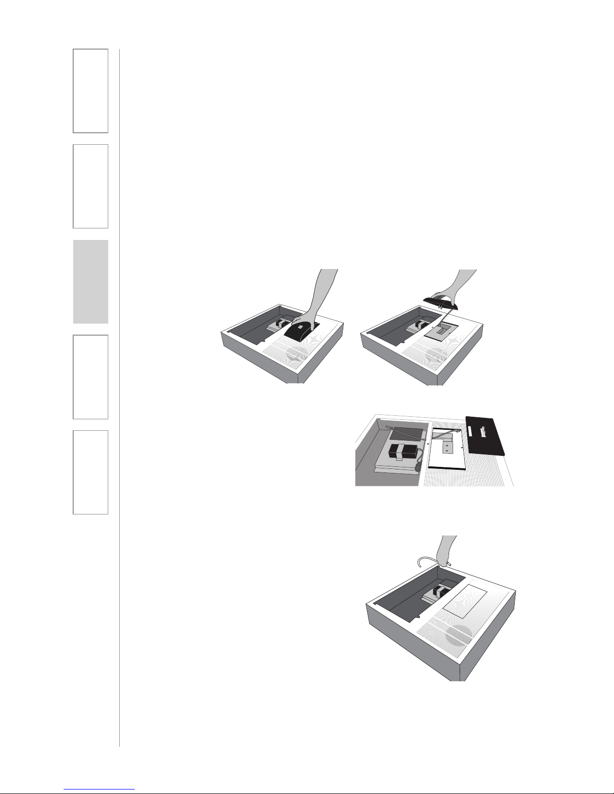
ISR Removal from TOPCAT
The system ISR is shipped mounted to the TOPCAT front panel. For most
installations, it will not need to be moved. However, there are some room
situations where the center of the classroom is not the best location and needs to
be removed from the TOPCAT and installed else where in the classroom.
1. Remove the ISR
Grasp the ISR on its two sides
and pull.
Sometimes
the ISR
cover will
come off
before its
body comes
loose. In this
case pull the
ISR’s body
until it comes loose.
2. Remove Cable
Disconnect the CAT-5e cable
connected to the ISR.
Page 35
35
2. Installation
3. Optional
Accessories
1. Overview 4. Troubleshooting
5. Warranty, Safety
& Specifications
IR SENSOR/RECEIVER (ISR) INSTALLATION
CONT’D
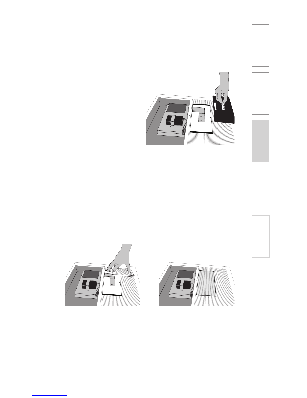
4. Place Cover Plate Over ISR
Opening
Install the blank cover plate (provided
with the TOPCAT) by snapping into
place where the ISR was located.
3. Remove Pin From ISR
Turn the ISR over and remove the ISR
Clip from the ISR (release the spring
latch and slide it out).
Page 36
36
1. Overview 2. Installation
3. Optional
Accessories
4. Troubleshooting
5. Warranty, Safety
& Specifications
IR SENSOR/RECEIVER (ISR) INSTALLATION
CONT’D
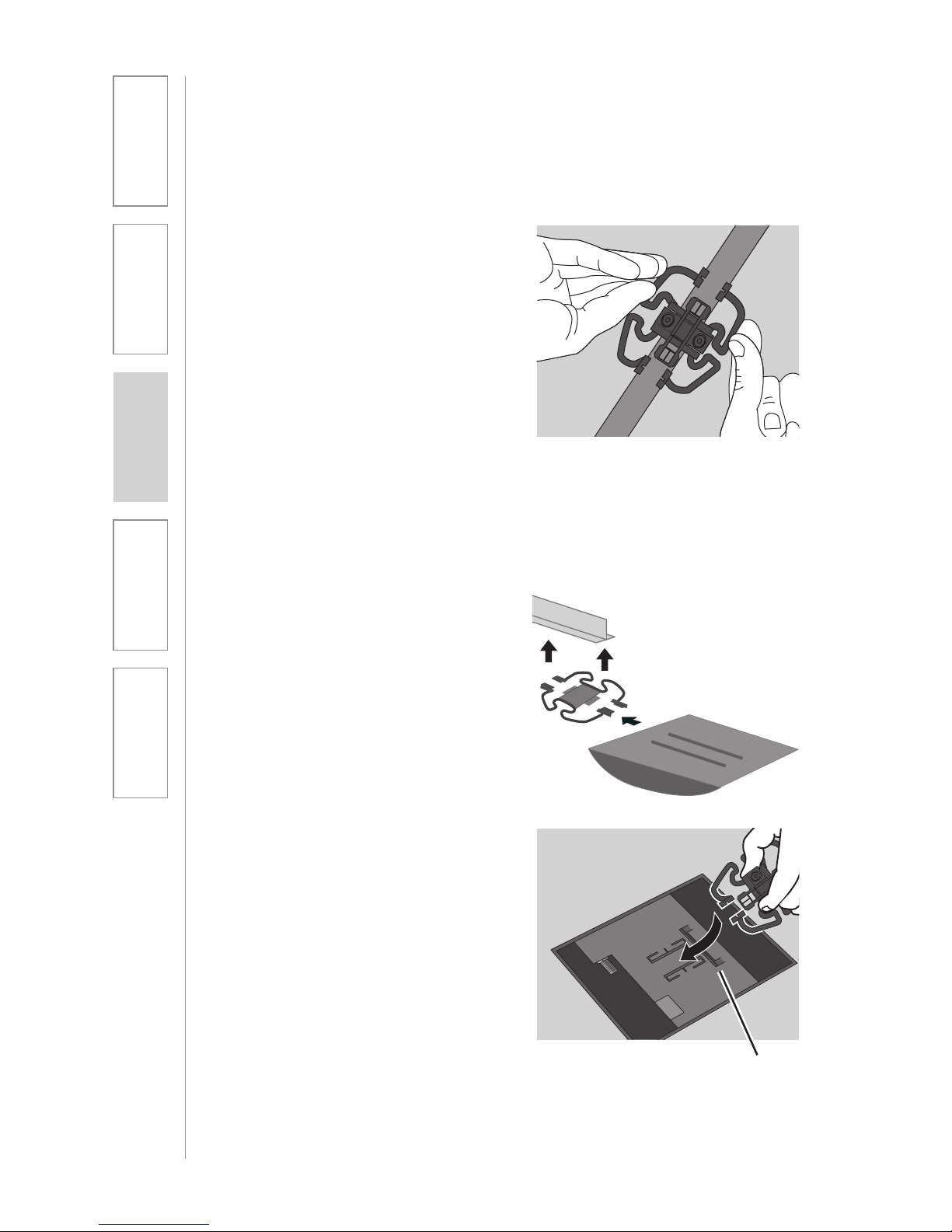
1. Attach the bracket to the ceiling
tile grid (t-bar).
a. Slide the tabs onto the outsides
of the t-bar, starting with one
corner.
b. Attach the second tab around
the other side of the t-bar.
c. Repeat with the other side of
the bracket so it is connected
at all four points.
2. Slide the ISR onto the bracket until
it “clicks” into place.
a. Guide the mounting rails
onto the bracket, oriented as
pictured.
b. Once secure the ISR locks into
place.
c. To remove the ISR, press the
release bar down and slide the
ISR off the bracket.
Suspended Ceiling Mount
clip connects to t-bar on ceiling
Release Bar
Page 37
37
2. Installation
3. Optional
Accessories
1. Overview 4. Troubleshooting
5. Warranty, Safety
& Specifications
IR SENSOR/RECEIVER (ISR) INSTALLATION
CONT’D
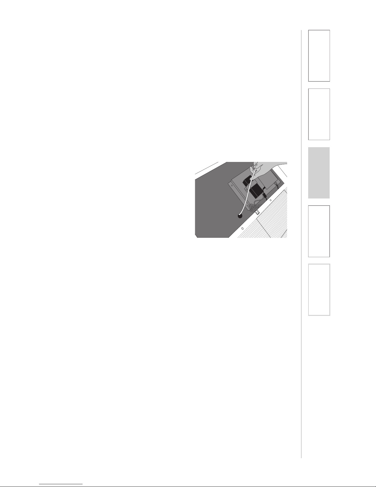
3. Uncoil the Cat 5 sensor cable.
Connect one end of the cable
to the ISR. Secure wire overhead
and route it back to the TOPCAT
system, making sure to follow all
local codes.
4. Insert the CAT 5 cable into the
TOPCAT chassis through the 1
inch diameter hole provided.
5. Open the TOPCAT front panel
door. Find where the previous CAT
5 cable was connected and plug
in the new CAT 5 cable.
6. Secure the CAT 5 cable using
cable ties such that the cable is
not touching the chassis or able to
vibrate against the speaker panel.
7. Close the TOPCAT access door.
Once you find a suitable location for the ISR, follow these instructions to mount
it. There are different instructions for mounting depending on if the ISR will be
mounted to a suspended ceiling grid or secured to a wall / solid vertical surface.
Page 38
38
1. Overview 2. Installation
3. Optional
Accessories
4. Troubleshooting
5. Warranty, Safety
& Specifications
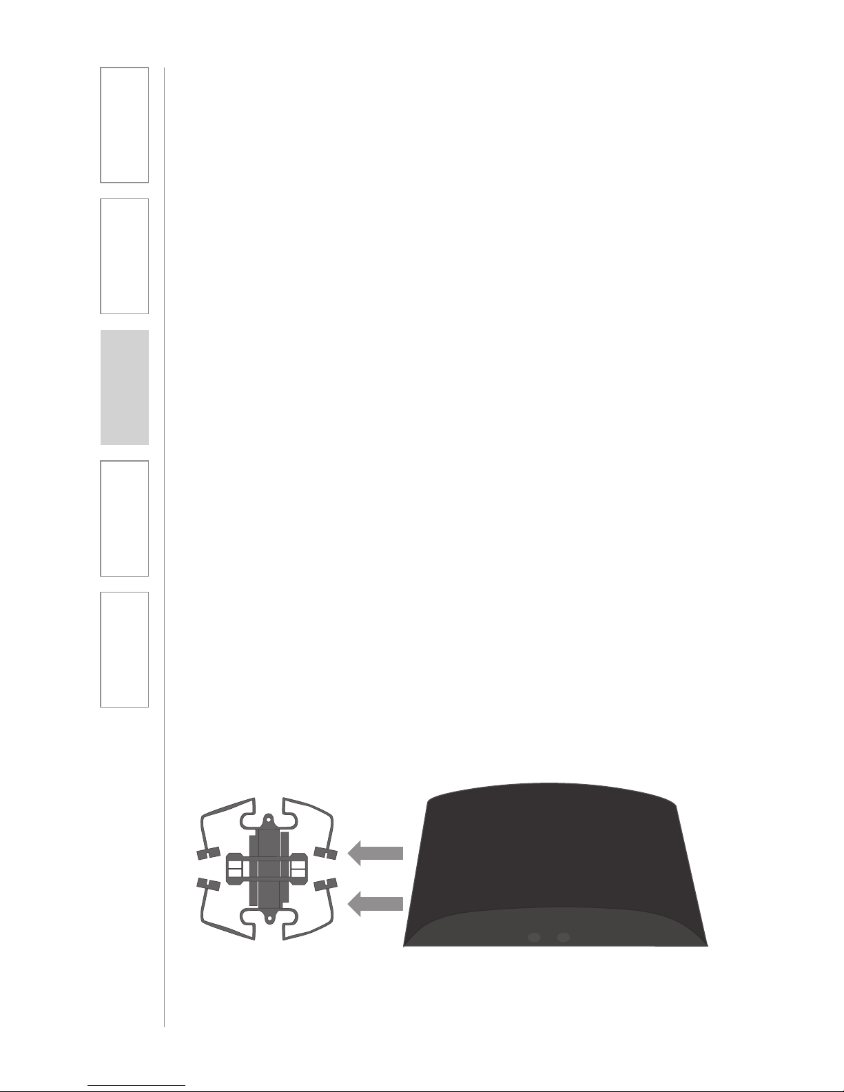
1. Screw the bracket to a place high
on the wall or in the middle of the
solid ceiling. Mount the bracket
horizontally as shown above.
2. Uncoil the Cat 5 sensor cable.
Connect one end of the cable to
the ISR. Route the wire back to the
TOPCAT system, securing it along
with way using surface raceway
where possible.
3. Slide the ISR onto the bracket until
it “clicks” into place.
a. Guide the mounting rails
onto the bracket, oriented as
pictured.
b. Once secure, the ISR locks into
place.
c. To remove the ISR, slide a
ruler or screwdriver behind the
ISR to press the release bar
down and slide the ISR off the
bracket
4. Remove the metal cover (move
over to cover the other hole
or discard if electrical power is
installed) over the 1 inch dia. round
hole of the TOPCAT back can to
pass the cable into the TOPCAT.
IR SENSOR/RECEIVER (ISR) INSTALLATION
CONT’D
Wall/Solid Ceiling Mount
5. Open the TOPCAT front panel
door. Find where the previous
CAT 5 cable was connected and
plug in the new CAT 5 cable.
6. Secure the CAT 5 cable using
cable ties such that the cable is
not touching the chassis or able
to vibrate against the sides of the
unit.
7. Close the TOPCAT access door.
Page 39
39
1. Overview 2. Installation
3. Optional
Accessories
4. Troubleshooting
5. Warranty, Safety
& Specifications
TOOLS REQUIRED
• Flat blade screw driver
• Phillips screw driver
REMOVE AND REPLACE THE
AMPLIFIER MODULE
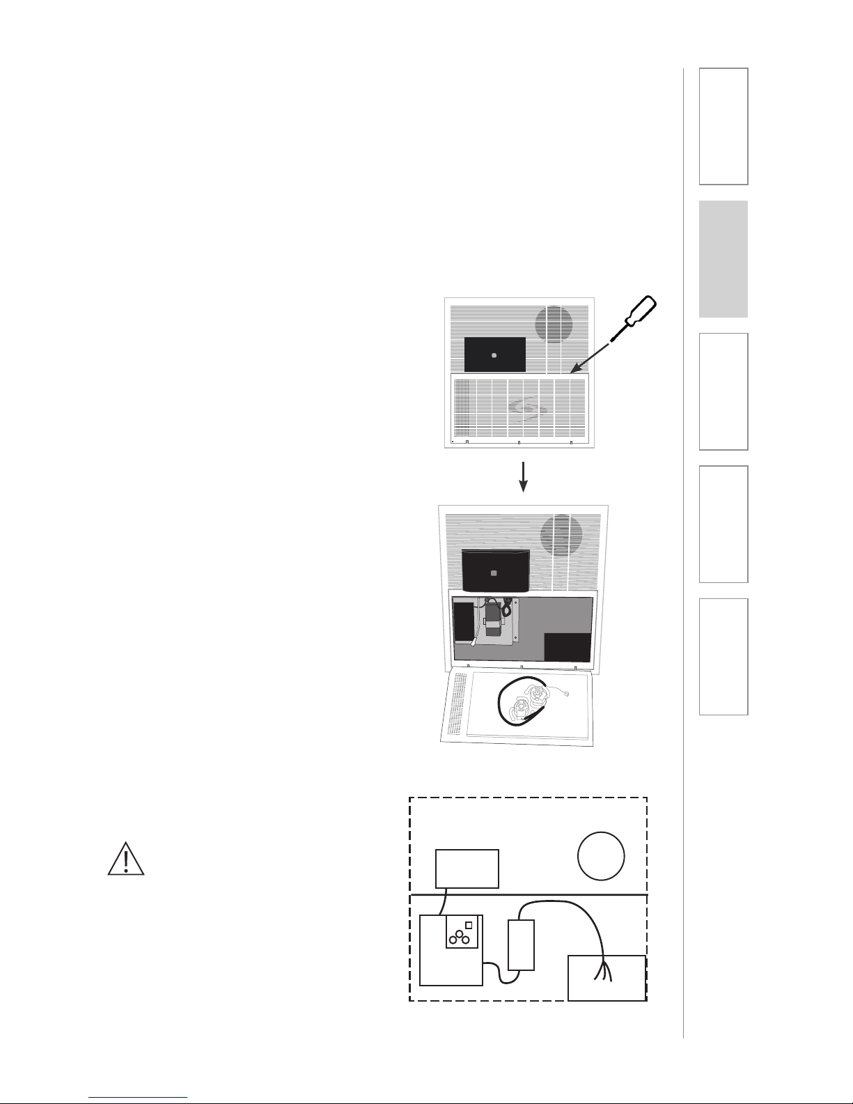
1. Open the TOPCAT access door
by inserting flat head screwdriver
into the slot tab on the door.
2. Unplug the power cable from the
power supply located inside the
TOPCAT chassis.
WARNING!
TOPCAT System uses standard 100 –
240VAC power. Obtain the services of
a certified electrician when supplying,
connecting and disconnecting power
to the TOPCAT chassis. Be sure
electrical installation complies with
local building codes. Improperly
installing and /or connecting power
may result in Equipment Damage,
serious injury and/or Death.
Troubleshooting TOPCAT may require the amplifier module to be replaced.
Troubleshooting and repair can be accomplished without requiring the service
of an electrician as long as the TOPCAT chassis is not removed from the
ceiling. Once replaced, the amplifier will need to be registered with the Media
Connector Module and the microphone channel A and channel B will need to be
setup with the classroom microphone(s). Use the following procedures to remove
and replace the amplifier module:
REMOVE AND REPLACE AMPLIFIER
MODULE
Integrated
Sensor/
Receiver
Power
Supply
Amplier/
TX/RX
TOPCAT Module
Page 40
40
1. Overview 2. Installation
3. Optional
Accessories
4. Troubleshooting
5. Warranty, Safety
& Specifications
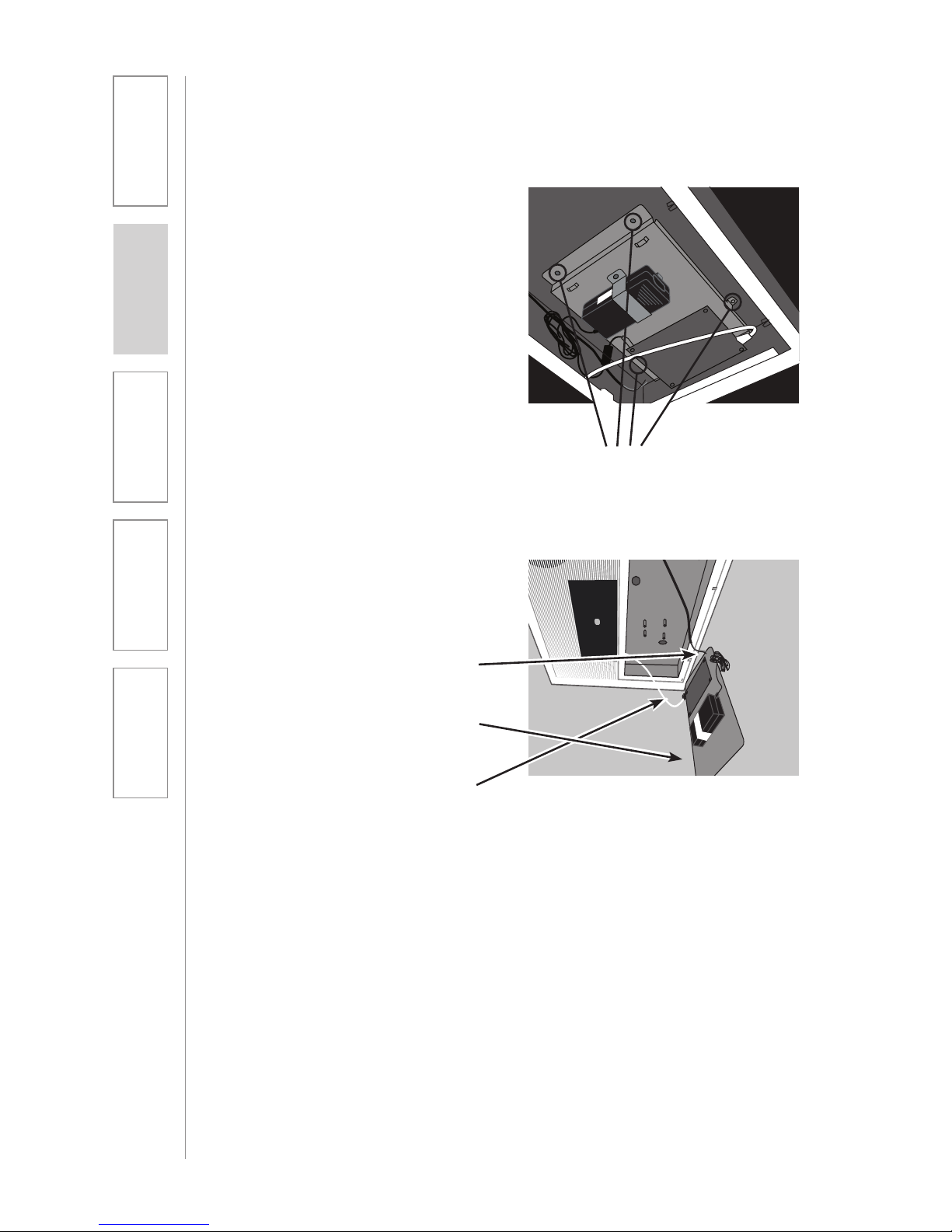
3. Loosen the screws holding the
Amplifier to the chassis. See
Figure
4. Unplug the following cables from
the amplifier module
REMOVAL AND REPLACE AMPLIFIER
MODULE CONT’D
a. Cone Speaker
b. Flat panel speaker
c. ISR Cat 5 cable
Remove Screws
Page 41
41
1. Overview 2. Installation
3. Optional
Accessories
4. Troubleshooting
5. Warranty, Safety
& Specifications
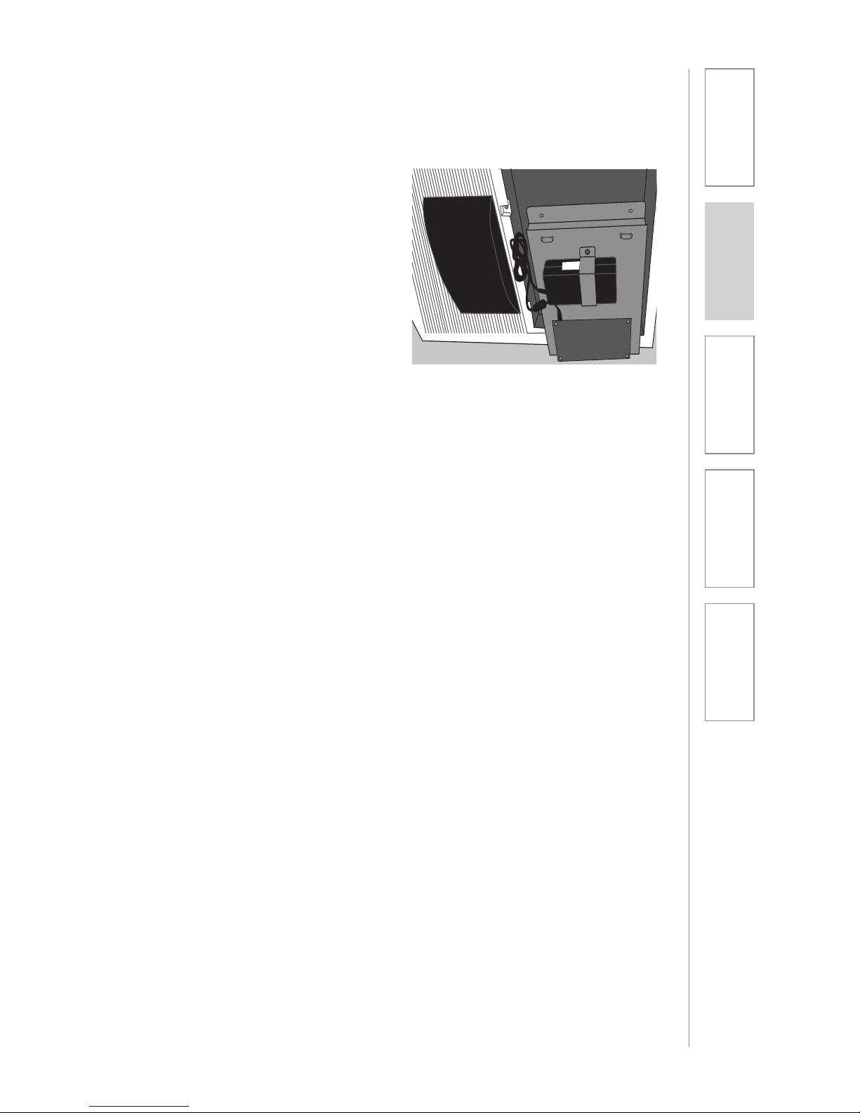
5. Remove the Amplifier module
6. To install the new amplifier
module, perform this procedure
in reverse order.
7. Registering the TOPCAT
with the Media Connector
Module perform the TOPCAT
AND MEDIA CONNECTOR
REGISTRATION procedure in
this manual.
8. To adjust the optimum
microphone volume level,
perform the SETUP AND
OPERATION OF THE REDMIKE
VC procedure in this manual
REMOVAL AND REPLACE AMPLIFIER
MODULE CONT’D
Page 42

42
1. Overview 2. Installation
3. Optional
Accessories
4. Troubleshooting
5. Warranty, Safety
& Specifications
ALL PROBLEMS: Most Problems are
related to low battery power.
SOLUTION: Battery Check
• ConrmthePowerLEDisblue.
• Conrmbatteriesarecharged
each night.
• Conrmproperbatteriesare
used. The REDMIKE VC requires
the Lightspeed BA-NH2A27
rechargeable sensing battery for
proper charging. The REDMIKE
Share uses the BA-NH2APK
rechargeable battery pack.
•Makesurethemicrophonesare
turned off while charging so a full
charge is attained. Full charge will
last eight hours.
• Inspectthebatterycontacts.Clean
and adjust if necessary.
PROBLEM: Hearing Static
SOLUTION: Follow these steps to
eliminate static.
• Ensuresensorisinoptimum
location (refer to sensor placement
in manual). A single sensor will
cover a 1600 sq. ft. enclosed
classroom.
• EnsurethatnootherREDMIKE
VC/REDMIKE Share is operating
on the same channel. Check the
channel switch setting on the
back of the REDMIKE VC or in
the battery compartment of the
REDMIKE Share.
PROBLEM: Low Volume or Feedback
SOLUTION: Follow these steps to
eliminate low volume or feedback.
• Ensuremicrophoneispositioned
appropriately, just below the collar
bone.
• Checkvolumelevelonthe
REDMIKE VC. If the volume is too
high, feedback will occur. Adjust
accordingly.
PROBLEM: No Sound From Speaker
SOLUTION: Follow these steps to
produce sound from speakers.
• TurntheMediaConnectoron.
Confirm that the POWER light
located on the top panel switch
is on.
• Conrmsignalisbeingreceived
at the ISR on the TOPCAT. The IR
signal light will be RED (Green for
CH B) indicating a signal is being
received.
• ConrmthatREDMIKEVCis
turned on. There will be a BLUE
LED on the microphone to indicate
it is powered on.
Note: Most problems are directly related to low battery power. Please run
through the “Battery Check” items first. For remaining troubleshooting, use
known good, fully-charged batteries.
If you review these instructions and still have questions, write down the
serial number and model number of your system and call Lightspeed
Technical Services at 800.732.8999, 5 a.m. – 5 p.m., PST.
SECTION 4:
TROUBLESHOOTING
COMMON PROBLEMS AND SOLUTIONS
Page 43

43
1. Overview 2. Installation
3. Optional
Accessories
4. Troubleshooting
5. Warranty, Safety
& Specifications
FIVE-YEAR LIMITED WARRANTY
Our Service Department (800.732.8999, 5 a.m. – 5 p.m., PST) will handle all your
repair/replacement needs.
SECTION 5:
WARRANTY, SAFETY &
SPECIFICATIONS
Lightspeed Classroom Audio Systems are guaranteed against malfunction due to
defects in materials and workmanship for a period of FIVE (5) YEARS, beginning
at the date of the purchase invoice. If such malfunction occurs, the product
will be repaired or replaced (at Lightspeed’s option) without charge during the
warranty period.
Lightspeed’s Warranty Exchange Program applies to all infrared systems within
the five (5) year warranty period. If an infrared product or component has an issue
that requires service, a refurbished replacement will immediately be sent to the
customer to minimize downtime. Customers will receive the exchange product(s)
or component(s) within 2-3 days. A prepaid return label will be included with
exchanged products so original malfunctioned equipment can be returned to
Lightspeed. Any exchanged equipment will remain covered under the original
five (5) year warranty.
1. Warranty on infrared microphones is FIVE (5) YEARS.
2. Warranty on Lightspeed NiMH rechargeable batteries is one (1) year.
3. Prepaid shipping label provided by Lightspeed for warranty repairs within the
U.S. Customers outside the U.S. should refer to the Lightspeed website (www.
lightspeed-tek.com) for warranty repair instructions.
4. Warranty does not extend to finish, appearance items, or malfunctions due
to abuse or operation other than specified conditions, nor does it extend
to incidental or consequential damages. Repair by other than Lightspeed
or its authorized service agencies will void this guarantee. Information on
authorized service agencies is available from Lightspeed Technologies, Inc.
Page 44
44
1. Overview 2. Installation
3. Optional
Accessories
4. Troubleshooting
5. Warranty, Safety
& Specifications
CERTIFICATIONS
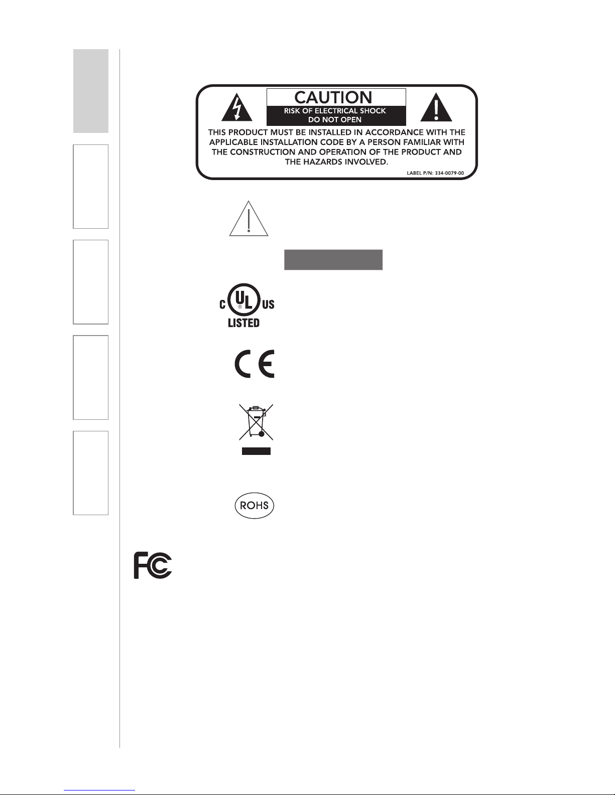
This product conforms with the essential
requirements of the following European Union
Directives: 89/336/EEC, 92/31/EEC, 93/68/
EED, and 2004/108/EC Electromagnetic
Compatibility Directives.
USE A LIGHTSPEED
SUPPLIED BATTERY ONLY
Lightspeed Technologies launched a formal
product recycle program in Europe that
complies with the European Union Directive
2002/96/EC on Waste Electrical and Electronic
Equipment (“WEEE Directive”). Please visit our
website at www.Lightspeed-tek.com for more
information.
This product is manufactured using lead-free
processes and is free of other materials
harmful to the environment. It conforms to the
most stringent new European guidelines for
consumer products (RoHS).
This product is listed to UL standards
and requirements for electrical safety by
Underwriters Laboratories Inc.
This device complie s with part 15 of the FCC Rules. Operation is subject to the following two conditions: (1) This device
may not cause harmful inter ference, and (2) this device must accept any interference received, including interference that
may cause undesired operation.
Chang es or modifications not expressly approved by the part y responsible for compliance could void the user’s authority
to operate this equipment.
This equipment has been tes ted and found to comply with the limits of a Class B Digital Device, pursuant to Par t 15 of
the FCC Rules. Th ese limits are designed to provide reasonable protection again st harmful interference in a resid ential
installation.
This equipment generate s, uses and can r adiate radio frequency en ergy an d, if not installed and u sed in ac cordance wit h
the instruction may cause harmful interference to r adio co mmunication. However, there is no guarantee that inter ference
will not occur in a part icular installation.
However, there is no guara ntee that inter ference will not occur in a particular installation. If this equipment does cause
inter ference to radio or television rece ption, which c an be determin ed by tur ning the equipment off and on, the us er is
encouraged to try to correct the inter ference by one or more of the following measures.
!
Caution: To maintain the compliance wit h the FCC’s RF exposure guideline, place Media Connector & TOPCAT at least
20 cm from near by persons.
• Reorient or relocate the receiving a ntenna
• Increase the separation between the eq uipment and the recei ver
• Connect th e equipment in to an outlet on a circuit diffe rent from that to w hich the recei ver is connec ted
• Consult the dealer or an experienced radio/T V technician for help
SAFETY WARNINGS AND CERTIFICATIONS
Page 45

45
1. Overview 2. Installation
3. Optional
Accessories
4. Troubleshooting
5. Warranty, Safety
& Specifications
OVERALL SPECIFICATIONS
TOPCAT Specifications
Descriptiont Two-way hybrid speaker system with NXT
distributed mode panel and low frequency
cone driver
Panel Size 16.25” x 8.25”
Frequency Response 60 Hz - 18 kHz @ 10dB
Impedance 4 Ohms
Power Handling 20W RMS
Power 24V DC 2.5A
Enclosure 24” x 24” x 3” plenum-rated enclosure (UL
2043) / 595mm x 595mm x 101.6mm
Weight 22 lbs / 9.98 Kg
RECEIVER/TRANSMITTER SPECIFICATIONS
Media Connector Module
Frequency Response 80 Hz to 10 kHz ±3 dB
Signal-to-noise Ratio >70 dB
Audio Distortion <1%
Audio Inputs Four (4) 3.5mm stereo jack
Audio Outputs One 3.5mm stereo jack with volume control
DC Power Input 5 V / 1.0 Amp, 0.65mm coaxial barrel DC
power jack
USB Power 5 V mini-B USB connector
Mounting wall or table-top
Dimensions (L x W x H) 5.75” x 8.75” x 10” / 146mm x 222.3 x
254mm
TRANSMITTER SPECIFICATIONS
REDMIKE VC
Audio Distortion < 1 %
Built-in Microphone Unidirectional Electret
Battery Power (1-year warranty) 1 AA NiMH Rechargeable
Sensing Battery
Audio Input 3.5 mm
Dimensions (W x D x H) 0.9” x 1.0” x 3.5” / 22.86mm x 25.4mm x 88.9mm
Weight 2.1 oz. / 59.53 g
REDMIKE Share Handheld Microphone
Audio Distortion < 1 %
Built-in Microphone Unidirectional Electret
Battery Power (1-year warranty) 2 AA NiMH Battery Pack Rechargeable
Dimensions (W x D x H) 2.25” x 2.25” x 8.75”/ 57.5mm x 57.15mm x
222.25mm
Weight 7.36 oz. / 208.65 g
SYSTEM SPECIFICATIONS
Page 46

46
1. Overview 2. Installation
3. Optional
Accessories
4. Troubleshooting
5. Warranty, Safety
& Specifications
INFRARED SENSOR
INTEGRATED SENSOR / RECEIVER (ISR)
Power From TOPCAT
Reception Coverage Rooms up to 1600 sq ft / 150 m2 (ceiling 12ft
/ 3.66 or less)
Mounting Integrated on TOPCAT ceiling clip / wall
bracket
Receiving Diodes 32
SYSTEM SPECIFICATIONS CONT’D
Page 47

Page 48

Page 49

Page 50
50
1. Overview 2. Installation
3. Optional
Accessories
4. Troubleshooting
5. Warranty, Safety
& Specifications
Installer’s Manual
TOPCAT
Page 51

51
1. Overview 2. Installation
3. Optional
Accessories
4. Troubleshooting
5. Warranty, Safety
& Specifications
IMPORTANT SAFETY INSTRUCTIONS
1. Read these instructions.
2. Keep these instructions.
3. Heed all warnings.
4. Follow all instructions.
5. Do not use the apparatus near
water.
6. Clean only with dry cloth.
7. Do not block any ventilation
openings. Install in accordance
with the manufacturer’s
instructions.
8. Do not install near any heat
sources such as radiators,
heat registers, stoves, or
other apparatus (including
amplifiers) that produce heat.
9. Do not defeat the safety
purpose of the polarized
or grounding-type plug.
A polarized plug has two
blades with one wider than
the other. A grounding- type
plug has two blades and a
third grounding prong. The
wide blade or the third prong
is provided for your safety. If
the provided plug does not
fit into your outlet, consult an
electrician for replacement of
the obsolete outlet.
10. Protect the power cord
from being walked on or
pinched particularly at plugs,
convenience receptacles, and
the point where they exit from
the apparatus.
11. Only use attachments/
accessories specified by the
manufacturer.
12. Use only with a cart, stand,
tripod, bracket or table
specified by the manufacturer,
or sold with the apparatus.
When a cart is used, use
caution when moving the cart/
apparatus combination to
avoid injury from tip-over.
13. Unplug this apparatus during
lightning storms or when
unused for long periods of
time.
14. Refer all servicing to qualified
service personnel. Servicing is
required when the apparatus
has been damaged in any way,
such as power-supply cord or
plug is damaged, liquid has
been spilled or objects have
fallen into the apparatus, the
apparatus has been exposed
to rain or moisture, does not
operate normally, or has been
dropped.
15. When the mains plug or
appliance coupler used as
the disconnect device, it shall
remain readily operable.
16. Please keep the unit in a good
ventilation environment.
Page 52
52
1. Overview 2. Installation
3. Optional
Accessories
4. Troubleshooting
5. Warranty, Safety
& Specifications
IMPORTANT SAFETY INSTRUCTIONS CONT’D
To avoid potential equipment damage and/or serious injury, READ AND
FOLLOW all safety precautions when installing the TOPCAT. WARNINGS are
coated throughout the procedural steps in this guide, and are repeated below
for emphasis.
CAUTION
• USE A CERTIFIED ELECTRICIAN FOR POWER CONNECTIONS. The
TOPCAT system uses standard 100 – 240VAC power. Obtain the services of
a certified electrician when supplying and connecting power to the Ceiling
Enclosure. BE SURE electrical installation complies with local building
codes. Improperly installing and/or connecting power to the system may
result in EQUIPMENT DAMAGE, serious INJURY and/or DEATH.
• DO NOT INSTALL ALONE. The Ceiling Enclosure weighs approximately 20
lbs, and requires at least two people to install. DO NOT install alone.
• USE SUITABLE LADDERS. use proper ladders or support platforms when
installing the TOPCAT Enclosure. DO NOT stand on chairs, tables, or other
unsuitable surfaces.
• SUPPORT THE CEILING ENCLOSURE PROPERLY. DO NOT allow the
full weight of the Ceiling Enclosure to rest on the tile grid of the ceiling.
The Ceiling Enclosure is designed to be suspended at TWO POINTS by
suspension wires (secured to rafters or other suitable mounting points) and
to rest LIGHTLY on the tile grid.
Page 53
53
1. Overview 2. Installation
3. Optional
Accessories
4. Troubleshooting
5. Warranty, Safety
& Specifications
SYSTEM COMPONENTS AND UNPACKING
The standard configuration of the TOPCAT® will contain:
Charging Cradle and
Power Supply
REDMIKE® VC
Volume Control
Microphone
TOPCAT Module
Media Connector
Module
SECTION 1:
OVERVIEW
Page 54
54
1. Overview 2. Installation
3. Optional
Accessories
4. Troubleshooting
5. Warranty, Safety
& Specifications
SYSTEM COMPONENTS AND UNPACKING
CONT’D
Audio Cable Kit
USB Cable
Screws and Anchors
for optional wall
mounting
OPTIONAL COMPONENTS
Optional equipment which may be part of your TOPCAT system:
REDMIKE® Share
Handheld Mic &
Charger Cable
DC Cable
Page 55

55
1. Overview 2. Installation
3. Optional
Accessories
4. Troubleshooting
5. Warranty, Safety
& Specifications
Standard Accessories
TRX-TC TOPCAT all-in-one ceiling mount system
PS-24V-2.5 24V/2.5A power supply for TOPCAT
RMV REDMIKE VC microphone with battery
BA-NH2A27 AA NiMH rechargeable sensing battery for REDMIKE
AC-RMLC2 REDMIKE lavaliere cord
BC-RMCC REDMIKE cradle charger
PS-5V-1.0 5V/1.0A power supply
TRX-MC Transmitter-Receiver Media Connector Module
CA-USBAM USB cable (type A-MINI-B)
CA-MSC3535 Patch cables 3.5mm to 3.5mm short length
CA-AD-RCA2-35 Dual RCA jack – 3.5mm stereo plug adapter
Optional Components
RMS REDMIKE Share handheld microphone w/battery pack
MC-TK250LTM Noise-canceling headset microphone
AC-TCC7 Charging cable for LT-71 and REDMIKE Share
microphones
CA-RCA6 6’ dual RCA audio cable
CA-RCA24 24’ dual RCA audio cable
CA-MMC2535 Audio patch cable (2.5 mm mono to 3.5 mm mono)
BA-NH2APK AA Rechargeable battery (REDMIKE Share)
DCPEX-NA 50’ plenum rated DC Power cable kit
SYSTEM COMPONENTS
Equipment which may be part of your TOPCAT:
Page 56
56
1. Overview 2. Installation
3. Optional
Accessories
4. Troubleshooting
5. Warranty, Safety
& Specifications
INSTALLATION PLANNING
SECTION 2:
INSTALLATION
Before beginning installation, make sure you have the necessary tools
and materials on hand and that pre-installation site preparation has been
accomplished.
TOOLS & MATERIALS
In addition to the contents of the
TOPCAT system, you will need the
following tools & materials:
• Flat Blade screwdriver (small)
• Pliers
• Wire cutters
• Drill
• Utility Knife
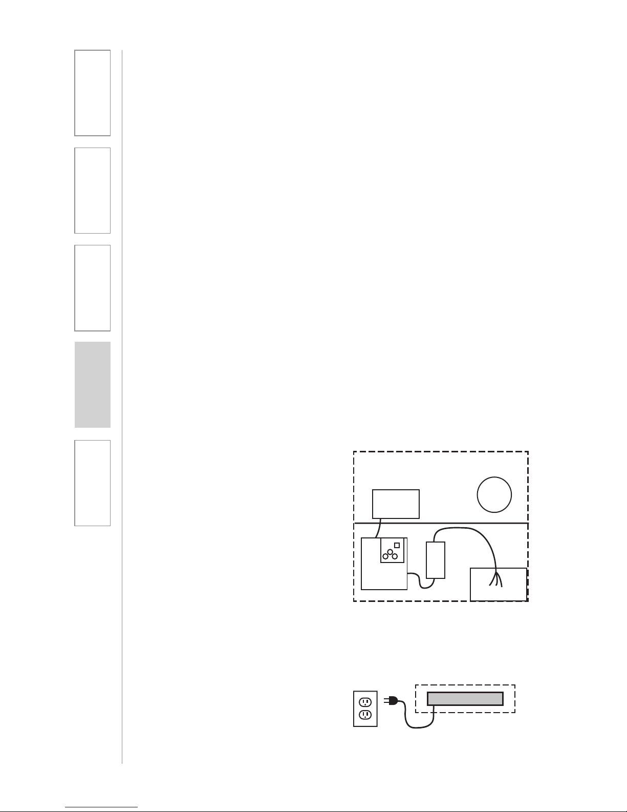
SITE PREPARATIONS
A schematic/wiring diagram of a
typical TOPCAT installation is shown
in the following figure:
NOTE: TOPCAT is designed for
installation in a 2’ x 2’ or 2’ x 4’
suspended ceiling grid (or 600mm x
600mm international ceiling grids). If
you do not have this type of ceiling,
please contact your local Lightspeed
Classroom Audio Consultant.
Audio Mixer/TX/RX
Media Connector Module
Integrated
Sensor/
Receiver
Power
Supply
Amplier/
TX/RX
TOPCAT Module
Page 57
57
1. Overview 2. Installation
3. Optional
Accessories
4. Troubleshooting
5. Warranty, Safety
& Specifications
The TOPCAT is shipped ready to mount in a standard suspended ceiling grid. All
mounting hardware need to secure the TOPCAT in the ceiling is provided except
for that needed to wire the AC power to the chassis.
TOPCAT will distribute sound throughout a classroom of up to 1600 square feet.
The location of TOPCAT is critical to ensure even sound distribution.
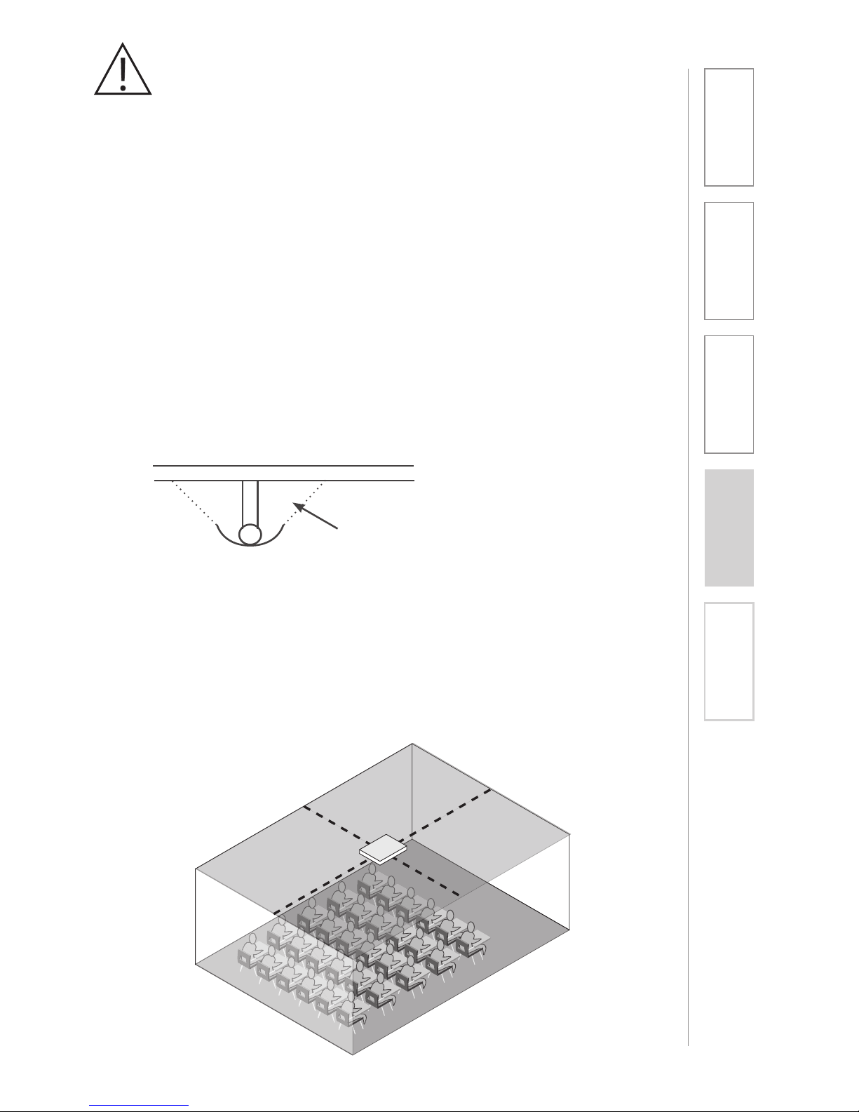
1. Identify the center of the listening area of the classroom for optimum location.
See Figure 1.
2. Select a ceiling tile that is free of fixtures (lighting, HVAC, etc.) nearest to the
center point.
3. Remove the selected ceiling tile for TOPCAT installation.
NOTE: Do not install where the integrated sensor/receiver (ISR) is in the
reflected light of a hanging light fixture. The ISR can be removed from the
TOPCAT and placed elsewhere on the ceiling or classroom wall.
1. SELECT MOUNTING LOCATION
Fig 1: Identify the Center of the Listening Area
Page 58
58
1. Overview 2. Installation
3. Optional
Accessories
4. Troubleshooting
5. Warranty, Safety
& Specifications
The dimensions of the TOPCAT speaker are 595mm x 595mm and is designed
to lie onto any standard suspended ceiling tile grid. Spacers are attached to
center the TOPCAT in a 2’ x 2’ or 2’ x 4’ ceiling grid. (Remove these spacers when
installing into a 600 x 600 mm grid.)
1. If the ceiling tile that was removed is 2’ x 4’, it needs to be cut in half to
accommodate the TOPCAT. If the ceiling tile that was removed is 2’ x 2’, no
cutting of the tile is necessary.
2. Set the ceiling tile on a flat work surface with the patterned side facing down.
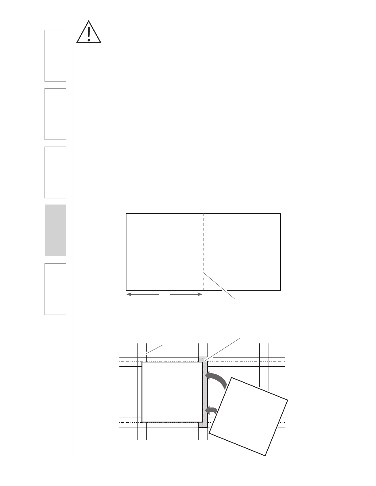
3. Using a straight edge, cut the 2’ x 4’ ceiling in half (see figure 2) leaving two 2’
x 2’ sections.
4. Locate the 2’ ceiling grid t-bar attachment. Locate the attachment slots in
the existing ceiling grid and snap the new t-bar into place to crate two 2’ x 2’
openings (see figure 3).
5. Lift the TOPCAT up and lay it into the desired 2’ x 2’ opening in the ceiling.
2. INSTALLING THE TOPCAT INTO THE
CEILING GRID
Figure 2: Cut the 2’ x 4’ Tile in Half
Throw Away Remaining Ceiling Tile
Cut with straight
edge
24”
Figure 3: Create Two 2’ x 2’ Openings
New T-Bar
Existing
Tile Grid
TOPCAT
H
alf
T
ile
Page 59
59
1. Overview 2. Installation
3. Optional
Accessories
4. Troubleshooting
5. Warranty, Safety
& Specifications
3. SECURING THE TOPCAT
To comply with Building Codes, the TOPCAT MUST be fastened to the ceiling
grid and secured with a safety wire. Follow all local and state laws.
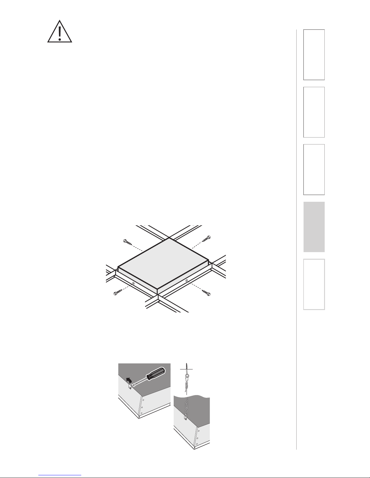
1. Locate the four (4) self-drilling sheet metal screws.
2. Utilizing existing center holes on the vertical section of the ceiling grid, drill
one screw per side on opposite sides of the TOPCAT (see figure 4).
3. Locate the 15ft length of safety wire and the eye screw. The safety wire needs
to be permanently attached to the solid structural ceiling above.
4. Install the eye screw (or concrete anchors if necessary) into the structural
ceiling.
5. Loop one end of the safety wire through the eye screw (or anchor), then twist it
around itself at least five times.
6. Pull one of the tabs up on the TOPCAT rear panel (located in opposite corners)
and loop the other end of the safety wire through the tab. Pull the wire
through until it is taught and twist it around itself at least five times to secure
the speaker. Cut off any excess wire if needed. (see figure 5)
Figure 4: Secure with Self-Drill Screws into the TOPCAT
Figure 5: Looping the Safety Wire Through the Tab
Page 60
60
1. Overview 2. Installation
3. Optional
Accessories
4. Troubleshooting
5. Warranty, Safety
& Specifications
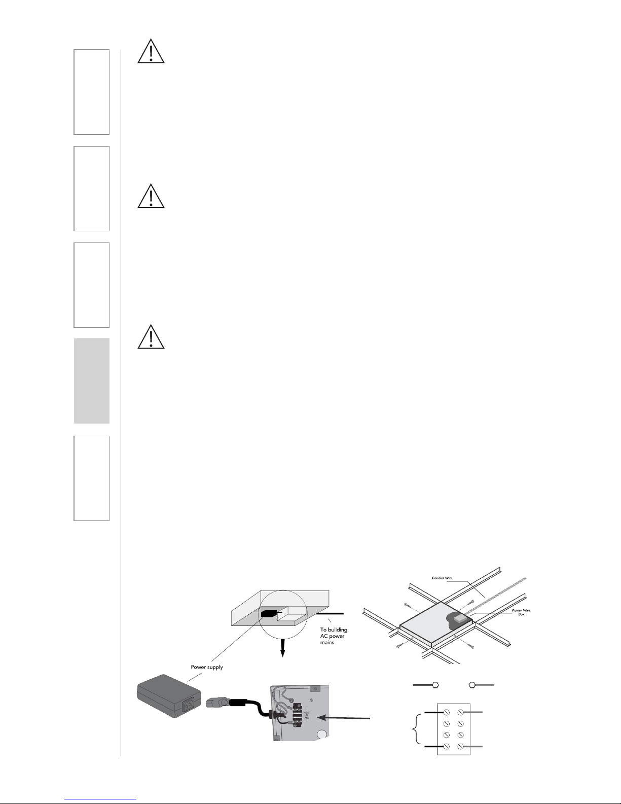
4. INSTALLING AND WIRING ELECTRICAL
POWER
There are two methods of providing power for the TOPCAT.
1. New Construction Installations: Connect directly to the buildings mains AC
power.
2. Retrofit situations: Can either wire to the building mains or order the optional
power extension cable (DCPEX-NA).
SUPPLY POWER TO THE SELECTED LOCATION
WARNING!
USE A CERTIFIED ELECTRICIAN FOR POWER CONNECTIONS.
The TOPCAT System uses standard 100 – 240VAC power. Obtain the services
of a certified electrician when supplying and connecting power to the TOPCAT
chassis. Be sure electrical installation complies with local building codes.
Improperly installing and /or connecting power to the system may result in
Equipment Damage, serious injury and/or Death.
When routing power to the TOPCAT, avoid interference with lighting and other
noise possibilities.
CAUTION:
These servicing instructions are for use by qualified service personnel only. To
reduce the risk of electric shock do not perform any servicing other than that
contained in the operating instructions unless you are qualified to do so.
Wire AC power to the TOPCAT as follows:
a. Turn off the current at the main breaker. Attach the electrical wiring to the
TOPCAT Ceiling Module as shown
b. Find the electrical box hole on the TOPCAT back can. Insert the mains
electrical wire through the hole.
c. Find and open the front panel door on the TOPCAT.
d. Remove the lid to the internal electrical box
e. Attach the ground wire to the grounding lug provided. Attach the remaining
two wires to the terminal block screws adjacent to the internal power wires.
f. Replace the lid on the electrical box and turn the electrical current on at the
main switch.
Green Green
Brown
Light Blue
TO
POWER
SUPPLY
100VAC
– 240VAC
Page 61
61
1. Overview 2. Installation
3. Optional
Accessories
4. Troubleshooting
5. Warranty, Safety
& Specifications
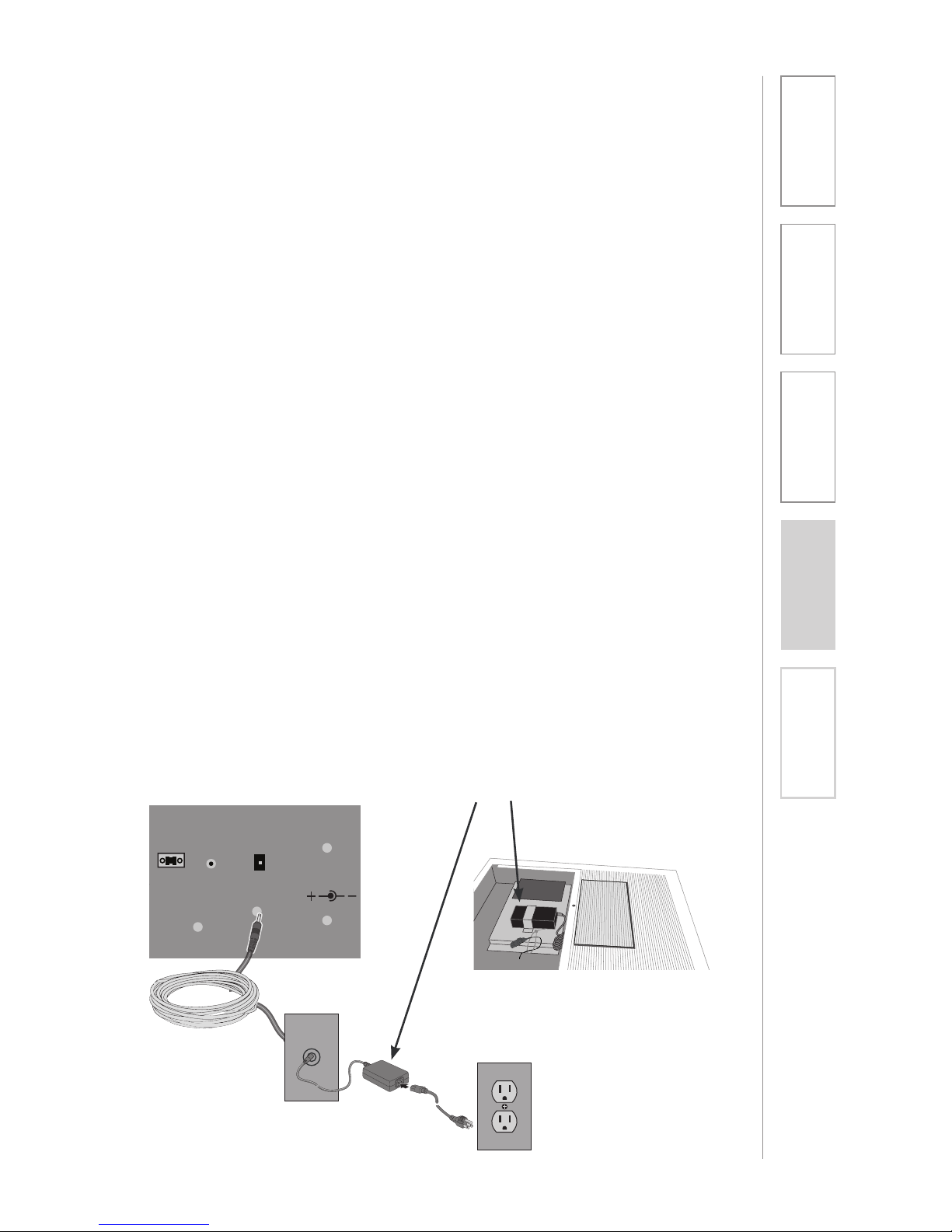
ALTERNATE POWER (OPTIONAL)
When electrical AC power is not available above the ceiling for installation
with the TOPCAT, there is an alternative method for supplying power to the
TOPCAT.
Note: There are two DC Power Connectors for connecting power to the
TOPCAT. Both connectors perform the same function. Use the internal DC
Power Connector located on the amplifier card when AC power is connected
directly to the TOPCAT. Use the connector access located on the outside of
the TOPCAT when using the optional power extender cable.
1. Remove the 24V 2.5A power supply module with its DC power cord that is
secured inside the access door of the TOPCAT.
2. Find the 50’ DC power extender cable (P/N: CA-DCPEX) and plug the
female connector into the side port on the TOPCAT. Use the wire anchor
supplied with the cable to secure the cable to the side of the TOPCAT
chassis. Use the cable tie provided to secure the end of the power cable
remaining in the TOPCAT. This cable should not touch the flat panel speaker
when the door is closed.
3. Route the power extender cable across the ceiling and to the closest
standard AC power outlet. Cable routing should follow all local electrical
codes and installation procedures. (If the power extender cable is to be run
inside the wall, install a mud ring or electrical box in the wall close to the AC
power outlet. If the power extender cable is run on the surface of the wall
using wire molding, then mount a surface mount electrical box to house the
connection of the extender cable and the power supply.)
4. Plug the DC power cable end of the 24V supply into the power extender
cable.
5. Plug the AC power cord into the power supply and into the standard AC
power outlet.
Note: the 50’ power extender cable is plenum rated, suitable for air handling
spaces.
Paging
Input
Aux Power IN
DC: 24V/2.5A
Adj.
Power Supply
50 f. cable
Page 62

62
1. Overview 2. Installation
3. Optional
Accessories
4. Troubleshooting
5. Warranty, Safety
& Specifications
Page 63

63
1. Overview 2. Installation
3. Optional
Accessories
4. Troubleshooting
5. Warranty, Safety
& Specifications
Page 64

LIGHTSPEED TECHNOLOGIES
11509 SW HERMAN ROAD / TUALATIN, OR 97062
TOLL FREE: 800.732.8999 / PHONE: 503.684.5538 / FAX: 503.684.3197
LIGHTSPEED-TEK.COM
MN0375US01-1
 Loading...