

Page 1
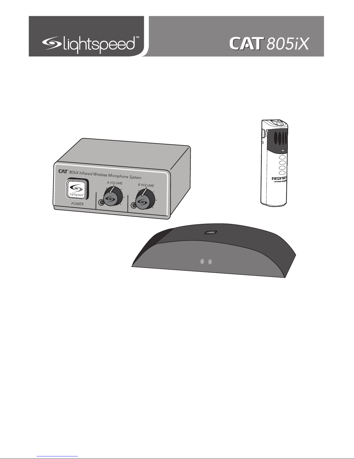
U s e r M a n u a l
Infrared Wireless Microphone System
805iX
Page 2

Page 3

TABLE OF CONTENTS
SECTION 1: 4 System Components and Unpacking
Overview 5 Optional Components
6 Front Panel Controls
7 Rear Panel Controls
8 ISR Connections
9 REDMIKE Controls and Connections
10 Cradle Charger Controls and Connections
SECTION 2: 11 Step 1. Location of the Amplifier
Set-up & Use 12 Step 2. ISR Sensor Installation
15 Step 3A. Connect the power supply
Step 3B. ISR connection
16 Step 3C. Connect CAT 805iX to an amplifier
17 Step 4. Charging the REDMIKE
18 Step 5. Operating the REDMIKE
19 Using REDMIKE to Amplify External Audio
Equipment
SECTION 3: 20 REDMIKE VC
Optional Accessories 20 Controls and Connections
21 Charging
21 Initial Set-Up
22 LT-71
22 Controls and Connections
23 Charging
24 Initial Set-Up
25 REDMIKE Share
25 Controls and Connections
26 Charging
27 Initial Set-Up
28 iR Media Connector
29 Audio Integration
29 Other Optional Accessories
SECTION 4: 30 Troubleshooting Guide
Troubleshooting 31 Tips to Maintain Optimal Audio Performance
SECTION 5: 32 Warranty Statement
Warranty &
Specifications
33 Safety Instructions
34 Safety Warnings and Certifications
35 System Specifications
Page 4
4
1. Overview 2. Setup & Use
3. Optional
Accessories
4. Troubleshooting
5. Warranty, Safety
& Specifications
Preamp Power
Supply
SECTION 1:
OVERVIEW
SYSTEM COMPONENTS AND UNPACKING
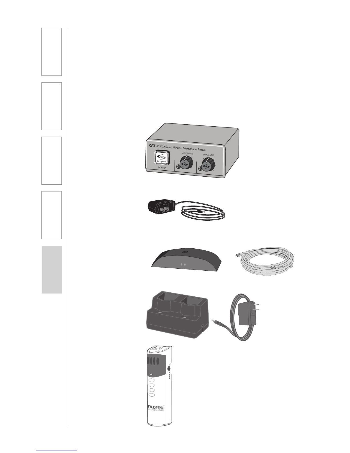
The standard configuration of the CAT 805iX will contain:
ISR Infrared Sensor/
Receiver and Cable
Charging Cradle and
Power Supply
REDMIKE®
Classroom
Microphone
CAT 805iX
Preamp
Page 5

5
1. Overview 2. Setup & Use
3. Optional
Accessories
4. Troubleshooting
5. Warranty, Safety
& Specifications
OPTIONAL COMPONENTS
Optional equipment which may be part of your CAT 805iX system:
REDMIKE® VC
Volume Control
Microphone
LT-71
LT-71 LightMic
and Charger
Cable
Standard Accessories
AC-805 Microphone preamp
PS-24V-250 24V/250mA power supply for CAT 805iX
RX-ISR Infrared sensor/receiver with mounting bracket
CA-P5E50 50’ plenum-rated Cat 5e cable
RMT REDMIKE classroom microphone with battery
BA-NH2A27 AA NiMH rechargeable sensing battery for REDMIKE
AC-RMLC2 REDMIKE lavaliere cord
BC-RMCC REDMIKE cradle charger
PS-5V-1.0 5V/1.0A power supply for cradle charger
Optional Components
RMV REDMIKE VC microphone with battery
RMS REDMIKE Share handheld microphone with battery
pack
LT71 LightMic microphone with batteries
BA-NH2APK NiMH rechargeable battery pack for REDMIKE Share
BA-NH1 AA NiMH rechargeable battery for LT71 (2 per
microphone)
REDMIKE Share
Handheld Microphone
and Charger Cable
Page 6
6
1. Overview 2. Setup & Use
3. Optional
Accessories
4. Troubleshooting
5. Warranty, Safety
& Specifications
805iX Infrared Wireless Microphone System
POWER
A VOLUME B VOLUME
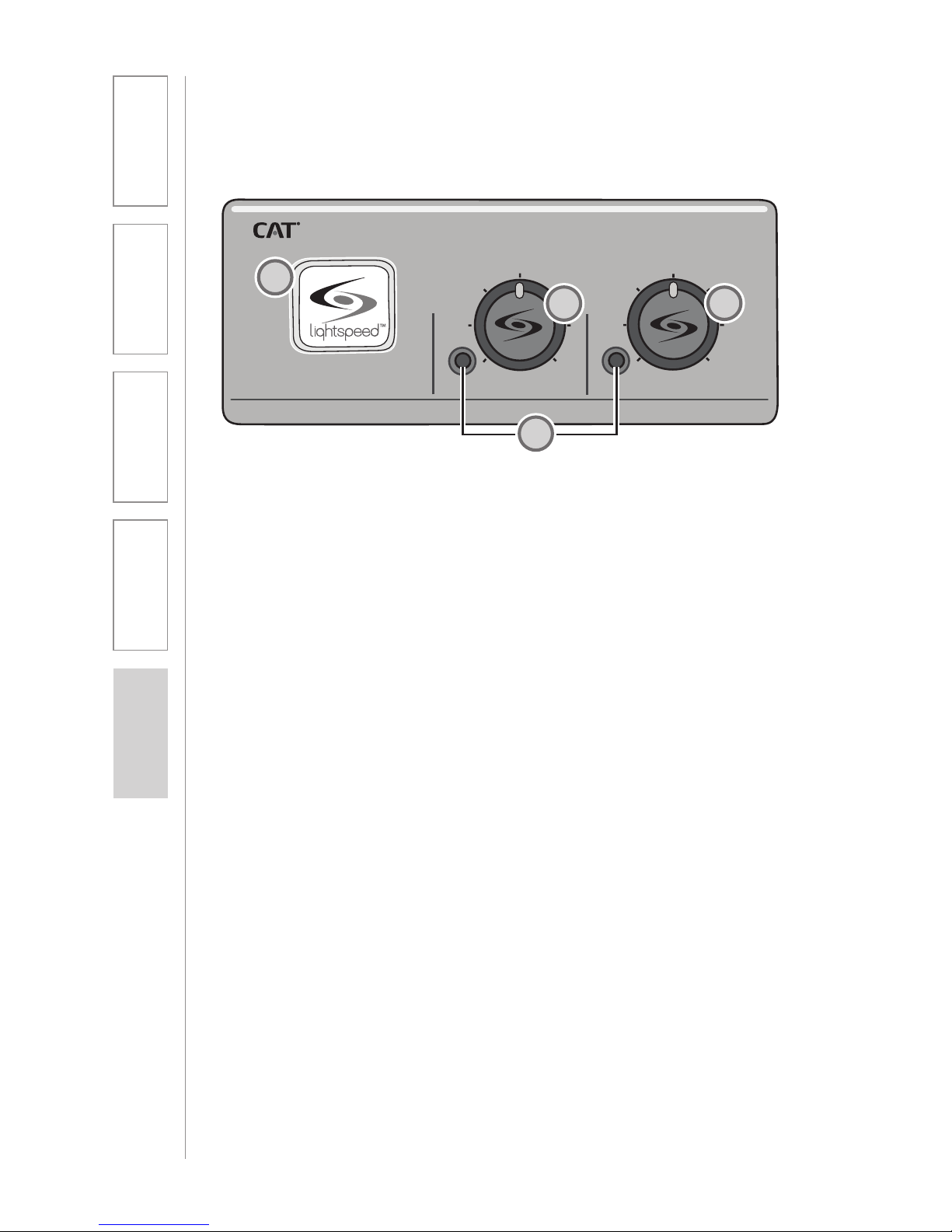
FRONT PANEL CONTROLS
1. POWER SWITCH/INDICATOR:
Press this button to turn the CAT
805iX ON (pushed in) or OFF.
When the POWER is switched on,
the blue LED indicator will light.
2. AUDIO INDICATORS: These
lights flash red when audio (voice)
from the microphone is detected.
3. A VOLUME: Controls the volume
of the teacher microphone (set to
channel A).
4. B VOLUME: Controls the volume
of the student or second teacher
microphone (set to channel B).
2
4
1
3
2
Page 7
7
1. Overview 2. Setup & Use
3. Optional
Accessories
4. Troubleshooting
5. Warranty, Safety
& Specifications
SENSOR
INPUT
SENSOR
SHORT
CH A
CH B
MIXED
24VDC/250mA
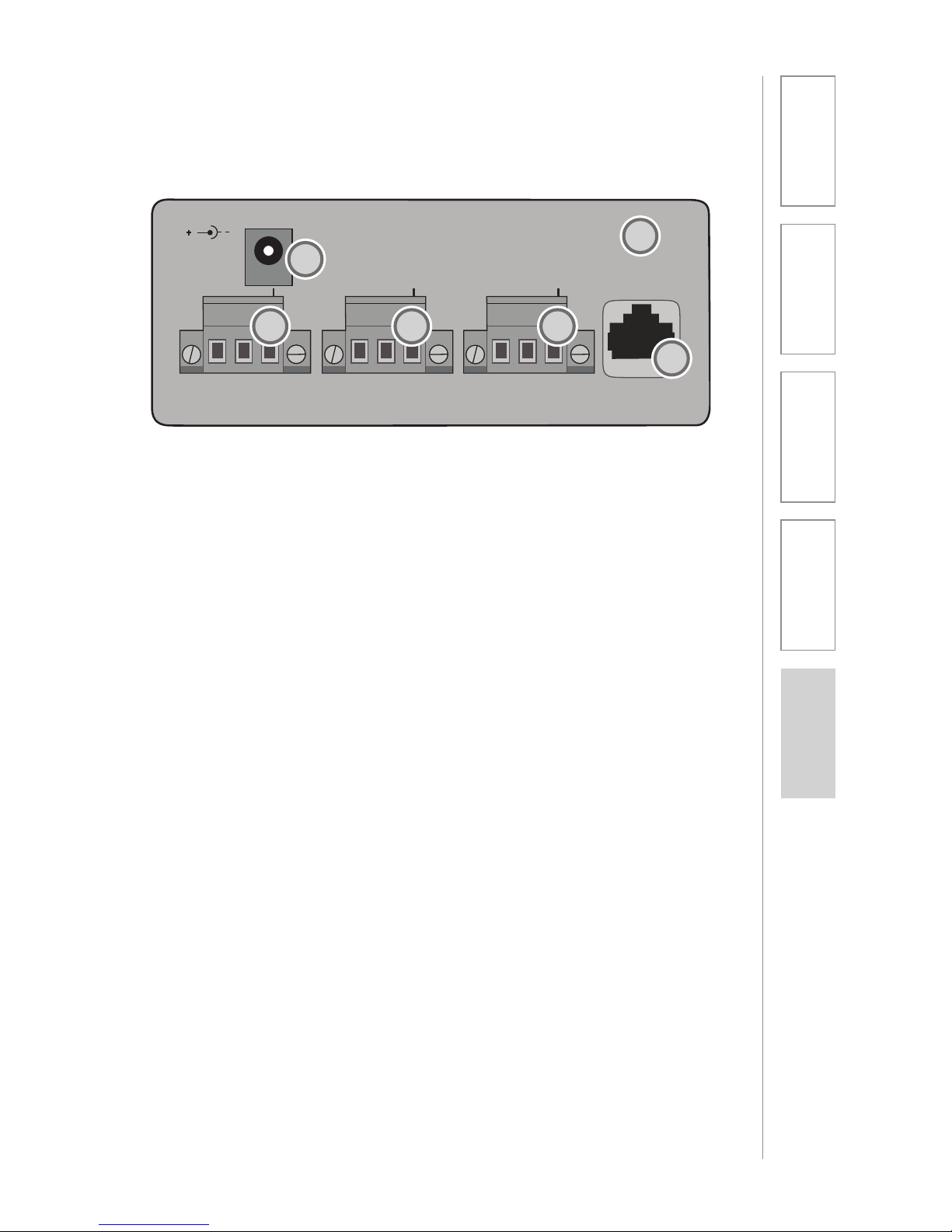
REAR PANEL CONTROLS
1. DC POWER: Plug the power
supply (24V/250mA) into this jack.
2. MIXED OUTPUT: This balanced
output sends the audio from both
microphones (CH. A and CH. B) to
an input on an amplifier.
3. CH B OUTPUT: This balanced
output sends the audio from only
the microphone set to CH. B to an
input on an amplifier.
4. CH A OUTPUT: This balanced
output sends the audio from only
the microphone set to CH. A to an
input on an amplifier.
5. SENSOR INPUT: The infrared
microphone audio from the ISR is
connected to this input via Cat 5
cable.
6. SENSOR SHORT: This LED glows
red when there is a short in the
ISR or cable. The system will not
operate, but is protected from
damage when the LED is lighted.
1
2 3 4
5
6
Page 8
8
1. Overview 2. Setup & Use
3. Optional
Accessories
4. Troubleshooting
5. Warranty, Safety
& Specifications
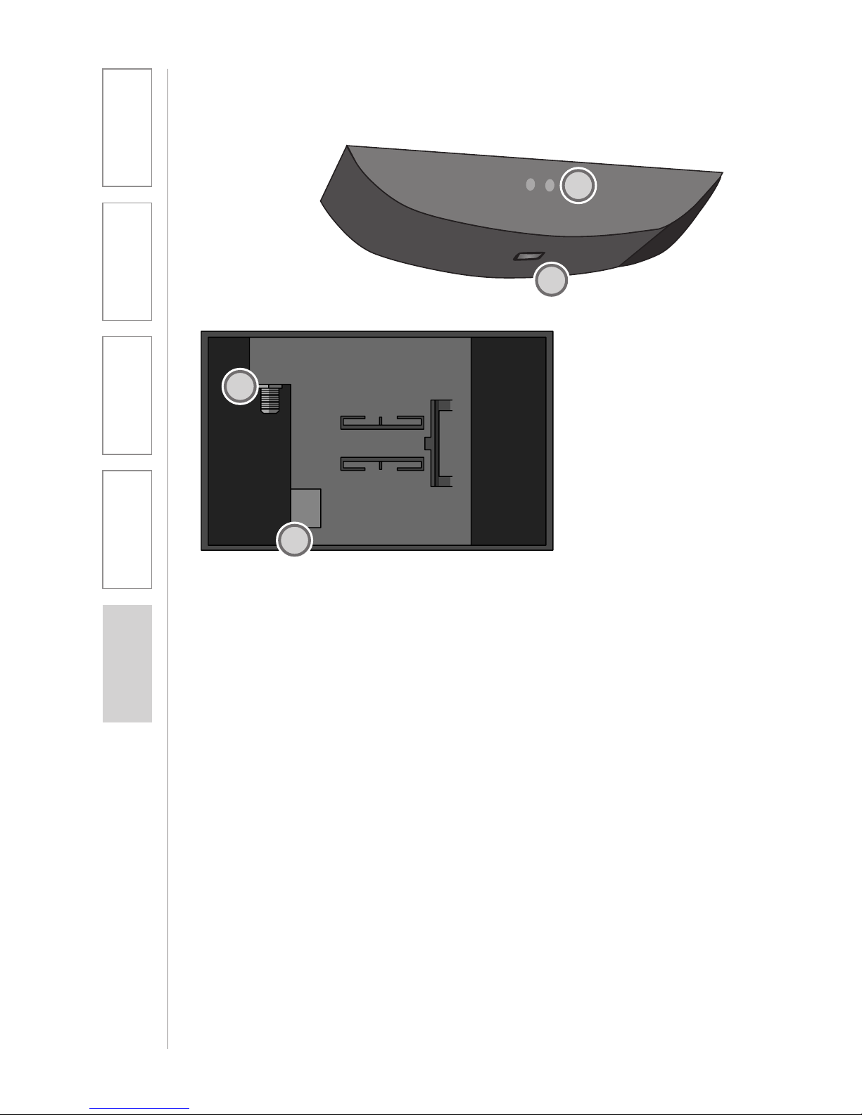
INFRARED SENSOR/RECEIVER (ISR)
CONNECTIONS
1. POWER INDICATOR: This light
will glow blue when the ISR is
receiving power from the CAT
805iX.
2. A/B IR INDICATORS: These lights
glow when the corresponding
microphone (set to channel A or
B) is turned on and transmitting.
A steady light indicates a strong
signal.
3. SENSOR OUT: Connect the Cat 5
sensor cable to this connection to
send audio from the microphones
to the CAT 805iX preamp.
4. IR EXPANSION: Connect up to
three passive IR sensors (IR-SR70F)
to this connection for larger
classrooms. For more than one
additional sensor a 3-way coax
splitter is required (HS3).
1
2
3
4
Page 9

9
1. Overview 2. Setup & Use
3. Optional
Accessories
4. Troubleshooting
5. Warranty, Safety
& Specifications
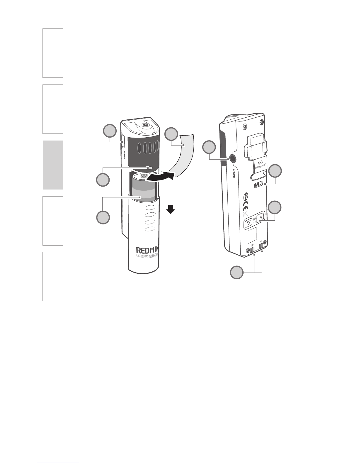
1. POWER BUTTON: Press this
button to turn the REDMIKE ON,
press again to turn it OFF (mute).
2. POWER/LOW BATTERY
INDICATOR: A BLUE light
indicates the REDMIKE is on and
fully charged. A RED light indicates
a charge is needed.
3. BATTERY COMPARTMENT: To
access the battery compartment,
slide the door downward. The
battery should only be replaced
by a Lightspeed AA rechargeable
sensing battery (part # BANH2A27).
4. YELLOW PROTECTIVE TAB:
Slide the battery compartment
door open to remove this
disposable protective tab before
use. NOTE: do not attempt to
remove the tab without first
opening the compartment door, as
it may tear, leaving fragments.
5. AUDIO/MICROPHONE INPUT:
Use this input to plug in a laptop,
MP3 player or other audio
source to wirelessly transmit
audio to be played through the
system. Alternatively, an external
microphone can be connected.
6. CHANNEL SELECT SWITCH
(CH A/B): This switch allows
for selection between Channel
A or B. If you are using a single
microphone, we recommend using
Channel A.
7. CHARGER CONTACTS (+ -):
These contacts interface with the
charging tabs in the BC-RMCC
cradle charger for daily charging.
Simply place the REDMIKE in the
charger.
REDMIKE CONTROLS AND CONNECTIONS
1
2
3
5
6
7
S
l
i
d
e
b
a
t
t
e
r
y
d
o
o
r
o
p
e
n
R
e
m
o
v
e
t
a
b
b
e
f
o
r
e
u
s
e
4
Page 10
10
1. Overview 2. Setup & Use
3. Optional
Accessories
4. Troubleshooting
5. Warranty, Safety
& Specifications
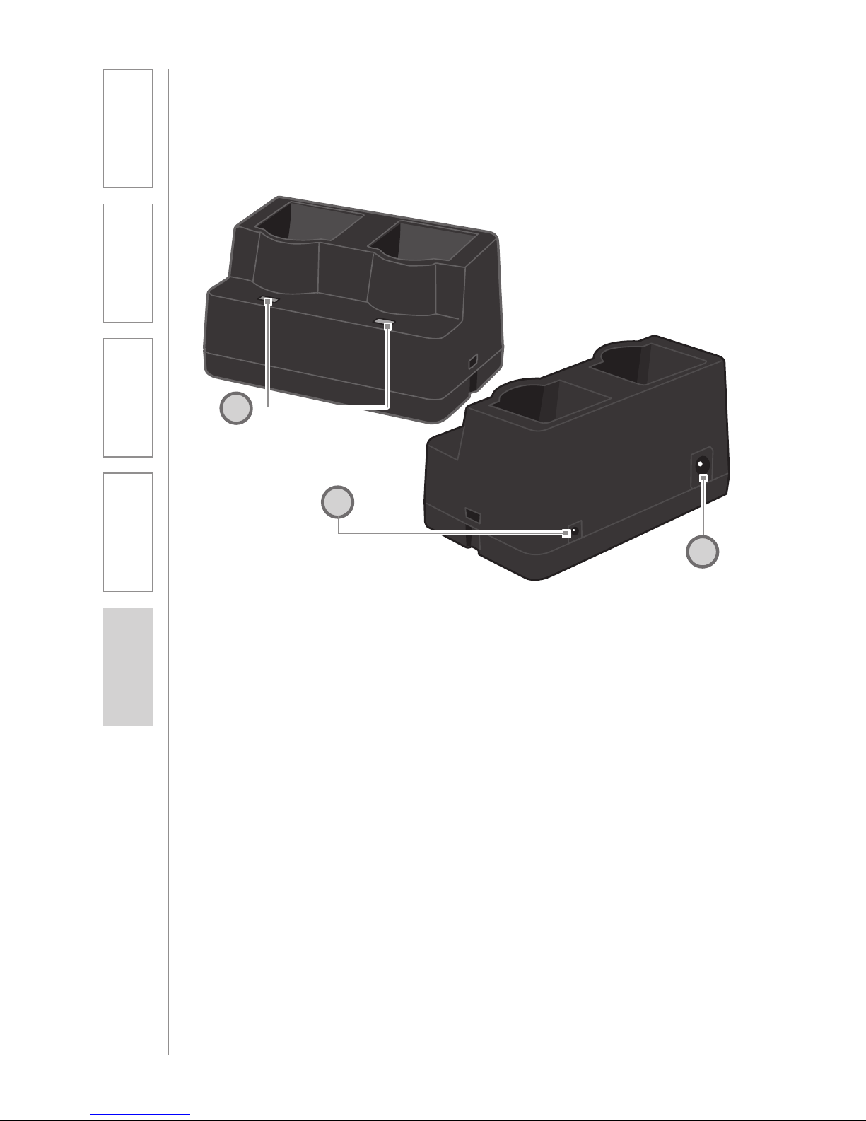
1. CHARGE INDICATORS: The light
glows RED while the REDMIKE is
charging. When fully charged, the
light will glow GREEN. A blinking
RED light indicates that no battery
is sensed, (REDMIKE Yellow
Protective Tab may not have been
completely removed—see page
5, item 4.) A blinking Green LED
means a non- Lightspeed battery
has been installed (possibly an
alkaline battery).
2. DC POWER PORT: Connect the
DC power cord here.
3. OPTIONAL CHARGING PORT:
Plug the charging cord for the
optional LT-71 or the REDMIKE
Share microphones here.
CRADLE CHARGER CONTROLS AND
CONNECTIONS
1
2
3
Page 11
11
1. Overview 2. Setup & Use
3. Optional
Accessories
4. Troubleshooting
5. Warranty, Safety
& Specifications
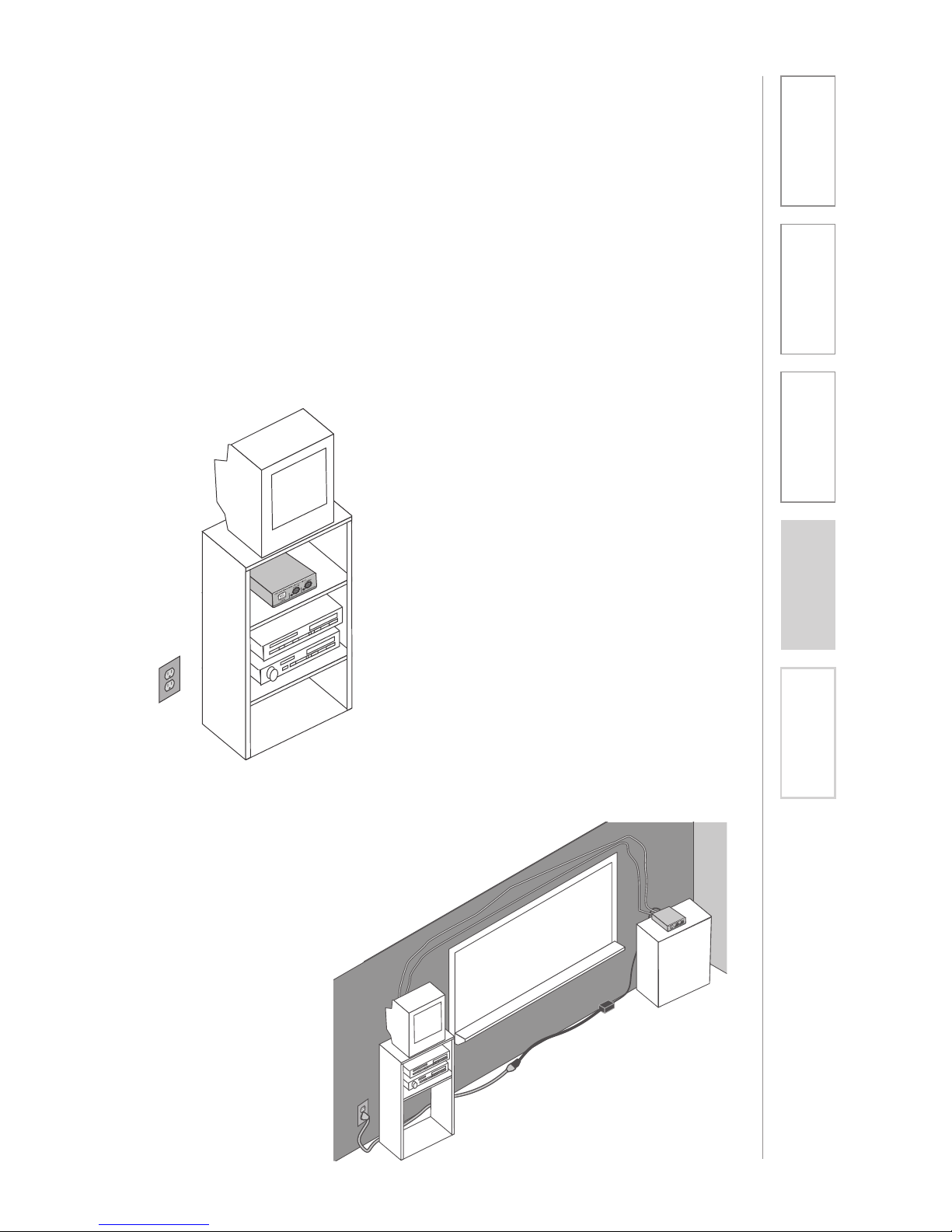
First, find a suitable location to set-up the CAT 805iX preamp. It is best to put the
preamp in a stable location near the amplifier to be used.
Media Cabinet Set-up
SECTION 2:
SET-UP & USE
1. LOCATION OF THE RECEIVER
Avoid Separated Set-ups
Ideally the preamp should be located
very near the amplifier being used.
Avoid long distances when possible
to minimize wire runs and installation
hassle.
Page 12
12
1. Overview 2. Setup & Use
3. Optional
Accessories
4. Troubleshooting
5. Warranty, Safety
& Specifications
2. ISR SENSOR INSTALLATION
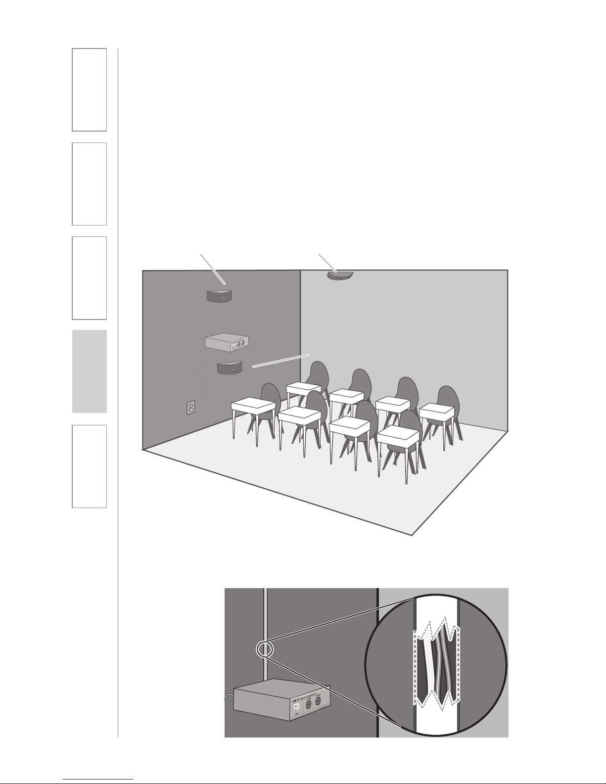
Next, find a suitable location for the ISR. Poor location will cause substandard
performance of the CAT 805iX IR Wireless Microphone System. The ISR should
be as high as possible in the room – the ceiling is the best location, centered
along the longest wall in the room. When possible, use a conduit to protect the
wires (not included). Poor choices for placement are corners, on walls at heights
lower than 7 feet (2 meters), or in places where the line of sight from the ISR to
the receiver is or could be obstructed.
Good placement
Conduit is Recommended
Best placement
Avoid!
Page 13
13
1. Overview 2. Setup & Use
3. Optional
Accessories
4. Troubleshooting
5. Warranty, Safety
& Specifications
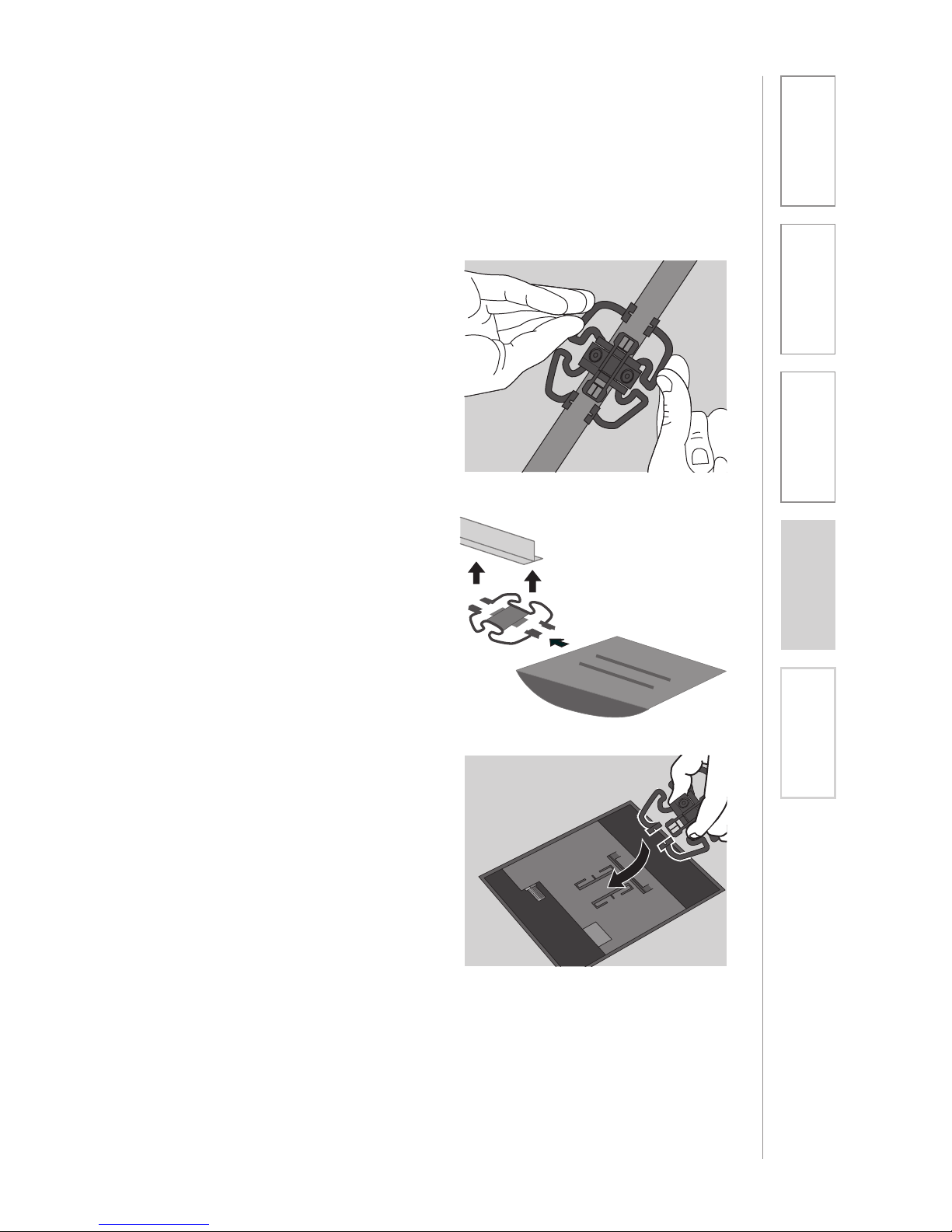
Once you find a suitable location for the ISR, follow these instructions to mount
it. There are different instructions for mounting depending on if the ISR will be
mounted to a suspended ceiling grid or secured to a wall / solid vertical surface.
2. ISR SENSOR INSTALLATION CONT’D
1. Attach the bracket to the ceiling
tile grid (t-bar).
a. Slide the tabs onto the outsides
of the t-bar, starting with one
corner.
b. Attach the second tab around
the other side of the t-bar.
c. Repeat with the other side of
the bracket so it is connected at
all four points.
2. Slide the ISR onto the bracket until
it “clicks” into place.
a. Guide the mounting rails onto
the bracket, oriented as
pictured.
b. Once secure, the ISR locks into
place.
c. To remove the ISR, press the
release bar down and slide the
ISR off the bracket. (We need to
label the “release bar” on the
ISR Image that shows “clip
guide”)
3. Uncoil the Cat 5 sensor cable.
Connect one end of the cable to
the ISR. Secure wire overhead and
route it back to the system.
4. Connect the other end of the Cat
5 sensor cable into the SENSOR
INPUT jack on the CAT 805iX
preamp.
Suspended Ceiling Mount
clip connects to t-bar on ceiling
Page 14
14
1. Overview 2. Setup & Use
3. Optional
Accessories
4. Troubleshooting
5. Warranty, Safety
& Specifications
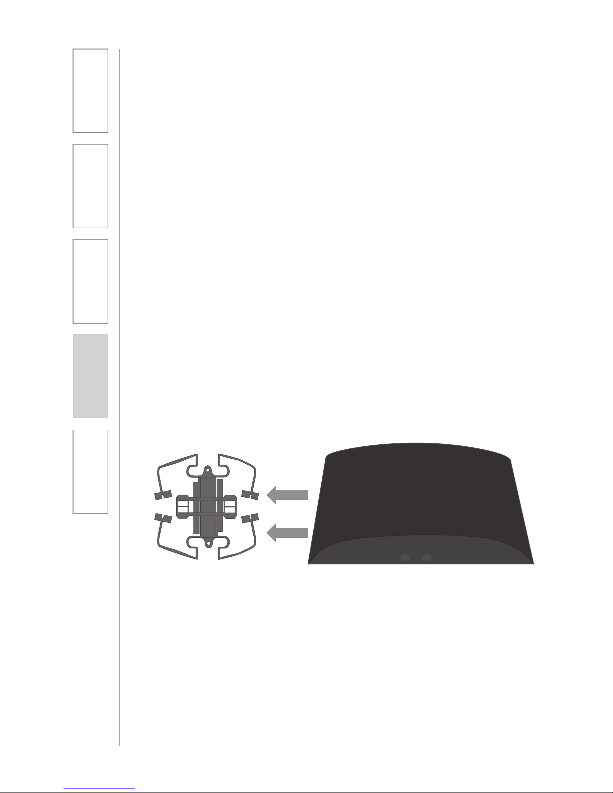
1. Screw the bracket to a place
high on the wall or in the middle
of the solid ceiling. Mount the
bracket horizontally as shown
below.
2. Uncoil the Cat 5 sensor cable.
Connect one end of the cable to
the ISR. Route the wire back to
the CAT 805iX preamp, securing
it along with way using surface
raceway where possible.
3. Slide the ISR onto the bracket
until it “clicks” into place.
a. Guide the mounting rails onto
the bracket, oriented as
pictured.
2. IR SENSOR/RECEIVER (ISR) INSTALLATION
CONT’D
Wall/Solid Ceiling Mount
b. Once secure, the ISR locks
into place.
c. To remove the ISR, slide a ruler
or screwdriver behind the ISR to
press the release bar down and
slide the ISR off the bracket
4. Connect the other end of the Cat 5
sensor cable into the SENSOR INPUT
jack on the CAT 805iX preamp.
Page 15
15
1. Overview 2. Setup & Use
3. Optional
Accessories
4. Troubleshooting
5. Warranty, Safety
& Specifications
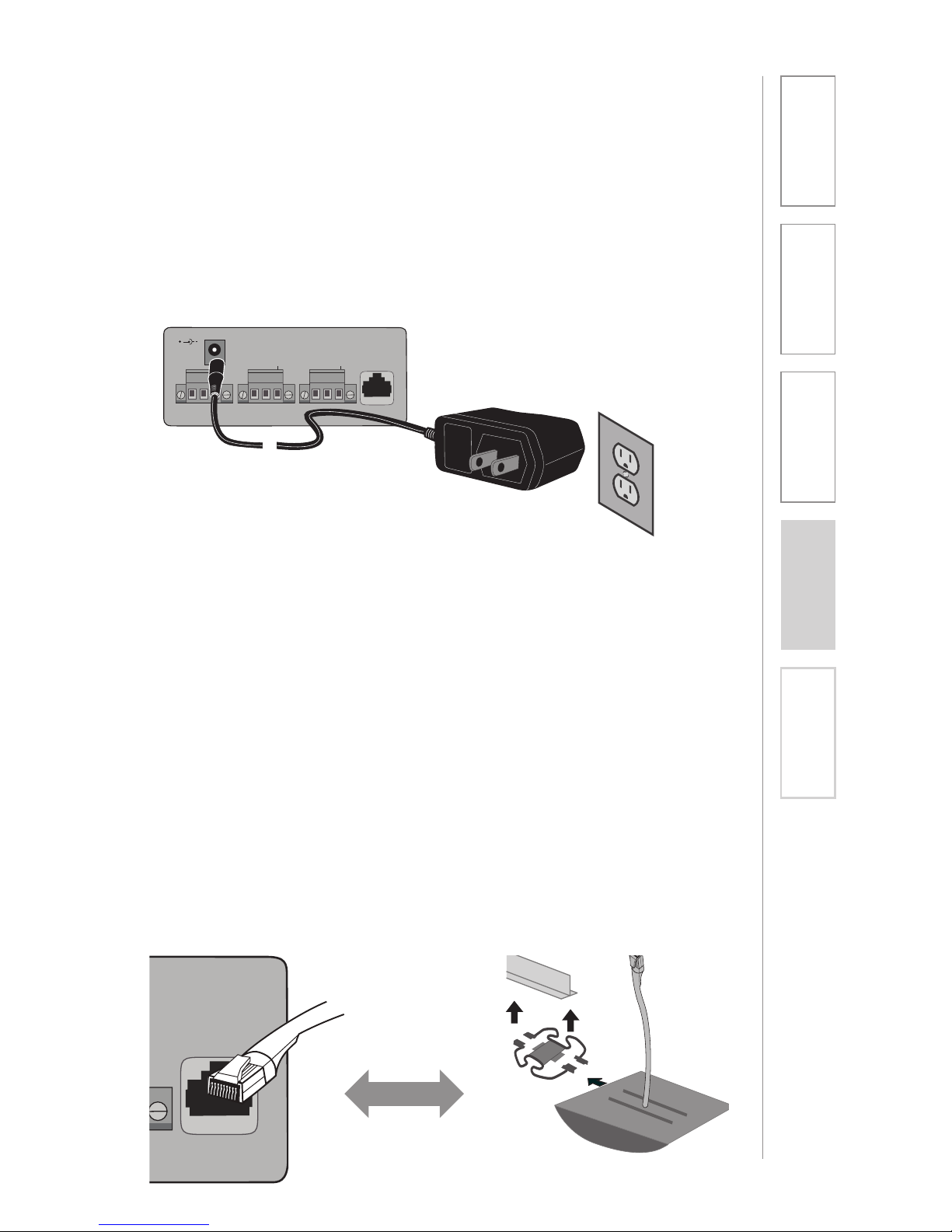
3A. CONNECT THE POWER SUPPLY
3B. ISR CONNECTION
1. Ensure the power button is
depressed in the OFF position
2. Connect the DC end of the power
supply to the 24VDC input
3. Connect the AC adapter end of the
supply into a wall outlet.
1. Ensure the power is still switched
OFF.
2. Check the connection from the
ISR to the CAT 805iX. Ensure the
sensor cable is securely attached
to the SENSOR INPUT jack and
locked into place.
CAT 805iX
DC Power Source Cable
SENSOR
INPUT
T
SENSOR
INPUT
SENSOR
SHORT
CH A
CH B
MIXED
24VDC/250mA
ISR Sensor/Receiver CAT 805iX Preamp
Page 16
16
1. Overview 2. Setup & Use
3. Optional
Accessories
4. Troubleshooting
5. Warranty, Safety
& Specifications
SENSOR
INPUT
SENSOR
SHORT
CH A
CH B
MIXED
24VDC/250mA
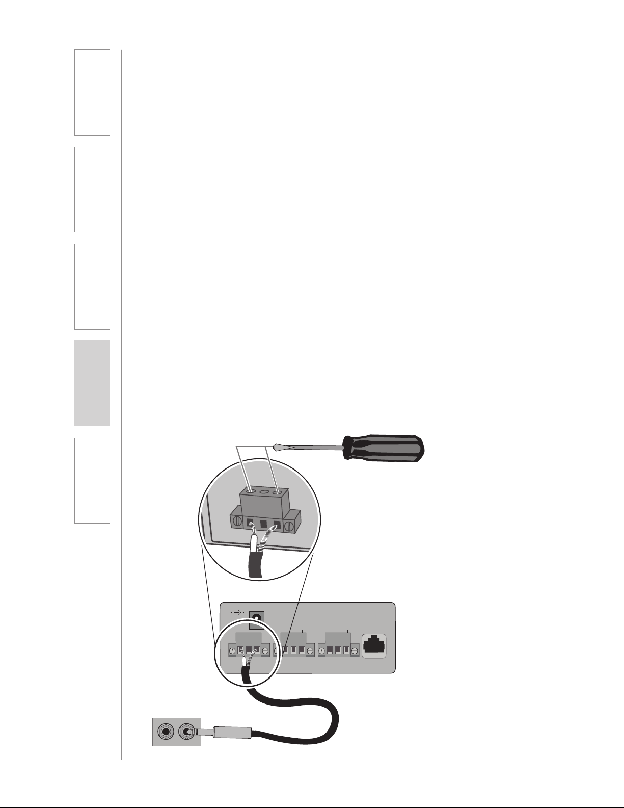
3C. CONNECT CAT 805iX TO AN AMPLIFIER
1. Ensure the power is turned OFF
and the microphone volume
controls are turned all the way
down.
2. Determine whether you wish to
connect to the mixed output or
the individual microphone outputs
(CH. A / CH. B):
a. MIXED OUTPUT
(Recommended for most
applications): connect to this
output if you wish to connect
the mixed signal of micro phone A and microphone B
into a single input on the
amplifier.
b. CH. A/CH. B OUTPUTS:
connect to these outputs if
you wish to use the amplifier to
control each microphone
channel individually.
3. Insert the stripped wires into the
marked openings on the euroblock connector:
a. Unbalanced cable connection
(included cable): connect
the signal wire to the positive
connection (+) and the shield to
the ground.
b. Balanced cable connection
(not included): this connector is
recommended for long cable
runs of 12 feet or more.
Connect the positive and
negative signal wires to the
marked terminals, and the
shield to the ground terminal.
4. Secure the inserted wires by
tightening the retaining screws.
5. Insert the ¼” connector (or other
appropriate connector type) into
an input on the existing amplifier.
SENSOR
INPUT
SENSOR
SHORT
CH A
CH B
MIXED
24VDC/250mA
Page 17
17
1. Overview 2. Setup & Use
3. Optional
Accessories
4. Troubleshooting
5. Warranty, Safety
& Specifications
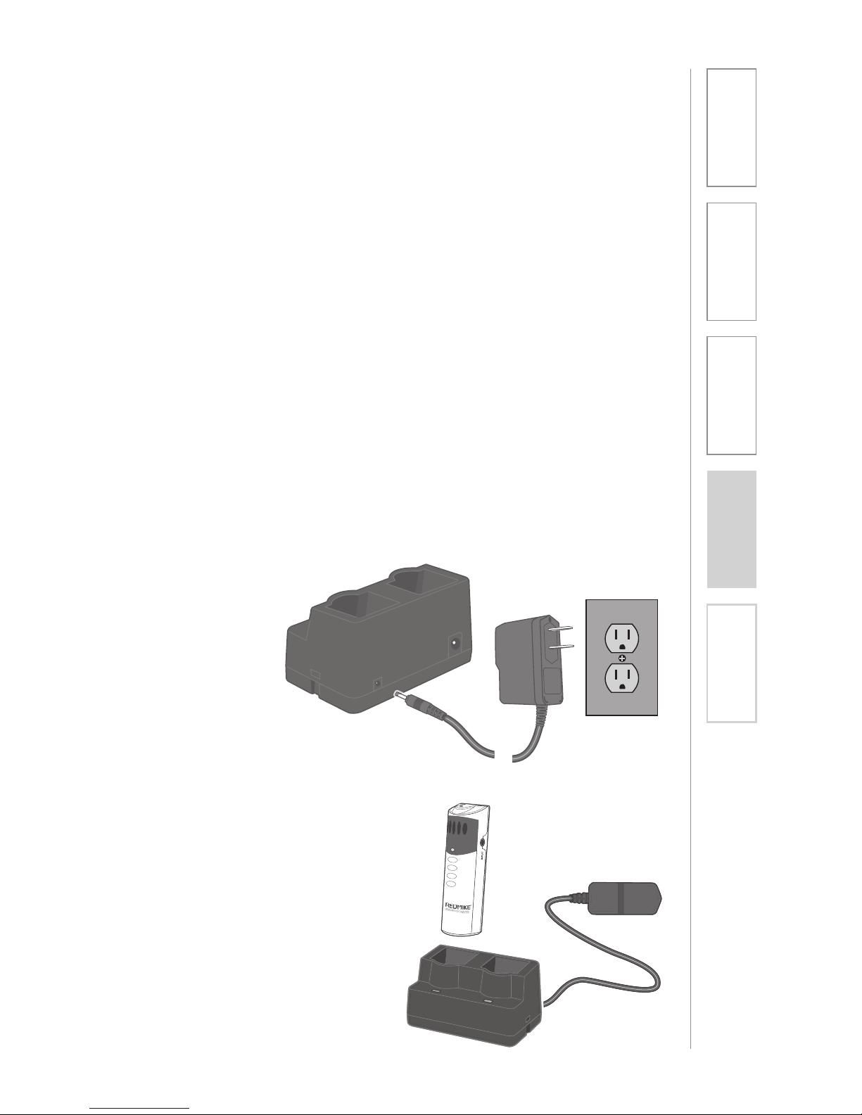
4. CHARGING THE REDMIKE
Before use, the REDMIKE should be charged. It will take 8-9 hours for the
REDMIKE to obtain a full charge. A fully charged REDMIKE will last for over 7
hours of use. If microphones are used daily, they should be kept in the cradle –
microphones can be left in a charging cradle constantly for up to 2 weeks without
causing degradation to battery life.
A red light on the charging cradle indicates the REDMIKE is charging. A green
light indicates that charging is complete and a full charge has been reached. A
blinking light indicates a charging or sensing error. See Troubleshooting section
for more information.
REDMIKE incorporates alkaline protection into the microphone design. Always
use a Lightspeed rechargeable sensing battery. Replacement AA NiMH batteries
may only be purchased through Lightspeed Technologies (part # BA-NH2A27).
Do not attempt to charge alkaline batteries. They can overheat and expand
creating a significant hazard and damaging the microphone (this is not covered
by warranty).
1. Plug power cord into the cradle
charger and then plug the AC end
into an electrical outlet.
2. Ensure that the REDMIKE is turned
OFF.
3. Place the REDMIKE into the
cradle. The LED on the cradle
will glow RED indicating charging
has started. When the REDMIKE
is fully charged the LED on the
cradle charger will change to
GREEN.
Page 18
18
1. Overview 2. Setup & Use
3. Optional
Accessories
4. Troubleshooting
5. Warranty, Safety
& Specifications
5. OPERATING THE REDMIKE
Once the REDMIKE is charged, follow these steps to set it up for use.
1. Turn the CAT 805 power on. The
blue LED will glow.
2. Remove the REDMIKE from the
charging cradle and turn it on.
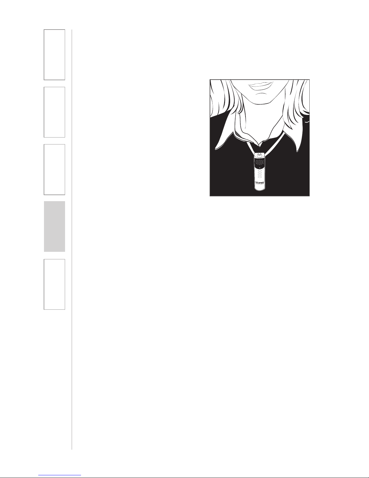
3. Slip the REDMIKE with lanyard
around the neck and position the
top of the microphone just below
the collarbone. NOTE: Positioning
of the REDMIKE is critical for
proper volume adjustment.
4. Set the volume on the existing
amplifier at a normal level (25-30%)
to start with.
5. While speaking in a normal voice
slowly increase the volume of the
corresponding channel on the
CAT 805iX until your voice is barely
audible. Each REDMIKE has its
channel pre-set to either A or B, as
indicated on the back of the Mic.
REMEMBER: This equipment
supplements the user’s voice so they
are able to speak in a conversational
tone. Having the volume set too high
will result in feedback and listener
fatigue.
6. Adjust the corresponding volume
on the amplifier as needed to
achieve an appropriate level
amplified through the speakers.
7. Once initial volume level is set,
walk around the room and listen
for audio dropout and overall
audio quality. Fine-tuning the
audio is accomplished by making
minor adjustments to the volume
levels on the CAT 805iX and/or the
amplifier.
8. If a second REDMIKE was
purchased, repeat steps 2-4.
Page 19
19
1. Overview 2. Setup & Use
3. Optional
Accessories
4. Troubleshooting
5. Warranty, Safety
& Specifications
USING REDMIKE TO AMPLIFY
EXTERNAL AUDIO EQUIPMENT
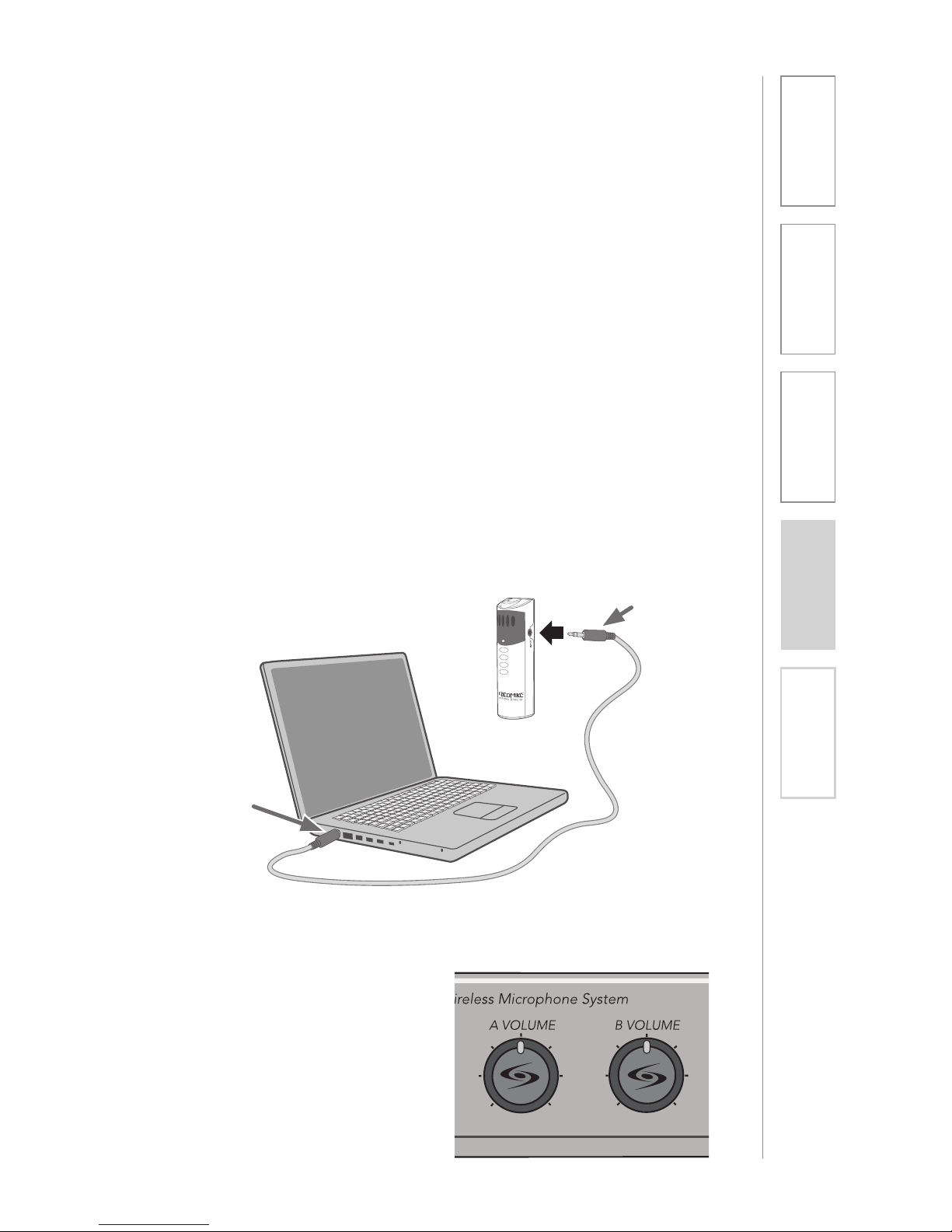
The REDMIKE includes a 3.5mm audio input jack to connect to an audio source
like a laptop or MP3 player. The REDMIKE will transmit the audio signal to be
played through the system.
If your system includes two REDMIKEs, we recommend using Channel B (student
mike) to amplify the external audio equipment so the teacher’s volume on the
Channel A (teacher mike) does not have to be adjusted.
To determine which REDMIKE is set to Channel B, you can look at the switch on
the back of the mike or speak into one of the mics and watch which set of LED’s
glow on the front panel of the CAT 805iX (A Volume or B Volume correspond to
Channels A or B).
1. Plug your external audio
equipment (for example, laptop),
into the input on the REDMIKE
labeled “INPUT” using a 3.5mm
patch cable.
2. Adjust the volume on the CAT
805iX receiver which corresponds
to selected mic channel A or B.
AUDIO
OUTPUT
AUDIO
INPUT
Page 20
20
1. Overview 2. Setup & Use
3. Optional
Accessories
4. Troubleshooting
5. Warranty, Safety
& Specifications
SECTION 3:
OPTIONAL ACCESSORIES
OPTIONAL REDMIKE VC (Volume Control)
Controls and Connections
5
6
7
8
1
2
3
S
l
i
d
e
b
a
t
t
e
r
y
d
o
o
r
o
p
e
n
R
e
m
o
v
e
t
a
b
b
e
f
o
r
e
u
s
e
4
1. POWER /MUTE BUTTON
2. POWER/LOW BATTERY
INDICATOR: A BLUE light
indicates the REDMIKE VC is on
and fully charged. A RED light
indicates a charge is needed.
3. BATTERY COMPARTMENT: To
open, slide the door downward.
The battery should only be
replaced by a Lightspeed AA
rechargeable sensing battery
(part # BA-NH2A27).
4. YELLOW PROTECTIVE TAB:
Slide the battery compartment
door and remove this disposable
protective tab before use.
5. AUDIO/MICROPHONE INPUT:
Use this input to plug in a laptop,
MP3 player or other audio
source to wirelessly transmit
audio to be played through the
system. Alternatively, an external
microphone can be connected.
6. CHANNEL SELECT SWITCH (CH
A/B): Use this to choose Channel
A or B. If you are using a single
microphone, we recommend using
Channel A.
7. VOLUME CONTROLS (UP DOWN)
8. CHARGER CONTACTS (+ -):
These contacts interface with the
charging tabs when the REDMIKE
VC is placed in the BC-RMCC
cradle charger.
Page 21

21
2. Setup & Use
3. Optional
Accessories
1. Overview 4. Troubleshooting
5. Warranty, Safety
& Specifications
REDMIKE VC : Charging
REDMIKE VC : Initial Set-up
Before use, the REDMIKE VC should
be charged. See page 16 and
follow the same instructions for the
REDMIKE.
See page 17 and follow the same
instructions for the REDMIKE to setup
the REDMIKE VC.
NOTE: A nominal volume level must be
set on the CAT 805iX before adjusting
controls on the REDMIKE VC.
The teacher can now use the controls
on the REDMIKE VC to adjust the
volume level from anywhere in the
room. The microphone volume control
has 4 steps up and 4 steps down from
the mid point (9 levels total).
Page 22
22
1. Overview 2. Setup & Use
3. Optional
Accessories
4. Troubleshooting
5. Warranty, Safety
& Specifications
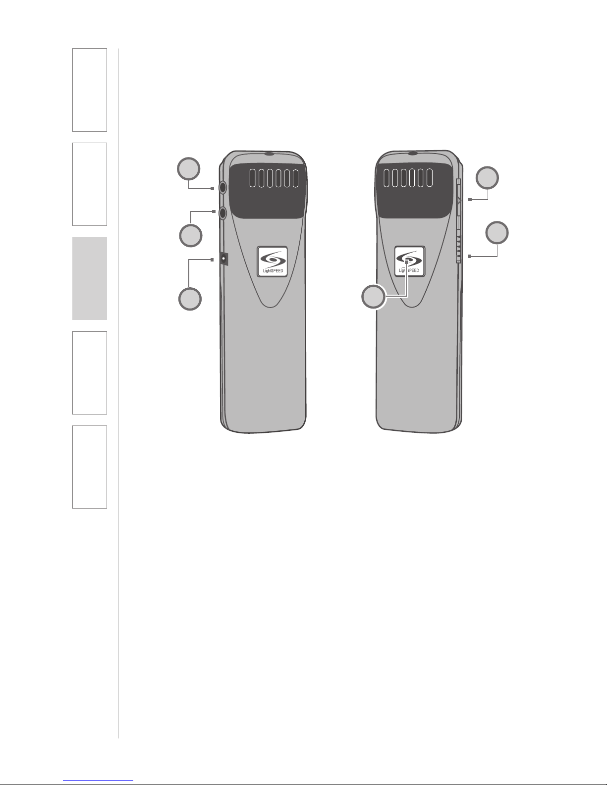
1. ON/OFF/MUTE Switch
2. CHANNEL SELECT SWITCH (CH
A/B): Use this to choose Channel
A or B. If you are using a single
microphone, we recommend using
Channel A.
3. POWER/CHARGE INDICATOR: A
BLUE light indicates the REDMIKE
VC is on and fully charged. A RED
light indicates a charge is needed.
4. EXTERNAL MICROPHONE
INPUT (MIC): Use the 3.5mm
MIC jack for the optional TK-250
headset microphone (part# MCTK250LTM).
5. AUXILIARY (AUX): Plug a laptop,
MP3 player or other audio source
into this jack to wirelessly transmit
the audio signal to be played
through the system.
6. CHARGER INPUT (CHARGER):
Plug the charging cable from the
charger into this jack for daily
charging. The LED on the front will
glow RED to indicate charging.
OPTIONAL LT-71: Controls and Connections
LT- 71
LT- 71
1
2
4
5
6
3
Page 23
23
2. Setup & Use
3. Optional
Accessories
1. Overview 4. Troubleshooting
5. Warranty, Safety
& Specifications
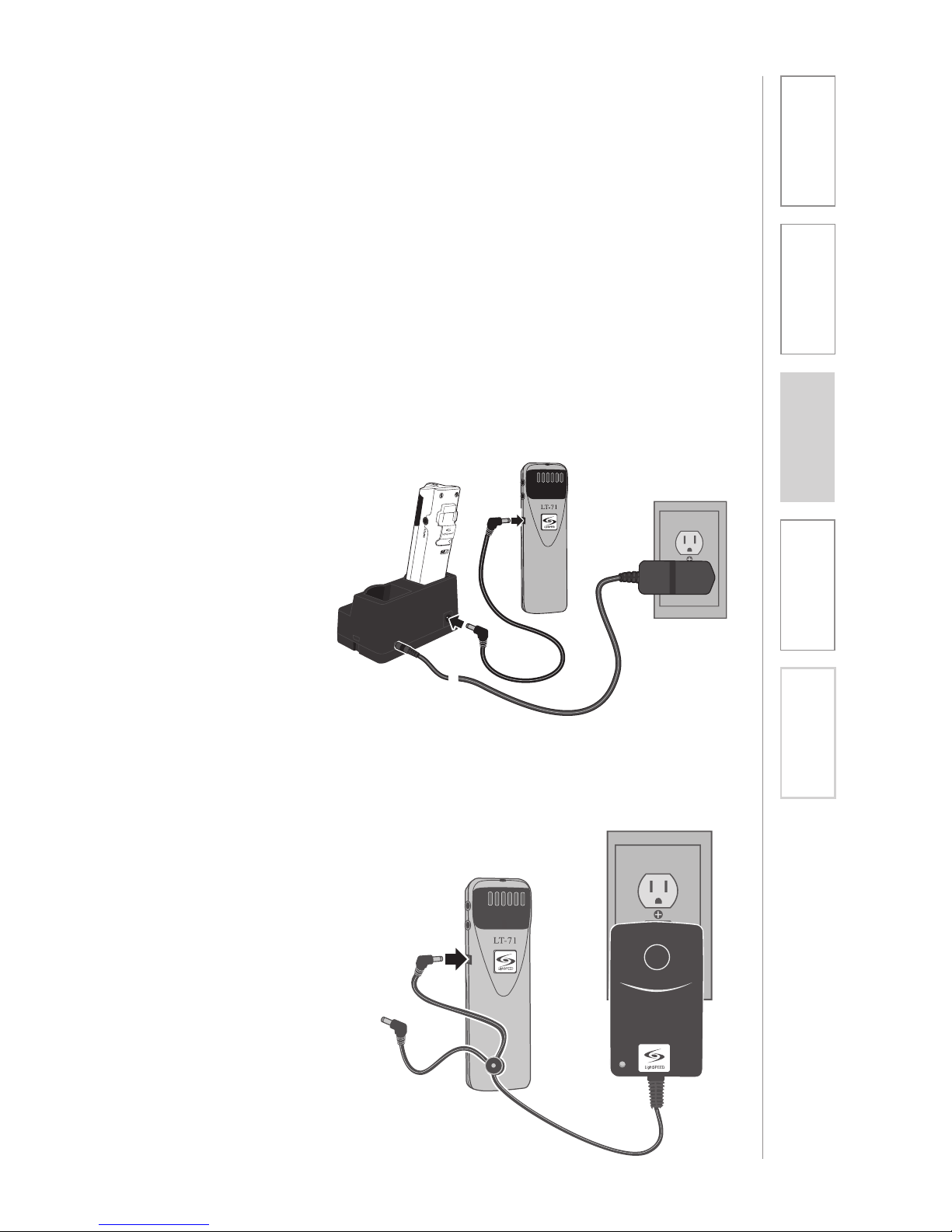
LT-71: Charging
NOTE: If the system was purchased
without a REDMIKE or REDMIKE VC,
the LT-71 will utilize the BC-TXLT wall
charger. Plug the wall charger into an
AC outlet and plug the other end(s)
into the CHARGER jack on the LT-71.
1. Ensure that the LT-71 is turned
OFF.
2. Make sure the cradle charger
is plugged into a wall outlet.
Connect one end of the charging
cable into the jack labeled
CHARGER on the side of the
LT-71 and plug the other end into
the charging jack on the rear of
the REDMIKE cradle charger. The
LT-71’s rechargeable batteries are
factory installed. The LED on the
front of the LT-71 will glow RED
when charging.
3. Leave the LT-71 plugged in
overnight (8–10 hrs.) to obtain
a full charge.
Page 24
24
1. Overview 2. Setup & Use
3. Optional
Accessories
4. Troubleshooting
5. Warranty, Safety
& Specifications
LT-71
LT-71: Initial Set-up
Once the LT-71 is charged, follow these steps to set it up for use.
1. Turn the CAT 805iX power switch
to the ON position. The RED LED
on the switch will glow.
2. Turn on the LT-71 and set the
operating channel to “B”.
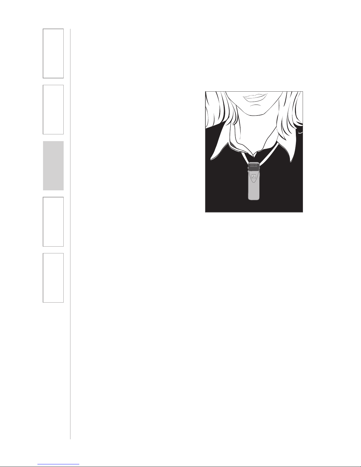
3. Slip the LT-71 with lanyard around
the neck and position the top of
the microphone just below the
collarbone. NOTE: Positioning
of the LT-71 is critical for proper
volume adjustment.
4. While speaking in a normal voice
slowly increase the volume for
Channel B on the CAT 805iX until
your voice is barely audible.
REMEMBER: This equipment
supplements the user’s voice
so they are able to speak in a
conversational tone. Having the
volume set too high will result in
feedback and listener fatigue.
Page 25
25
2. Setup & Use
3. Optional
Accessories
1. Overview 4. Troubleshooting
5. Warranty, Safety
& Specifications
1
2
3
5
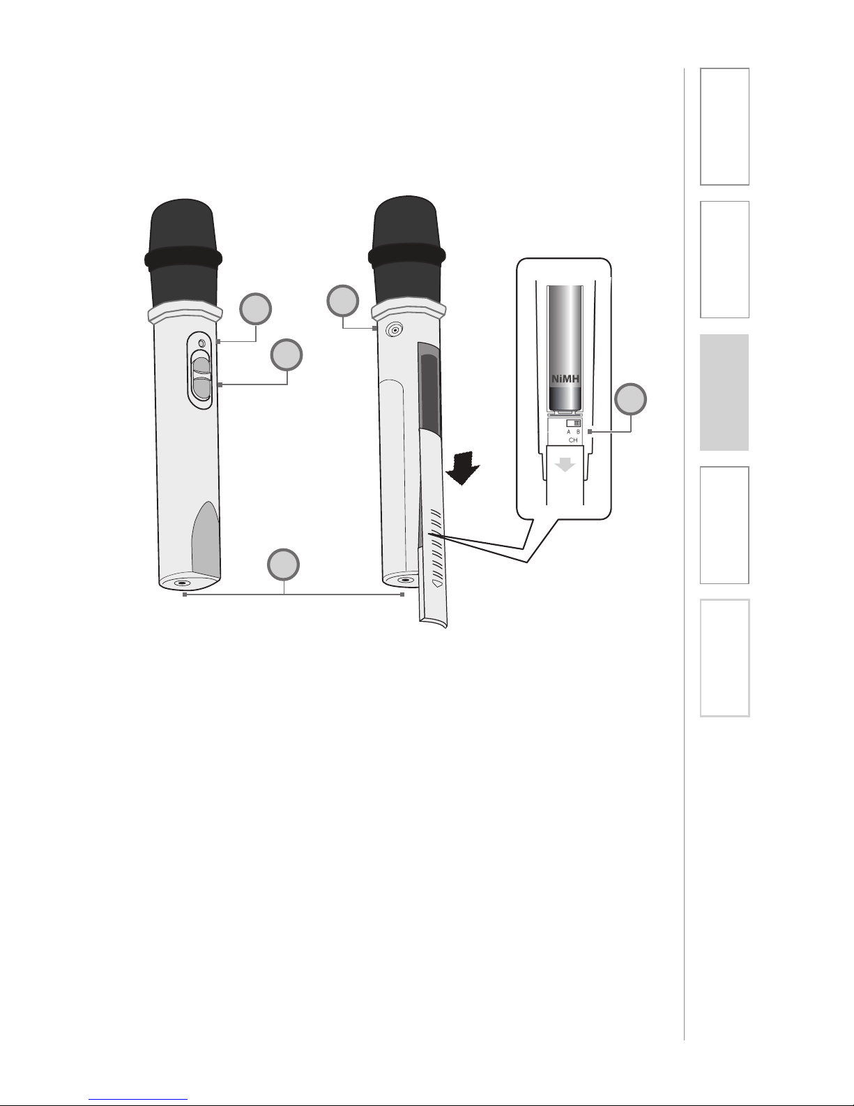
1. POWER SWITCH
2. POWER/CHARGE INDICATOR:
this light glows blue when turned
on and turns off to indicate low
battery level. When charging, the
light glows red.
3. AUDIO INPUT: plug a laptop,
MP3 player or other audio device
into this jack to wirelessly transmit
the audio signal to be played
through the system.
4. CHANNEL SELECT SWITCH
(CH A/B): Located in the battery
compartment, this switch is set to
Channel B at the factory.
5. CHARGER INPUT: Plug the
charging cable from the REDMIKE
cradle charger or into this jack.
REDMIKE Share: Controls and Connections
4
Page 26
26
1. Overview 2. Setup & Use
3. Optional
Accessories
4. Troubleshooting
5. Warranty, Safety
& Specifications
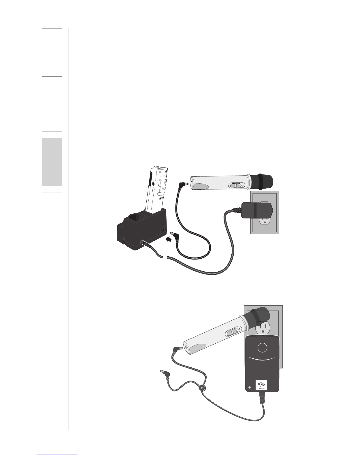
NOTE: If the system was purchased
without a REDMIKE or REDMIKE VC,
the REDMIKE Share will utilize the
BC-TXLT wall charger. Plug the wall
charger into an AC outlet and plug
the other end(s) into the CHARGER
jack on the REDMIKE Share.
1. Ensure that the REDMIKE Share is
turned OFF.
2. Make sure the cradle charger
is plugged into a wall outlet.
Connect one end of the charging
cable into the jack labeled
CHARGER on the bottom of the
REDMIKE Share.
3. Plug the other end into the
charging jack on the rear of the
cradle charger.
4. The LED on the microphone will
glow RED to indicate charging.
5. Leave the REDMIKE Share
plugged in overnight (8-10 hours)
to obtain a full charge.
REDMIKE Share: Charging
Page 27
27
2. Setup & Use
3. Optional
Accessories
1. Overview 4. Troubleshooting
5. Warranty, Safety
& Specifications
REDMIKE Share: Initial Set-up
1. Ensure the CAT 805iX is ON. The blue
LED on the power button will glow.
2. Turn on the REDMIKE Share by sliding
the switch to the top position.
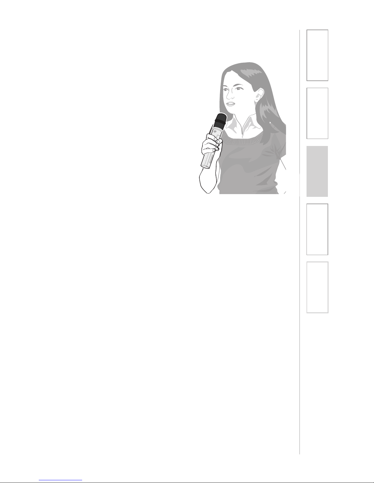
3. Grip the barrel in the center section.
Avoid covering the infrared
emitters just below the microphone
grille. This could interrupt signal
transmission.
4. While speaking in a normal voice,
increase the B VOLUME on the CAT
805iX level until your voice is barely
audible.
REMEMBER: This equipment is designed
to supplement and distribute the user’s
voice so they are able to speak in a
conversational tone. Having the volume
set too high will result in feedback and
listener fatigue.
Page 28
28
1. Overview 2. Setup & Use
3. Optional
Accessories
4. Troubleshooting
5. Warranty, Safety
& Specifications
INITIAL SET-UP:
OPTIONAL IR MEDIA CONNECTOR
1. Turn off the second microphone.
The iR Media Connector uses
the same channel (channel B) as
the optional second microphone
(REDMIKE, LT-71, or REDMIKE
Share). As a result, they cannot be
used simultaneously. If you have
a second microphone, turn it off
before transmitting audio from the
iRMC.
NOTE: If you adjust the CH B
volume on the classroom audio
system, you will also be changing
the volume for your second
microphone. Return the CH B
volume knob to the original
position before turning the second
microphone back on.
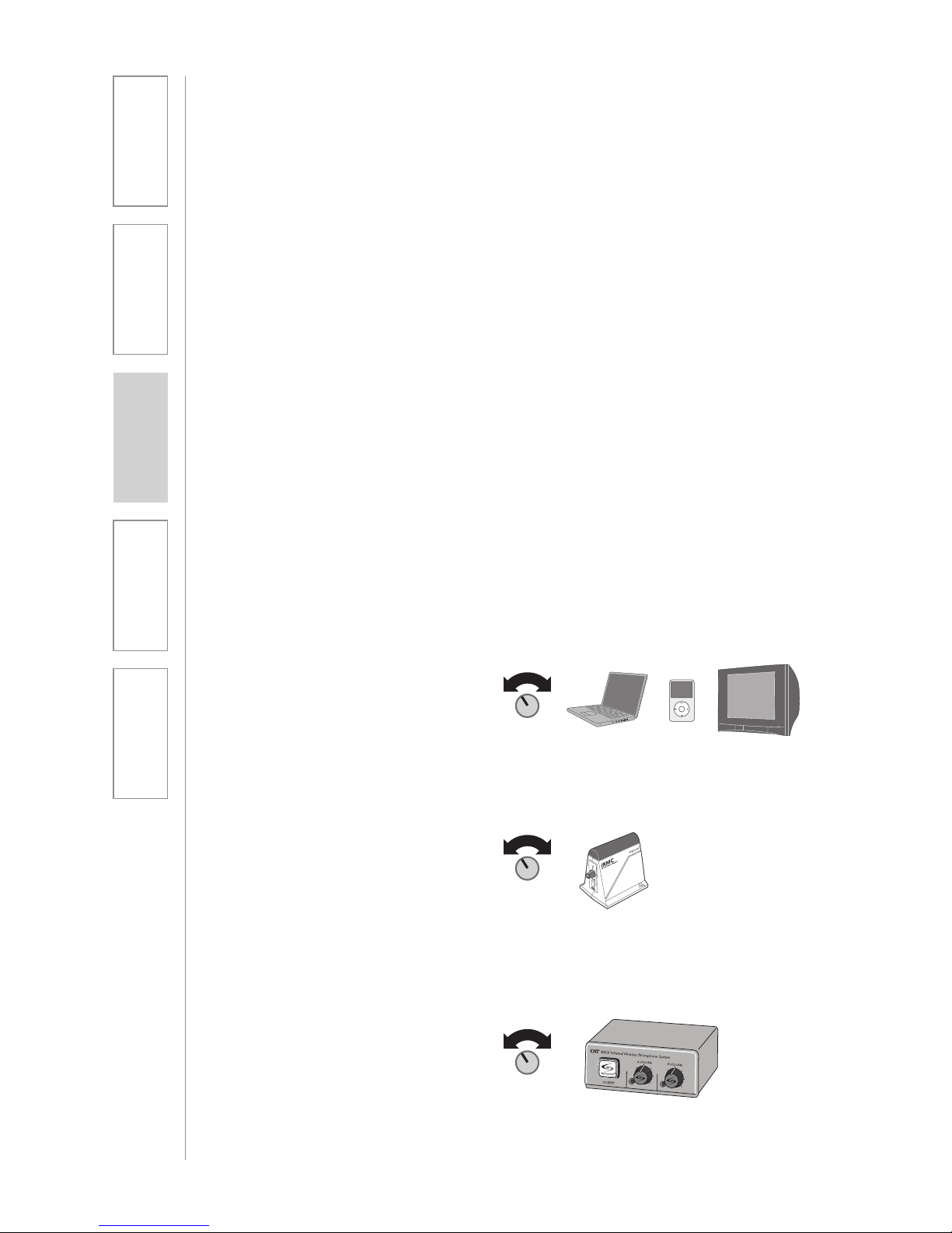
2. The iR Media Connector volume
is preset for most standard audio
signals. If you need to turn the
volume up or down, follow this
procedure:
A. Adjust the volume at the
computer, television, or other
audio source if possible.
B. If the audio source does not
have a volume control (such as
many DVD players) adjust the
volume at the iRMC.
C. If the first two options do not
give optimum volume level, the
last place to adjust the volume
is the CH. B Volume on the CAT
805iX.
Page 29
29
2. Setup & Use
3. Optional
Accessories
1. Overview 4. Troubleshooting
5. Warranty, Safety
& Specifications
OPTIONAL IR MEDIA CONNECTOR AUDIO
INTEGRATION
OTHER OPTIONAL ACCESSORIES
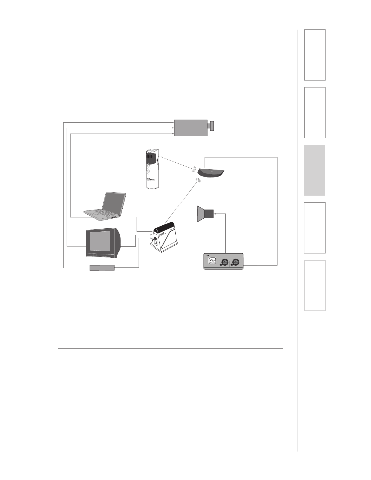
The iRMC is designed to integrate with the CAT 805iX and multiple audio
sources, allowing other instructional technologies to be clearly heard throughout
the classroom.
IRMC Infrared Media Connector
MC-TK250M Noise-canceling headset microphone
AC-TCC7 Charging cable for REDMIKE Share and LT71
Projector
DVD/VCR
Speaker(s)
IR Sensor
iR Media Connector
Projector
Audio In
Audio Out
IR Transmission
Video In
Audio Out
Audio Out
Video Out
Video Out
VGA Out
Teacher’s
Microphone
CAT 805iX
805iX Infrared Wireless Microphone System
POWER
A VOLUME B VOLUME
ISR Sensor
Page 30

30
1. Overview 2. Setup & Use
3. Optional
Accessories
4. Troubleshooting
5. Warranty, Safety
& Specifications
ALL PROBLEMS: Most Problems are
related to low battery power.
SOLUTION: Battery Check
• Confirm batteries are charged
each night.
• Confirm proper batteries are used.
The REDMIKE requires the Lightspeed
BA-NH2A27 rechargeable sensing
battery for proper charging. The
REDMIKE Share uses the BA-NH2APK
rechargeable battery pack. The LT-71
requires two BA-NH1 AA rechargeable
batteries.
• Make sure the microphones are
turned off while charging so a full
charge is attained. Full charge will
last eight hours.
• Inspect the battery contacts. Clean
and adjust if necessary.
PROBLEM: Hearing Static
SOLUTION: Follow these steps to
eliminate static.
• Ensure sensor is in optimum location
(refer to sensor placement in
manual).
A single sensor will cover a 1600 sq.
ft. enclosed classroom.
• Ensure that no other REDMIKE/LT-71/
REDMIKE Share is operating on the
same channel.
• If the optional iR media connection
is in use, set the microphone to
Channel A.
PROBLEM: Low Volume or Feedback
SOLUTION: Follow these steps to
eliminate low volume or feedback.
• Ensure microphone is positioned
appropriately, just below the collar
bone.
• Check volume level on the amplifier.
If the volume is too high, feedback
will occur. Adjust accordingly.
• Adjust the volume level on the back
of the optional REDMIKE VC.
• Turn up the volume on the 805iX if
volume seems too low. If feedback
occurs, try turning down the volume
on the CAT 805iX.
PROBLEM: No Sound From Speaker
SOLUTION: Follow these steps to
produce sound from speakers.
• Turn the CAT 805iX on. Confirm that
the POWER light located on the front
panel switch is on.
• Confirm signal is being received at
the CAT 805iX. The IR signal light will
be RED indicating a signal is being
received.
• Confirm that REDMIKE is turned on.
There will be a BLUE LED on
the microphone to indicate it is
powered on.
• Confirm that the amplifier is turned
on and the volume levels are partially
turned up.
Note: Most problems are directly related to low battery power. Please run
through the “Battery Check” items first. For remaining troubleshooting, use
known good, fully-charged batteries.
If you review these instructions and still have questions, write down the
serial number and model number of your system and call Lightspeed
Technical Services at 800.732.8999, 5 a.m. – 5 p.m., PST.
SECTION 4:
TROUBLESHOOTING
COMMON PROBLEMS AND SOLUTIONS
Page 31

31
1. Overview 2. Setup & Use
3. Optional
Accessories
4. Troubleshooting
5. Warranty, Safety
& Specifications
• Speak in a natural voice. A normal
conversational speech level will
provide an adequate signal.
It is not necessary to increase
the intensity of your voice—the
audio system provides adequate
amplification (approximately 5 – 10
dB) above ambient room noises.
• Avoid wearing jewelry that may rub
or bump against the microphone.
• Turn the REDMIKE off during
private conversations with a
student, parent, or other classroom
visitor. You can also cover the LED
lens on top of the REDMIKE to
block the signal.
• Recharge batteries each night.
When recharged nightly, operating
time (actual usage) for the
transmitters will last through a
typical school day.
TIPS TO OBTAIN OPTIMUM AUDIO
PERFORMANCE
Page 32

32
1. Overview 2. Setup & Use
3. Optional
Accessories
4. Troubleshooting
5. Warranty, Safety
& Specifications
FIVE-YEAR LIMITED WARRANTY
Our Service Department (800.732.8999, 5 a.m. – 5 p.m., PST) will handle all your
repair/replacement needs.
SECTION 5:
WARRANTY, SAFETY &
SPECIFICATIONS
Lightspeed Classroom Audio Systems are guaranteed against malfunction due to
defects in materials and workmanship for a period of FIVE (5) YEARS, beginning
at the date of the purchase invoice. If such malfunction occurs, the product
will be repaired or replaced (at Lightspeed’s option) without charge during the
warranty period.
Lightspeed’s Warranty Exchange Program applies to all infrared systems within
the five (5) year warranty period. If an infrared product or component has an
issue that requires service, a refurbished replacement will immediately be sent
to the customer to minimize downtime. Customers will receive the exchange
product(s) or component(s) within 2-3 days. A prepaid return label will be
included with exchanged products so original malfunctioned equipment can
be returned to Lightspeed. Any exchanged equipment will remain covered
under the original five (5) year warranty.
1. Warranty on infrared microphones is FIVE (5) YEARS.
2. Warranty on Lightspeed NiMH rechargeable batteries is one (1) year.
3. Prepaid shipping label provided by Lightspeed for warranty repairs within the
U.S. Customers outside the U.S. should refer to the Lightspeed website (www.
lightspeed-tek.com) for warranty repair instructions.
4. Warranty does not extend to finish, appearance items, or malfunctions due
to abuse or operation other than specified conditions, nor does it extend to
incidental or consequential damages. Repair by other than Lightspeed or its
authorized service agencies will void this guarantee. Information on authorized
service agencies is available from Lightspeed Technologies, Inc.
Page 33

33
1. Overview 2. Setup & Use
3. Optional
Accessories
4. Troubleshooting
5. Warranty, Safety
& Specifications
IMPORTANT SAFETY INSTRUCTIONS
1. Read these instructions.
2. Keep these instructions.
3. Heed all warnings.
4. Follow all instructions.
5. Do not use the apparatus
near water.
6. Clean only with dry cloth.
7. Do not block any ventilation
openings. Install in
accordance with the
manufacturer’s instructions.
8. Do not install near any heat
sources such as radiators,
heat registers, stoves, or
other apparatus (including
amplifiers) that produce
heat.
9. Do not defeat the safety
purpose of the polarized
or grounding-type plug.
A polarized plug has two
blades with one wider than
the other. A groundingtype plug has two blades
and a third grounding
prong. The wide blade or
the third prong is provided
for your safety. If the
provided plug does not fit
into your outlet, consult an
electrician for replacement
of the obsolete outlet.
10. Protect the power cord
from being walked on
or pinched particularly
at plugs, convenience
receptacles, and the point
where they exit from the
apparatus.
11. Only use attachments/
accessories specified by the
manufacturer.
12. Use only with a cart,
stand, tripod, bracket or
table specified by the
manufacturer, or sold with
the apparatus. When a cart
is used, use caution when
moving the cart/apparatus
combination to avoid injury
from tip-over.
13. Unplug this apparatus
during lighting storms
or when unused for long
periods of time.
14. Refer all servicing to
qualified service personnel.
Servicing is required when
the apparatus has been
damaged in any way, such
as power-supply cord or
plug is damaged, liquid has
been spilled or objects have
fallen into the apparatus,
the apparatus has been
exposed to rain or moisture,
does not operate normally,
or has been dropped.
15. When the mains plug or
appliance coupler used
as the disconnect device,
it shall remain readily
operable.
16. Please keep the unit
in a good ventilation
environment.
Page 34
34
1. Overview 2. Setup & Use
3. Optional
Accessories
4. Troubleshooting
5. Warranty, Safety
& Specifications
SAFETY WARNINGS AND CERTIFICATIONS
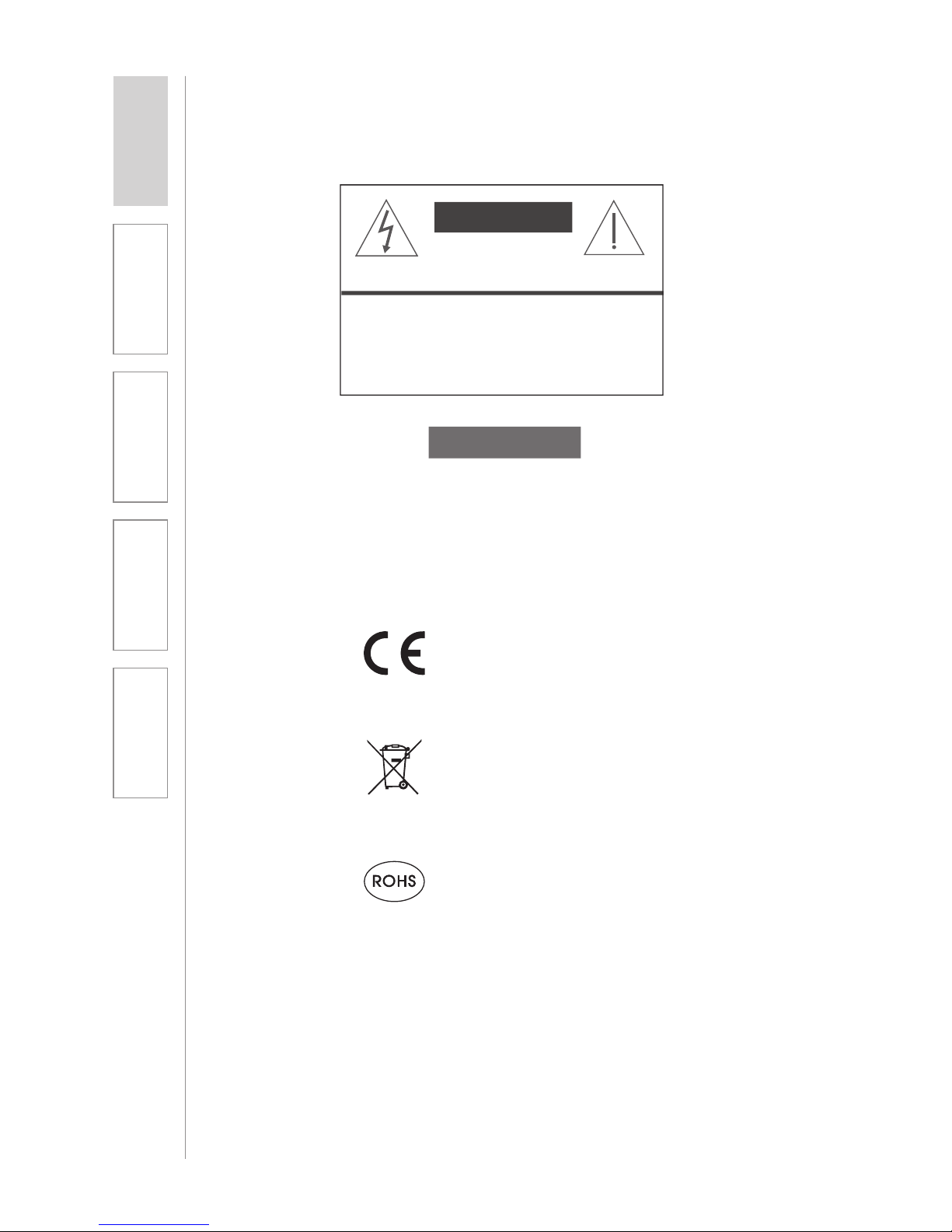
CAUTION: TO REDUCE THE RISK OF ELECTRIC SHOCK
DO NOT REMOVE COVER (OR BACK)
NO USER-SERVICEABLE PARTS INSIDE
REFER SERVICING TO QUALIFIED PERSONNEL
RISK OF ELECTRIC SHOCK DO NOT OPEN
CAUTION
CERTIFICATIONS
This product conforms with the essential
requirements of the following European Union
Directives: 89/336/EEC, 92/31/EEC, 93/68/
EED, and 2004/108/EC Electromagnetic
Compatibility Directives.
Lightspeed Technologies launched a formal
product recycle program in Europe that
complies with the European Union Directive
2002/96/EC on Waste Electrical and Electronic
Equipment (“WEEE Directive”). Please visit our
website at www.Lightspeed-tek.com for more
information.
This product is manufactured using lead-free
processes and is free of other materials
harmful to the environment. It conforms to the
most stringent new European guidelines for
consumer products (RoHS).
Page 35

35
1. Overview 2. Setup & Use
3. Optional
Accessories
4. Troubleshooting
5. Warranty, Safety
& Specifications
OVERALL SPECIFICATIONS
Audio Output Level 500mV
Frequency Response 100 Hz to 10 kHz ±3 dB
Carrier Frequencies (IR) 2.06/2.54; 3.2/3.7 MHz
Signal-to-Noise Ratio > 73 dB
Image and Spurious Rejection > 70 dB
RECEIVER SPECIFICATIONS
Receiver Type Superheterodyne
Receiver Sensitivity 6 µV for 60 dB S/N
Image and Spurious Rejection > 70 dB
Dimensions (W x D x H) 4.2” x 4” x 1.8”
Weight 0.95 lbs.
TRANSMITTER SPECIFICATIONS
REDMIKE and REDMIKE VC
Audio Distortion < 1 %
Built-in Microphone Unidirectional Electret
Battery Power (1-year warranty) 1 AA NiMH Rechargeable
Sensing Battery
Audio Input 3.5 mm
Dimensions (W x D x H) 0.9” x 1.0” x 3.5”
Weight 2.1 oz.
LT-71 LightMic
Audio Distortion < 1 %
Built-in Microphone Unidirectional Electret
Battery Power (1-year warranty) 2 AA NiMH Rechargeable
Audio Inputs Mic Level 3.5 mm, Line Level 3.5 mm
Dimensions (W x D x H) 1.375” x .75” x 4.625”
Weight 3.7 oz.
REDMIKE Share Handheld Microphone
Audio Distortion < 1 %
Built-in Microphone Unidirectional Electret
Battery Power (1-year warranty) 1 AA NiMH Rechargeable
Battery Pack
Audio Input 3.5 mm
Dimensions (W x D x H) 8.25” x 1.3” x 1.3”
Weight 7.9 oz.
ISR SENSOR SPECIFICATIONS
Working Range Up to 1600 square feet per sensor
Cable 50 ft., Plenum-rated Cat 5e
Mounting Ceiling clip/Wall bracket
Dimensions 9.4” x 1.4” x 5.2”
Weight 14.3 oz.
SYSTEM SPECIFICATIONS
Page 36

LIGH T S P EED T E C HNOLO G I E S
1150 9 S W HER M A N ROA D / TUAL ATIN, O R 97062
TOLL F R EE: 8 0 0 .732. 8 9 9 9 / P H O NE: 5 0 3 . 684.5 5 3 8 / FAX: 50 3 . 684.3 1 9 7
LIGH T S P EED-T E K .COM
MN0234US01-2
 Loading...