

Page 1
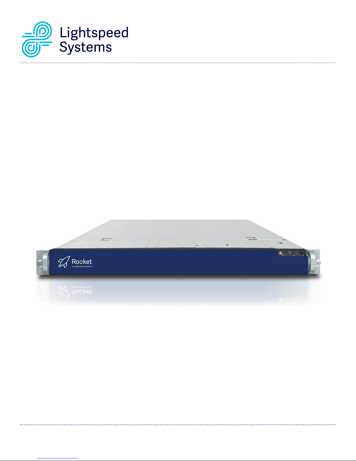
Lightspeed Rocket
Hardware Installation Guide
1800 19th Street / Bakersfield, CA 93301 / Tel: 661.716.7600 / Toll Free: 877.447.6244 / www.lightspeedsystems.com
Page 2

Table of Contents
Section 1 Safety Notice and Warnings . . . . . . . . . . . . . . . . . . . . . . . . . . . . . . . . . . . . . . . . . . . . . . . . . . . . . 3
Section 2 Ratings . . . . . . . . . . . . . . . . . . . . . . . . . . . . . . . . . . . . . . . . . . . . . . . . . . . . . . . . . . . . . . . . . . . . . . 3
Section 3 Electrical and General Safety Guidelines . . . . . . . . . . . . . . . . . . . . . . . . . . . . . . . . . . . . . . . . . . . 4
Section 4 Site Preparation . . . . . . . . . . . . . . . . . . . . . . . . . . . . . . . . . . . . . . . . . . . . . . . . . . . . . . . . . . . . . . . 6
Section 5 Unpacking and Installing the Appliance in the Rack . . . . . . . . . . . . . . . . . . . . . . . . . . . . . . . . . . 6
Section 6A Lightspeed Rocket Email Management - 1Gb Rear Panel Connections . . . . . . . . . . . . . . . . . . . 7
Section 6B Lightspeed Web Filter Policy Parent Rear Panel Connections . . . . . . . . . . . . . . . . . . . . . . . . . . . 8
Section 6C Lightspeed Rocket Web Filter - 1Gb Rear Panel Connections . . . . . . . . . . . . . . . . . . . . . . . . . . 9
Section 6D Lightspeed Rocket Web Filter - 1Gb Fiber Rear Panel Connections . . . . . . . . . . . . . . . . . . . . . . 10
Section 6E Lightspeed Rocket Web Filter and Traffic Bridge - 10Gb Fiber Rear Panel Connections . . . . . . 11
Section 6F Lightspeed Rocket Web Filter - Dual Bridge 1Gb Fiber Rear Panel Connections . . . . . . . . . . . 12
Section 7 Front Panel Operation and End User License Agreement (EULA) . . . . . . . . . . . . . . . . . . . . . . . 13
Section 8 Bezel Installation on the Appliance . . . . . . . . . . . . . . . . . . . . . . . . . . . . . . . . . . . . . . . . . . . . . . .14
Lightspeed Rocket Hardware Installation Guide 2
Page 3
1. Safety Notice and Warnings
FCC Notice
This device complies with part 15 of the FCC Rules. Operation is subject to the following two conditions:
1. This device may not cause harmful interference.
2. This device must accept any interference received, including interference that may cause
undesired operation.
No Telecommunications Network Voltage (TNV)-connected PCBs shall be installed.
CAN ICES-3 (A)/NMB-3(A)
CE Mark Warning
This is a Class A product. In a domestic environment, this product may cause radio interference,
in which case the user may be required to take adequate measures.
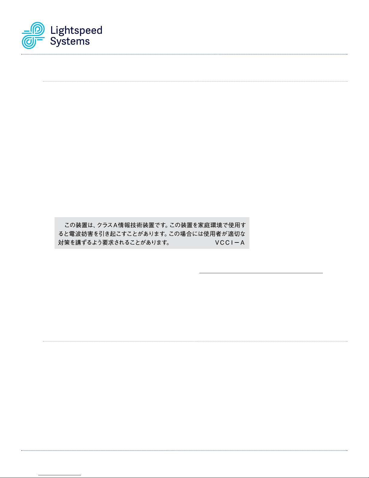
VCCI Warning
This is a product of VCCI Class A Compliance.
Environmental Warning
Perchlorate Material - special handling may apply. See www.dtsc.ca.gov/hazardouswaste/perchlorate.
This notice is required by California Code of Regulations, Title 22, Division 4.5, Chapter 33: Best Management
Practices for Perchlorate Materials. This product/part includes a battery that contains perchlorate material.
2. Ratings
AC input voltage: 100 - 240 VAC (auto-range)
Hz: 50/60
A: 100 - 127V ~/4A Max
200 - 240V ~/2A Max
Lightspeed Rocket Hardware Installation Guide 3
Page 4
3. Electrical and General Safety Guidelines
CAUTION
This appliance is intended for installation in restricted areas only. Initial setup and maintenance should be
performed by qualified personnel.
CAUTION
Power down the appliance following the operating system’s proper power down procedure using the
front panel power button. Unplug the AC power cord(s) before servicing.
CAUTION
To avoid electrical shock, check the power cords as follows:
• This product is to be installed in Restricted Access Location only.
• Use the exact type of power cords required.
• Use power cord(s) that came with safety certifications.
• Power cord(s) must comply with AC voltage requirements in your region.
• The power cord plug cap must have an electrical current rating that is at least 125% of the electrical
current rating of this product.
• The power cord plug cap that plugs into the AC receptacle on the power supply must be an IEC 320,
sheet C13, type female connector.
• Plug the power cord(s) into a socket that is properly grounded before turning on the power.
CAUTION
Required operating conditions for the appliance are:
• Temperature: 10 to 35oC.
• Humidity, non-condensing: 8 to 90%.
CAUTION
CLASS 1 LASER PRODUCT
APPAREIL À LASER DE CLASSE 1.
CAUTION
Risk of explosion if the battery is installed upside down or is replaced by an incorrect type.
Dispose of used batteries according to the instructions.
DISPOSING OF BATTERY BACKUP UNITS - IF APPLICABLE
WARNING
If the BBU is damaged in any way, toxic chemicals may be released.
The material in the battery pack contains heavy metals that can contaminate the environment. Federal,
state, and local regulations prohibit the disposal of rechargeable batteries in public landfills. Be sure to
recycle the old battery packs properly. Comply with all applicable battery disposal and hazardous material
handling laws and regulations in the country or other jurisdiction where you are using the BBU.
Lightspeed Rocket Hardware Installation Guide 4
Page 5
3. Electrical and General Safety Guidelines (continued)
WARNING
There is danger of an explosion if the battery is incorrectly replaced. Replace it only with the same
or equivalent type recommended by the manufacturer. Dispose of used batteries according to the
manufacturer’s instructions.
WARNING
Disconnect the power supply at the circuit breaker before accessing any components. Turning off the
system power supply switch does not reduce the risk of electrical shock from the power supply terminal
block.
CAUTION
• To prevent the unit from overheating, never install the appliance in an enclosed area that is not properly
ventilated or cooled. For proper airflow, keep the front and back sides of the appliance clear of
obstructions and away from the exhaust of other equipment.
• Be aware of the locations of the power switches on the chassis and in the room, so you can disconnect
the power supply if an accident occurs.
• Take extra precautionary measures when working with high voltage components. Do not work alone.
• Before removing or installing main system components, be sure to disconnect the power first. Turn the
system off before you disconnect the power supply.
• Use only one hand when working with powered-on electrical equipment to avoid possible
electrical shock.
• Use rubber mats specifically designed as electrical insulators when working with computer systems.
• The power supply or power cord must include a grounding plug and must be plugged into grounded
outlets.
CAUTION
Electric Static Discharge (ESD) can damage electronic components. To prevent damage to your system
board, it is important to handle it very carefully. The following measures can prevent ESD damage to
critical components.
• Use a grounded wrist strap designed to prevent static discharge.
• Keep all components and printed circuit boards (PCBs) in their antistatic bags until ready for use.
• Touch a grounded metal object before removing the board from the antistatic bag.
• Do not let components or PCBs come into contact with your clothing, which may retain a charge even if
you are wearing a wrist strap.
• Handle a board by its edges only; do not touch its components, peripheral chips, memory modules
or contacts.
• When handling chips or modules, avoid touching their pins.
• Put the motherboard and peripherals back into their antistatic bags when not in use.
• For grounding purposes, make sure your computer chassis provides excellent conductivity between the
power supply, the case, the mounting fasteners and the motherboard.
Lightspeed Rocket Hardware Installation Guide 5
Page 6

4. Site Preparation
Setup location, rack and appliance precautions
• Elevated Operating Ambient Temperature - If installed in a closed or multi-unit rack assembly, the operating
ambient temperature of the rack environment may be greater than room ambient temperature. Therefore,
consideration should be given to installing the equipment in an environment compatible with the maximum
ambient temperature (Tma) specified by the manufacturer.
Always keep the rack’s front door and all panels and components on the appliances closed when not servicing
to maintain proper cooling.
• Reduced Air Flow - Installation of the equipment in a rack should be such that the amount of air flow required
for safe operation of the equipment is not compromised. Leave enough clearance, approximately 25 inches
in the front, and 30 inches in the back of the rack to enable you to access appliance components and allow for
sufficient air flow.
• Mechanical Loading - Mounting of the equipment in the rack should be such that a hazardous condition is not
achieved due to uneven mechanical loading.
ALL RACKS MUST BE MOUNTED SECURELY.
to the rack. If installing multiple appliances in a rack, make sure the overall loading for each branch circuit
does not exceed the rated capacity.
Do not slide more than one appliance out from the rack at a time. Extending more than one appliance at a
time may result in the rack becoming unstable. Install your appliance in the lower part of the rack because of
its weight and also for ease in accessing appliance components.
Ensure that all leveling jacks or stabilizers are properly attached
• Circuit Overloading - Consideration should be given to the connection of the equipment to the supply circuit
and the effect that overloading of the circuits might have on overcurrent protection and supply wiring. Appropriate
consideration of equipment nameplate ratings should be used when addressing this concern.
• Reliable Earthing - Reliable earthing of rack-mounted equipment should be maintained. Particular attention
should be given to supply connections other than direct connections to the branch circuit (e.g. use of power strips).
Install near appropriate AC outlets, and Ethernet hubs or individual jacks. Be sure to install an AC Power
Disconnect for the entire rack assembly. The Power Disconnect must be clearly marked. Ground the rack
assembly properly to avoid electrical shock.
5. Unpacking and Installing the Appliance in the Rack
Before you begin:
Verify that the ship kit includes both power cords and the host rail kit you will be
using to install the appliance in your rack. The rail kit contains the hardware, rails and
installation instructions for the rails specific to your appliance.
Installing the Appliance in the Rack:
• Follow the rail installation instructions included in the rail kit to install the appliance in your rack.
• After the appliance is installed in the rack, proceed to Section 6 on page 7 for rear panel connections.
NOTE: Use the hardware
supplied with your specific
rack if different from the
hardware supplied in this kit.
Lightspeed Rocket Hardware Installation Guide 6
Page 7
Port
e
Managemen
4
4
t
Port
Auxilliary
CAUTION
Slide rail/mounted equipment is not
to be used as a shelf or a work space.
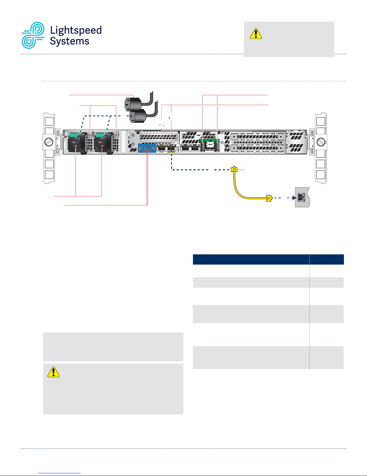
6A. Lightspeed Rocket Email Management - 1Gb Rear Panel Connections
USB Ports
Power Cords
Power Good LEDs
Power Good LEDs
AC Power
AC Power
Inlets
Inlets
Video Port
dsPower Cor
ideo PortV
Management
g
4
ID
ID
Auxilliary
illi
r
Port
Management
Port
POST ID
Ethernet
1
1
Ether
Cable
Cable
Cable
USB Ports
Network Interface Connectors
Network Interface Connectors
Network Interface Connectors
netEther
Local
Local
Area
Network
Network
2
eaAr
Step 1 Connect one end of the yellow Ethernet cable
into the Ethernet port labeled MANAGEMENT.
Step 2 Connect the other end of the yellow Ethernet
cable into an available switch port on your Local
Area Network. This port will require Internet
access.
Step 3 Please review the latest Lightspeed Systems
Rocket Email Management Product Manual on
the Lightspeed Systems Community Site at
(
http://community.lightspeedsystems.com/
product-information/documentation/
email-management/
).
Step 4 Connect the power cords.
Step 5 Proceed to Front Panel Operation on page 13.
NOTE: The server offers redundant, hot-swap capability. The connections
to AC mains should be made in a manner appropriate to local code and
consistent with customer power distribution with or without redundant
sources.
CAUTION
The power supply is hot-swappable only when you have a server with
redundant power supplies installed. If you only have one power supply
installed, before removing or replacing the power supply, you must first
take the server out of service, turn off all peripheral devices connected to
the server, turn off the server by pressing the power button, and unplug the
AC power cord from the server or wall outlet.
Power Supply Status LED
There is a single bi-color Power Good LED on each power supply
module to indicate power supply status. The LED operation is
defined in the following table.
Power Supply Condition
Output ON and OK
No AC power to both power supplies
AC present / Only 5VSB on (PS off)
AC cord unplugged or AC power lost; with a second
power supply in parallel still with AC input power
Power supply warning events where the power
supply continues to operate; high temp, high power,
high current, slow fan
Power supply critical event causing a shutdown;
failure, Over Current Protection, Over Voltage
Protection, fan fail
In normal operation the Power Good LED on Power Supply Module 1
and Module 2 will be SOLID GREEN. If the power is down, both LEDs
will BLINK GREEN.
LED State
GREEN
OFF
1Hz Blinking
GREEN
AMBER
1Hz Blinking
AMBER
AMBER
Lightspeed Rocket Hardware Installation Guide 7
Page 8
e
t
Auxilliary
CAUTION
Slide rail/mounted equipment is not
to be used as a shelf or a work space.
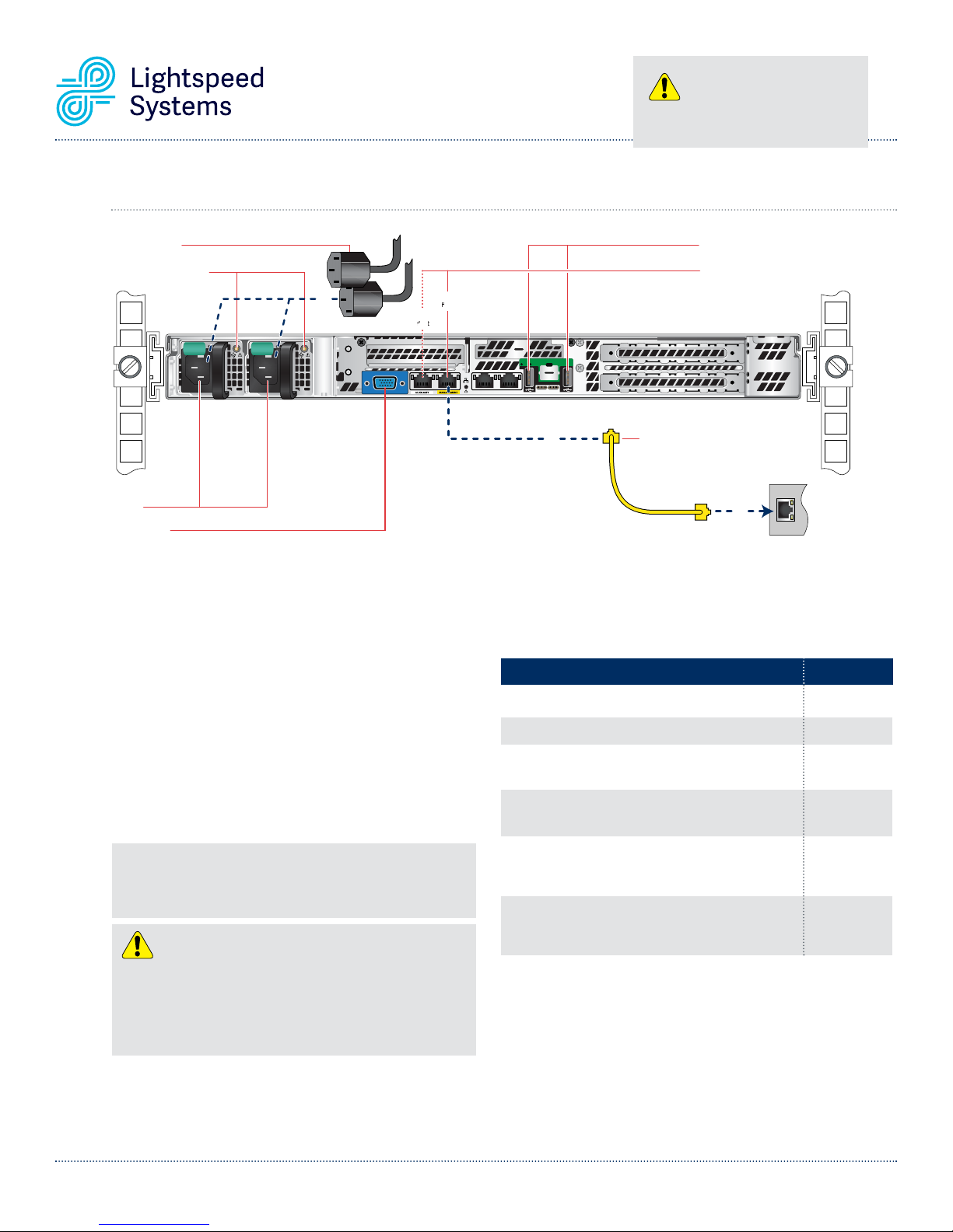
6B. Lightspeed Web Filter Policy Parent Rear Panel Connections
USB Ports
Power Cords
Power Good LEDs
Power Good LEDs
AC Power
AC Power
Inlets
Inlets
Video Port
dsPower Cor
ideo PortV
Management
g
4
ID
ID
Auxilliary
illi
r
Port
Management
Port
POST ID
Ethernet
1
1
Ether
Cable
Cable
Cable
USB Ports
Network Interface Connectors
Network Interface Connectors
Network Interface Connectors
netEther
2
Local
Local
Area
eaAr
Network
Network
Step 1 Connect one end of the yellow Ethernet cable
into the Ethernet port labeled MANAGEMENT.
Step 2 Connect the other end of the yellow Ethernet
cable into an available switch port on your Local
Area Network. This port will require Internet
access.
Step 3 Please review the latest Lightspeed Systems
Rocket Web Filter Product Manual on the
Lightspeed Systems Community Site at
(
http://community.lightspeedsystems.com/
product-information/documentation/web-filter/
Step 4 Connect the power cords.
Step 5 Proceed to Front Panel Operation on page 13.
NOTE: The server offers redundant, hot-swap capability. The connections
to AC mains should be made in a manner appropriate to local code and
consistent with customer power distribution with or without redundant
sources.
CAUTION
The power supply is hot-swappable only when you have a server with
redundant power supplies installed. If you only have one power supply
installed, before removing or replacing the power supply, you must first
take the server out of service, turn off all peripheral devices connected to
the server, turn off the server by pressing the power button, and unplug the
AC power cord from the server or wall outlet.
Power Supply Status LED
There is a single bi-color Power Good LED on each power supply
module to indicate power supply status. The LED operation is
defined in the following table.
Power Supply Condition
Output ON and OK
No AC power to both power supplies
).
AC present / Only 5VSB on (PS off)
AC cord unplugged or AC power lost; with a second
power supply in parallel still with AC input power
Power supply warning events where the power
supply continues to operate; high temp, high power,
high current, slow fan
Power supply critical event causing a shutdown;
failure, Over Current Protection, Over Voltage
Protection, fan fail
In normal operation the Power Good LED on Power Supply Module 1
and Module 2 will be SOLID GREEN. If the power is down, both LEDs
will BLINK GREEN.
LED State
GREEN
OFF
1Hz Blinking
GREEN
AMBER
1Hz Blinking
AMBER
AMBER
Lightspeed Rocket Hardware Installation Guide 8
Page 9
Auxilliary
CAUTION
Slide rail/mounted equipment is not
to be used as a shelf or a work space.
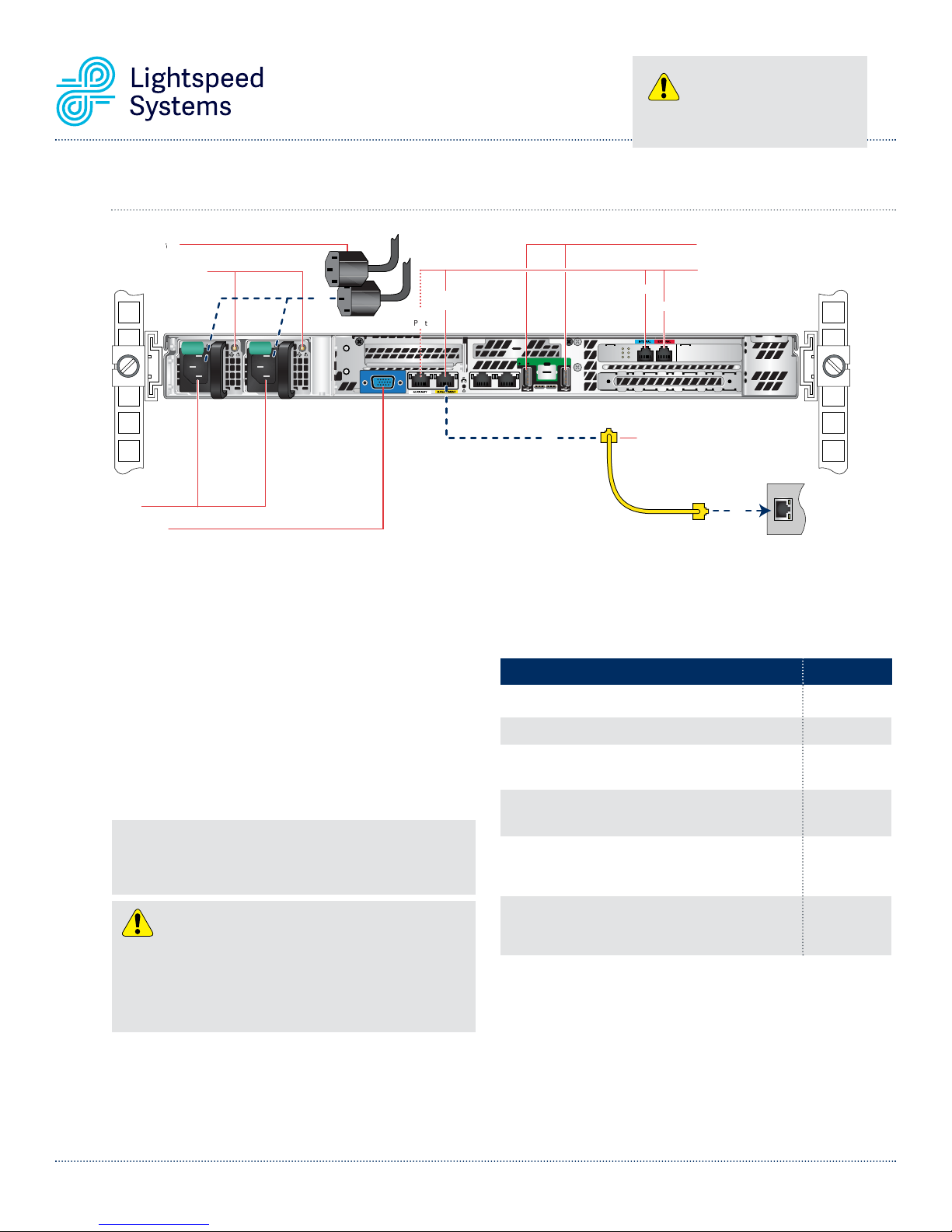
6C. Lightspeed Rocket Web Filter - 1Gb Rear Panel Connections
USB Ports
Power Cords
Power Good LEDs
Power Good LEDs
AC Power
AC Power
Inlets
Inlets
ideo PortV
Video Port
Internal
nal
Management
4
ID
ID
Auxilliary
illi
Port
Management
Port
POST ID
1
1
nal
External
Exter
Ethernet
Ether
Cable
Cable
Cable
USB Ports
Network Interface Connectors
Network Interface Connectors
Network Interface Connectors
nal
netEther
2
Local
Local
Area
eaAr
Network
Network
Step 1 Connect one end of the yellow Ethernet cable into
the Ethernet port labeled MANAGEMENT.
Step 2 Connect the other end of the yellow Ethernet cable
into an available switch port on your Local Area
Network. This port will require Internet access.
Step 3 Please review the latest Lightspeed Systems
Rocket Web Filter Product Manual on the
Lightspeed Systems Community Site at
(
http://community.lightspeedsystems.com/
product-information/documentation/web-filter/
).
Step 4 Connect the power cords.
Step 5 Proceed to Front Panel Operation on page 13.
NOTE: The server offers redundant, hot-swap capability. The connections
to AC mains should be made in a manner appropriate to local code and
consistent with customer power distribution with or without redundant
sources.
CAUTION
The power supply is hot-swappable only when you have a server with
redundant power supplies installed. If you only have one power supply
installed, before removing or replacing the power supply, you must first
take the server out of service, turn off all peripheral devices connected to
the server, turn off the server by pressing the power button, and unplug the
AC power cord from the server or wall outlet.
Power Supply Status LED
There is a single bi-color Power Good LED on each power supply
module to indicate power supply status. The LED operation is
defined in the following table.
Power Supply Condition
Output ON and OK
No AC power to both power supplies
AC present / Only 5VSB on (PS off)
AC cord unplugged or AC power lost; with a second
power supply in parallel still with AC input power
Power supply warning events where the power
supply continues to operate; high temp, high power,
high current, slow fan
Power supply critical event causing a shutdown;
failure, Over Current Protection, Over Voltage
Protection, fan fail
In normal operation the Power Good LED on Power Supply Module 1
and Module 2 will be SOLID GREEN. If the power is down, both LEDs
will BLINK GREEN.
LED State
GREEN
OFF
1Hz Blinking
GREEN
AMBER
1Hz Blinking
AMBER
AMBER
Lightspeed Rocket Hardware Installation Guide 9
Page 10
Auxilliary
CAUTION
Slide rail/mounted equipment is not
to be used as a shelf or a work space.
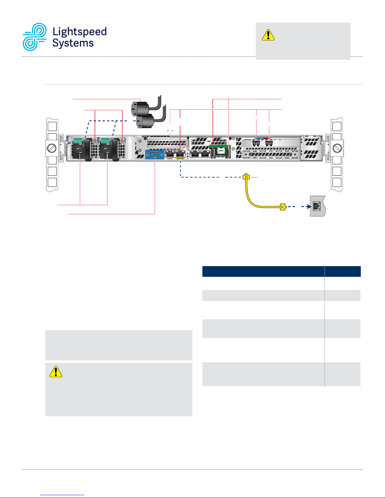
6D. Lightspeed Rocket Web Filter - 1Gb Fiber Rear Panel Connections
USB Ports
Power Cords
Power Good LEDs
Power Good LEDs
AC Power
AC Power
Inlets
Inlets
Video Port
ideo PortV
Internal
ernal
Management
4
ID
ID
Auxilliary
illi
Port
Management
Port
POST ID
1
1
nt
Ethernet
Ether
Cable
Cable
Cable
External
Exter
USB Ports
Network Interface Connectors
Network Interface Connectors
Network Interface Connectors
nal
netEther
Local
Local
Area
Network
Network
2
eaAr
Step 1 Connect one end of the yellow Ethernet cable into
the Ethernet port labeled MANAGEMENT.
Step 2 Connect the other end of the yellow Ethernet cable
into an available switch port on your Local Area
Network. This port will require Internet access.
Step 3 Please review the latest Lightspeed Systems
Rocket Web Filter Product Manual on the
Lightspeed Systems Community Site at
(
http://community.lightspeedsystems.com/
product-information/documentation/web-filter/
).
Step 4 Connect the power cords.
Step 5 Proceed to Front Panel Operation on page 13.
NOTE: The server offers redundant, hot-swap capability. The connections
to AC mains should be made in a manner appropriate to local code and
consistent with customer power distribution with or without redundant
sources.
CAUTION
The power supply is hot-swappable only when you have a server with
redundant power supplies installed. If you only have one power supply
installed, before removing or replacing the power supply, you must first
take the server out of service, turn off all peripheral devices connected to
the server, turn off the server by pressing the power button, and unplug the
AC power cord from the server or wall outlet.
Power Supply Status LED
There is a single bi-color Power Good LED on each power supply
module to indicate power supply status. The LED operation is
defined in the following table.
Power Supply Condition
Output ON and OK
No AC power to both power supplies
AC present / Only 5VSB on (PS off)
AC cord unplugged or AC power lost; with a second
power supply in parallel still with AC input power
Power supply warning events where the power
supply continues to operate; high temp, high power,
high current, slow fan
Power supply critical event causing a shutdown;
failure, Over Current Protection, Over Voltage
Protection, fan fail
In normal operation the Power Good LED on Power Supply Module 1
and Module 2 will be SOLID GREEN. If the power is down, both LEDs
will BLINK GREEN.
LED State
GREEN
OFF
1Hz Blinking
GREEN
AMBER
1Hz Blinking
AMBER
AMBER
Lightspeed Rocket Hardware Installation Guide 10
Page 11
i
Auxilliary
CAUTION
Slide rail/mounted equipment is not
to be used as a shelf or a work space.
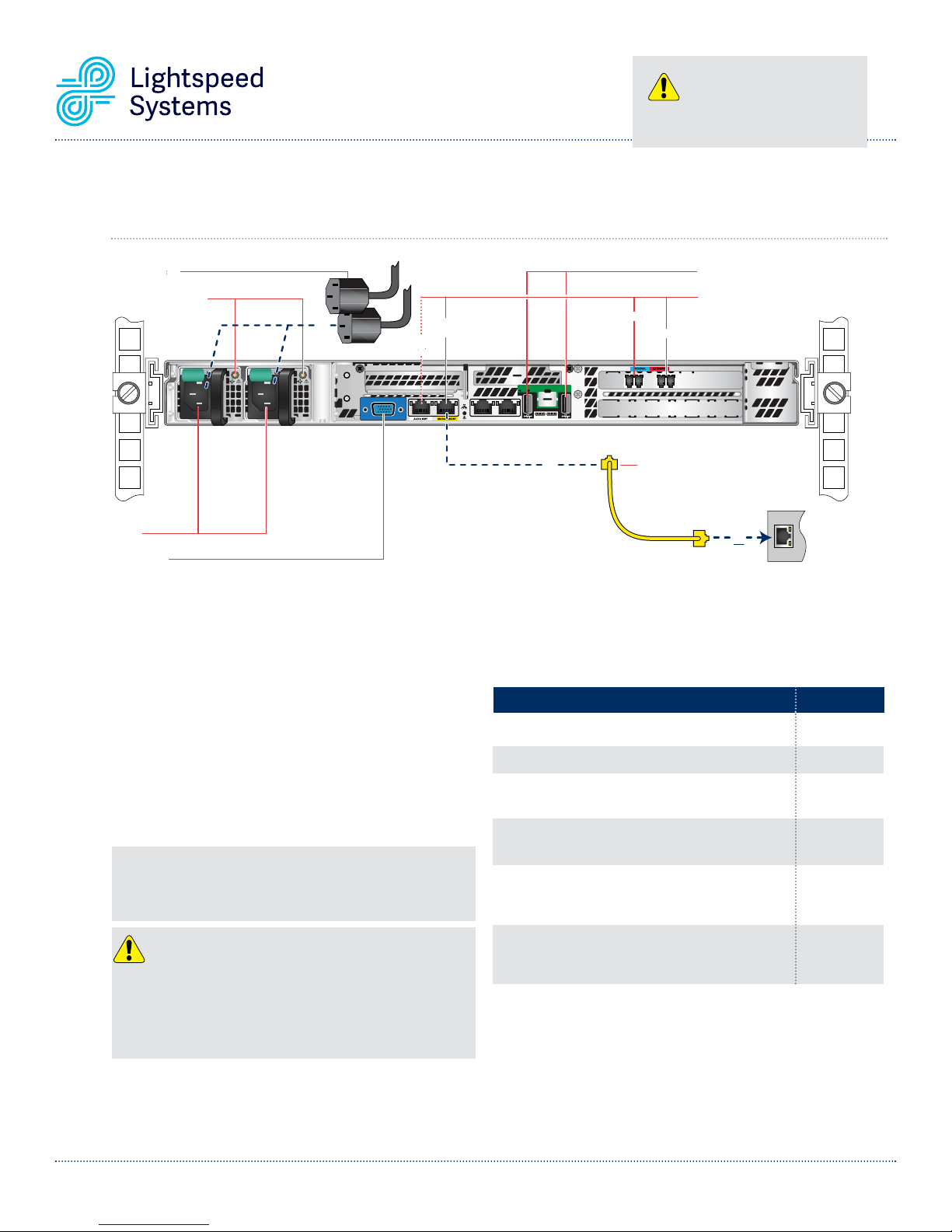
6E. Lightspeed Rocket Web Filter and Traffic Bridge - 10Gb Fiber
Rear Panel Connections
Power Cords
Power Good LEDs
Power Good LEDs
Management
Auxilliary
ill
Port
Management
Port
AC Power
AC Power
Inlets
Inlets
ideo PortV
Video Port
4
ID
ID
Step 1 Connect one end of the yellow Ethernet cable into
the Ethernet port labeled MANAGEMENT.
Step 2 Connect the other end of the yellow Ethernet cable
into an available switch port on your Local Area
Network. This port will require Internet access.
Step 3 Please review the latest Lightspeed Systems
Rocket Web Filter Product Manual on the
Lightspeed Systems Community Site at
(
http://community.lightspeedsystems.com/
product-information/documentation/web-filter/
).
Step 4 Connect the power cords.
Step 5 Proceed to Front Panel Operation on page 13.
NOTE: The server offers redundant, hot-swap capability. The connections
to AC mains should be made in a manner appropriate to local code and
consistent with customer power distribution with or without redundant
sources.
USB Ports
USB Ports
Network Interface Connectors
Network Interface Connectors
Network Interface Connectors
Internal
alernt
External
Exter
ernal
POST ID
Ethernet
Ether
1
1
Cable
Cable
Cable
netEther
Local
Local
Area
eaAr
Network
Network
2
Power Supply Status LED
There is a single bi-color Power Good LED on each power supply
module to indicate power supply status. The LED operation is
defined in the following table.
Power Supply Condition
Output ON and OK
No AC power to both power supplies
AC present / Only 5VSB on (PS off)
AC cord unplugged or AC power lost; with a second
power supply in parallel still with AC input power
Power supply warning events where the power
supply continues to operate; high temp, high power,
high current, slow fan
LED State
GREEN
OFF
1Hz Blinking
GREEN
AMBER
1Hz Blinking
AMBER
CAUTION
The power supply is hot-swappable only when you have a server with
redundant power supplies installed. If you only have one power supply
installed, before removing or replacing the power supply, you must first
take the server out of service, turn off all peripheral devices connected to
the server, turn off the server by pressing the power button, and unplug the
AC power cord from the server or wall outlet.
Lightspeed Rocket Hardware Installation Guide 11
Power supply critical event causing a shutdown;
failure, Over Current Protection, Over Voltage
AMBER
Protection, fan fail
In normal operation the Power Good LED on Power Supply Module 1
and Module 2 will be SOLID GREEN. If the power is down, both LEDs
will BLINK GREEN.
Page 12
Auxilliary
e
te
CAUTION
Slide rail/mounted equipment is not
to be used as a shelf or a work space.
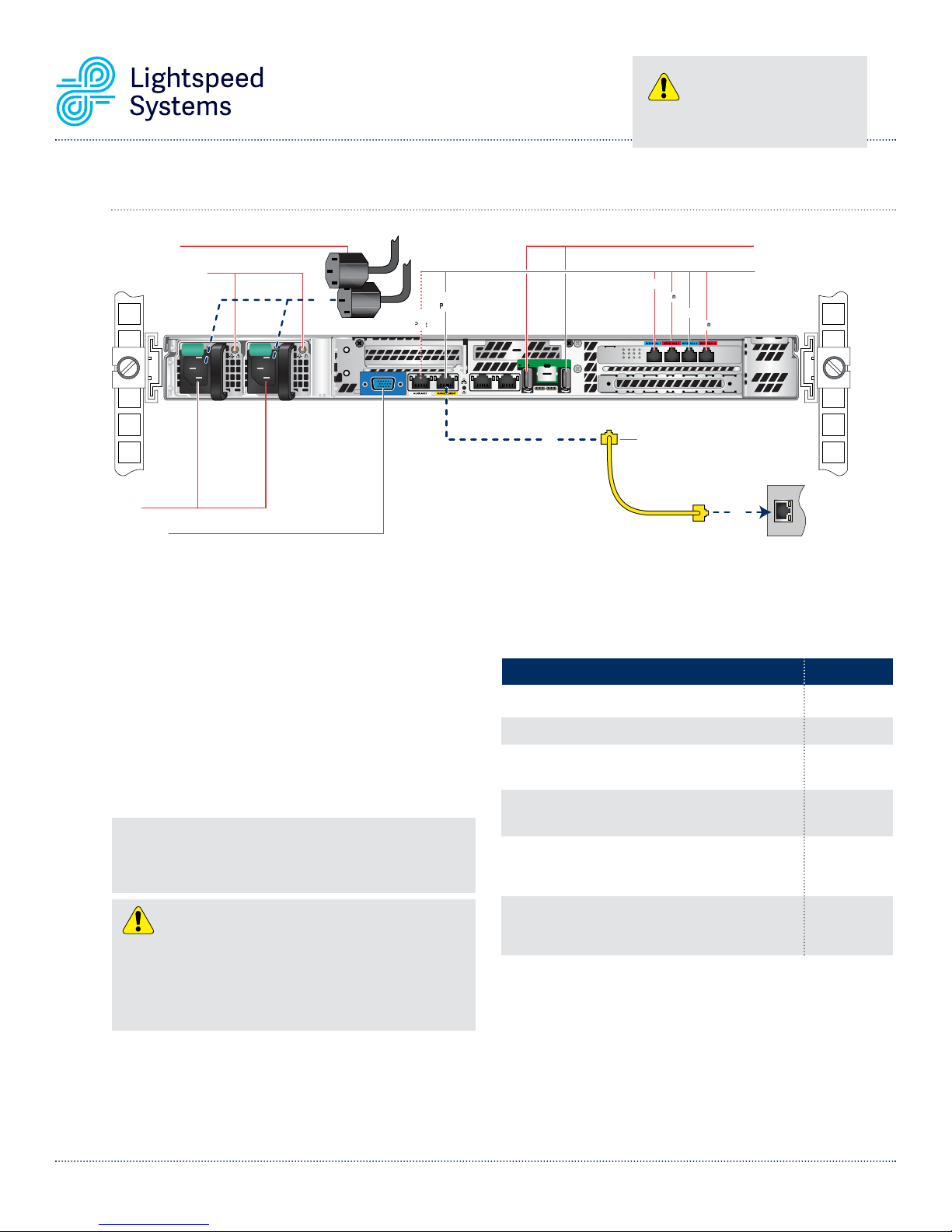
6F. Lightspeed Rocket Web Filter - Dual Bridge 1Gb Rear Panel Connections
USB Ports
Power Cords
Power Good LEDs
Power Good LEDs
AC Power
AC Power
Inlets
Inlets
Video Port
dsPower Cor
ideo PortV
Internal 1
nal 1
nt
1
Management
4
ID
ID
Auxilliary
illi
Port
Management
Port
POST ID
1
1
External 1
Ethernet
Ether
netEther
Cable
Cable
Cable
Internal 0
External 0
0n
USB Ports
Network Interface
Network Interface
Connectors
Connectors
Local
Local
Area
eaAr
Network
Network
2
Step 1 Connect one end of the yellow Ethernet cable into
the Ethernet port labeled MANAGEMENT.
Step 2 Connect the other end of the yellow Ethernet cable
into an available switch port on your Local Area
Network. This port will require Internet access.
Step 3 Please review the latest Lightspeed Systems
Rocket Web Filter Product Manual on the
Lightspeed Systems Community Site at
(
http://community.lightspeedsystems.com/
product-information/documentation/web-filter/).
Step 4 Connect the power cords.
Step 5 Proceed to Front Panel Operation on page 13.
NOTE: The server offers redundant, hot-swap capability. The connections
to AC mains should be made in a manner appropriate to local code and
consistent with customer power distribution with or without redundant
sources.
CAUTION
The power supply is hot-swappable only when you have a server with
redundant power supplies installed. If you only have one power supply
installed, before removing or replacing the power supply, you must first
take the server out of service, turn off all peripheral devices connected to
the server, turn off the server by pressing the power button, and unplug the
AC power cord from the server or wall outlet.
Power Supply Status LED
There is a single bi-color Power Good LED on each power supply
module to indicate power supply status. The LED operation is
defined in the following table.
Power Supply Condition
Output ON and OK
No AC power to both power supplies
AC present / Only 5VSB on (PS off)
AC cord unplugged or AC power lost; with a second
power supply in parallel still with AC input power
Power supply warning events where the power
supply continues to operate; high temp, high power,
high current, slow fan
Power supply critical event causing a shutdown;
failure, Over Current Protection, Over Voltage
Protection, fan fail
In normal operation the Power Good LED on Power Supply Module 1
and Module 2 will be SOLID GREEN. If the power is down, both LEDs
will BLINK GREEN.
LED State
GREEN
OFF
1Hz Blinking
GREEN
AMBER
1Hz Blinking
AMBER
AMBER
Lightspeed Rocket Hardware Installation Guide 12
Page 13
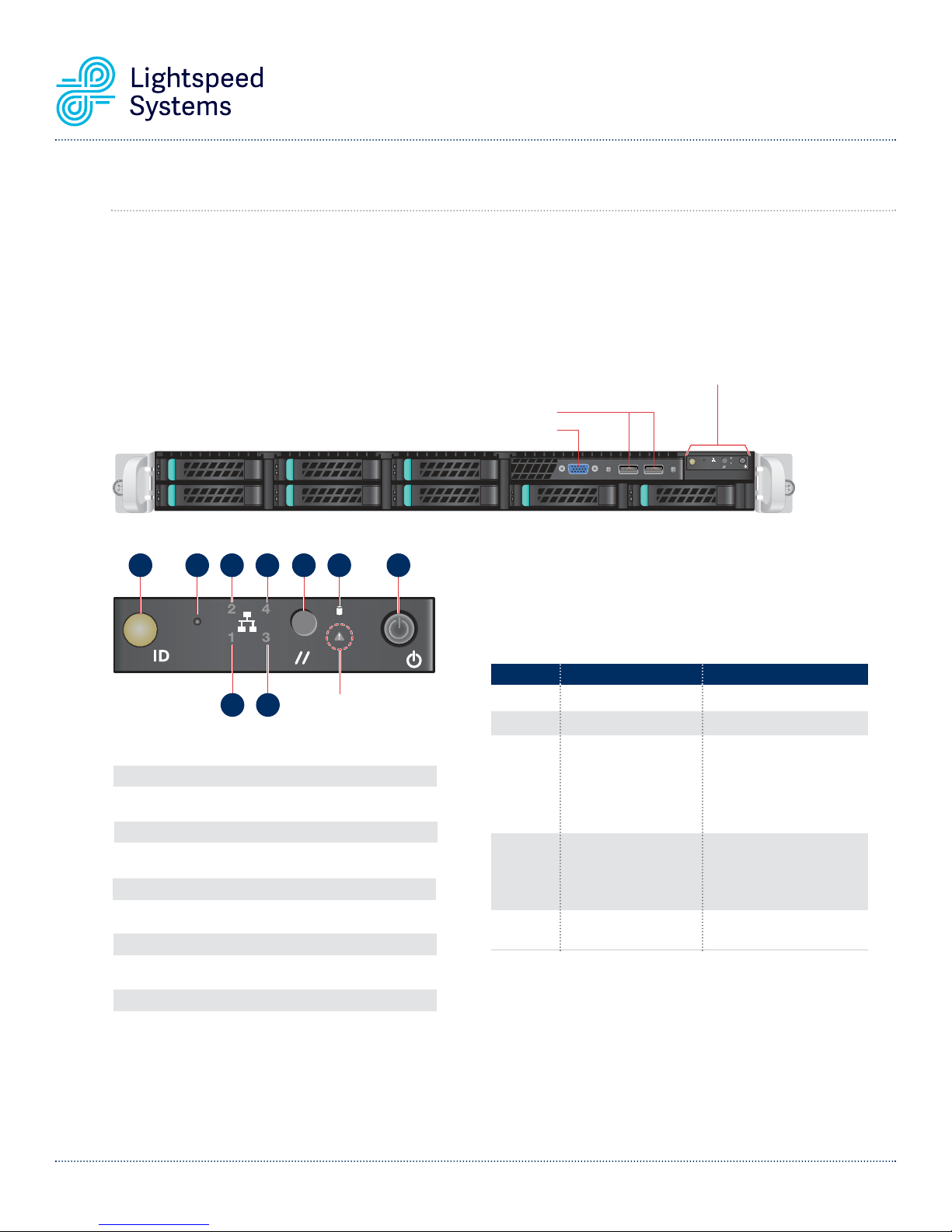
7. Front Panel Operation
By powering on the appliance you agree to all terms and conditions included in the End User
License Agreement (EULA) located at
Power on the appliance
n
Press the power button located on the far right on the front side of the appliance.
A B C D E F G
ABCD
EF G
http://www.lightspeedsystems.com/eula/
See Detail Illustration and Chart
See Detail Illustration and Chart
See Detail Illustration and Chart
for Fr
for Front Panel Information
USB Ports
USB Ports
ideo PortV
Video Port
System Status LED
There is a bi-color (Green/Amber) LED on the Front Panel (shown on
the left). The LED operation is defined in the following table.
mation ont Panel Inforfor Fr
4
123
ID
H I
HI
System
System
Status LED
Status LED
A System ID Button with integrated LED
B NMI Button (recessed, tool required for use)
C NIC 2 Activity LED
D NIC 4 Activity LED
E System Cold Reset Button
F Hard Drive Activity LED
G Power Button with integrated LED
H NIC 1 Activity LED
I NIC 3 Activity LED
LED Color
OFF
GREEN
GREEN
AMBER
AMBER
System State
System is not operating
Solid - On
~1 Hz blinking
~1 Hz blinking
Solid - On
Criticality
Not ready
OK
Degraded - system is
operating in a degraded
state although still functional,
OR system is operating in a
redundant state but with an
impending failure warning
Non-critical - system is
operating in a degraded
state with an impending
failure warning, although
still functioning
Critical, non-recoverable system is halted
Lightspeed Rocket Hardware Installation Guide 13
Page 14
T
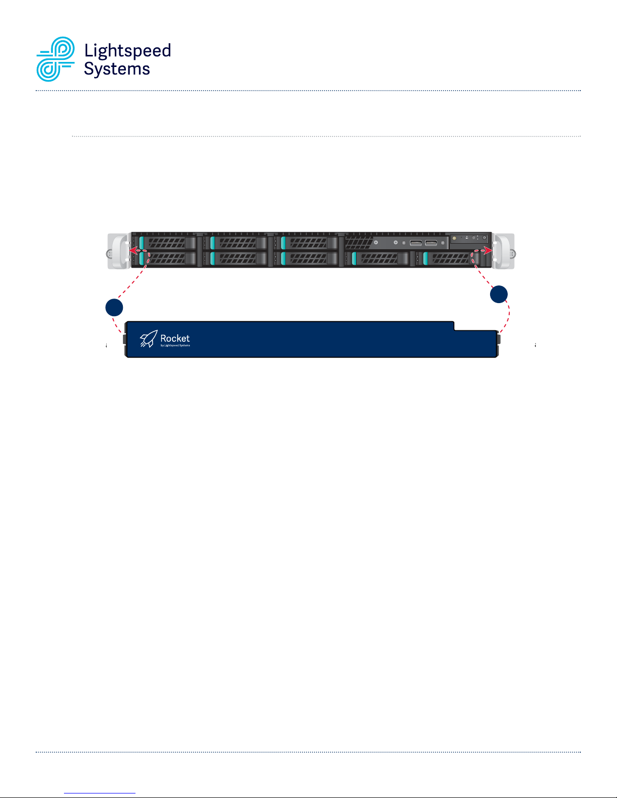
8. Bezel Installation on the Appliance
Step 1 Align the bezel with the front of the appliance. Insert the bezel tab on the right side of the bezel
into the handle on the right side of the appliance.
Step 2 Swing the left side of the bezel in toward the appliance. Press in on the bezel to engage the bezel tab
on the left side of the bezel into the handle on the left side of the appliance.
2
2
Left Flexible
Left Flexible
Bezel Tab
{
{
4
123
ID
1
1
Right Fixed
Right Fixed
{
{
Bezel Tab
zel
Lightspeed Rocket Hardware Installation Guide 14
Page 15

This page intentionally left blank
Lightspeed Rocket Hardware Installation Guide 15
Page 16
Lightspeed Systems
1800 19th Street
Bakersfield, CA 93301
Corporate Phone
Tel: 661.716.7600
Fax: 661.716.8600
Toll Free: 877.447.6244
Support: 800.444.9267
www.lightspeedsystems.com
Lightspeed Systems Europe:
Jubilee House
The Drive, Brentwood Essex CM13 3FR;
Reg No: 05336060 England and Wales
Tel: +44 (0) 1277 240 630
Fax: +44 (0) 1277 240 631
Copyright ©2014-2015 Lightspeed Systems, Inc. All rights reserved.
 Loading...