

Page 1
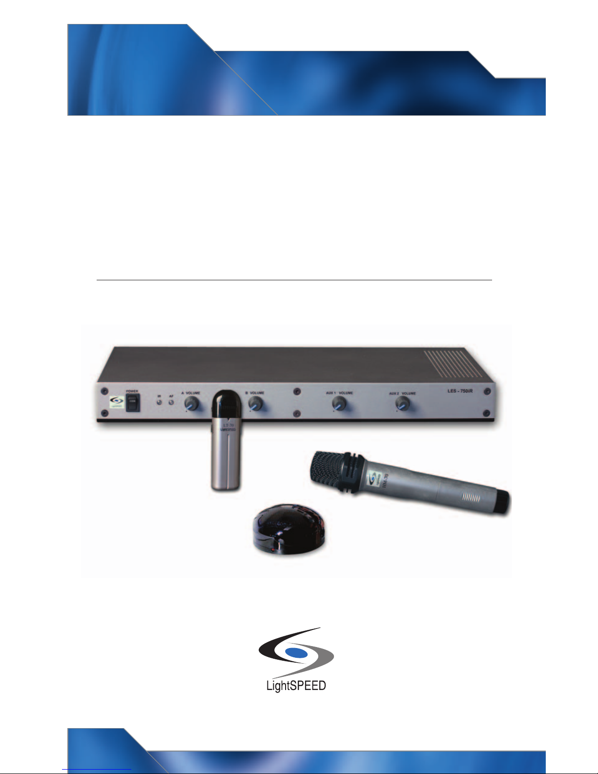
LightSPEED
LightSPEED
Page 2

Table of Contents
LES 750iR Infrared Classroom Amplification System:
Overview
LES 750iR System Components
System Installation:
1. Unpacking
2. Location
3. Speaker(s)
4. Receiver/Amplifier
5. IR Sensor Placement
a. Suspended Ceiling Mount
b. Wall or Solid Ceiling Mount
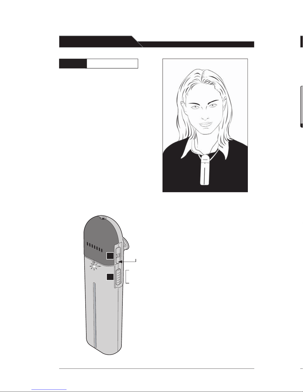
6. LightMic Microphone/Transmitter
7. Testing
LT-70 LightMic™ Microphone/Transmitter Controls and Connections
System Operation:
Step One: Powering the LES 750iR
Step Two: Charging the LightMic
Step Three: Operating the LightMic
Step Four: Adjusting the Volume
Step Five: Operating an Optional Second Microphone Simultaneously
Optional HM-70 Handheld Microphone Transmitter:
Overview
HM-70 Controls
Charging the HM-70
Operating the HM-70
Input from External Audio Equipment
Output to Personal FM Transmitter
Audio Equalizer
Front Panel Controls
Rear Panel Controls
Tips on Using Classroom Amplification
Five-year Limited Warranty to Original Purchaser
Troubleshooting Guide
Individual Components and Optional Accessories
Overall System Specifications
User Notes
1
2
3
3
3
3
4
4
4
5
5
6
8
9
10
1 1
12
12
13
14
1 5
16
17
18
19
7
16
19
20
2 1
22
23
Page 3
POWER
LES - 750I R
AUX 2 VOLUME
AUX 1 VOLUME
B VOLUME
A
VOLUME
IR AF
IR
AF
Overall System Specifications:
Carrier Frequencies (IR) 2.06/2.54 MHz
Frequency Stability +
Maximum Deviation
Dynamic Range > 73 dB
Signal-to-Noise Ratio
Frequency Response 40 Hz - 20 kHz (– 3 dB)
Receiver Specifications:
Receiver Type Superheterodyne
Receiver Sensitivity 6
Image and Spurious Rejection > 40 dB
Reception Selectivity 40 kHz
Squelching Threshold 3.2
Amplifier Specifications:
Power Output (System Total) 12 W per channel (48 W total)
Total Harmonic Distortion < 1% @ 20 W
Speaker Load Impedance 4 Ohms
Power Supply (UL Listed) 24 V/2.5 A
Dimensions 18 x 9 x 3 (H x W x D inches)
Weight 7 lbs.
Inputs:
TV/VCR RCA – Line Level
IR Sensors (2) “F” Connector
Outputs:
Auxiliary Outputs (2) 3.5 mm
Speaker Outputs (4) Binding Post Connectors
Transmitter Specifications:
Audio Distortion < 1%
Spurious Emissions < 30 dB
Built-in Microphone Uni-directional Electret
Battery Power (1-year warranty) 2 AA NiMH Rechargeable
Dimensions 1.4 x 1 x 4.6 (W x D x H inches)
Weight 3.04 oz (w/batteries)
External Sensor:
Power By Receiver Unit
Reception Coverage 360
Cable 50 ft., Plenum-rated Co-ax
Mounting Ceiling clip/Wall bracket
Diodes 32
LES 750iR Infrared Classroom Amplification System:
Overview
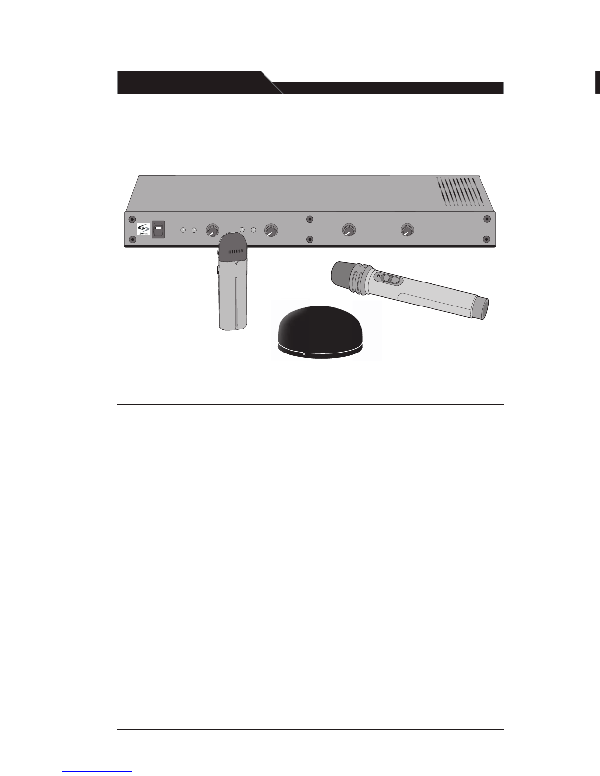
Congratulations on your purchase of the
LES 750iR Infrared Classroom Amplification
System! This simple, yet powerful technology provides crystal clear sound throughout the classroom, allowing every child to
hear every word every time.
As the teacher speaks into the LightMic
pendant-style microphone, his/her voice
is transmitted to the 750iR and then
amplified through the loudspeaker(s). The
standard system includes the LES 750iR
receiver/amplifier, LT-70 LightMic micro
phone/transmitter, SR70 infrared sensor
and speaker package.
The LES 750iR is a two-channel receiver
amplifier that allows the use of up to two
microphones simultaneously and up to
two additional audio input sources (such
as TV, VCR, DVD, CD, cassette, PC, LCD projector, etc.). In addition LightSPEED offers
various speaker options that are included
with your system to provide optimal
sound in rooms of all shapes and sizes.
The LT-70 LightMic is a wireless, pendantstyle microphone/transmitter. This two
channel, rechargeable unit is clipped to a
lavaliere cord and worn around the neck
for the teacher to use or can be used like a
standard handheld microphone for the
students to pass around when speaking.
LES 750iR Infrared Receiver/Amplifier
LT-70 LightMic™
Microphone/
Transmitter
SR-70 Infrared Sensor
HM-70 Handheld Microphone
(optional)
(The system also includes your choice of speaker package.)
[1]
Page 4
POWER
IR AF
A
VOLUME
B VOLUME
AUX 1 VOLUME
AUX 2 VOLUME
LES - 750I R
IR AF
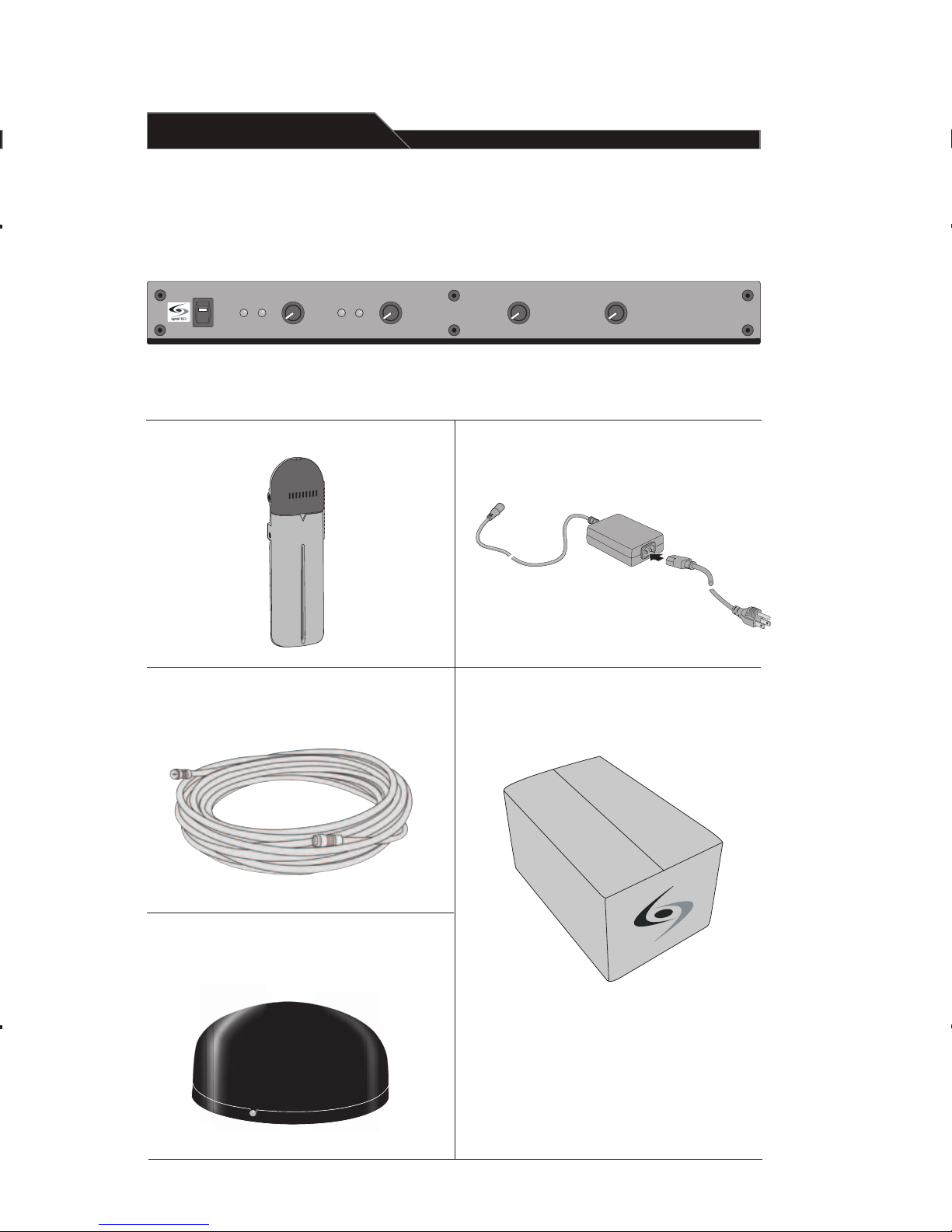
LES 750iR Classroom Amplification System Components:
Power Supply
SR-70 Infrared Sensor Cable
SR-70 Infrared Sensor
Various speakers are available
and are typically shipped in a
separate box with plenum-rated
speaker wire.
Speaker(s)
LES 750iR Receiver/Amplifier
LT-70 LightMic™
Microphone/
Transmitter
[2]
Page 5

System Installation
1. Unpacking Your System
• Ensure that you have received all
of the components of your system.
• Locate the speaker installation
instruction sheet that is packaged
with your speakers.
• Keep ALL packaging materials.
If the system must be returned,
it will be quick, convenient
and undamaged.
2. Location
Before installing the system, take
time to consider the placement of
your components.
• Infrared (IR) Sensor: Consider areas
of dark color in the room as they
reflect less infrared light. Sensor
mounting locations should be closer
to dark areas to improve reception.
• Receiver: Place on flat surface close
to standard electrical outlet.
• Speaker(s): Refer to the speaker
installation sheet that is in cluded with the speaker(s) for
placement needs.
• Speaker Wire and Sensor Wire:
Plenum wire is included for
each. Ensure the wire length will
cover the area from where you hang
the sensor and speaker(s) to where
you place the receiver. It’s optimal to
route wire overhead (above ceiling
tiles) if possible. In addition, wire
can be routed down the wall and
around the room perimeter secured
with heavy staples or wire raceway.
3. Speaker(s)
• Locate the speaker installation
instructions packed with
your speaker(s).
• Follow instructions and
mount speaker(s).
• Return to the LES 750iR manual to
complete the set up of your system.
4. Receiver/Amplifier
• Place the LES 750iR on a flat surface
like a bookcase or countertop.
• Ensure that the A VOLUME
and B VOLUME knobs are
turned all the way down (fully
counter-clockwise) and the POWER
switch is the OFF position.
• Verify the speaker wire(s) have
been inserted and secured into
the appropriate SPEAKER
OUTPUT connectors (refer to
your speaker instructions for
additional information).
• Plug the power cord into a standard
110 V electrical outlet and attach the
other end into the DC POWER jack
on the back of the LES 750iR.
• Switch the power on the front
panel to the ON position. The red
power indicator on the switch
will light.
Troubleshooting Guide
Please go through this checklist before
calling LightSPEED Service Department.
Battery Check:
• Confirm batteries are charged
each night. With proper charg-
ing, batteries will last about
one school year.
• Transmitters are charged via a
jumper cable from the back of the
LES 750iR. Make sure plugs are
secured and in the proper jacks.
• Confirm the green charging light
located on the front of the LightMic
is on while charging.
• Ensure the LightMic is turned off
while charging.
Hearing Static or Buzzing:
• If using two LightMics, check that
they are not set to the same
channel. If so, select a different
channel for one of the LightMics.
• Keep the LES 750iR at least 6 feet
away from computers.
Low Volume:
• Check volume level on the LES
750iR and adjust as necessary.
• Make sure the LightMic is positioned
properly around the neck (the top of
it should sit just below the collar-
bone). If the microphone is too far
away from the speaker’s mouth, it will
not properly pick up the voice.
Sound Fades In and Out (Drop Out):
• Test LightMic with fully charged
batteries. LED light on front of mic
will glow bright red.
[3]
Page 6
5. IR Sensor Placement
Sensor location is very important for
optimum performance of the LES 750iR
Classroom Amplification System.
• BEST: On the ceiling at or near the
middle of the classroom.
• GOOD: High and centered on the
long wall.
• AVOID: Locations in corners, on walls
at heights lower than 7 feet, or in
places where the line of site is or
could be obstructed.
• Other Considerations: Notice if there
are large areas of dark color (ie. black
boards or dark colored walls). Since
these dark color reflects less light, it
may be necessary to locate the sensor
near these areas.
• Connect the other end of the sensor
cable into either of the sensor inputs
on the back of the LES 750iR.
• Complete Step 7 (testing) to confirm
optimum sensor location, and perma nently secure sensor wire from the
sensor back to the receiver.
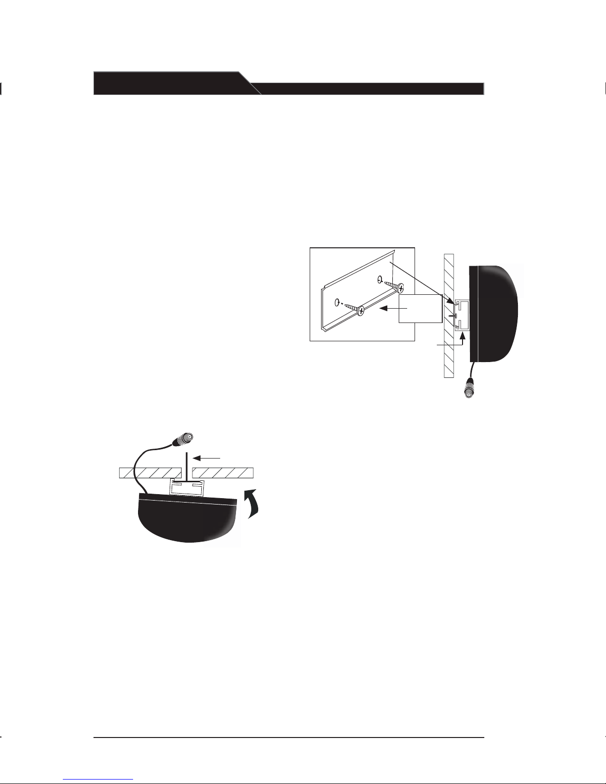
a. Suspended Ceiling Mount
• Lift the ceiling tile nearest the grid rail in
your desired sensor location. Guide one
side of the C-clip over one edge of the
grid rail. Providing firm support to the
back of the grid rail with one hand (to
prevent bending), firmly and carefully
snap the second side of the C-clip over
the edge of the rail.
• Uncoil sensor wire. Connect one end of
the sensor cable to the plug on the
sensor. Loosely secure wire overhead
and route it back to the receiver.
b. Wall or Solid Ceiling Mount
• Screw the plastic mounting
strip on to a place high on the
wall or in the middle of the solid
ceiling. Mount the strip horizontally
as shown above.
• Firmly snap the C-clip on the back
of the IR sensor onto the plastic
mounting strip with the sensor plug
hanging down (if a wall mount)
or toward the receiver location
(if ceiling mount).
• Uncoil the sensor wire. Connect one
end of the sensor cable to the plug
on the sensor. Loosely secure wire
overhead and route it back to
the LES 750iR.
• Connect the other end of the sensor
cable to either of the sensor inputs
on the back of the LES 750iR.
• Complete Step 7 (testing) to confirm
optimum sensor location and
permanently secure wire from the
sensor back to the LES 750iR.
-
[4]
ceiling grid rail
wall
mounting
strip
c-clip
sensor jack
Page 7
R
SENSOR
SHOR
T
SENSOR INPUTS
1K6 2
K5
6K3
4K
+10
0
-1
0
AUX
AUX
IN
1
IN
2
EQUALIZE
R
SENSOR
SHOR
T
SENSOR INPUTS
25
0
40
0
60
0
1K
1K6 2
K5
6K3
4K
+10
0
-1
0
DC POWER CHARGE
MIXED
AUDIO
OU
T
OU
T
ADJ
ADJ
AUX
AUX
IN
1
IN
2
ON
EQUALIZE
R
SENSOR
SHOR
T
SENSOR INPUTS
25
0
40
0
60
0
1K
1K6 2
K5
6K
3
4K
+10
0
-1
0
3
4
5
SPEAKER OUTPUT
DC POWER CHARGE
MIXED
AUDIO
OU
T
OU
T
ADJ
ADJ
AUX
AUX
IN
1
IN
2
OFF
ON
OFF
ON
OFF
ON
OFF
ON
1
2 3
4
EQUALIZE
R
SENSOR
SHOR
T
SENSOR INPUTS
25
0
40
0
60
0
1K
1K6 2
K5
6K
3
4K
+10
0
-1
0
1
2
1. SPEAKER OUTPUTS (1-4): These
binding post connectors are used to
connect the 750iR to the loudspeakers.
2. SPEAKER ON/OFF: These individual
speaker switches can be used
to turn off the audio in a specific area
of the classroom where there may be
a learning group or quiet time.
3. DC POWER: Plug the AC/DC power
supply into this jack.
4. CHARGE: These jacks charge the
LightMic(s) and optional handheld
microphone with the supplied
charging cable(s).
5. MIXED AUDIO OUT: These output
jacks send the processed audio signal
the external equipment such as a
recorder or an assistive listening
device like LightSPEED’s LES-370
Personal FM System.
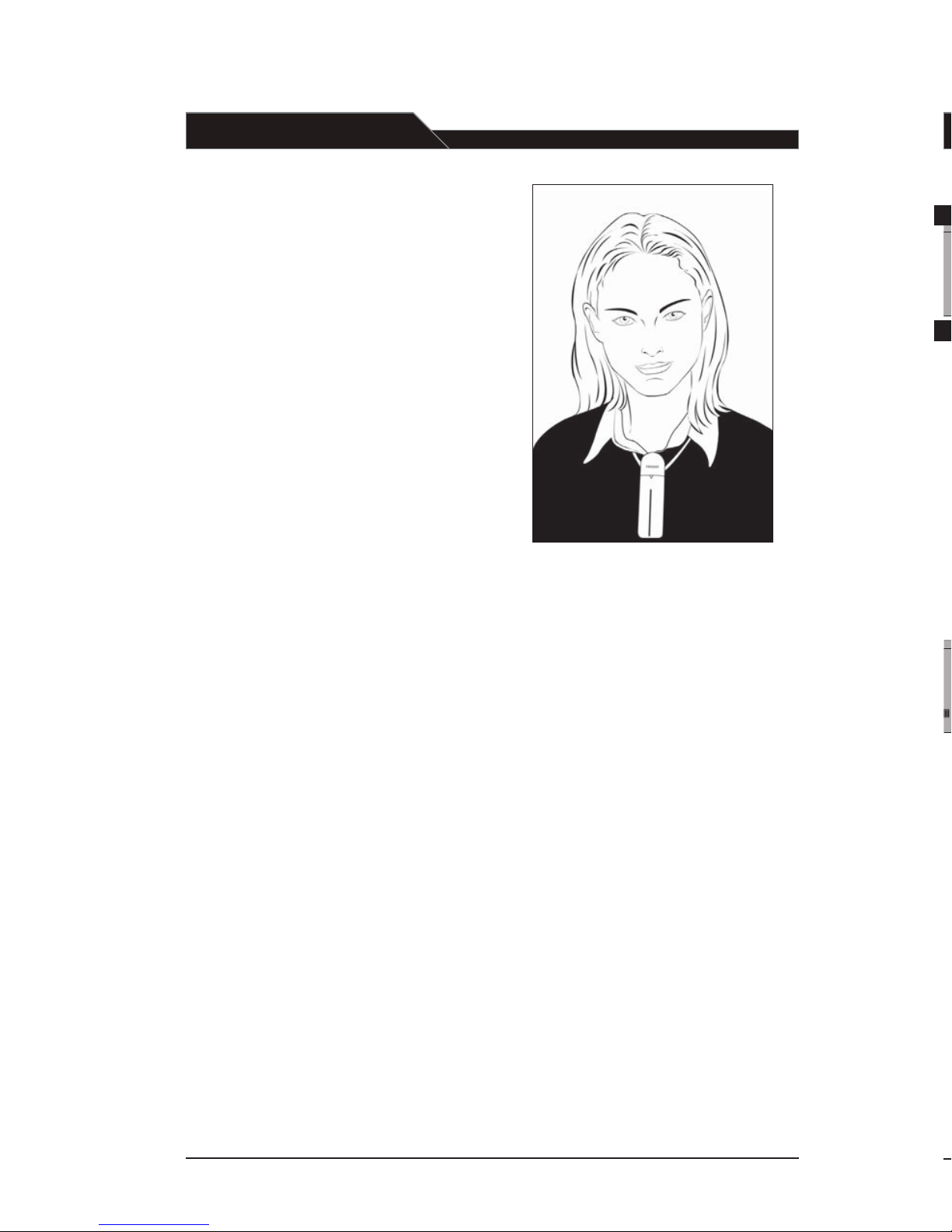
6. LightMic Microphone/Transmitter
For testing purposes, basic instructions
for wearing and operating the LightMic
are provided below. For more detailed
instructions, refer to page 11.
• Clip the LightMic to the
lavaliere cord.
• Place the LightMic and lavaliere cord
around your neck and adjust cord
length so the top of the LightMic
sits just below your collar bone.
• Slide the ON/OFF switch on the
LightMic to ON. The red power
indicator will light.
• Slide the channel select switch to “A.”
7. Testing
Test the system to ensure everything is
correctly connected and working
properly before your first full day of use.
A second person is helpful to listen and
ensure your voice is clear but not loud.
• With the LightMic positioned
properly around the neck, speak
normally and turn the A VOLUME
clockwise until an optimum voice
level is achieved. You may not be
able to hear your own voice when
this is properly set. However, your
students will.
[ note: ]
The system can generate feedback (a squeal
ing or howling sound) if there is too much
volume or the equalization (EQ) levels are
incorrectly set. Adjust the EQ level sliders
if necessary to eliminate feedback and to
obtain a natural sound.
• With volume and EQ levels set, walk
around the room, paying special
attention to the areas farthest from
the IR sensor. Your voice should
remain clear and intelligible.
Rear Panel Controls
[5]
Page 8
AUX 1 VOLUME
AUX 2 VOLUME
LES - 750IR
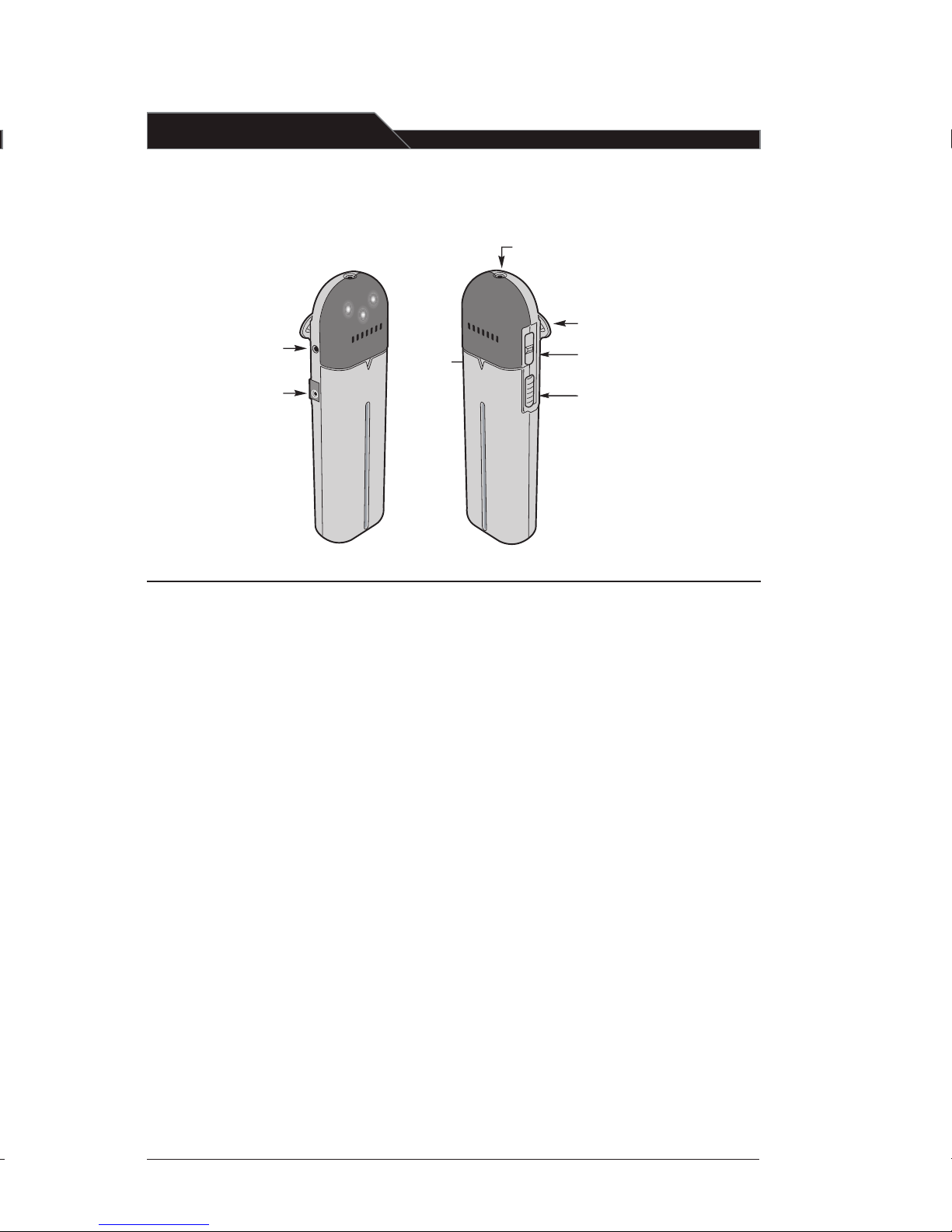
1. ON/OFF Switch: This switch,
located on the side of the LightMic,
turns the unit on or off. The red
triangle-shaped LED on the front
of the LightMic will light when
power is on.
2. Channel Select Switch (CH A/B):
This switch allows for selection
between Channel A or B. If you
are using a single microphone/
transmitter for your system, we
recommend using Channel A.
LT-70 LightMi
c
™
Microphone/Transmitter:
Controls and Connections
3. Power/Charge LED Indicator:
This triangle-shaped LED is two color. It glows red when the LightMic
is powered on, green when charging
and goes out when fully charged.
4. External Microphone Connector (MIC):
Use the 3.5 mm MIC jack for the
optional TK-250 headset microphone.
5. Charger Connector (CHARGER):
Use the jack labeled CHARGER to
connect the charging cable from the
LES 750iR to the LightMic for daily
battery recharging.
Clip
ON/OFF
Sw
itch
Channel
Select [A
-B]
Microphone
Power
LED
Charger
Co
nnector
External
Micr
ophone
Co
nnector
[6]
Page 9
1
2
RED
BLACK
POWER
IR AF
A VOLUME
B VOLUME
AUX 1 VOLUME
AUX 2 VOLUME
LES - 750I R
IR AF
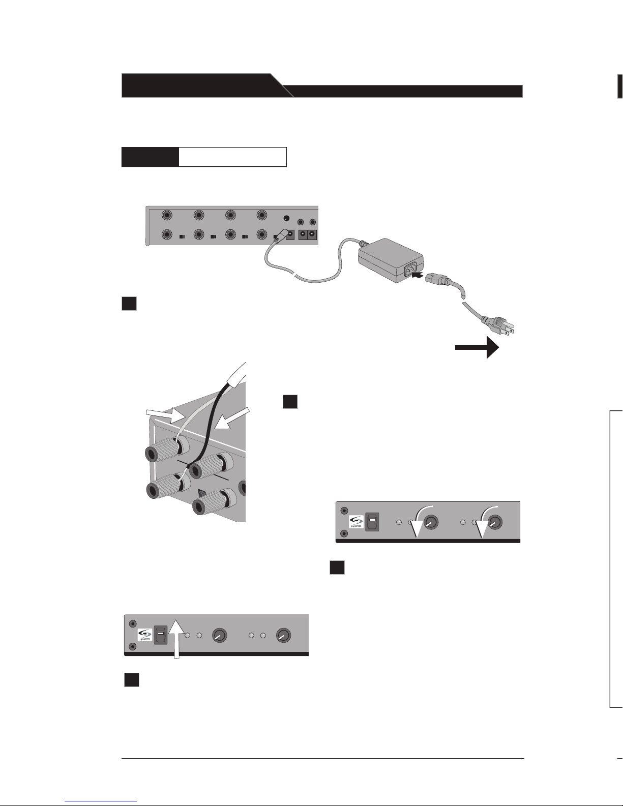
Check that the LES 750iR is connected to a power
source. Connect the power supply into a standard
AC outlet, and then plug the other end to the DC
POWER jack on the back panel.
SPEAKER OUTPUT
DC POWER CHARGE
MIXED
AUDIO
OUT
OUT
ADJ
ADJ
AUX
AUX
IN
1
IN
2
OFF
ON
OFF
ON
OFF
ON
OFF
ON
1
2 3
4
EQUALIZE
R
SENSOR
SHOR
T
SENSOR INPUTS
25
0
40
0
60
0
1K
1K6 2
K5
6K
3
4K
+10
0
-1
0
Audio Equalizer
The LES 750iR has a built-in 8-band
equalizer. This equalizer consists of eight
sliding controls that adjust the levels of
various high and low frequency sounds.
Because all loudspeakers and class-
rooms have different acoustical
properties, it can be difficult to
produce optimum sound
quality in every room. However,
this equalizer allows the installer to
fine tune the system, creating high
quality sound in every classroom
with any loudspeaker.
• The 8-band Equalizer is shipped from
the factory at preset levels based on
the speaker type. Refer to your speaker
install guide for more information on
these standard settings.
SPEAKER OUTPUT
DC POWER CHARGE
MIXED
AUDIO
OU
T
OU
T
ADJ
ADJ
AUX
AUX
IN
1
IN
2
OFF
ON
OFF
ON
OFF
ON
OFF
ON
1
2 3
4
EQUALIZE
R
SENSOR
SHOR
T
SENSOR INPUTS
25
0
40
0
600
1K
1K6 2
K5
6K
3
4K
+10
0
-1
0
Turn ON the power switch located
on the left side of the front panel
of the receiver. The red POWER
light on the switch will glow.
To AC outlet
System Operation:
Turn the volume controls
(A VOLUME and B VOLUME) on
the front panel are turned all the
way down (fully counter-clockwise).
Make sure the speakers are securely
connected to their binding posts (as
described in the speaker installation
instructions) and the speaker switches
are set to the ON position.
Step 1:
Powering the LES 750iR
POWER
IR AF
A
VOLUME
B VOLUME
AUX 1 VOLUME
AUX 2 VOLUME
LES - 750I R
IR AF
[7]
b
c
d
EQUALIZE
R
SENSOR
SHOR
T
SENSOR INPUTS
25
0
40
0
60
0
1K
1K6 2
K5
6K3
4K
+10
0
-1
0
a
Page 10
MIXED
AUDIO
OUT
OU
T
ADJ
AUX
AUX
IN
1
IN
2
EQUALIZE
R
SENSOR
SHOR
T
SENSOR INPUTS
25
0
40
0
60
0
1K
1K6 2
K5
6K
3
4K
+10
0
-1
0
Green
LED
However, do not leave the LightMic plugged
into the charger for more than 10 days, as it
will significantly shorten battery life.
6. Once the batteries are charged,
remove the charging cable from
the LightMic.
7. NiMH batteries will maintain their
charge for a full day of normal
classroom use.
8. With proper care, NiMH batteries
will provide service for at least one
year. If battery or charging problems
occur, contact LightSPEED Service
at 800.732.8999.
[ caution! ]
Do not attempt to charge alkaline
batteries—they can overheat and
expand, creating a significant
hazard and damaging the LightMic.
(This is not covered by the warranty.)
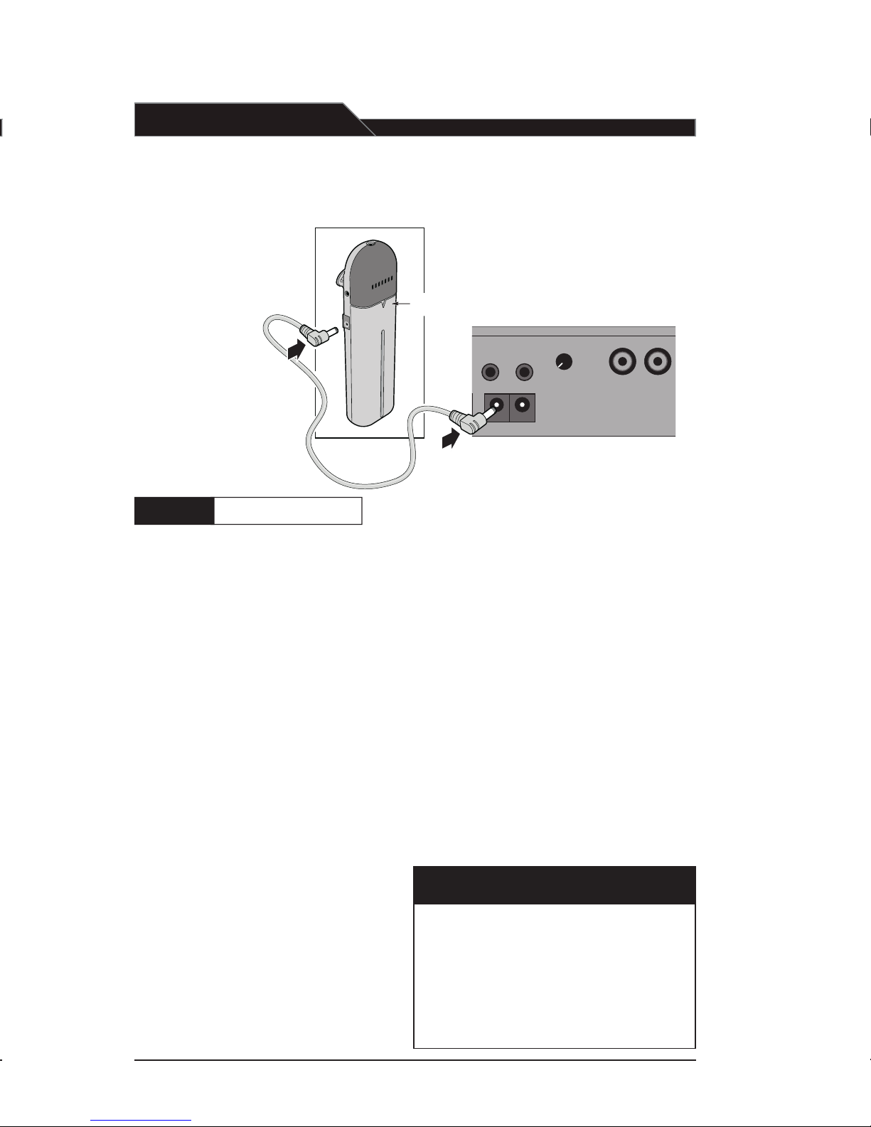
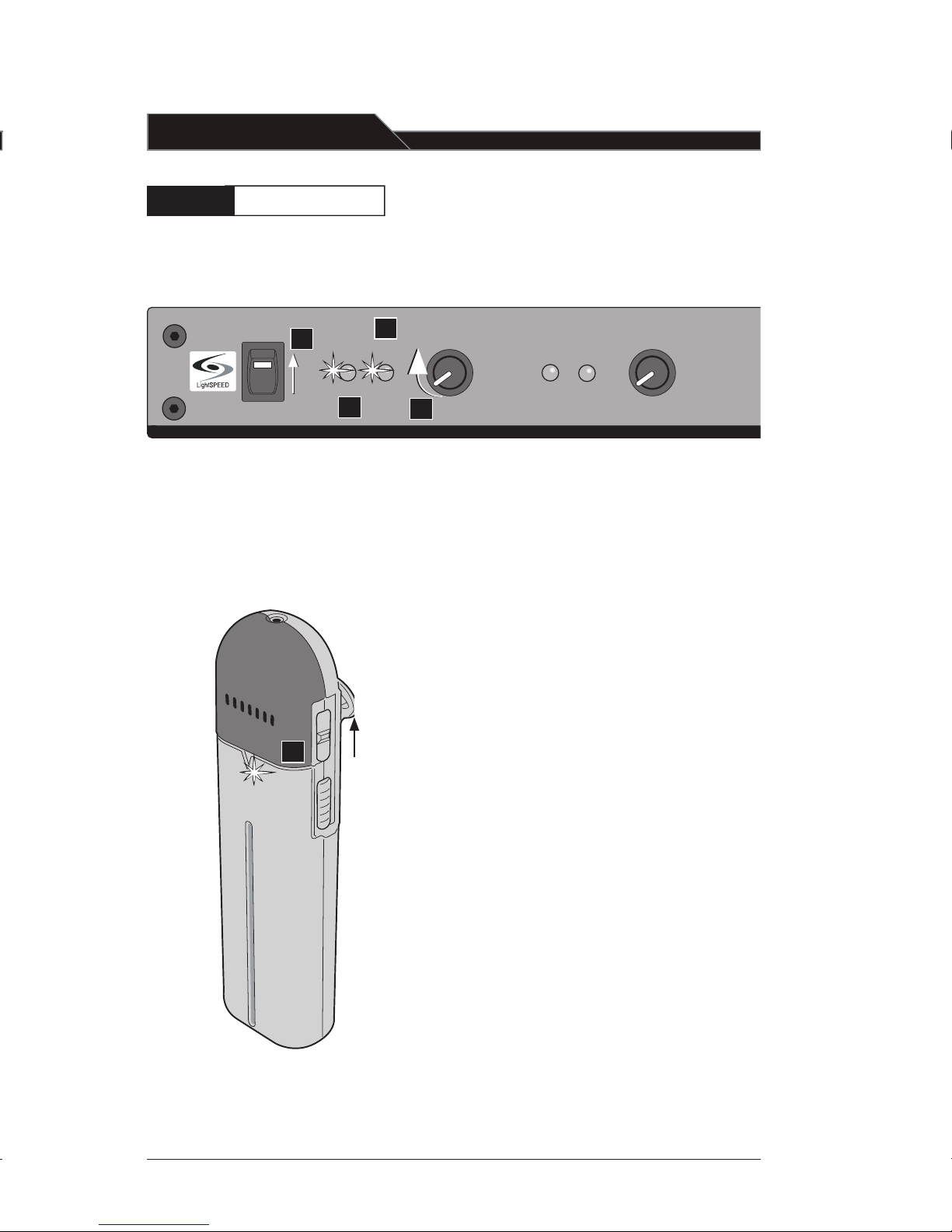
1. Ensure the LightMic is turned OFF.
The LES 750iR must be connected
to AC power in order to charge
the LightMic.
2. The LightMic’s rechargeable batteries
are factory installed. Plug one end of
the charging cable firmly into the
jack labeled CHARGER on the side of
the LightMic. Connect the other end
of the charging cable to one of the
MIC CHARGE jacks on the back of
the LES 750iR.
3. The triangle-shaped light on the
front of the LightMic transmitter
glows green when the cable is
connected and charging correctly.
The light goes out when fully charged.
4. The batteries will fully charge
in 8 to 12 hours.
5. It is best to leave the LightMic
charging until used, since the
batteries slowly lose their charge
when not in use.
The rechargeable NiMH
batteries must be fully
charged before regular
classroom operations.
Charging the LightMic
Step 2 :
[8]
Page 11
POWER
IR AF
A
VOLUME
B VOLUME
AUX 1 VOLUME
AUX 2 VOLUME
IR AF
The Channel A/B switch is located inside the
battery compartment. The switch is set to
Channel B at the factory.
1. Slide the power switch on the side of
the HM-70 all the way up. The power
indicator LED will glow red and stay on.
2. The center position of the power
switch is MUTE. When in this mode,
the HM-70 is transmitting a signal, but
no audio can be heard through the sys-
tem. This is useful if you wish to
temporarily turn audio off during a
private conversation.
3. Do not adjust the audio gain adjuster
that is located in the battery
compartment. It has been preset by
factory technicians and is not intended
as a volume control.
1. The LightMic has a built-in microphone.
Once the transmitter is switched on, the
microphone is activated.
2. The LightMic is typically worn around
the teacher’s neck as a hands free,
pendant-style microphone. Due to its
unique design, it can also be used as a
handheld microphone for student
pass-around use. For hands-free,
teacher use:
• Clip the LightMic to the supplied
lavaliere cord.
• Place the LightMic and cord around
your neck and adjust the len
gth so
the top of the LightMic sits just
below your collar bone.
ON/OFF
Switch
CH B
CH A
Step 3:
Operating the LightMic
3. On the side of the LightMic is the Chan nel select switch. Ensure the switch is in
the “A” position. (If a second LightMic
is used for simultaneous operation, set
one LightMic to Channel A and the
second LightMic to Channel B.)
4. Slide the ON/OFF switch on the side of
the LightMic to ON. The triangle shaped light on the front glows red,
indicating the microphone is charged
and ready for use.
5. The IR indicator to the left of the A
VOLUME control will light indicating
that the LES 750iR is receiving a signal
from the LightMic.
6. To turn the LightMic off, slide the
switch to the OFF position.
7. At the end of the day, make sure to plug
the microphone back into the charger
so it is ready to use the following day.
Channel Selection
3
4
Operating the HM-70
[9]
Page 12
POWER
IR AF
A
VOLUME
B VOLUME
AUX 1 VOLUME
AUX 2 VOLUME
IR AF
ON
1-a
2
1-c
3
ON
Adjusting the Volume
Step 4:
1. Make sure:
a. 750iR is switched ON.
b. LightMic is switched on and the
triangle-shaped is glowing red.
c. IR indicator on the 750iR is glowing
(to the left of A VOLUME).
2. As you speak into the microphone the
AF indicator light (to the left of A
VOLUME) on the 750iR will flash on
and off as the voice volume increases
and decreases.
3. While speaking at a normal level,
slowly turn the A VOLUME knob
clockwise to increase the volume of
the loudspeaker(s) until the sound
level is adequate for the room.
[note:]
Feedback or “squealing” may occur if the
volume is set too high. Reducing the loudness
of the speakers with the volume control
usually eliminates feedback.
ON
1-b
EQUALIZE
R
SENSOR
SHOR
T
SENSOR INPUTS
6K
3
4K
+10
0
-1
0
25
0
40
0
60
0
1K
1K6 2K5
Volume is set by adjusting the
volume control on the LES 750iR.
[10]
Page 13
POWER
IR AF
A VOLUME
B VOLUME
AUX 1 VOLUME
AUX 2 VOLUME
IR AF
GAIN
CHANNEL
A B
NiMH
Step 5:
CH. A
1-a
1-b
ON
CH. B
1-a
1-b
ON
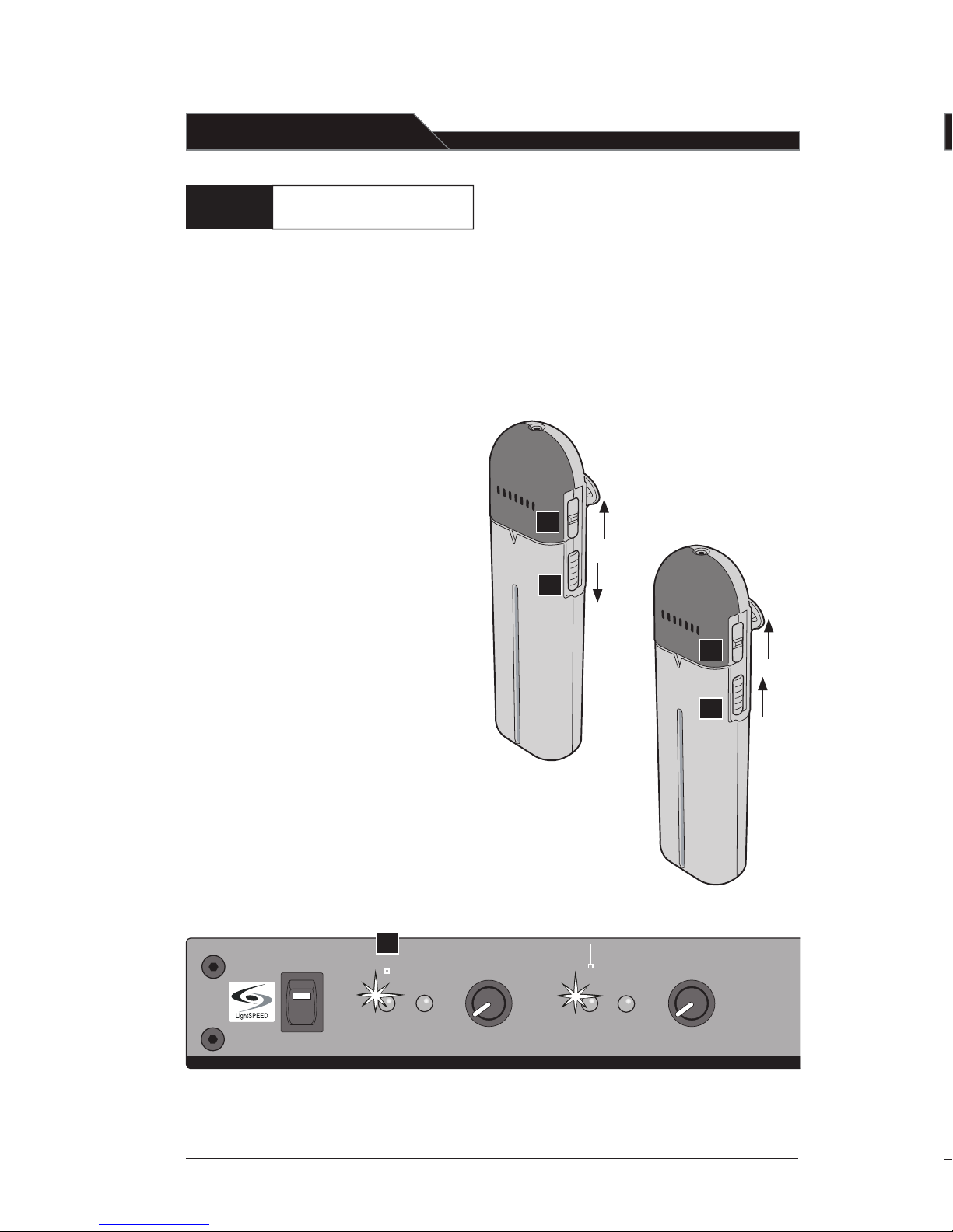
1. If you have two LightMics:
a. Set one LightMic to Channel A
and the other to Channel B using
the slide switch on the side of
the units.
b. Switch one of the microphones
ON and begin speaking normally.
Adjust the volume accordingly.
Repeat with the second
microphone.
c. Notice when both LightMics
are ON, the two IR indicator
lights on the front panel of
the LES 750iR will glow. As
you speak into the LightMics,
both AF lights will blink.
1-c
ON
The LES 750iR has two independent receivers: Channel A and B.
This makes it possible to operate two microphones simultaneously.
Follow the instructions below when using a second microphone:
HM-70 Controls
1. Power Switch: This 3-position
switch allows you to turn the
microphone on (up position),
mute the microphone
(middle position), and
turn off the microphone
(down position). The red LED
above the switch lights when the
switch is in the “mute” or power
“on” positions.
2. Channel Select Switch:
This switch allows you to
choose between Channel
A or Channel B. This switch
is set to Channel B at the factory.
3. Power/Charge LED Indicator:
This two-color LED indicator
is located directly above the
power switch. It glows red
when the HM-70 is
powered on and glows
green when charging.
4. Charger: Use this jack to
connect the charging cable
from the 780iR to the HM-70 for
daily battery recharging.
Optional HM-70 Handheld
Microphone/Transmitter:
Overview
The HM-70 handheld microphone is
an optional component that can be
ordered with the LES 750iR system.
This microphone is typically passed
around among students, so that
when they are asking a question or
reading aloud, all the other children
can clearly hear every spoken word.
Operating an Optional Second
Microphone Simultaneously
[11]
Page 14
AUX 1 VOLUME
AUX 2 VOLUME
LES - 750IR
GAIN
CHANNEL
A B
NiMH
HM-70 Controls
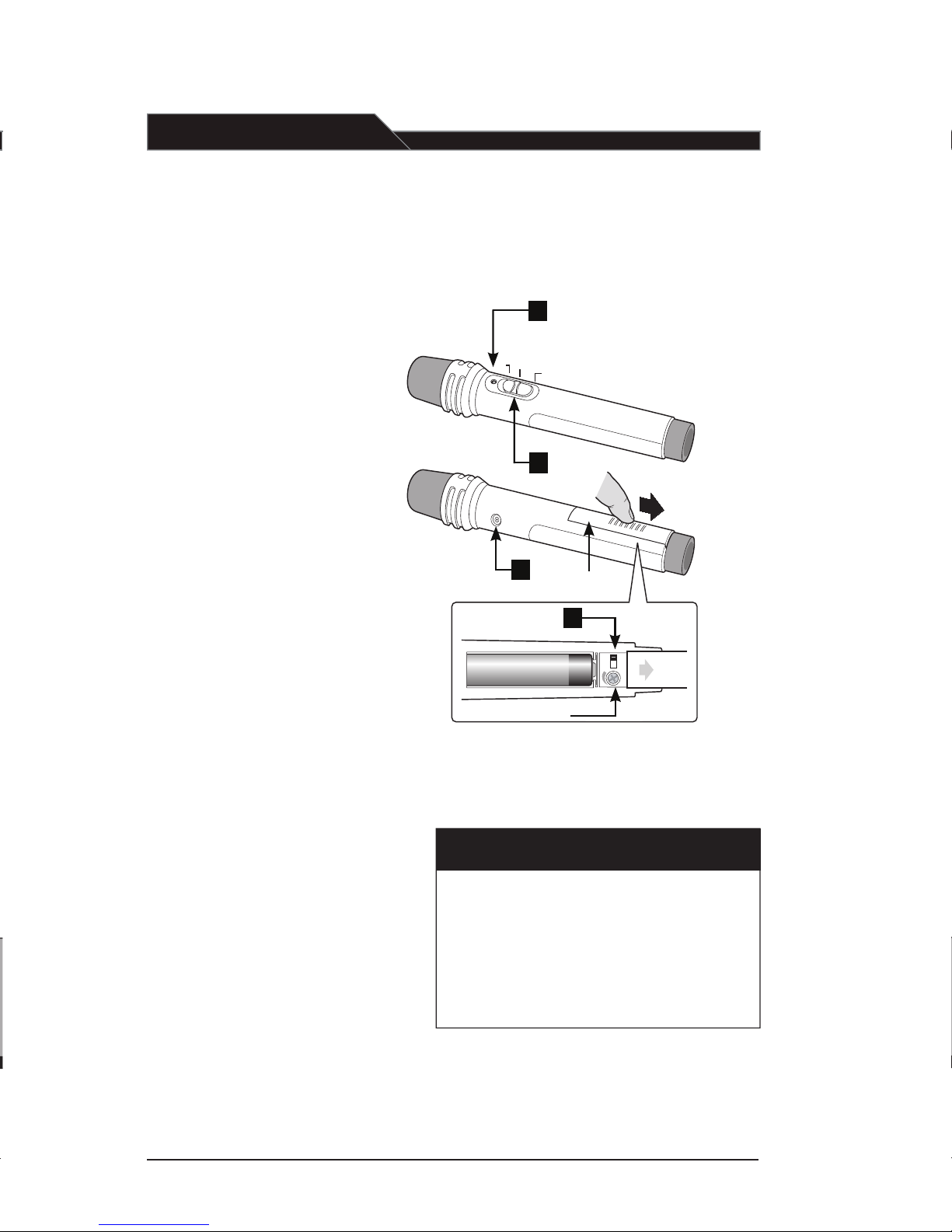
1. Power Switch: This 3-position
switch allows you to turn the
microphone on (up position),
mute the microphone
(middle position), and
turn off the microphone
(down position). The red LED
above the switch lights when the
switch is in the “mute” or power
“on” positions.
2. Channel Select Switch:
This switch allows you to
choose between Channel
A or Channel B. This switch
is set to Channel B at the factory.
3. Power/Charge LED Indicator:
This two-color LED indicator
is located directly above the
power switch. It glows red
when the HM-70 is
powered on and glows
green when charging.
4. Charger: Use this jack to
connect the charging cable
from the 780iR to the HM-70 for
daily battery recharging.
Optional HM-70 Handheld
Microphone/Transmitter:
Overview
The HM-70 handheld microphone is
an optional component that can be
ordered with the LES 750iR system.
This microphone is typically passed
around among students, so that
when they are asking a question or
reading aloud, all the other children
can clearly hear every spoken word.
[ caution! ]
Do not attempt to charge alkaline
batteries—they can overheat and
expand, creating a significant
hazard and damaging the LightMic.
(This is not covered by the warranty.)
Power/Charge LED Indicator
Power Switch
Charging Jack
Battery
Compartment
Channel Select Switch
Gain Adjust
3
1
4
2
top view of battery compartment
slide to open
on
mute
off
[12]
Page 15
POWER
IR AF
A
VOLUME
B VOLUME
AUX 1 VOLUME
AUX 2 VOLUME
IR AF
Step 4:
SPEAKER OUTPUT
OFF
ON
OFF
ON
OFF
ON
OFF
ON
1
2
EQUALIZE
R
6K
3
4K
+10
0
-1
0
DC POWER CHARGE
MIXED
AUDIO
OUT
OU
T
ADJ
ADJ
AUX
AUX
IN
1
IN
2
3
4
25
0
40
0
60
0
1K
1K6 2K5
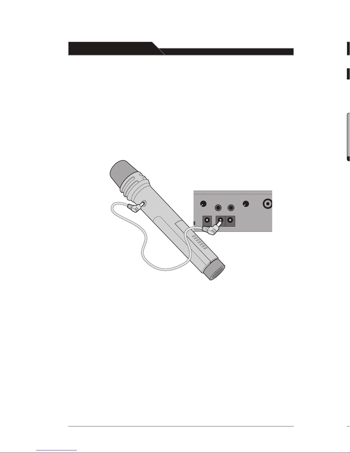
1. Ensure the HM-70 Handheld Microphone is turned OFF
(ON/OFF switch on the side of the unit). The LES 750iR can
be left on, but must be connected to AC power in order
to charge the microphone.
2. The HM-70s rechargeable batteries are
factory installed. Plug the smaller end of
the charging cable firmly into the jack
labeled CHARGER on the side of the
HM-70. Connect the larger end of the
charging to one of the CHARGE jacks
on the back of the LES 750iR.
Volume is set by adjusting the
volume control on the LES 750iR.
3. The power indicator light next to the
power switch glows green when the
cable is connected and charging
correctly. The light goes out when
fully charged.
Charging the HM-70:
[13]
Page 16
POWER
IR AF
A
VOLUME
B VOLUME
AUX 1 VOLUME
AUX 2 VOLUME
IR AF
6
The Channel A/B switch is located inside the
battery compartment. The switch is set to
Channel B at the factory.
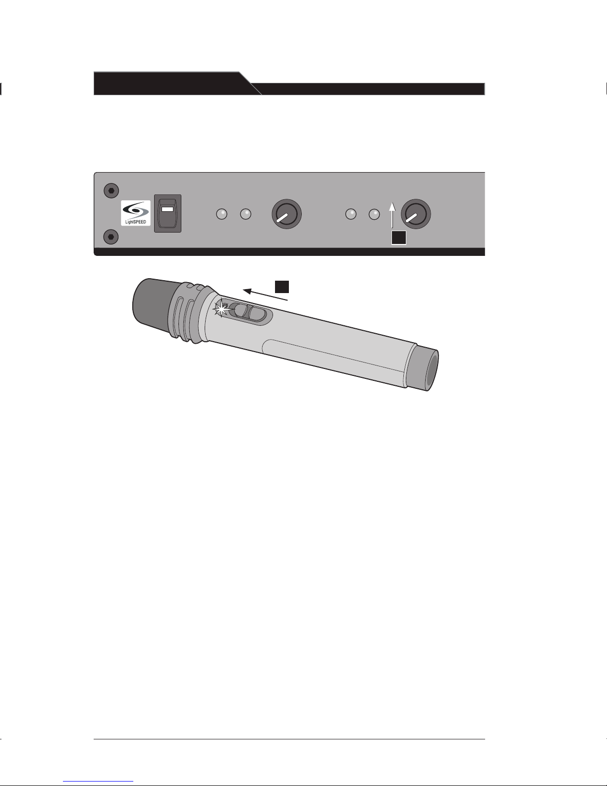
1. Slide the power switch on the side of
the HM-70 all the way up. The power
indicator LED will glow red and stay on.
2. The center position of the power
switch is MUTE. When in this mode,
the HM-70 is transmitting a signal, but
no audio can be heard through the sys tem. This is useful if you wish to
temporarily turn audio off during a
private conversation.
3. Do not adjust the audio gain adjuster
that is located in the battery
compartment. It has been preset by
factory technicians and is not intended
as a volume control.
4. When holding the HM-70, grip the
barrel in the center section just below
the power switch. Avoid gripping the
HM-70 around the bottom, cover ing the infrared emitters circling
the base. This could interrupt signal
transmission from the microphone to
the receiver.
5. Speak directly into the top of the
microphone at a normal level, holding
the grill about 2 inches from your
mouth, no lower than chin height.
6. Slowly adjust the B VOLUME control
to a desired level.
7. To turn the HM-70 off, slide the switch
to the OFF position (make sure the
power indicator light is off).
8. At the end of the day, make sure to plug
the microphone back into the charger
so it is ready for use the following day.
Operating the HM-70
ON
1
[14]
Page 17
AUX 1 VOLUME
AUX 2 VOLUME
LES - 7 50IR
AUX 1 VOLUME
AUX 2 VOLUME
LES - 7 50IR
MIXED
AUDIO
OUT
OU
T
ADJ
AUX
AUX
IN
1
IN
2
EQUALIZE
R
SENSOR
SHOR
T
SENSOR INPUTS
25
0
40
0
60
0
1K
1K6 2
K5
6K
3
4K
+10
0
-1
0
Green
LED
1. Ensure the LightMic is turned OFF.
The LES 750iR must be connected
to AC power in order to charge
the LightMic.
2. The LightMic’s rechargeable batteries
are factory installed. Plug one end of
the charging cable firmly into the
jack labeled CHARGER on the side of
the LightMic. Connect the other end
of the charging cable to one of the
MIC CHARGE jacks on the back of
the LES 750iR.
3. The triangle-shaped light on the
front of the LightMic transmitter
glows green when the cable is
connected and charging correctly.
The light goes out when fully charged.
4. The batteries will fully charge
in 8 to 12 hours.
5. It is best to leave the LightMic
charging until used, since the
batteries slowly lose their charge
when not in use.
The rechargeable NiMH
batteries must be fully
charged before regular
classroom operations.
Step 2 :
SPEAKER OUTPUT
DC POWER C
HARGE
MIXED
AUDIO
OU
T
OU
T
ADJ
ADJ
AUX
AUX
IN
1
IN
2
OFF
ON
OFF
ON
OFF
ON
OFF
ON
1
2 3
4
EQUALIZER
SENSOR
SHOR
T
SENSOR INPUTS
25
0
40
0
60
0
1K
1K6 2
K5
6K
3
4K
+10
0
-1
0
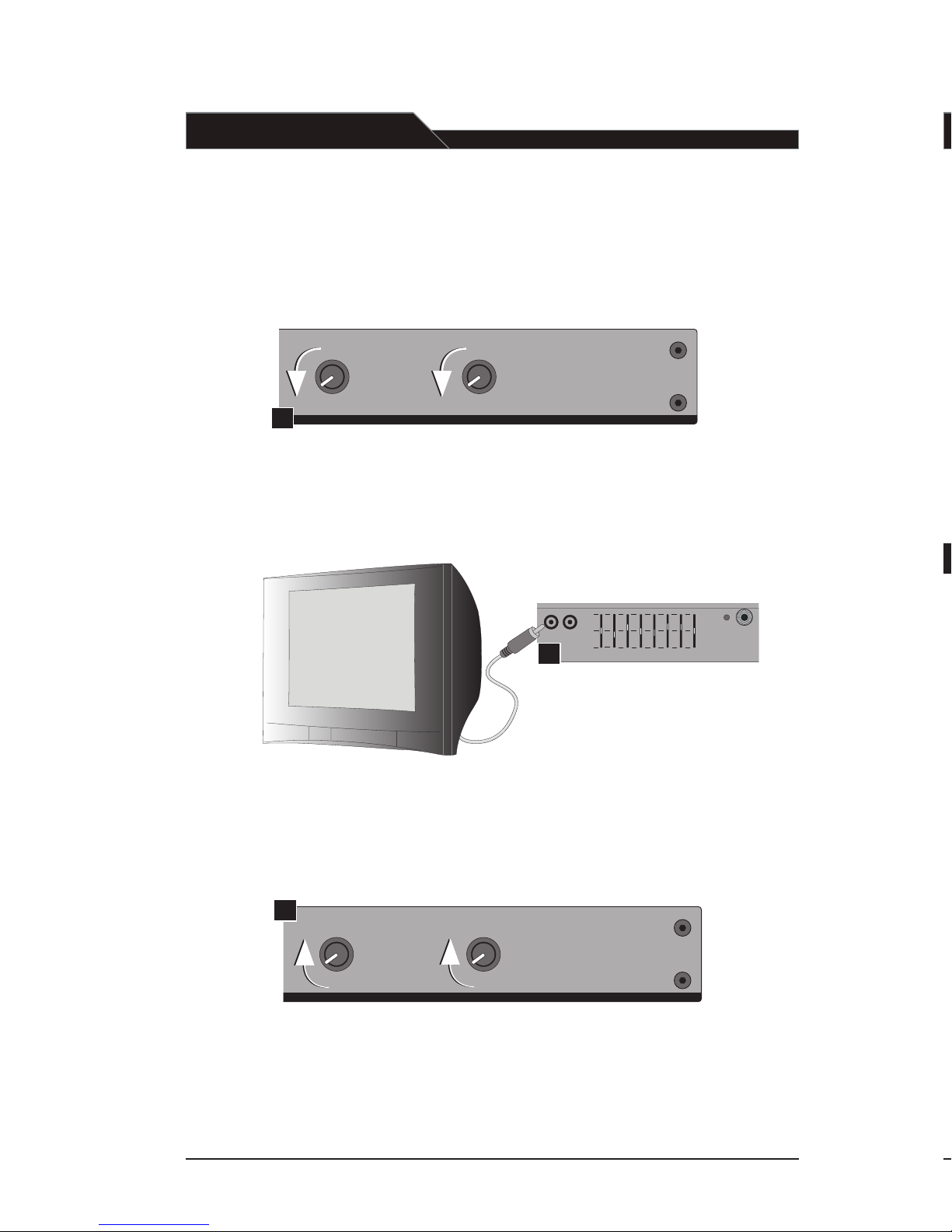
Input from External
Audio Equipment
Below are instructions on how to connect
an external audio device like a TV/VCR,
CD/DVD, cassette player, or projector.
1
1. Make sure to turn the AUX
(1 and 2) VOLUME controls on
the front panel all the way down
(fully counterclockwise).
2. Connect an RCA cable from the
audio source to one of the AUX
IN (1 or 2) jacks on the back of
the LES 750iR using an RCA-type
male connector. If the audio
source produces a stereo signal,
a stereo to mono adapter is
required (Part # AC-STM-ADPT).
3
2
3. With the LES 750iR power on,
adjust the corresponding AUX
(1 or 2) VOLUME knob on the front
to a desired level.
[15]
Page 18
AUX 1 VOLUME
AUX 2 VOLUME
LES - 750I R
[16]
SPEAKER OUTPUT
DC POWER CHARGE
MIXED
AUDIO
OUT
OUT
ADJ
ADJ
AUX
AUX
IN
1
IN
2
OFF
ON
OFF
ON
OFF
ON
OFF
ON
1
2 3
4
EQUALIZE
R
SENSOR
SHOR
T
SENSOR INPUTS
25
0
40
0
60
0
1K
1K6 2
K5
6K
3
4K
+10
0
-1
0
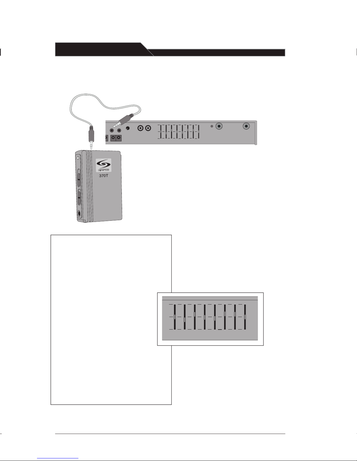
Output to Personal FM Transmitter
1. Make sure to turn the ADJ volume
controls on the back panel all the way
down (fully counterclockwise).
2. Using a cable with a 3.5mm connector
on one end, connect one of the MIXED
AUDIO OUT jacks to the input jack of
an FM transmitter, recorder, or other
device. It is important to determine the
size and type of audio input jack on the
device as many manufacturer’s products
differ. The LightSPEED LES-370
Personal FM System requires the
CA-MMC3535 cable.
3. With the LES 750iR turned on, turn
the corresponding ADJ volume control
to a desired level. When used with a
personal FM transmitter, typically this
volume control should be left at a
low level.
Audio Equalizer
The LES 750iR has a built-in 8-band
equalizer. This equalizer consists of eight
sliding controls that adjust the levels of
various high and low frequency sounds.
Because all loudspeakers and classrooms have different acoustical
properties, it can be difficult to
produce optimum sound
quality in every room. However,
this equalizer allows the installer to
fine tune the system, creating high
quality sound in every classroom
with any loudspeaker.
• The 8-band Equalizer is shipped from
the factory at preset levels based on
the speaker type. Refer to your speaker
install guide for more information on
these standard settings.
EQUALIZE
R
SENSOR
SHOR
T
SENSOR INPUTS
25
0
40
0
60
0
1K
1K6 2
K5
6K3
4K
+10
0
-1
0
Page 19
AUX 1 VOLUME
AUX 2 VOLUME
LES - 750IR
POWER
IR AF
A
VOLUME
B VOLUME
AUX 1 VOLUME
AUX 2 VOLUME
LES - 750IR
IR AF
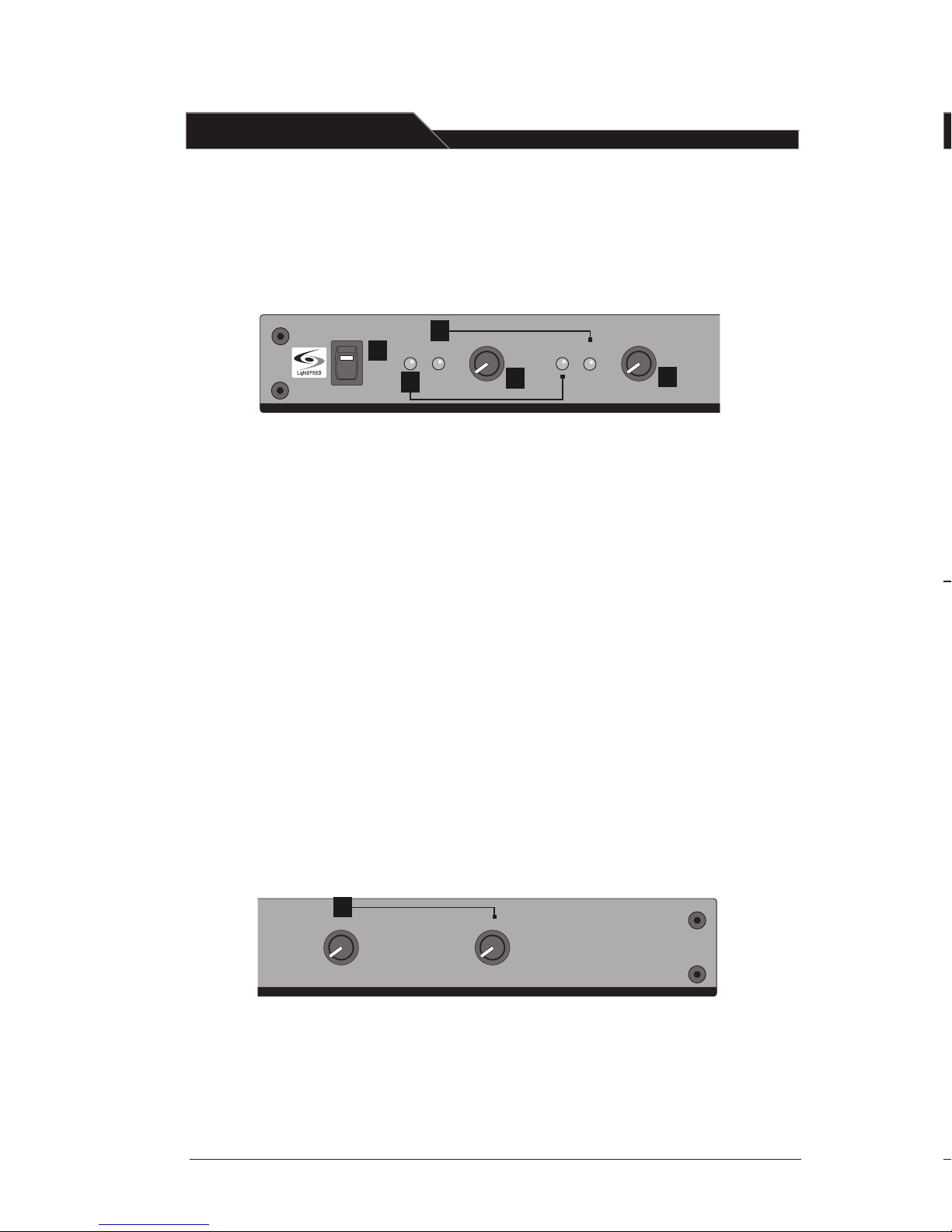
Front Panel Controls
1. POWER Switch/POWER Indicator:
This switch is used to turn the LES
750iR ON (switch up), or OFF (switch
down). When the POWER switch is
in the ON position, the red POWER
light will glow.
2. IR Indicators (IR): These lights will
glow red when the corresponding
microphone is turned on. This light
confirms the LES 750iR is receiving
the infrared signal.
3. AF Indicators (AF): These lights flash
green when audio (voice) from the
microphone is detected.
4. A VOLUME: Controls the volume
level of the microphone/trans mitter that is switched to Channel
A. Rotating the knob clockwise
increases output level.
5. B VOLUME: Controls the volume level
of the microphone/transmitter that
is switched to Channel B. Rotating the
knob clockwise increases output level.
6. AUX VOLUME: These knobs (AUX 1
and AUX 2) control the volume of
audio sources that are connected to
the AUX IN jacks located in the back
of the unit.
1
2
3
4
5
1. ON/OFF Switch: This switch,
located on the side of the LightMic,
turns the unit on or off. The red
triangle-shaped LED on the front
of the LightMic will light when
power is on.
2. Channel Select Switch (CH A/B):
This switch allows for selection
between Channel A or B. If you
are using a single microphone/
transmitter for your system, we
recommend using Channel A.
LT-70 LightMi
Controls and Connections
6
Clip
ON/OFF
Sw
itch
Channel
Select [A
-B]
Microphone
Power
LED
Charger
Co
nnector
External
Micr
ophone
Co
nnector
[17]
Page 20
R
SENSOR
SHOR
T
SENSOR INPUTS
1K6 2
K5
6K3
4K
+10
0
-1
0
9
10
AUX
AUX
IN
1
IN
2
EQUALIZE
R
SENSOR
SHOR
T
SENSOR INPUTS
25
0
40
0
60
0
1K
1K6 2
K5
6K3
4K
+10
0
-1
0
8
DC POWER CHARGE
MIXED
AUDIO
OU
T
OU
T
ADJ
ADJ
AUX
AUX
IN
1
IN
2
ON
EQUALIZE
R
SENSOR
SHOR
T
SENSOR INPUTS
25
0
40
0
60
0
1K
1K6 2
K5
6K
3
4K
+10
0
-1
0
3
4
5
6
7
SPEAKER OUTPUT
DC POWER CHARGE
MIXED
AUDIO
OU
T
OU
T
ADJ
ADJ
AUX
AUX
IN
1
IN
2
OFF
ON
OFF
ON
OFF
ON
OFF
ON
1
2 3
4
EQUALIZE
R
SENSOR
SHOR
T
SENSOR INPUTS
25
0
40
0
60
0
1K
1K6 2
K5
6K
3
4K
+10
0
-1
0
1
2
[18]
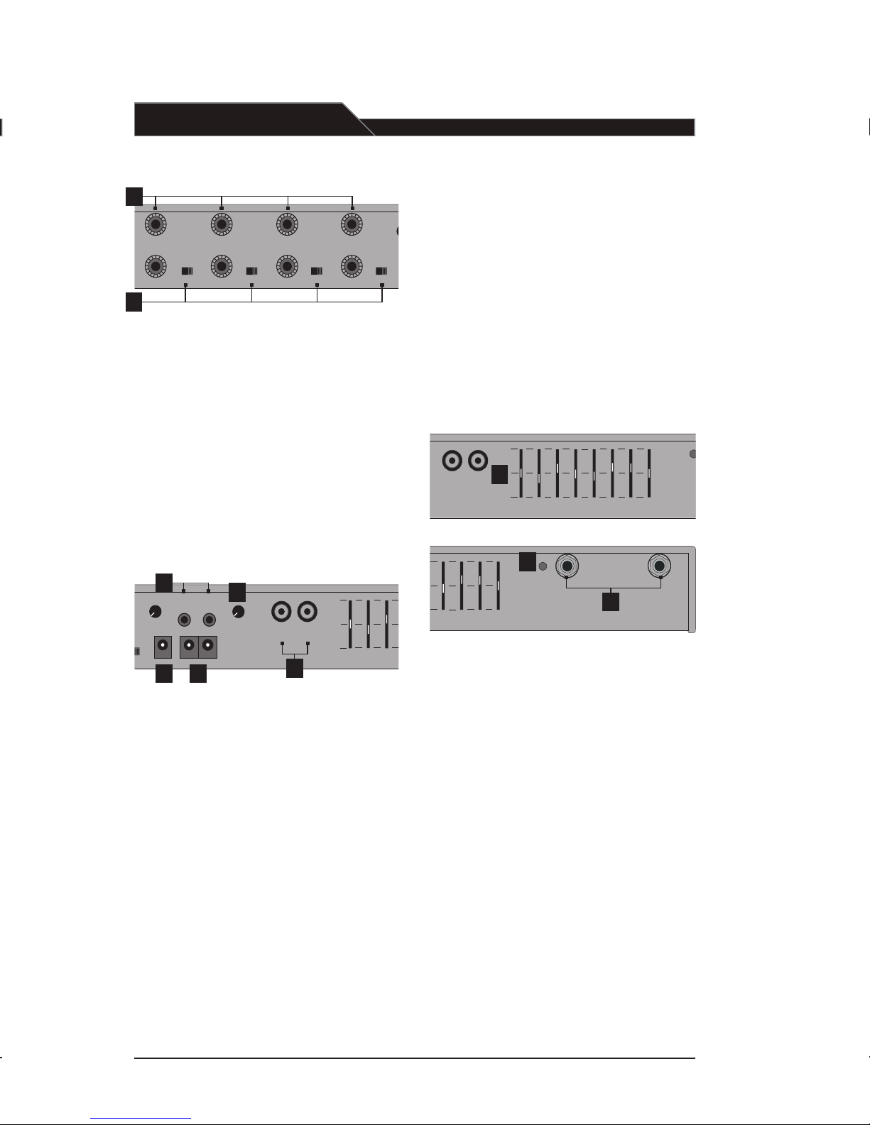
1. SPEAKER OUTPUTS (1-4): These
binding post connectors are used to
connect the 750iR to the loudspeakers.
2. SPEAKER ON/OFF: These individual
speaker switches can be used
to turn off the audio in a specific area
of the classroom where there may be
a learning group or quiet time.
3. DC POWER: Plug the AC/DC power
supply into this jack.
4. CHARGE: These jacks charge the
LightMic(s) and optional handheld
microphone with the supplied
charging cable(s).
5. MIXED AUDIO OUT: These output
jacks send the processed audio signal
the external equipment such as a
recorder or an assistive listening
device like LightSPEED’s LES-370
Personal FM System.
6. ADJ: These controls adjust the
output level of the audio being
sent out of the unit via the MIXED
AUDIO OUT jacks.
7. AUXILIARY INPUTS (AUX IN 1 & 2):
These RCA jacks receive audio
from external sources such as a
TV, VCR, CD, DVD, cassette,
computer, LCD projector, etc.
8. 8-Band EQUALIZER: The sliding controls
adjust the levels of the various audio
frequencies. This allows the installer to
properly equalize the system to produce
optimum sound quality in every room
with any speaker.
9. SENSOR INPUTS: The cable from the
IR sensor connects to either of these two
inputs. Up to two IR sensors can be
connected to the LES 750iR to cover
larger or odd shaped classrooms.
0. SENSOR SHORT: If there is a short in
one of the sensor cables, this LED glows
as a warning signal.
1
Rear Panel Controls
Page 21

5. IR Sensor Placement
Sensor location is very important for
optimum performance of the LES 750iR
Classroom Amplification System.
• BEST: On the ceiling at or near the
middle of the classroom.
• GOOD: High and centered on the
long wall.
• AVOID: Locations in corners, on walls
at heights lower than 7 feet, or in
places where the line of site is or
could be obstructed.
• Other Considerations: Notice if there
are large areas of dark color (ie. black
boards or dark colored walls). Since
these dark color reflects less light, it
may be necessary to locate the sensor
near these areas.
a. Suspended Ceiling Mount
• Lift the ceiling tile nearest the grid rail in
your desired sensor location. Guide one
side of the C-clip over one edge of the
grid rail. Providing firm support to the
back of the grid rail with one hand (to
prevent bending), firmly and carefully
snap the second side of the C-clip over
the edge of the rail.
• Uncoil sensor wire. Connect one end of
the sensor cable to the plug on the
sensor. Loosely secure wire overhead
and route it back to the receiver.
Five-Year Limited Warranty
to Original Purchaser
The LightSPEED LES 750iR Infrared Class
room Amplification System is warranteed
against malfunction due to defects in
materials and workmanship for a period
of five years beginning at the date of the
purchase. Batteries and the optional TK250 Headset Microphone are warranteed
for one year. Products will be repaired or
replaced at LightSPEED’s option during the
warranty period.
Warranty does not extend to finish, appear
ance, or malfunctions due to abuse or
misuse. Repairs performed by anyone
other than LightSPEED will void this
warranty. Our Service Department
(800.732.8999, 7 a.m. – 5 p.m., PST) will
handle all your repair/replacement needs.
If you review these instructions and still
have questions, write down the serial
number and model number of your system
and call LightSPEED Technical Services at
800.732.8999, 7 a.m. - 5 p.m. PST.
Tips on Using Classroom
Amplification
These helpful suggestions are provided
to maximize the successful use of your
new LES 750iR Infrared Classroom
Amplification System.
• Speak in a natural voice. A normal
conversational speech level will provide
an adequate signal. It is not necessary to
increase the intensity of your voice—the
amplification system provides adequate
amplification (approximately 5–10 dB)
above ambient room noises.
• Avoid wearing jewelry that may rub or
bump against the microphone.
• Turn the LightMic off during private
conversations with a student, parent, or
other classroom visitor. You can also
cover the LED lens on top of the
LightMic to block the signal.
• Recharge batteries each night. When
recharged nightly, operating time
(actual usage) for the transmitters will
last through a typical school day. Your
rechargeable batteries will last for a
normal school year when cared
for properly.
[ caution! ]
Do not attempt to charge alkaline
batteries—they can overheat and
expand, creating a significant
hazard and damaging the LightMic.
(This is not covered by the warranty.)
[19]
Page 22

Troubleshooting Guide
Please go through this checklist before
calling LightSPEED Service Department.
Battery Check:
• Confirm batteries are charged
each night. With proper charg ing, batteries will last about
one school year.
• Transmitters are charged via a
jumper cable from the back of the
LES 750iR. Make sure plugs are
secured and in the proper jacks.
• Confirm the green charging light
located on the front of the LightMic
is on while charging.
• Ensure the LightMic is turned off
while charging.
Hearing Static or Buzzing:
• If using two LightMics, check that
they are not set to the same
channel. If so, select a different
channel for one of the LightMics.
• Keep the LES 750iR at least 6 feet
away from computers.
Low Volume:
• Check volume level on the LES
750iR and adjust as necessary.
• Make sure the LightMic is positioned
properly around the neck (the top of
it should sit just below the collar-
bone). If the microphone is too far
away from the speaker’s mouth, it will
not properly pick up the voice.
Sound Fades In and Out (Drop Out):
• Test LightMic with fully charged
batteries. LED light on front of mic
will glow bright red.
• Make sure there is nothing obstruct ing the lens on the LightMic. The
LightMic needs to be worn around
the neck with the lens pointing out
or held in the hand without covering
the lens for proper transmission.
• Make sure there is nothing obstruct ing the Infrared sensor. The sensor
should be installed on the ceiling or
high on a wall for proper reception.
No Sound From Speaker:
• Confirm the LightMic and the LES
750iR are turned on and have
matching channels. Check both A
VOLUME and B VOLUME to
ensure they are set correctly.
• Confirm amplifier power
supply is the correct type – if in
doubt, call LightSPEED. In addition,
confirm that the power supply is
connected securely in the wall outlet
and into the DC POWER connector
on the back of the 750iR.
• Turn the 750iR on. Confirm that
the POWER light located on the
front panel switch is on.
• Turn the LightMic on and confirm
that the corresponding red IR light,
located on the front panel of the
750iR, is glowing. When speaking
into the LightMic, the green AF
light will flash/flutter with your
voice volume.
• Confirm that the batteries in the
transmitter are fully charged. When
they are, the red indicator will
glow steadily.
• Confirm that the speaker wires are
connected correctly to the back of
the LES 750iR (refer to speaker install
guide) and make sure that the
speaker switch for that output jack is
in the ON position.
[20]
Page 23

POWER
IR AF
A
VOLUME
B VOLUME
AUX 1 VOLUME
AUX 2 VOLUME
LES - 750I R
IR AF
LES 750iR Classroom Amplification System Components:
SR-70 Infrared Sensor Cable
SR-70 Infrared Sensor
LES 750iR Receiver/Amplifier
LT-70 LightMic
Microphone/
Transmitter
LES 750C: Infrared receiver/amplifier/mixer with built-in
charger
LESLT-70-TCC7: “LightMic” rechargeable microphone/transmitter
with lavaliere cord, batteries and charging cable
LESHM-70: Handheld microphone/transmitter with batteries
and charging cable
BA-NH1: Rechargeable AA battery (Nickel Metal Hydride)
AC-TCC7: Charging cable for LT-70 and HM-70 microphones
AC-LTCB: Lavaliere cord for LT-70
PS-24V-2.5: Power supply/battery charger for 750iR
LESSR70F: Infrared sensor with wall or ceiling mounting bracket
MC-TK250LTM: Optional noise-canceling headset microphone
to be used with LT-70
CA-RCA6: 6’ dual RCA audio cable
CA-RCA24: 24’ dual RCA audio cable
CA-MMC3535: 3.5 mm mono to 3.5 mm mono audio cable
CA-MMC2535: Audio patch cable (2.5 mm mono to 3.5 mm mono)
SPEAKERS: Contact LightSPEED at 800.732.8999 for
loudspeaker information
Individual Components and Optional Accessories
[21]
Page 24

Overall System Specifications:
Carrier Frequencies (IR) 2.06/2.54 MHz
Frequency Stability +
/– 3%
Maximum Deviation
+/– 50 kHz
Dynamic Range > 73 dB
Signal-to-Noise Ratio
> 73 dB
Frequency Response 40 Hz - 20 kHz (– 3 dB)
Receiver Specifications:
Receiver Type Superheterodyne
Receiver Sensitivity 6
µV for 60 dB S/N ( > 25 dBuV)
Image and Spurious Rejection > 40 dB
Reception Selectivity 40 kHz
Squelching Threshold 3.2
µV
Amplifier Specifications:
Power Output (System Total) 12 W per channel (48 W total)
Total Harmonic Distortion < 1% @ 20 W
Speaker Load Impedance 4 Ohms
Power Supply (UL Listed) 24 V/2.5 A
Dimensions 18 x 9 x 3 (H x W x D inches)
Weight 7 lbs.
Inputs:
TV/VCR RCA – Line Level
IR Sensors (2) “F” Connector
Outputs:
Auxiliary Outputs (2) 3.5 mm
Speaker Outputs (4) Binding Post Connectors
Transmitter Specifications:
Audio Distortion < 1%
Spurious Emissions < 30 dB
Built-in Microphone Uni-directional Electret
Battery Power (1-year warranty) 2 AA NiMH Rechargeable
Dimensions 1.4 x 1 x 4.6 (W x D x H inches)
Weight 3.04 oz (w/batteries)
External Sensor:
Power By Receiver Unit
Reception Coverage 360
º, Ceiling-mount
Cable 50 ft., Plenum-rated Co-ax
Mounting Ceiling clip/Wall bracket
Diodes 32
[22]
Page 25
Table of Contents
LES 750iR Infrared Classroom Amplification System:
Overview
LES 750iR System Components
System Installation:
1. Unpacking
2. Location
3. Speaker(s)
4. Receiver/Amplifier
5. IR Sensor Placement
a. Suspended Ceiling Mount
b. Wall or Solid Ceiling Mount
6. LightMic Microphone/Transmitter
7. Testing
LT-70 LightMic™ Microphone/Transmitter Controls and Connections
System Operation:
Step One: Powering the LES 750iR
Step Two: Charging the LightMic
Step Three: Operating the LightMic
Step Four: Adjusting the Volume
Step Five: Operating an Optional Second Microphone Simultaneously
Optional HM-70 Handheld Microphone Transmitter:
Overview
HM-70 Controls
Charging the HM-70
Operating the HM-70
Input from External Audio Equipment
Output to Personal FM Transmitter
Audio Equalizer
Front Panel Controls
Rear Panel Controls
Tips on Using Classroom Amplification
Five-year Limited Warranty to Original Purchaser
Troubleshooting Guide
Individual Components and Optional Accessories
Overall System Specifications
User Notes
[23]
User Notes
Record your system serial numbers and purchase information. This is helpful when ordering
additional components, accessories, and/or warranty service.
serial number
optional
component
serial number
LT-70 LightMic
standard
components
SR-70 IR Sensor
Power Supply
LES 750iR
Speakers
Wall-Mounting Shelf
HM-70 Handheld
Microphone
TK-250 Headset
Microphone
Page 26

LightSPEED
LightSPEED
 Loading...