

Page 1
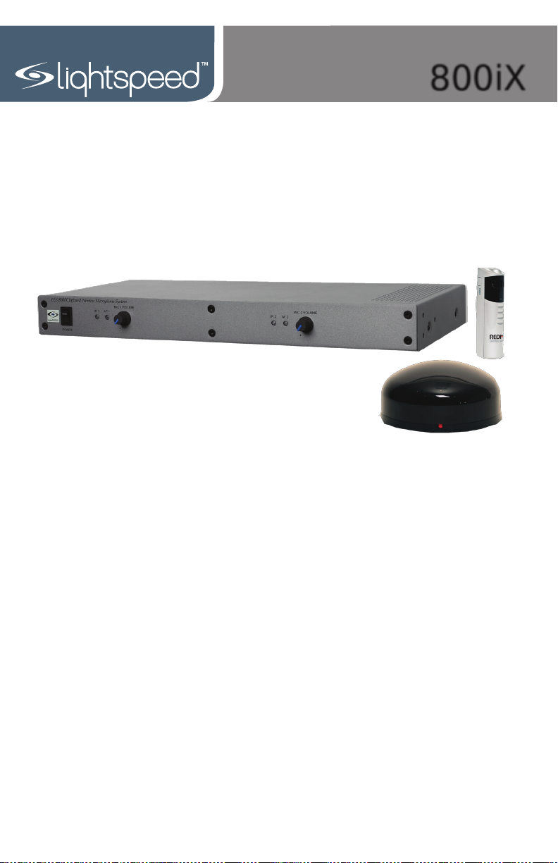
800iX
Classroom Audio System
User Manual
Page 2
800iX User Manual
800iX User Manual
CONGRATULATIONS!
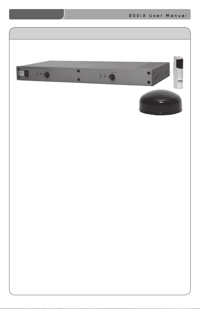
Congratulations on your purchase of the 800iX Infrared Wireless
Microphone System! This simple, yet powerful technology provides the
ability to add the benets of infrared microphone technology to existing
ampliers or to Lightspeed’s popular 880iR and 850iR systems to create
up to a four-channel solution for the classroom.
The 800iX is a two-channel receiver that allows the use of up to two
additional microphones simultaneously. A standard IR sensor can provide
high quality reception in rooms up to 1600 square feet. By connecting
additional infrared sensors to the receiver, the coverage area can be
expanded to provide optimal reception in varying room sizes
and congurations.
The REDMIKE is a two-channel, rechargeable classroom microphone that
is clipped to a lavaliere cord and worn around the neck for teacher use, or
it can be used as a standard handheld microphone for students to pass
around when speaking.
800iX User Manual | i
Page 3
800iX User Manual
800iX User Manual
SAFETY INSTRUCTIONS AND CERTIFICATIONS
CAUTION
RISK OF ELECTRIC SHOCK DO NOT OPEN
CAUTION: TO REDUCE THE RISK OF ELECTRIC SHOCK
DO NOT REMOVE COVER (OR BACK)
NO USER-SERVICEABLE PARTS INSIDE
REFER SERVICING TO QUALIFIED PERSONNEL
The lightning ash with arrowhead symbol
within an equilateral triangle is intended to
alert the user to the presence of uninsulated
“dangerous voltage” within the product’s
enclosure, that may be sufcient magnitude to
constitute a risk of electric shock.
The exclamation point within an equilateral
triangle is intended to alert the user to
the presence of important operating and
maintenance (servicing) instructions in the
literature accompanying the appliance.
CERTIFICATIONS
Complies with 72/23/EEC Low Voltage Directive
and 89/336/EEC Electromagnetic Compatibility
Directive. Compliance was demonstrated to the
following specications as listed in the Ofcial
Journal of the European Union:
EN 60950: Electrical Safety – A1:1993,
A2:1993, A3:1993, A4:1997
EN 55022: RF Emissions, Information
Technology Equipment
EN 55024: EMC Immunity Standard
EN 61000-3-2: Harmonics
EN 61000-3-3: Voltage Fluctuation
Lightspeed Technologies launched a formal
product recycle program in Europe that
complies with the European Union Directive
2002/96/EC on Waste Electrical and Electronic
Equipment (“WEEE Directive”). Please visit our
website at www.Lightspeed-tek.com for more
information.
This product is manufactured using lead-free
processes and is free of other materials
harmful to the environment. It conforms to the
most stringent new European guidelines for
consumer products (RoHS).
1. Read Instructions—All safety and
operation instructions should be read
before this Lightspeed product is
operated.
2. Retain Instructions—The safety and
operating instructions should be kept
for future reference.
3. Heed Warnings—All warnings on
this Lightspeed product and in these
instructions should be followed.
4. Follow Instructions—All operating
and other instructions should
be followed.
5. Water and Moisture—This
Lightspeed product should not be
used near water.
6. Heat—This Lightspeed product should
be situated away from heat sources
such as radiators, etc.
7. Power Sources—This Lightspeed
product should be connected
to a power supply only of the
type described in the operation
instructions or as marked on this
Lightspeed product.
8. Power Cord Protection—Power
supply cords should be routed so that
they are not likely to be walked upon
or pinched by items placed upon or
against them.
9. Object and Liquid Entry—Care should
be taken so that objects do not fall
onto and liquids are not spilled into
the Lightspeed product.
10. Damage Requiring Service—This
Lightspeed product should be serviced
only by qualied service personnel.
The user should not attempt to service
this Lightspeed product.
11. Prevent Electric Shock—Do not use
this polarized plug with an extension
cord, receptacle or other outlet unless
the blades can be fully inserted to
prevent blade exposure.
ii | 800iX User Manual
Page 4

800iX User Manual
800iX User Manual
TABLE OF CONTENTS
800iX CLASSROOM AUDIO SYSTEM
Safety Instructions and Certications ........................................................................ii
SECTION 1: System Overview ................................................................................. 1
System Components ............................................................................................. 2
Front Panel Controls ............................................................................................... 3
Rear Panel Controls ............................................................................................... 4
REDMIKE Controls and Connections ...................................................................... 5
Cradle Charger Controls and Connections ............................................................. 6
Optional LT-71 Controls and Connections .............................................................. 7
Optional HM-70 Controls and Connections ............................................................ 8
SECTION 2: Installation ........................................................................................... 9
Unpacking Your System .................................................................................................... 10
Location of the Receiver/Amplier..................................................................................11
IR Sensor Installation ............................................................................................12
Suspended Ceiling Mount .................................................................................................. 13
Wall/Solid Ceiling Mount .................................................................................................... 13
Audio Integration ...............................................................................................................14
Finalizing Connections ......................................................................................................15
Final Check ..........................................................................................................................16
SECTION 3: Initial Set-up, Charging and Optional Features ................................17
Initial Set-Up: REDMIKE ........................................................................................18
Initial Set-Up: Optional LT-71 ................................................................................19
Initial Set-Up: Optional HM-70 ..............................................................................20
Charging the REDMIKE .........................................................................................21
Charging the Optional LT-71 .................................................................................22
Charging the Optional HM-70 ...............................................................................23
Using the REDMIKE to Amplify External Audio Equipment ....................................24
SECTION 4: Troubleshooting, Daily Use and Warranty.........................................25
Troubleshooting Guide ..........................................................................................26
Daily Use Instructions ...........................................................................................27
Tips on Classroom Audio ......................................................................................28
Warranty Statement .............................................................................................28
System Specications ..........................................................................................29
Individual Components and Optional Accessories ................................................30
User Notes ............................................................................................................31
800iX User Manual | iii
Page 5

SECTION 1
System Overview
800iX User Manual
1 | 800iX User Manual
Page 6
800iX User Manual
LT- 71
SYSTEM COMPONENTS
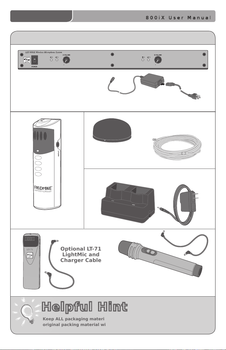
800iX Infrared Wireless Microphone Receiver and Power Supply
Sensor Cable
SR-70F Infrared
Sensor
Charging Cradle and Power Supply
REDMIKE Classroom
Microphone
Helpful Hint
Keep ALL packaging materials. If the system must be returned, using the
original packing material will be quick, convenient and prevent damage.
Optional LT-71
LightMic and
Charger Cable
Optional HM-70 Handheld
Microphone and Charger Cable
800iX User Manual | 2
Page 7
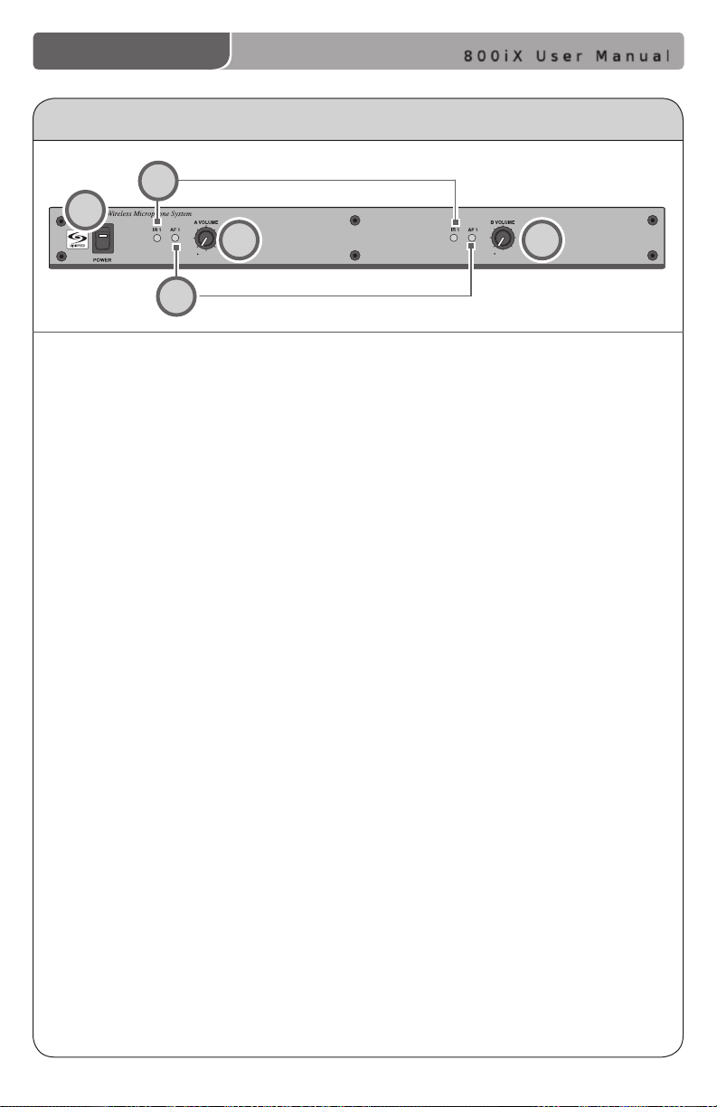
FRONT PANEL CONTROLS
2
2
1
4
3
800iX User Manual
5
1. POWER Switch/POWER Indicator:
This switch is used to turn the
800iX ON (switch up), or OFF
(switch down). When the POWER
switch is in the ON position, the
POWER light will glow red.
2. IR Indicators (IR): These
lights will glow red when the
corresponding microphone is
turned on. This light conrms
the 800iX is receiving a steady
infrared signal.
3. AF Indicators (AF): These lights
ash green when audio (voice)
from the microphone is detected.
4. A VOLUME: Controls the volume
level of the teacher microphone
that is switched to Channel A.
Rotating the knob clockwise
increases output level.
5. B VOLUME: Controls the volume
level of the optional second
microphone that is switched to
Channel B. Rotating the knob
clockwise increases output level.
3 | 800iX User Manual
Page 8
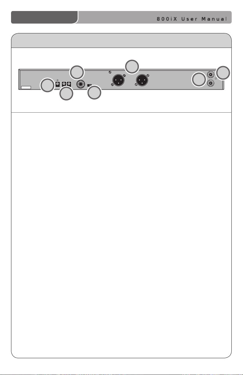
REAR PANEL CONTROLS
2.06/2.54
AUDIO OUTPUT
DC POWER
16V/1A
CHARGE
LEVEL
MIC
LINE
CHANNEL A
CHANNEL B
SENSOR INPUTS
SHORT
BALANCED
AUDIO
OUTPUTS
+
—
800iX User Manual
3
1
2
1. DC POWER: Plug the 24 V power
supply into this jack.
2. CHARGERS: These jacks can be used
to charge the optional LightMic or
handheld mic as an alternative to
connecting them to the REDMIKE
cradle charger.
3. AUDIO OUTPUT: This 1/4” unbalanced
audio output jack may be connected
to a “line in” jack on a mixer/amplier.
This output is a mixed audio of
channels A and B.
4. LEVEL (MIC/LINE): Changes the audio
level output from the audio
output jack to “mic” or “line” level.
4
5
7
6
5. BALANCED AUDIO OUTPUTS: Two
independent audio outputs that may
be connected to a balanced
microphone input jack on the mixer/
amplier using a standard XLR
microphone cable.
6. SENSOR INPUT: The IR sensor cable
connects to the sensor input.
Connect additional sensors to the
800iX to cover large or odd-shaped
classrooms.
7. SENSOR SHORT: This LED glows
when there is a short in one of the
sensor cables.
800iX User Manual | 4
Page 9
800iX User Manual
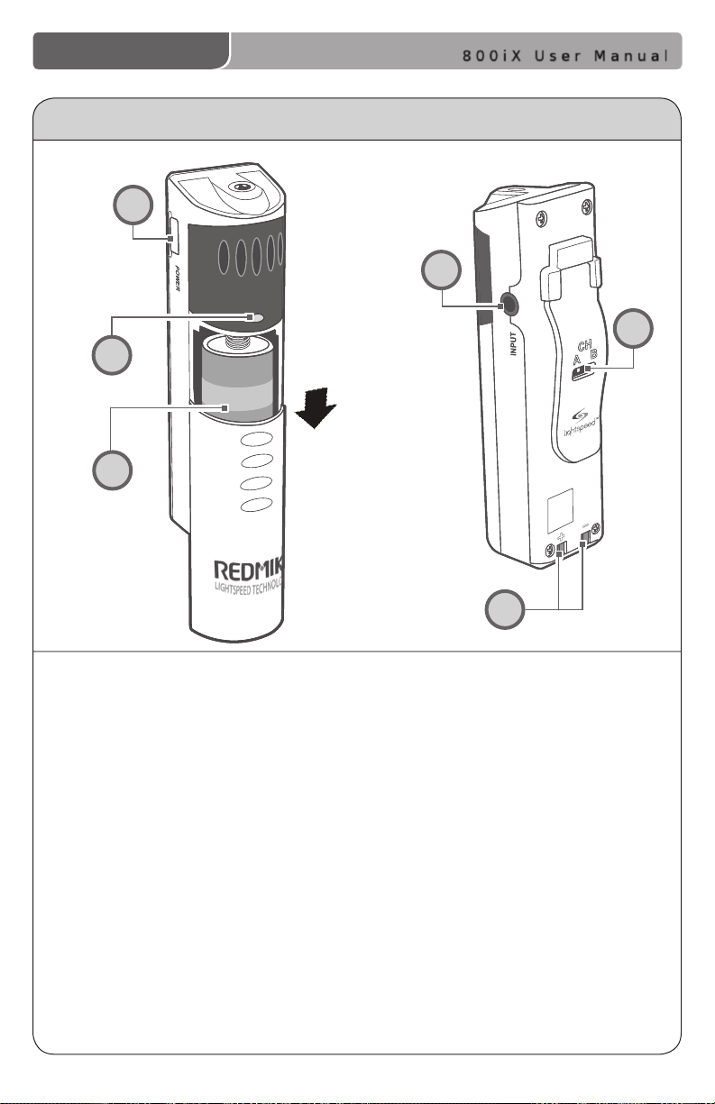
REDMIKE CONTROLS AND CONNECTIONS
1
4
2
3
5
1. POWER BUTTON: Press this button
to turn the REDMIKE ON, press
again to turn it OFF (mute).
2. POWER/LOW BATTERY INDICATOR:
A BLUE light indicates the REDMIKE
is on and fully charged. A RED light
indicates a charge is needed.
3. BATTERY COMPARTMENT: To
access the battery compartment,
slide the door downward.
The battery should only be
replaced by a Lightspeed AA
rechargeable sensing battery
(part # BA-NH2A27).
5 | 800iX User Manual
6
4. AUDIO/MICROPHONE INPUT: Use this
input to plug in a laptop, MP3 player
or other audio source to wirelessly
transmit audio to be played through
the system. Alternatively, an external
microphone can be connected.
5. CHANNEL SELECT SWITCH (CH A/B):
This switch allows for selection between
Channel A or B. If you are using a single
microphone, we recommend using
Channel A.
6. CHARGER CONTACTS (+ -): These
contacts interface with the charging
tabs in the BC-RMCC cradle charger
for daily charging. Simply place the
REDMIKE in the charger.
Page 10

800iX User Manual
CRADLE CHARGER CONTROLS AND CONNECTIONS
1
2
1. CHARGE INDICATORS: The light
glows RED while the REDMIKE is
charging. When fully charged, the
light will glow GREEN.
2. DC POWER PORT: Connect the DC
power cord here.
3
3. OPTIONAL CHARGING PORT: Plug the
charging cord for the optional LT-71 or
the HM-70 microphones here.
800iX User Manual | 6
Page 11
800iX User Manual
LT- 71
LT- 71
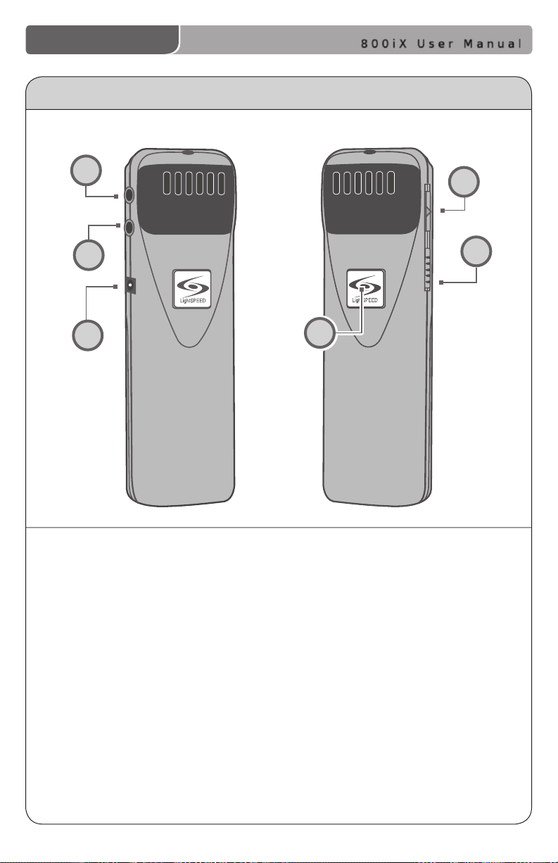
OPTIONAL LT-71 CONTROLS AND CONNECTIONS
4
5
6
1. ON/OFF/MUTE Switch: This switch
turns LT-71 ON or OFF (mute).
2. Channel Select Switch (CH A/B):
This switch allows for selection
of Channel A or B. If you are
using a single microphone, we
recommend using Channel A.
3. Power/Charge Indicator: The
light glows BLUE when the LT-71
is powered ON, RED when being
charged.
4. External Microphone Input (MIC):
Use the 3.5mm MIC jack for the
optional TK-250 headset microphone
(part# MC-TK250LTM).
1
2
3
5. Auxiliary (AUX): Plug a laptop, MP3
player or other audio source into
this jack to wirelessly transmit the
audio signal to be played through
the system.
6. Charger Input (CHARGER): Plug
the charging cable from the
charger into this jack for daily
charging. The LED on the front will
glow RED to indicate charging.
7 | 800iX User Manual
Page 12
800iX User Manual
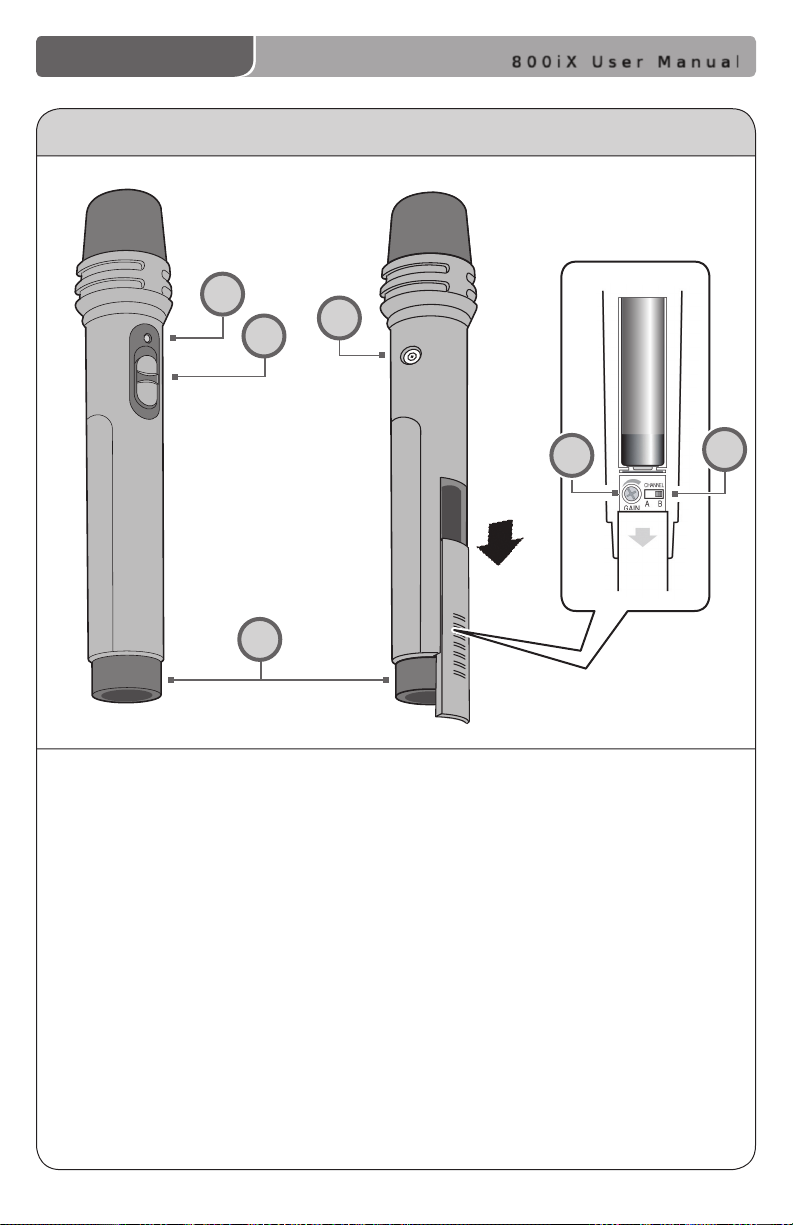
OPTIONAL HM-70 CONTROLS AND CONNECTIONS
3
4
1
NiMH
6
2
5
1. ON/OFF/MUTE Switch: This switch
turns the unit ON, OFF or MUTE.
2. Channel Select Switch (CH A/B):
Located in the battery compartment,
the switch is set to Channel B at
the factory.
3. Power/Charge Indicator: The
light glows RED when the HM-70
is powered ON, GREEN when
charging.
4. Charger Input (CHARGER): Plug
the charging cable from the charger
into this jack for daily charging.
5. Infrared Emitters: Avoid covering
the emitters as you grip the HM-70
as this could interrupt signal
transmission from the microphone.
6. Volume Gain Adjustment:
Optimum volume level is
pre-set at the factory and no
adjustment should be necessary.
800iX User Manual | 8
Page 13

SECTION 2
Installation
800iX User Manual
9 | 800iX User Manual
Page 14
800iX User Manual
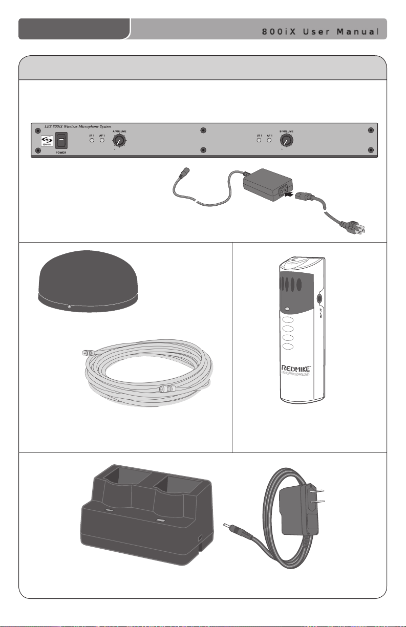
1. UNPACKING YOUR SYSTEM
Ensure that you have received all of the components of your system.
800iX Infrared Receiver/Amplier and Power Supply
SR-70F Infrared Sensor and cable
Charging Cradle and Power Supply
REDMIKE™Classroom
Microphone
800iX User Manual | 10
Page 15
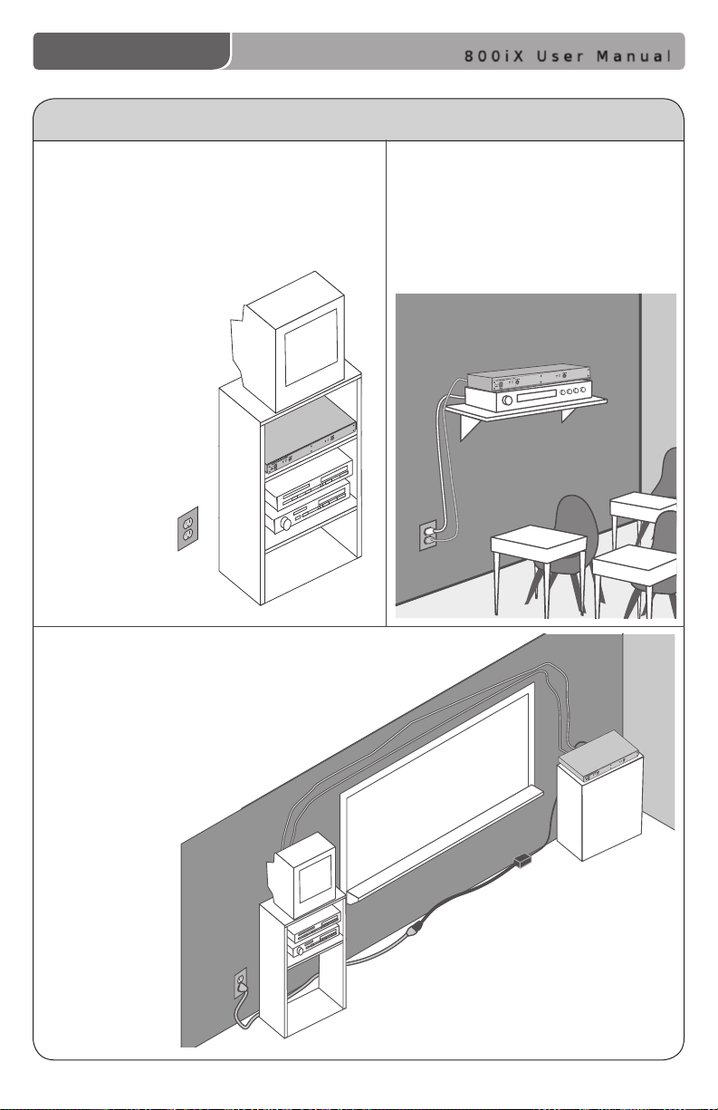
2. LOCATION OF THE RECEIVER
800iX User Manual
• Before running wires to the 800iX
or plugging in, nd a suitable,
stable location for the amplier.
Ideally, the teacher should have
ready access and an electrical
outlet should be within
six feet. The best
possible location
for the 800iX is in a
media cabinet with
any existing audio/
video equipment.
• Wires should be routed back directly to the
amplier, so select a location that is free from
obstructions that may make routing wire
difcult.
(Example: placing the 800iX near
a whiteboard or bulletin board
would require the wiring
to be run an extra
distance in
order to reach
the amplier.)
Best
• A good location would be on any
stable bookcase or shelf within
6 feet of an electrical outlet. The
optional Lightspeed wall shelf (part
#AC-800WB) is specically designed
to support the 800iX.
Good
11 | 800iX User Manual
Avoid!
Page 16
800iX User Manual
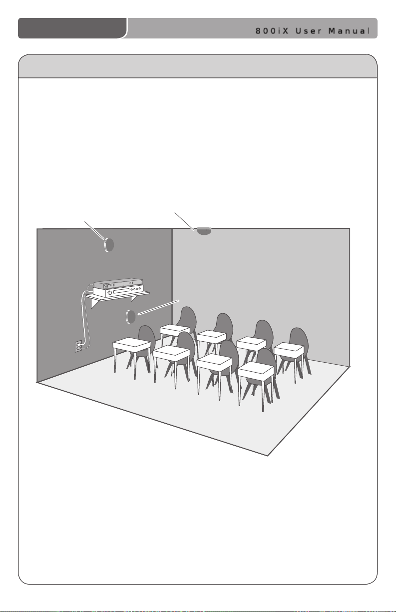
3. IR SENSOR INSTALLATION
Sensor location is very important for optimum performance of the 800iX Classroom
Audio System.
• BEST: On the ceiling at or near the middle of the classroom.
• GOOD: High and centered on the long wall.
• AVOID: Locations in corners, on walls at heights lower than 7 feet, or in places
where the line of sight is or could be obstructed.
Good placement
Best placement
Avoid!
800iX User Manual | 12
Page 17
800iX User Manual
IR SENSOR INSTALLATION (cont’d)
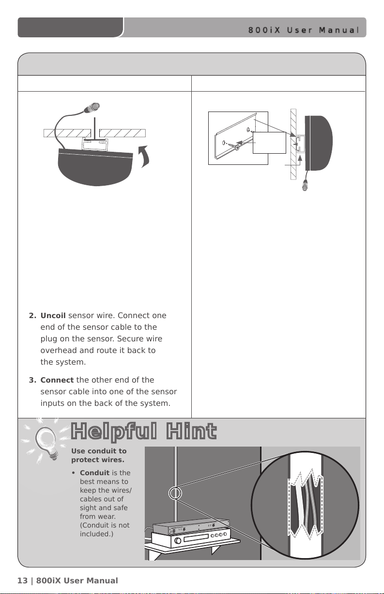
Suspended Ceiling Mount
1. Lift the ceiling tile nearest the grid
rail in your desired sensor location.
Guide one side of the C-clip over
one edge of the grid rail. Providing
rm support to the back of the
grid rail with one hand (to prevent
bending), rmly and carefully snap
the second side of the C-clip over
the edge of the rail.
2. Uncoil sensor wire. Connect one
end of the sensor cable to the
plug on the sensor. Secure wire
overhead and route it back to
the system.
3. Connect the other end of the
sensor cable into one of the sensor
inputs on the back of the system.
Helpful Hint
Use conduit to
protect wires.
• Conduit is the
best means to
keep the wires/
cables out of
sight and safe
from wear.
(Conduit is not
included.)
Wall/Solid Ceiling Mount
wall
mounting
strip
c-clip
sensor plug
1. Screw the plastic mounting strip to
a place high on the wall or in the
middle of the solid ceiling. Mount the
strip horizontally as shown above.
2. Firmly snap the C-clip on the back
of the IR sensor onto the plastic
mounting strip with the sensor plug
hanging down (if a wall mount)
or toward the receiver location (if
ceiling mount).
3. Uncoil the sensor wire. Screw one
end of the sensor cable to the plug
on the sensor. Route the wire back to
the system, securing it along
the way.
4. Connect the other end of the sensor
cable to one of the sensor inputs on
the back of the system.
13 | 800iX User Manual
Page 18
800iX User Manual
2.06/2.54
AUDIO OUTPUT
DC POWER
16V/1A
CHARGE
LEVEL
MIC
LINE
CHANNEL A
CHANNEL B
SENSOR INPUTS
SHORT
BALANCED
AUDIO
OUTPUTS
+
—
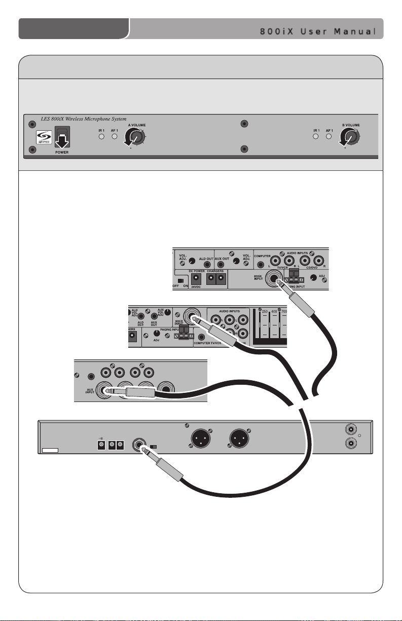
4. CONNECTION TO THE AMPLIFIER
1. Ensure the power switch is in the “OFF” position and all front panel volume controls
are turned fully counter-clockwise.
2. Locate the 1/4”– 1/4” mono cable.
3. Connect the cable from the 1/4” audio output jack on the 800iX to the input
jack on the 880iR, 850iR, or an existing amplier.
850iR Receiver/
Amplier
880iR Receiver/
Amplier
Existing
Amplier
800iX Receiver
14 | 800iX User Manual
Page 19
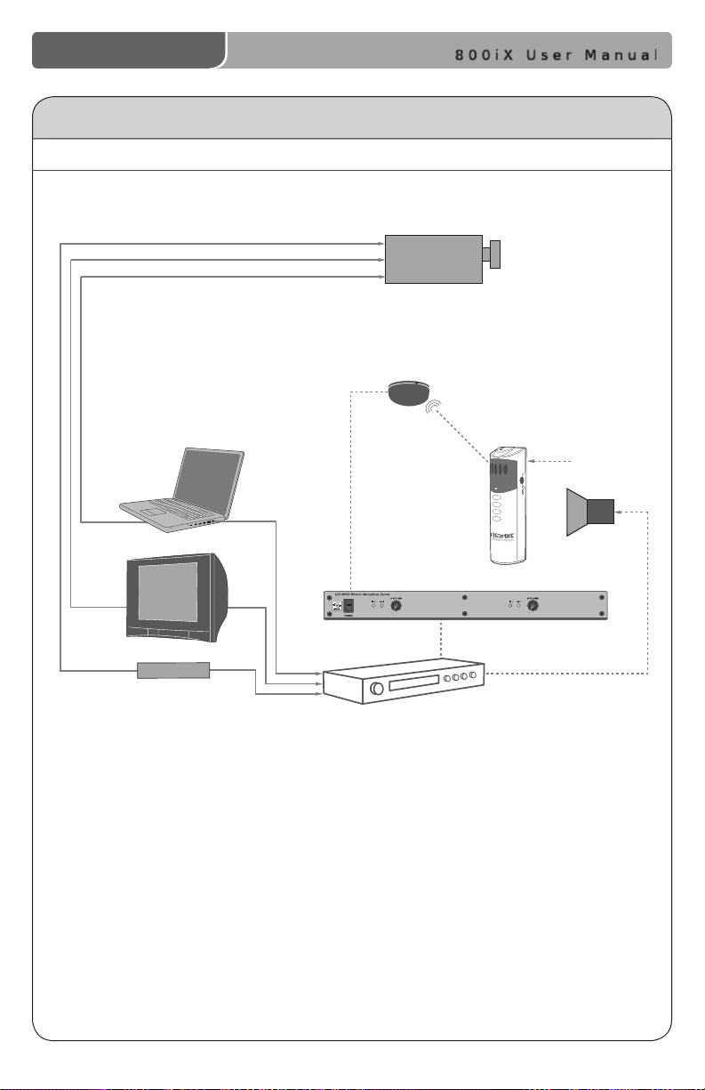
5. AUDIO INTEGRATION
Projector
DVD/VCR
Speaker(s)
IR Sensor
Te acher’s
Microphone
Projector
Audio In
Audio Out
IR Tr ansmission
Video In
Audio Out
Audio Out
Video Out
Video Out
VGA Out
800iX
Existing Amplifier
800iX BLOCK DIAGRAM
800iX User Manual
800iX User Manual | 15
Page 20
800iX User Manual
2.06/2.54
AUDIO OUTPUT
DC POWER
16V/1A
CHARGE
LEVEL
MIC
LINE
CHANNEL A
CHANNEL B
BALANCED
AUDIO
OUTPUTS
+
—
CHANNEL B
SENSOR INPUTS
SHORT
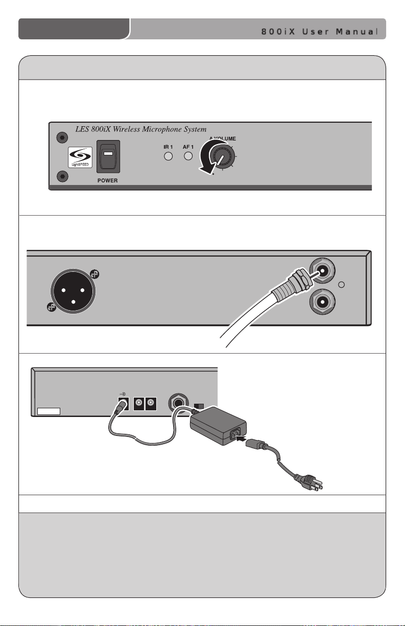
6. FINALIZING CONNECTIONS
4. Ensure the power switch is in the “OFF” position and all front panel volume
controls are turned fully counter-clockwise.
5. Ensure sensor cable is attached securely.
6. Connect DC end of power supply
to the black power jack labeled
“DC POWER.”
7. Connect the black AC power cable
from the power supply to a wall outlet.
FINAL CHECK
1. Ensure all cables are appropriately routed out of walking paths and work areas to
prevent safety hazards to individuals in the room.
2. The amplier packing material should be kept for warranty shipping purposes.
3. Proceed to initial set-up to test system performance.
Leave microphones charging so they are ready for use.
Microphones will need to be charged on a daily basis.
800iX User Manual | 16
Page 21

800iX User Manual
SECTION 3
Initial Set-up, Charging and
Optional Features
17 | 800iX User Manual
Page 22
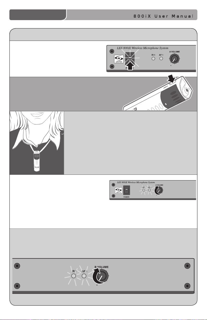
INITIAL SET-UP: REDMIKE
1. Turn the 800iX power switch to the
ON position. The RED LED on the
switch will glow.
2. Turn on the REDMIKE. The RED IR LED on the
800iX will light to indicate a signal is being
received.
3. Slip the REDMIKE with lanyard around the neck
and position the top of the microphone just below
the collarbone. NOTE: Positioning of the REDMIKE is
critical for proper volume adjustment.
800iX User Manual
4. While speaking in a normal voice
slowly increase the volume of the
corresponding channel on the 800iX
until your voice is barely audible.
REMEMBER: This equipment
supplements the user’s voice so they are able to speak in a conversational tone.
Having the volume set too high will result in feedback and listener fatigue.
5. If a second REDMIKE was purchased, repeat steps 2-4. NOTE: Each REDMIKE has
its Channel pre-set to either A or B. No further adjustment is necessary.
800iX User Manual | 18
Page 23
A CH B
OFF
ON
A CH B
OFF
ON
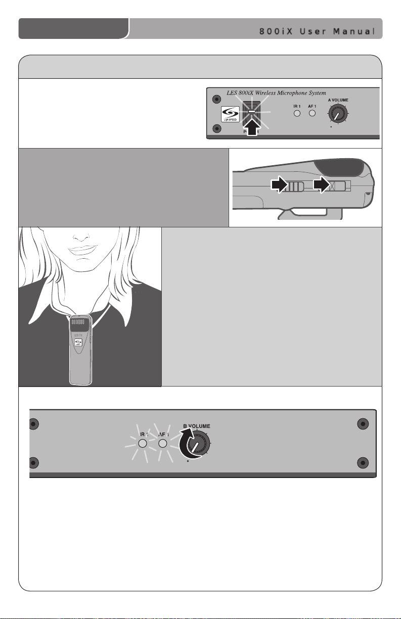
INITIAL SET-UP: OPTIONAL LT-71
1. Turn the 800iX power switch to the
ON position. The RED LED on the
switch will glow.
2. Turn on the LT-71 and set the operating
channel to “B”.
3. Slip the LT-71 with lanyard around the
neck and position the top of the micro-
phone just below the collarbone.
NOTE: Positioning of the LT-71 is critical
for proper volume adjustment.
800iX User Manual
4. While speaking in a normal voice, increase the B VOLUME level until
your voice is barely audible. REMEMBER: This equipment is designed to
supplement and distribute the user’s voice so they are able to speak in a
conversational tone. Having the volume set too high will result in feedback
and listener fatigue.
19 | 800iX User Manual
Page 24
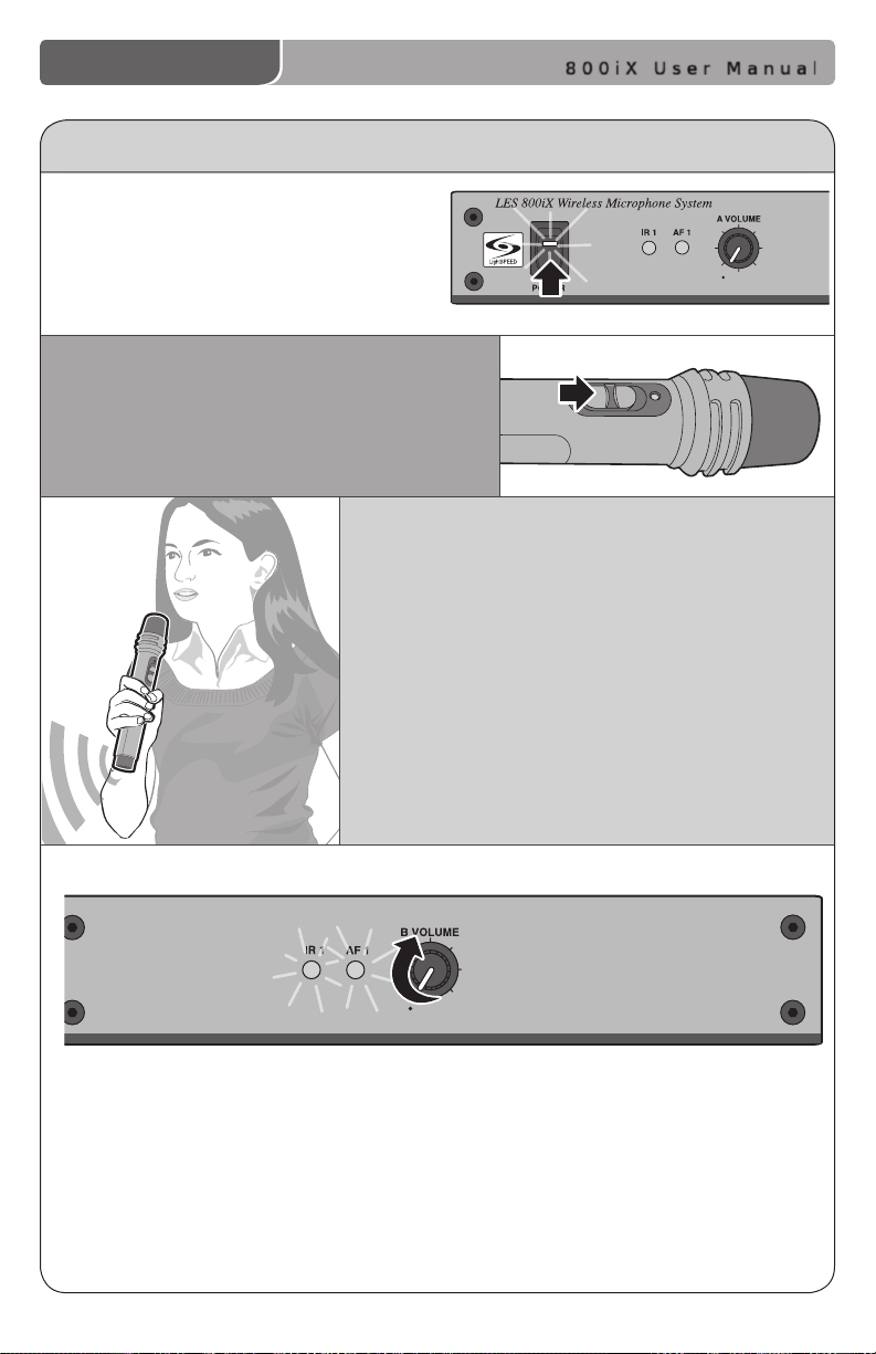
INITIAL SET-UP: OPTIONAL HM-70
1. Ensure the 800iX is ON. The RED
LED on the power switch will glow.
2. Turn on the HM-70 by sliding the switch to
the top position.
3. Grip the barrel in the center section.
Avoid covering the infrared emitters
circling the base. This could interrupt
signal transmission.
800iX User Manual
4. While speaking in a normal voice, increase the B VOLUME level until
your voice is barely audible. REMEMBER: This equipment is designed to
supplement and distribute the user’s voice so they are able to speak in a
conversational tone. Having the volume set too high will result in feedback
and listener fatigue.
800iX User Manual | 20
Page 25
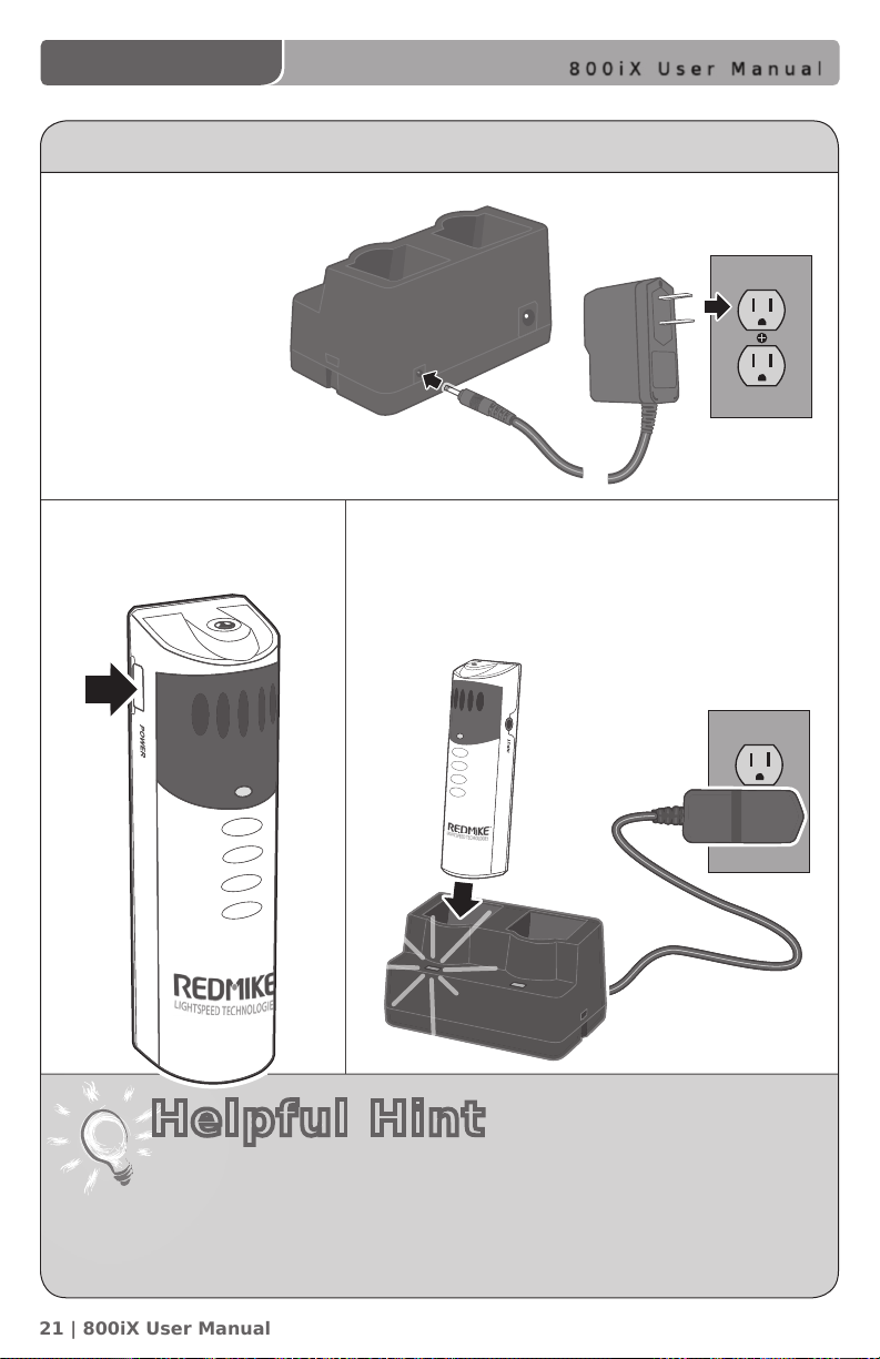
CHARGING THE REDMIKE
1. Plug power cord
into the cradle
charger and
then plug the
AC end into an
electrical outlet.
800iX User Manual
2. Ensure that the REDMIKE
is turned OFF.
Helpful Hint
• REDMIKE incorporates alkaline protection into the microphone design.
Replacement AA NiMH batteries may only be purchased through
Lightspeed Technologies (part # BA-NH2A27).
• A blinking LED indicates a charging error. Be sure to use a Lightspeed
rechargeable sensing battery.
3. Place the REDMIKE into the cradle. The LED on
the cradle will glow RED indicating charging has
started. When the REDMIKE is fully charged
the LED on the cradle charger will change to
GREEN.
21 | 800iX User Manual
Page 26
800iX User Manual
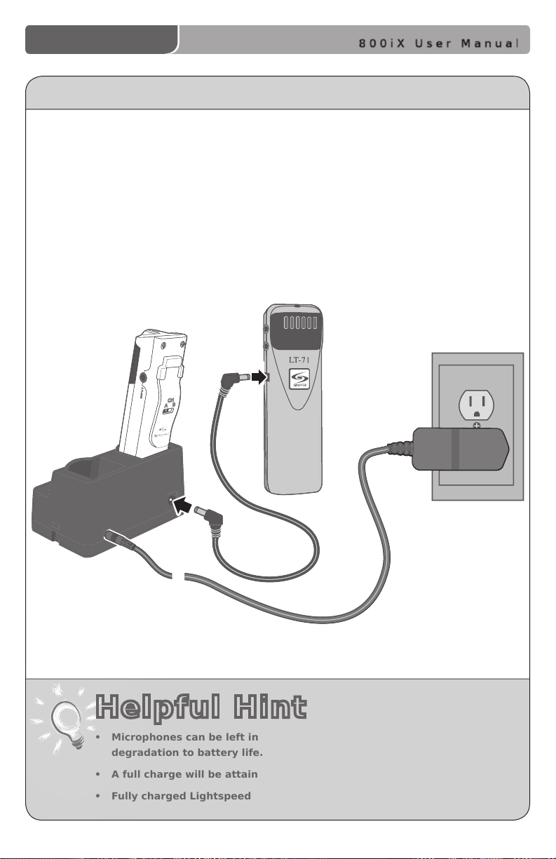
CHARGING THE OPTIONAL LT-71
1. Ensure that the LT-71 is turned OFF.
2. Make sure the cradle charger is plugged into a wall outlet. Connect one end of
the charging cable into the jack labeled CHARGER on the side of the LT-71 and
plug the other end into the charging jack on the rear of the REDMIKE cradle
charger. The LT-71’s rechargeable batteries are factory installed. The LED on the
front of the LT-71 will glow RED when charging.
3. Leave the LT-71 plugged in overnight (8–10 hrs.) to obtain a full charge.
Helpful Hint
• Microphones can be left in the charger for up to two weeks without
degradation to battery life.
• A full charge will be attained in 8-10 hours.
• Fully charged Lightspeed microphones will last over 7 hours.
800iX User Manual | 22
Page 27
800iX User Manual
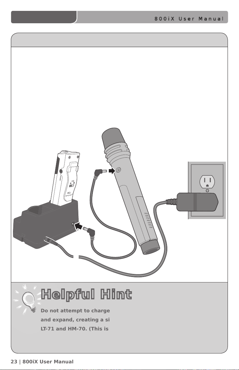
CHARGING THE OPTIONAL HM-70
1. Ensure that the HM-70 is turned OFF.
2. Make sure the cradle charger is plugged into a wall outlet. Connect one end of
the charging cable into the jack labeled CHARGER on the side of the HM-70 and
plug the other end into the charging jack on the rear of the cradle charger. The
HM-70’s rechargeable batteries are factory installed. The LED on the front of the
Handheld Mic will glow GREEN when charging.
3. Leave the HM-70 plugged in overnight (8–10 hrs.) to obtain a full charge. The
GREEN light will turn off when fully charged.
Helpful Hint
Do not attempt to charge alkaline batteries. They can overheat
and expand, creating a signicant hazard and damaging the
LT-71 and HM-70. (This is not covered by the warranty.)
23 | 800iX User Manual
Page 28
800iX User Manual
LT-71
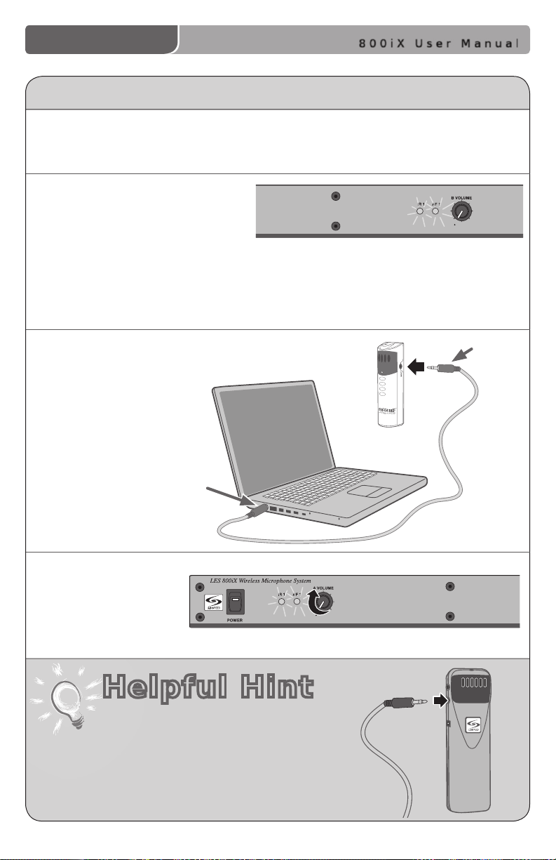
USING THE REDMIKE TO AMPLIFY EXTERNAL AUDIO EQUIPMENT
The REDMIKE includes a 3.5mm audio input jack to connect to an audio source like
a laptop or MP3 player. The REDMIKE will transmit the audio signal to be played
through the system.
1. If your system includes two
REDMIKEs, use the student
microphone (already set to
Channel B). NOTE: This feature
works on both channels but we recommend using Channel B so the teacher’s
volume on the CH A does not have to be adjusted. REMEMBER: It’s easy to
determine which REDMIKE is set to Channel B by speaking into the mic and
watching which set of LED’s glow on the front panel of the 800iX.
2. Plug your laptop, MP3
player or other audio
source into the input on
the REDMIKE labeled
“INPUT” using a 3.5mm
patch cable.
AUDIO
OUTPUT
3. Adjust the volume
of the selected mic
channel to achieve
desired loudness.
Helpful Hint
The optional LT-71 can also amplify external
audio. Simply plug the 3.5mm patch cable
from the audio source into the input labeled
“AUX IN” and adjust the volume of the
source to the desired sound level.
AUDIO
INPUT
800iX User Manual | 24
Page 29

800iX User Manual
SECTION 4
Troubleshooting, Daily Use
and Warranty
25 | 800iX User Manual
Page 30

800iX User Manual
TROUBLESHOOTING GUIDE
Note: Most problems are directly related to low battery power. Please run through the “Battery
Check” items rst. For remaining troubleshooting, use known good, fully-charged batteries.
Battery Check
• Conrm batteries are charged
each night.
• Conrm proper batteries are used.
The REDMIKE requires the Lightspeed
BA-NH2A27 rechargeable sensing
battery for proper charging. The LT-71
& HM-70 require NiMH AA rechargeable
batteries.
• Make sure the microphones are turned
off while charging so a full charge is
attained. Full charge will last eight
hours.
• Inspect the battery contacts. Clean and
adjust if necessary.
Hearing Static
• Ensure sensor is in optimum location
(refer to sensor placement in manual).
A single sensor will cover a 1600 sq. ft.
enclosed classroom.
• Ensure that no other REDMIKE/LT71/
HM70 is operating on the same channel.
Low Volume or Feedback
• Ensure microphone is positioned
appropriately, just below the collar
bone.
• Check volume level on the amplier. If
the volume is too high, feedback will
occur. Adjust accordingly.
No Sound From Speaker
• Turn the 820iR on. Conrm that the
POWER light located on the front panel
switch is on.
• Conrm signal is being received at the
820iR. The IR signal light will be RED
indicating a signal is being received.
• Conrm that REDMIKE is turned on.
There will be a BLUE LED on
the microphone to indicate it is
powered on.
If you review these instructions and still have questions, write down the serial
number and model number of your system and call Lightspeed Technical Services at
800.732.8999, 5 a.m. – 5 p.m., PST.
800iX User Manual | 26
Page 31
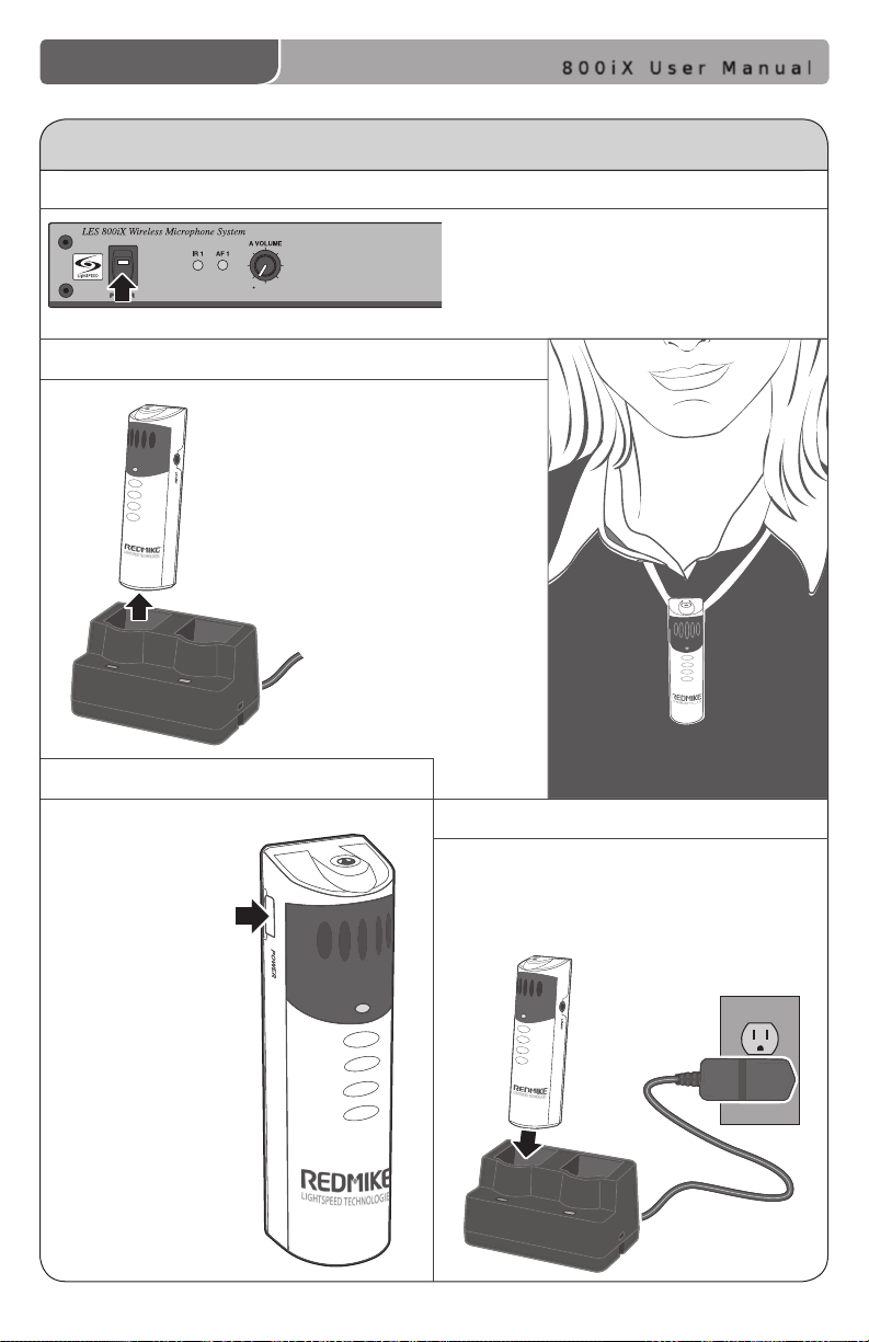
DAILY USE INSTRUCTIONS
1. TURN ON THE 800iX
2. POSITION THE REDMIKE
Remove the REDMIKE from the
charging cradle and place it
around your neck. Adjust the
neck strap so the top of the
microphone rests just below
your collarbone.
800iX User Manual
Ensure the power is switched on.
3. TURN ON THE REDMIKE
Turn the
microphone ON
using the ON/
OFF switch on
the side of the
REDMIKE and
speak normally.
27 | 800iX User Manual
4. CHARGE BATTERIES
Place the REDMIKE back into the
charging cradle to recharge at the
end of the day.
Page 32
800iX User Manual
TIPS ON CLASSROOM AUDIO
Speak in a natural voice. A normal conversational speech level
will provide an adequate signal. It is not necessary to increase
the intensity of your voice—the audio system provides
adequate amplication (approximately 5 – 10 dB) above
1
2
3
4
ambient room noises.
Avoid wearing jewelry that may rub or bump against
the microphone.
Turn the REDMIKE off during private conversations with a student,
parent, or other classroom visitor. You can also cover the LED
lens on top of the REDMIKE to block the signal.
Recharge batteries each night. When recharged nightly, operating
time (actual usage) for the transmitters will last through a typical
school day.
Five-year Limited Warranty
Lightspeed Classroom Audio Systems are guaranteed against malfunction due to defects
in materials and workmanship for a period of FIVE (5) YEARS, beginning at the date of
the purchase invoice. If such malfunction occurs, the product will be repaired or replaced
(at Lightspeed’s option) without charge during the warranty period.
1. Warranty on infrared microphones is FIVE (5) YEARS.
2. Warranty on Lightspeed rechargeable batteries, all external cables and wires provided
by Lightspeed is one (1) year.
3. Prepaid shipping labels are provided by Lightspeed factory or an authorized warranty
service center for warranty repairs.
4. Warranty does not extend to nish, appearance items, or malfunctions due to abuse
or operation other than specied conditions, nor does it extend to incidental or
consequential damages. Repair by other than Lightspeed or its authorized service
agencies will void this guarantee. Information on authorized service agencies is
available from Lightspeed Technologies, Inc.
Our Service Department (800.732.8999, 5 a.m. – 5 p.m., PST)
will handle all your repair/replacement needs.
800iX User Manual | 28
Page 33

800iX User Manual
SYSTEM SPECIFICATIONS
OVERALL SPECIFICATIONS
Standard Carrier Frequencies (IR) ........................ 2.06/2.54 MHz
Alternative Carrier Frequencies (IR) ..................... 3.2/3.7 MHz
Frequency Stability .............................................. ± 3%
Signal-to-Noise Ratio ............................................ > 73 dB
Dynamic Range .................................................... > 73 dB
Frequency Response ........................................... 100 Hz - 10 KHz
RECEIVER SPECIFICATIONS
Receiver Type ....................................................... Superheterodyne
Receiver Sensitivity ..............................................6 µV for 60 dB S/N
Image and Spurious Rejection ..............................> 70 dB
Dimensions (W x D x H) ....................................... 17.3” x 8.5” x 1.75”
Weight ..................................................................5.2 lbs.
TRANSMITTER SPECIFICATIONS
REDMIKE
Audio Distortion ................................................... < 1 %
Built-in Microphone .............................................. Unidirectional Electret
Battery Power (1-year warranty) .......................... 1 AA NiMH Rechargeable
Sensing Battery
Audio Input ..........................................................3.5 mm
Dimensions (W x D x H) ....................................... 0.9” x 1.0” x 3.5”
Weight ..................................................................2.1 oz.
LT-71 LightMic
Audio Distortion ................................................... < 1 %
Built-in Microphone .............................................. Unidirectional Electret
Battery Power (1-year warranty) .......................... 2 AA NiMH Rechargeable
Audio Inputs ......................................................... Mic Level 3.5 mm
Line Level 3.5 mm
Dimensions (W x D x H) ....................................... 1.375” x .75” x 4.625”
Weight ..................................................................3.7 oz.
HM-70 Handheld Microphone
Audio Distortion ................................................... < 1 %
Built-in Microphone .............................................. Unidirectional Electret
Battery Power (1-year warranty) .......................... 2 AA NiMH Rechargeable
Dimensions (W x D x H) ....................................... 2.25” x 2.25” x 8.75”
Weight ..................................................................7.36 oz.
IR SENSOR SPECIFICATIONS
Working Range .....................................................Up to 1600 square feet per sensor
Cable .................................................................... 50 ft., Plenum-rated
Mounting .............................................................. Ceiling clip/Wall bracket
Dimensions .......................................................... 4.25” (Diam.) x 2.0” (H)
Weight ..................................................................4.5 oz.
29 | 800iX User Manual
Page 34

800iX User Manual
INDIVIDUAL COMPONENTS & OPTIONAL ACCESSORIES
Part Number
Description
RX-800
PS-16V-1.0
IR-SR70F
CA-PC50F
RMT
BA-NH2A27
AC-LTCB
BC-RMCC
PS-5V-1.0
Optional Accessories
LT71
HM70
Infrared receiver/amplier/mixer
Power supply/battery charger for 800iX
Infrared sensor with cable and wall or ceiling mounting
bracket
Plenum sensor cable (50 ft.)
REDMIKE classroom microphone
w/lavaliere cord and rechargeable AA battery
Lightspeed AA rechargeable sensing battery
(for REDMIKE)
Lavaliere cord for REDMIKE, LT-71
REDMIKE cradle charger
Cradle charger power supply
LightMic microphone with lavaliere cord, rechargeable
batteries and charging cable
Handheld microphone with rechargeable batteries and
charging cable
MC-TK250LTM
AC-TCC7
AC-800WB
CA-RCA6
CA-RCA24
CA-MSC3535
CA-MMC2535
SPEAKERS
Noise-canceling headset microphone
Charging cable for LT-71 and HM-70 microphones
Wall shelf
6’ dual RCA audio cable
24’ dual RCA audio cable
3.5mm to 3.5mm stereo audio cable
Audio patch cable (2.5 mm mono to 3.5 mm mono)
Contact Lightspeed at 800.732.8999 for speaker
information
800iX User Manual | 30
Page 35

USER NOTES
800iX User Manual
Record your system serial numbers and
purchase information. This is helpful
when ordering additional components,
accessories, and/or warranty service.
Components
800iX
Microphones
Sensors
Speakers
Purchase Information
Your School/Organization
Serial Number
District
Purchase Date
Invoice
31 | 800iX User Manual
Page 36

USER NOTES
800iX User Manual
800iX User Manual | 32
Page 37

USER NOTES
800iX User Manual
800iX User Manual | 33
Page 38

AC-MN800
Lightspeed Technologies, Inc.
11509 SW Herman Rd
Tualatin, OR 97062
800.732.8999
www.lightspeed-tek.com
MK-MN0500908-1
 Loading...