

LightSand S-2500B Installation And User Manual

LightSand, Inc.
Installation and User Manual
for the
S-2500B Gateway
©LightSand, Inc.
279 Sinclair Frontage Road
Milpitas, California 95035
Part Number 004-10004-01
March 2004


Quick Start Guide
The following guide will allow users who are familiar with the LightSand S-2500B Gateway to
quickly set up a new system at a typical installation.
The basic steps are:
1. Log in to the gateway
2. Define the SONET port
3. Define the termination point
4. Define the local interface
5. Verify the FC switches
In addition to the basic procedure, optional commands to set up SNMP monitoring and to
verify the configuration are described below.
Step 1: Log In to the Gateway
Using the supplied serial cable, connect a laptop or other PC to the serial port on the back of
the LightSand Gateway. Use the following port settings:
Bits per second: 9600
Data bits: 8
Parity: None
Stop bits: 1
Flow control: Xon/Xoff
Log in to the gateway with the username: admin, and the password: password. At the CLI
prompt, enter the following command to set up the Ethernet interface:
gateway:> config sys ipaddress <IP-address> <netmask>
where the parameters are the IP address and the network mask of the Ethernet LAN
Management port (for a class C address, the network mask should be 255.255.255.0). If you
need to access the Gateway from a different subnet, you will need to define a default router:
gateway:> config ip default <router-IP-address>
At this point, the LAN port is configured and all remaining steps can be done via Telnet. Exit
the CLI (using the command quit), and disconnect the serial cable.
Quick Start Guide iii

Step 2: Define the SONET port
Connect an Ethernet cable to the LAN Management port, and Telnet to the gateway using the
IP address configured in Step 1. Log in using the same username and password as in Step 1.
Configure the WAN port as SONET with the following command:
gateway:> config port wan 1 type sonet
You will be prompted for timing. If the gateway is to derive the clock from the SONET
equipment (i.e. when connected to an ADM), accept the default line-timing. If the gateway
will be generating the clock, change this value to internal-timing (i.e. when connected back to
back).
Step 3: Define the termination point
Decide if the wide area link will carry FC traffic, IP traffic, or both, then use ONE of the
following options:
FC traffic only
gateway:> config tp pos 1 create ch-c fc
IP traffic only
gateway:> config tp pos 1 create ch-c ip
IP and FC traffic
gateway:> config tp pos 1 create ch-c ip&fc
You will be prompted for several parameters depending on which option you choose. To carry
IP traffic, you will need to enter IP addresses and network masks for the WAN/SONET ports
on both gateways. These addresses must be on the same subnet, and should use addresses that
are not in use in the network. For example, use the addresses 192.168.1.1 and 192.168.1.2 for
the gateways, and use the network mask 255.255.255.0.
You can accept the default responses to the other prompts. If you want to rout IP traffic on the
link, you must enable RIP on this port:
gateway:> config tp pos 1 ip routing-protocol rip
iv S-2500B Gateway

Step 4: Define the local interface
When the wide area link will carry FC traffic
If the wide area connection will be carrying FC traffic, define the local FC interface with the
following command:
gateway:> config port efc 1 type fc
When the wide area link will carry IP traffic
If the wide area connection will be carrying IP traffic, define the local Gigabit Ethernet
interface with the following command:
gateway:> config port efc 2 type ethernet
You will be prompted for the IP address and network mask of the local Gigabit Ethernet port. If
you want to rout IP traffic on the link, you must enable RIP on this port:
gateway:> config port ether 1 ip routing-protocol rip
Step 5: Verify the FC switches
Brocade:
Run licenseShow and verify the presence of the Remote Switch License. Warning: if Remote
Switch License is enabled through the GUI, it will reset the values below.
Run configShow and check the following values
Data Field Size (fabric.ops.dataFieldSize): 2112
Class F Suppression (fabric.ops.mode.noClassF): 0
Buffer Credits (fabric.ops.BBCredit): 7
If no 12000 or 3900 is present, BBCredit should be 7 throughout the fabric. If a 12000 or 3900
is in the fabric, BBCredit should be 4 throughout the fabric. Change the LightSand Gateway’s
BBCredits for the appropriate FC port as follows:
gateway:> config port fc 2 bb-credit 4
Quick Start Guide v

McData:
A McData switch should be configured for open_fabric.
The following two steps are optional:
Step 6: Configure SNMP agent
You may set some basic SNMP information using the following optional commands:
gateway:> config sys name <name>
gateway:> config sys location <location>
gateway:> config sys description <description>
You should use descriptive values for <name>, <location>, and <description>. As soon as the
gateway name has been set, the CLI prompt will change from “gateway:>” to the gateway
name. For example:
gateway:> config sys name Area2
Area2:>
Next, tell the system where to send traps:
gateway:> config snmp trap add X.X.X.X PPPP
where X.X.X.X is the IP address and PPPP is the port number of the SNMP monitoring
system (i.e. the trap receiver). Repeat this command to add multiple trap receivers. If the trap
receiver is not on the same subnet as the LAN management interface, then you need to specify
the default router (see Step 1).
Step 7: Verify the configuration
The following optional commands can be used to show information about the gateway and
verify the setup:
gateway:> show sys all-info
gateway:> show sys all-port
gateway:> show sys all-tp
gateway:> show port sonet 1 info
gateway:> show tp pos 1 info
vi S-2500B Gateway

gateway:> show tp pos 1 ip info (if IP enabled)
gateway:> show tp pos 1 ip rip info (if IP enabled)
gateway:> show port fc 1 info (if FC enabled)
gateway:> show port ether 1 info (if IP enabled)
gateway:> show port ether 1 ip info (if IP enabled)
gateway:> show port ether 1 ip rip info (if IP enabled)
gateway:> show port ether 1 info (if IP enabled)
gateway:> show ip all-routes
gateway:> show snmp trap info
If all configuration parameters look good, the system is ready to operate.
Use the following command to reboot the system while keeping the current configuration:
gateway:> reboot
Use the following command to reboot the system and restore it to the factory default settings:
gateway:> config sys restart cold
Use the following command to shut the system down without rebooting:
gateway:> shutdown
Quick Start Guide vii

viii S-2500B Gateway

S-2500B
Preface
The LightSand S-2500B Gateway enables the extension of Storage Area Networking over
distances of up to thousands of kilometers. The S-2500B is specifically designed for
applications that are critically dependent on dedicated and highly reliable long distance
connectivity, such as disaster recovery, remote site backup, and data-center to data-center
sharing. This manual provides the information necessary to configure and operate your S-
2500B Gateway. Please refer to the separate Installation Guide for instructions on rack
mounting your Gateway.
LightSand reserves the right to make changes to its products or specifications in order to
improve performance, reliability or manufacturability. Specifications herein are subject to
change without notice. While the information contained in this document is held to be accurate
and reliable at the time it was written, it is the responsibility of the user to obtain current
specifications from LightSand.
LightSand will not have any liability for any damages arising from the use of the products in
any high-risk activity, including, but not limited to, the operation of nuclear facilities, aircraft
navigation or communication systems, air traffic control, medical systems, life support or
weapons systems.
LightSand is a registered trademark of LightSand, Inc. All other product or service names used
in this document are for identification purposes only, and may be trademarks or registered
trademarks of their respective companies. All other trademarks or registered trademarks
mentioned herein are the property of their respective holders. Furthermore, the information
contained in this document does not convey to the purchaser of LightSand equipment any
license under the patent right of any manufacturer.
vii

viii S-2500B Gateway

Table of Contents
Quick Start Guide
Step 1: Log In to the Gateway iii
Step 2: Define the SONET port iv
Step 3: Define the termination point iv
Step 4: Define the local interface v
Step 5: Verify the FC switches v
Step 6: Configure SNMP agent vi
Step 7: Verify the configuration vi
S-2500B Preface vii
Chapter 1: Introduction to the S-2500B
Linking Your SAN via SONET 1-1
SONET 1-2
Fiber Channel Over SONET 1-2
IP Over SONET 1-3
Overview of the S-2500B Gateway 1-4
SONET Interface 1-4
IP Routing 1-4
Point to Point Topology 1-5
Chapter 2: System Description
Ports and Indicators 2-1
Software Overview 2-3
CLI 2-3
Graphical User Interface 2-4
Software Restart Modes 2-4
Networking and Connections 2-4
Overview 2-4
LGRP Redundancy 2-5
Gateway Network Management 2-5
Installation and User Manual ix

Standard Connections 2-5
FC Connection 2-6
FC and GbE Connections 2-7
Chapter 3: System Configuration
System Components 3-1
Hardware Installation 3-1
Gateway Setup Procedure 3-2
User Accounts and Privileges 3-2
Assigning an IP Address 3-2
Configuring the Ports 3-4
Establishing a Point to Point Connection 3-5
Creating a Redundant Pair 3-6
Configuring the Node Characteristics 3-6
Configuration for In-Band Management 3-7
Running the SANman GUI 3-8
Table of Contents
Monitoring and Performance 3-8
LED Indicators 3-8
Fault and Performance Monitoring Using the GUI 3-9
Chapter 4: Troubleshooting
Safety Precautions 4-1
Replacing Components 4-2
Access to the System Interior 4-2
Replacing the Power Supplies 4-4
Replacing a Cooling Fan 4-5
Replacing the Cooling Fan Bracket 4-7
Replacing a SCSI Hard Drive 4-8
Replacing the Battery 4-10
x S-2500B Gateway

Table of Contents
Appendix A: CLI Reference
CLI Overview A-1
CLI Access Privileges A-1
Login A-1
Operational Commands A-3
Top Level Operational Commands A-7
Configuration Commands A-8
Configure the System A-9
Configure LGRP Data A-10
Configure SNMP Data A-10
Configure SNMP Trap Data A-11
Configure SNMP Community Strings A-12
Configure a Card A-13
Configure a Port A-14
Configure a Termination Point A-15
Configure System Level IP Channel Data A-17
Configure IP Routing Table Data A-18
Configure Password A-19
Show Commands A-20
Show System Data A-21
Show LGRP Data A-22
Show System Level IP Data A-23
Show IP RIP Data A-24
Show IP ICMP Data A-25
Show Card Data A-26
Show Port Data A-27
Show Termination Point Data A-28
Show User Data A-29
Show SNMP Data A-30
Show Diagnostics A-31
Installation and User Manual xi

Show Configuration A-32
Software Commands A-34
Appendix B: Redundancy
Table of Contents
xii S-2500B Gateway

CHAPTER 1
Introduction to
the S-2500B
Linking Your SAN via SONET
Conventional storage area network (SAN) technology based on Fibre Channel (FC) is limited
in reach to 10 km or less. This is sufficient for most campus or single-location enterprise
applications. As storage needs increase, however, so too does the need to access this storage
over longer distances. Applications such as disaster recovery, dedicated tape backup at a
remote site, and data-center to data-center backup and sharing all exceed the 10 km limit.
In a typical SAN network based on FC communication protocol, FC F_Ports from the fabric
switch are connected to FC N_Ports such as disk drives and host bus adapters that make up the
SAN network. FC E_Ports are used to interconnect FC fabric switches. The 10 km limitation is
primarily due to the link level buffer-to-buffer credit mechanisms employed by FC fabric
devices.
*
The most effective possible means of increasing the distance between switches is to link them
through a dedicated fiber connection. However the installation costs of such a connection are
very high, particularly for distances of tens to hundreds of kilometers that are required by
many remote storage applications.
The most straightforward, practical means to increase the distance between switches is to
terminate them directly onto existing metropolitan area networks or wide area networks using
standard and easily transported protocols. Of the various choices of optical data transport,
SONET offers a number of clear advantages for extending an FC-based SAN. The LightSand
S-2500B Gateway has been optimized to make full use of these advantages for extending
storage area networking.
* For example, the Sound Practices recommendations from the Security and Exchange Commission (SEC) set the
minimum safe distance between primary and backup sites to be between 200 to 300 miles.
1-1

SONET
SONET (Synchronous Optical NETwork) is the system of fiber optic cables, interface and
transport mechanisms that carries data and voice throughout the United States. SONET is the
recognized Telcordia GR-253 standard for the high speed optical transmission of digital
information. SONET is universally distributed, and SONET-based signals are readily passed
from carrier to carrier throughout the country.
A SONET network is typically deployed in a double ring configuration, with one ring serving
as a backup that assumes control within 50 milliseconds if the primary ring fails. Linking to the
network is accomplished by means of add/drop multiplexers (“network elements”) connected
simultaneously to both rings.
SONET defines the network speed of its optical carrier (OC) signals in terms of integer
multiples of a basic rate, 51.84 Mb/s. For example, OC-3 indicates a line rate of 3 times the
basic rate, or 155.52 Mb/s. OC-3 is typically the lowest network speed, and higher rates are
formed by bundling OC-3 channels together in successive groups of 4 to form OC-12, OC-48,
etc. When more bandwidth is required for one single channel, SONET has the ability to
combine several channels into a single rate, which is designated with a “c” for “concatenated.”
Signal processing and switching in SONET are handled electronically (not optically), so data
is converted into light signals for transport after it is first grouped into electronic frames. The
rates for electronic data processing and switching match the optical rates, and are similarly
defined in terms of integer multiples of the basic 51.84 Mb/s rate. Electronic data rates are
designated as the “synchronous transport signal” rate, or STS-n.
SONET is based on synchronous frame communication principals. Data is packaged into
separate frames with a fixed number of bytes at the start of each frame used to synchronize and
control transmission. Data paths are provisioned and remain static. Once data is multiplexed
into the synchronous envelope, it can be transported and switched without having to be
examined or demultiplexed at intermediate points. Each dedicated channel is given a
guaranteed fixed bandwidth for its data.
Fiber Channel Over SONET
The choice of SONET for SAN extension enables the benefits of FC flow control to be
extended between distant sites. The purpose of flow control is to regulate traffic sent to a
congested node. Credit buffering is a vital aspect of traffic control in a FC-based SAN. As
distance (one component of latency) is added to the system, credit buffering becomes an even
more crucial aspect of system design to guarantee that data is never dropped due to congestion.
1-2 S-2500B Gateway

FC uses link level buffer-to-buffer credit buffering to regulate data traffic. Prior to data
transmission, the receiver sends a number of credits to the transmitter (or the transmitter may
start with a default value). Each credit typically represents one FC frame of data. The
transmitter, upon receipt of the credits, has the authority to send data at any time up to the
equivalent number of credits that have arrived from the receiver.
Assuming it is not congested, the receiver immediately replenishes the credits after receiving
data from the transmitter. A well designed system will have sufficient credits to compensate
for the latency between the nodes. Thus, the transmitter will have enough credits in store to
allow the receiver to get the data and then send new credits back before the transmitter runs out
of credits. In this way, data transmission continues at the full rate of the FC link.
Should the final receiving unit become congested, it can exert back pressure against the FC
port simply by not re-supplying credits. The gateway, sensing a lack of credits from the FC
port, creates back pressure against the SONET interface so that the remote gateway can slow
its transmission.
The total round trip transmission time - the latency - in the system is a critical variable in flow
control. This latency has several components, the largest of which is the 5 µsec per km latency
between the two installations (the speed of light in optical fiber).
The LightSand S-2500B Gateway, designed specifically for Fibre Channel over SONET
transport, avoids the unnecessary latency that results from TCP retransmission.
In the critical area of buffer design, the S-2500B Gateway buffers are sized to store an amount
of data equivalent to the need created if full latency is experienced over a full-rate link. Full
rate transmission for the S-2500B can be sustained for up to 2000 km.
IP Over SONET
The consolidation of data in a centrally located domain, data-center to data-center backup, and
similar applications all employ clustered servers both at the local and the remote sites. In
addition to providing backup, a complete SAN extension for these applications is expected to
provide full availability to the remote data through a transparent extension of the LAN.
The same limitations in reliability in the use of conventional IP transport for extending FC also
apply to extending LAN communication. Highly available systems in remote sites require
clustered servers. Clustered servers in turn require a tightly coupled heartbeat signal indicating
operation. This heartbeat signal should not be processed through IP routers, which will drop
data in response to congestion.
Introduction 1-3

The LightSand S-2500B Gateway extends LAN connectivity over SONET via its Gigabit
Ethernet (GbE) port with the same quality of service as used for FC. Data is never dropped due
to congestion, and therefore never needs to be retransmitted. The IP over SONET feature turns
the network backbone into an Ethernet segment of unequaled reliability for attached servers
and clients.
Overview of the S-2500B Gateway
One S-2500B Gateway connects all of the FC switches in one SAN island to another SAN
island. The physical interfaces are SONET (OC-48), Gigabit Ethernet (GbE) and/or Fibre
Channel (FC). Each LightSand S-2500B Gateway is shipped with a set of control software preinstalled, including the CLI (Command Line Interface).
SONET Interface
The SONET interface for the S-2500B Gateway is an industry standard OC-48 signal. This
provides a protected bandwidth allocated between the two point-to-point gateways. The
gateway maps the FC/GbE signals to STS-48c using end-to-end flow control that has been
optimized to provide full FC throughput at OC-48 rates over distances of thousands of
kilometers. A single encapsulation method, FC/POS, is all that is required for transferring data.
FC/POS
The S-2500B Gateway supports direct mapping of FC frames onto SONET, with no
intermediate mapping of FC onto IP. Because all FC frames are directly coupled onto SONET,
the S-2500B is directly connected via SONET to another S-2500B with no intervening IP
routers.
Flow Control
The S-2500B Gateway supports industry standard FC flow control on the FC ports as defined
in NCITS FC-SW-2 and FC-FS.
IP Routing
The S-2500B Gateway provides encapsulation of IP to route native IP traffic. In its function as
an IP router (actually a layer 3 switch), the S-2500B Gateway supports RIPv2.
The S-2500B Gateway has the ability to react to back pressure created by a PAUSE command
issued to the GbE port. The gateway, in turn, creates back pressure across the WAN/SONET
1-4 S-2500B Gateway
link so that the remote gateway can slow its transmission of data. The PAUSE control is in full
compliance with industry standard IEEE 802.3z.
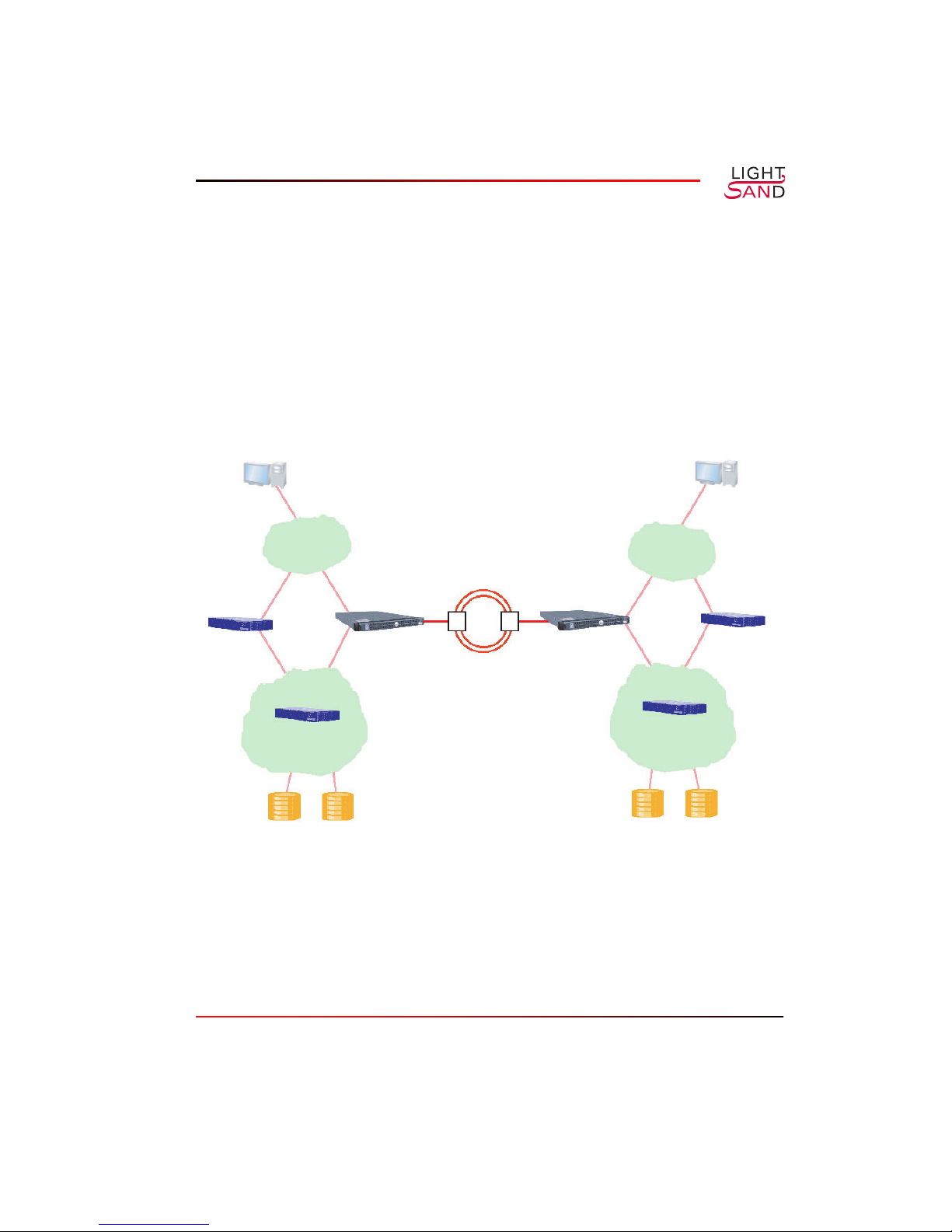
Point to Point Topology
Two S-2500B Gateways are directly connected via a SONET network in a point-to-point
connection. This topology provides the highest performance, since the full bandwidth of the
SONET link is dedicated to the Gateway SAN extension.
Client Client
Server
LAN
FC Switch
SAN
Figure 1-1:
S-2500B
GATEWAY
S-2500B Gateways
SONET
RING
LAN
S-2500B
GATEWAY
Server
FC Switch
SAN
in a Point to Point Topology
Introduction 1-5

CHAPTER 2
System
Description
Ports and Indicators
The diagram below shows the ports and LED indicators on the back panel of the LightSand
S-2500B Gateway. All optical ports use duplex connectors.
WAN
1
FC / GbE
1 2 3
LED
indicators
Figure 2-1:
Ethernet
2 1
S-2500B
2-1
Back Panel
The S-2500B communication ports include the following:
• One WA N (Wide Area Network) port, WAN 1, which is configured to SONET
protocol.
• Three EFC (Ethernet or Fibre Channel) ports, EFC 1, 2 and 3. These can be
configured to FC (Fibre Channel) or GbE (Gigabit Ethernet). These ports are used for
connecting to devices such as fibre channel or GbE switches.
• Ethernet ports 1 and 2. Port 1 is used for connecting to the LAN or out-of-band
network, and Port 2 is used for a possible LGRP link to a redundant gateway.
• One Serial port, which can connect to a computer or console for using the CLI.
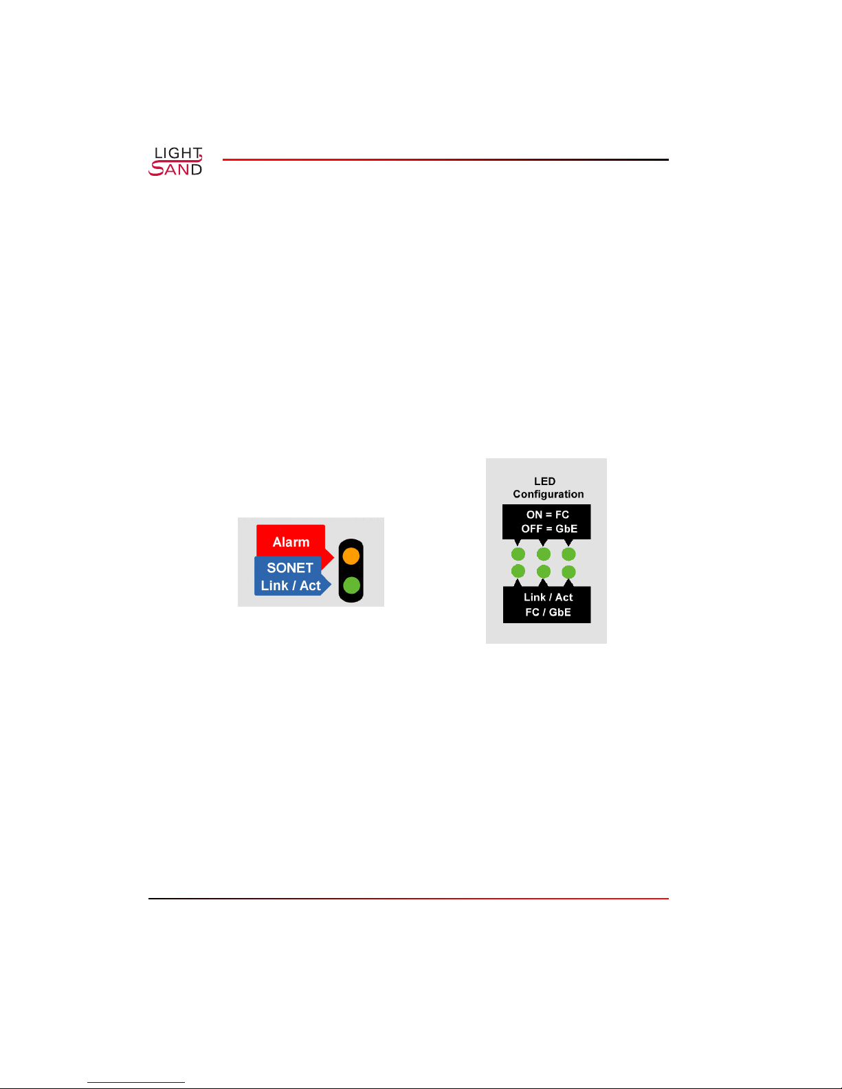
The LED indicators are described by the following label on the S-2500B back panel:
Figure 2-2:
• Alarm: amber means at least one alarm is present of critical or major severity; off
means no significant alarms are present.
• SONET Link/Act: on means the SONET link is enabled; off means disabled.
• ON = FC, OFF = GbE: left to right for Ports 1, 2, 3. On means the port is configured
for FC, off means it is configured for GbE.
• Link / Act, FC / GbE: left to right for Ports 1, 2, 3. On means the link is enabled;
blinking means there is activity on the link; off means the link is disabled.
2-2 S-2500B Gateway
S-2500B
LED Configuration Label

Software Overview
Each LightSand S-2500B Gateway is shipped with a set of control software pre-installed,
which includes the Command Line Interface (CLI).
CLI
The LightSand Command Line Interface allows the user to communicate directly with an
individual S-2500B Gateway (also referred to within the CLI as a system or node). There are
two default accounts provided which have different privileges. The admin account has full
privileges for all types of commands including configuration, showing information, network
management and software commands, while the user account is restricted to viewing
information. Refer to CLI Access Privileges (page A-1).
To establish a CLI session over a serial link between the gateway and a console, connect a
null-modem DB-9 serial cable (supplied with the system) from the serial port on the back
panel of the S-2500B to the serial port of the console. The following settings should be used:
baud rate 9600, no parity, 8 bits, 1 stop bit.
Alternatively, a CLI session can be established using a Telnet connection to the gateway from a
computer on the LAN. The gateway must have an IP address before it can be reached over the
LAN. Refer to the section on Assigning an IP Address (page 3-2).
When a CLI session has been established the following lines will appear (for example):
SWAN OS v1.0.0
login:
Enter a valid account name (defaults are admin and user, which have different privileges). The
password prompt will appear;
Password:
Enter the password. The default password for both accounts is password.
From this point the prompts and available commands will depend upon the privileges assigned
to the user’s account.
System Description 2-3

Graphical User Interface
The SANman Graphical User Interface (GUI) provides graphical tools for managing the
gateway network. For details, please refer to the SANman User Guide.
Software Restart Modes
There are 3 modes for starting or restarting the software on an individual gateway:
• Cold start: The factory-set default configuration is restored and the gateway is
automatically reactivated.
• Warm-inactive start: The previous configuration is restored but the gateway is not
automatically reactivated. The user can take this opportunity to modify some
parameters such as port types. After changes are made the gateway must be explicitly
reactivated.
• Warm-active start: The previous configuration is restored and the gateway is
automatically reactivated. This mode would typically be used after a power failure.
The gateway software can be started in one of these modes using the following CLI
commands: config system restart-mode and config system activate.
Networking and Connections
Overview
The LightSand S-2500B Gateway has been designed to support connections with wide area,
local area and storage area networks, and well as serial connection to a console. The following
describes a typical configuration of the S-2500B Gateway’s ports:
• The wide area network (WAN) port is used for a SONET connection to a remote
gateway.
• The serial port provides a direct link to a console.
• Two Ethernet ports might provide links to the local area network (LAN) or other out-
of-band network, and to another gateway for purposes of redundancy.
2-4 S-2500B Gateway

• One local port might connect to a fibre channel switch, which in turn connects to
devices in a storage area network (SAN). A second local port might connect to a GbE
switch, which in turn connects to the LAN.
LGRP Redundancy
To prevent loss of service due to equipment failure, two gateways can be linked as a pair,
serving as backup for each other, using the LightSand Gateway Redundancy Protocol (LGRP).
For a complete discussion of LGRP redundant pairs, please refer to Appendix B: Redundancy.
(Appendix B is currently under development.)
Gateway Network Management
The SANman graphical user interface, which is shipped with each S-2500B Gateway system,
provides tools for creating a network of gateways (called “nodes”) and for configuring each
individual node. Refer to the SANman User Guide.
Standard Connections
The diagrams in this section show the S-2500B Gateway back panel and cable connections
used in various standard configurations.
System Description 2-5
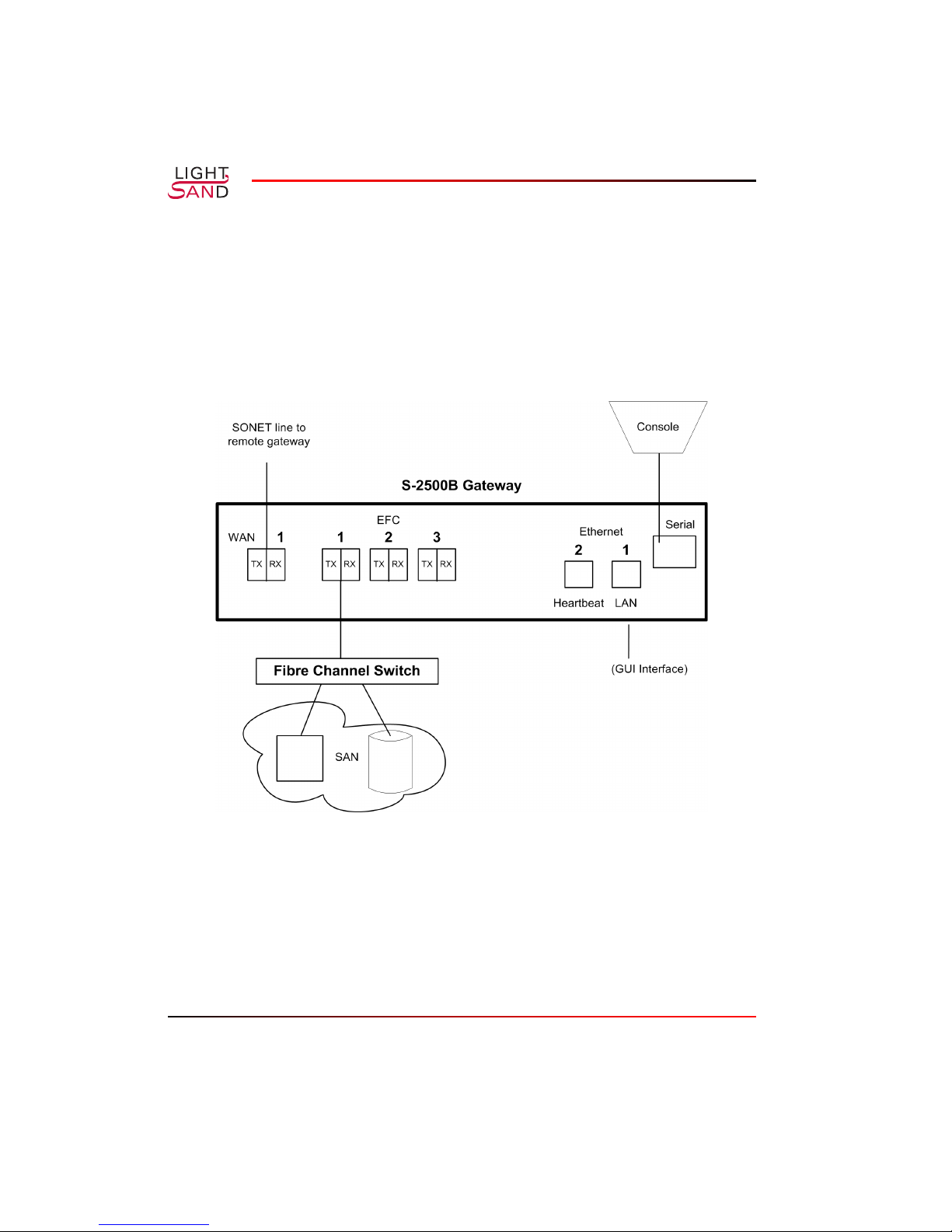
FC Connection
In the simplest configuration the S-2500B is connected through an FC port to a fibre channel
switch, which in turn is connected to devices in a storage area network. The WAN port is used
for a SONET connection to a remote gateway. The serial port supports direct communication
with the gateway from a console. And an Ethernet port provides a link to the local area
network.
Figure 2-3:
2-6 S-2500B Gateway
S-2500B
with Fibre Channel Connection
 Loading...