

Page 1
Page 1 of 6
TX – 30 PROTOCOL TRANSLATOR
Revision 0.2 OWNERS MANUAL 03/02/2005
DESCRIPTION
The TX-30 is a very compact in-line translator which receives USITT DMX-512 signals and transmits the
Lightronics (LMX-128) multiplex protocol. This is the industry standard multiplex protocol. The unit is powered by
the dimmer chain to which it is connected or may optionally be powered by an external plug-in power supply.
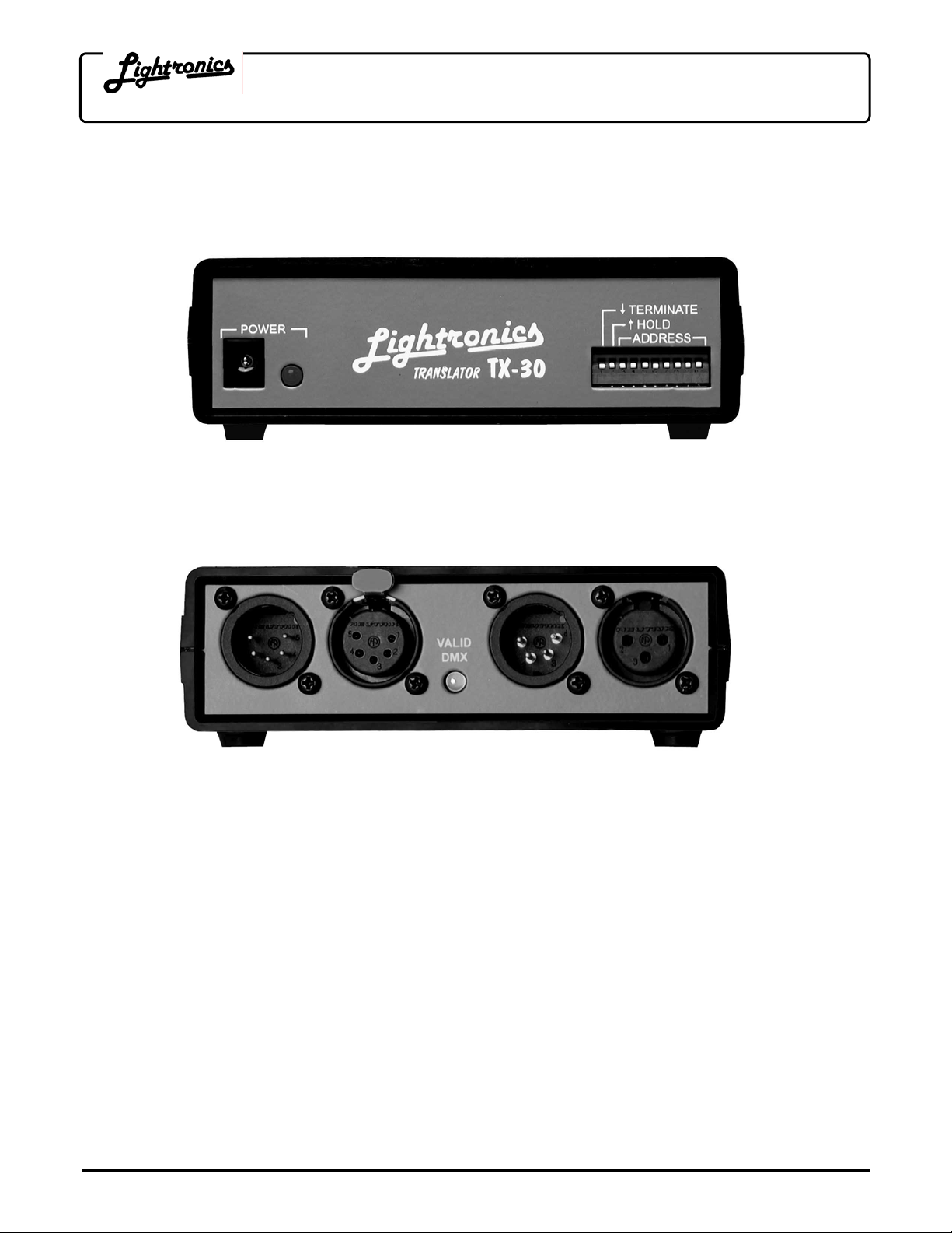
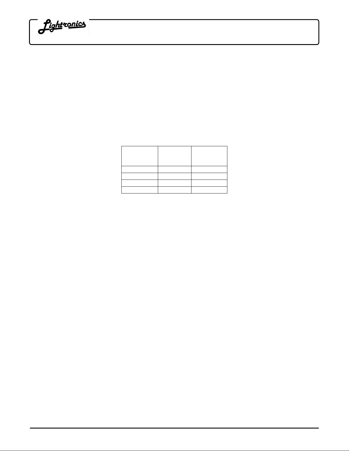
CONNECTIONS
DMX input is received via a 5 pin male XLR connector. LMX output is via a 3 pin female XLR connector. A 5 pin
female XLR is also provided for the DMX signal “pass thru”. LED indicators display power and input signal status.
DMX IN
OPERATION
The TX-30 translates and sends LMX-128 automatically when power is appli ed and a DMX signal is present.
LED indicators show the power and DMX incoming signal status.
CHANNEL ASSIGNMENT
The TX-30 translates 192 channels at a time. Eight of the DIP switches on the front of the unit are used to select
the starting channel of the 192 channel block. When all switches are down, channels 1 - 192 are selected.
Channel selection is incremented two channels at a time. A table of address switch settings is included at th e
back of this manual.
HOLD FUNCTION
DIP switch number 2 activates a "hold" function. If this switch is in the up position, channel outputs will remain at
their current levels indefinitely upon loss of DMX signal.
DMX TERMINATOR
DIP switch number 1 will terminate the DMX input bus when it is in the DOWN position.
www.lightronics.com
Lightronics Inc 509 Central Drive Virginia Beach, VA 23454 Tel 757 486 3588
LMX OUT AMX OUT DMX OUT
Page 2
Page 2 of 6
TX – 30 PROTOCOL TRANSLATOR
Revision 0.2 OWNERS MANUAL 03/02/2005
TX192 OPTION
The TX-30 may be optionally supplied to transmit the AMX-192 protocol. This model transmits both LMX and
AMX simultaneously. An external power supply is included and is needed with this option. The AMX-192 output
signal is transmitted from a 4 pin, male, XLR connector located at the rear of the unit.
CAUTION: Some AMX dimmer equipment uses a 4 pin MINI-DIN connector for the control signal. That
connector is NOT wired the same as the 4 pin XLR connector. The following table provides the information
needed to make an adapter cable.
AMX-192 CONNECTOR WIRING
Signal
Name
Common 1 2
Clock + 2 3
AMX Signal 3 4
Clock - 4 1
EXTERNAL POWER SUPPLY INFORMATION
Input Voltage: 120VAC
Output Voltage: 13.5 VAC
Output Current: 800 Milliamps
Connector: 2.1mm female connector
The TX-30 will operate using an alternative external power supply which can provide anywhere from 13 to 24
Volts AC or DC. The supply must be rated at 600 ma. If a DC supply is used, the center pin of the connector
MUST BE THE NEGATIVE output terminal of the supply.
MAINTENANCE AND REPAIR
TROUBLESHOOTING
Verify the cables (a very common source of problems!).
Ensure that a ll system units are powered - particularly the dimmer to which the translator is connected.
Check address settings at dimmers, console, and translator. Check console patch configuration.
REPAIR
There are no user servicable parts in the unit. Internal service by other than Lightronics authorized agents wi ll
void the warranty. If service is required, contact the dealer from whom you purchased the unit or contact the
Lightronics Service Dept..
XLR
Connector
Pin #
MINI-DIN
Connector
Pin #
www.lightronics.com
Lightronics Inc 509 Central Drive Virginia Beach, VA 23454 Tel 757 486 3588
Page 3

Page 3 of 6
TX – 30 PROTOCOL TRANSLATOR
Revision 0.2 OWNERS MANUAL 03/02/2005
ADDRESS SETTINGS TABLE
The DIP Switch Setting column shows the positions of the DIP switches on the TX-30. The Start Channel column
shows the resulting DMX channel assignment for the first TX-30 LMX output channel (channel 1). The left end
two DIP switches are not included in the table since they do not affect the address settings.
NOTE: Some control consoles and dimmers can be programmed or "patched" to alter their channel order. You
may get unexpected results if you are not aware of the patch condition when you set the TX-30 address switch es.
EXAMPLE: If the dimmer's DIP switches are set to ШШГШГШГГ : the first channel of the dimmer will respond
to console channel 87. The remaining dimmer channels will respond to console channels 88, 89, 90, …etc.
DIP Switch #
and Setting
3 4 5 6 7 8 9 10
ШШШШШШШШ
ШШШШШШШГ
ШШШШШШГШ
ШШШШШШГГ
ШШШШШГШШ
ШШШШШГШГ
ШШШШШГГШ
ШШШШШГГГ
ШШШШГШШШ
ШШШШГШШГ
ШШШШГШГШ
ШШШШГШГГ
ШШШШГГШШ
ШШШШГГШГ
ШШШШГГГШ
ШШШШГГГГ
ШШШГШШШШ
ШШШГШШШГ
ШШШГШШГШ
ШШШГШШГГ
ШШШГШГШШ
ШШШГШГШГ
ШШШГШГГШ
ШШШГШГГГ
ШШШГГШШШ
ШШШГГШШГ
ШШШГГШГШ
ШШШГГШГГ
ШШШГГГШШ
ШШШГГГШГ
ШШШГГГГШ
ШШШГГГГГ
www.lightronics.com
Lightronics Inc 509 Central Drive Virginia Beach, VA 23454 Tel 757 486 3588
Start
Chan
1
3
5
7
9
11
13
15
17
19
21
23
25
27
29
31
33
35
37
39
41
43
45
47
49
51
53
55
57
59
61
63
DIP Switch #
and Setting
3 4 5 6 7 8 9 10
ШШГШШШШШ
ШШГШШШШГ
ШШГШШШГШ
ШШГШШШГГ
ШШГШШГШШ
ШШГШШГШГ
ШШГШШГГШ
ШШГШШГГГ
ШШГШГШШШ
ШШГШГШШГ
ШШГШГШГШ
ШШГШГШГГ
ШШГШГГШШ
ШШГШГГШГ
ШШГШГГГШ
ШШГШГГГГ
ШШГГШШШШ
ШШГГШШШГ
ШШГГШШГШ
ШШГГШШГГ
ШШГГШГШШ
ШШГГШГШГ
ШШГГШГГШ
ШШГГШГГГ
ШШГГГШШШ
ШШГГГШШГ
ШШГГГШГШ
ШШГГГШГГ
ШШГГГГШШ
ШШГГГГШГ
ШШГГГГГШ
ШШГГГГГГ
Start
Chan
65
67
69
71
73
75
77
79
81
83
85
87
89
91
93
95
97
99
101
103
105
107
109
111
113
115
117
119
121
123
125
127
DIP Switch #
3 4 5 6 7 8 9 10
ШГШШШШШШ
ШГШШШШШГ
ШГШШШШГШ
ШГШШШШГГ
ШГШШШГШШ
ШГШШШГШГ
ШГШШШГГШ
ШГШШШГГГ
ШГШШГШШШ
ШГШШГШШГ
ШГШШГШГШ
ШГШШГШГГ
ШГШШГГШШ
ШГШШГГШГ
ШГШШГГГШ
ШГШШГГГГ
ШГШГШШШШ
ШГШГШШШГ
ШГШГШШГШ
ШГШГШШГГ
ШГШГШГШШ
ШГШГШГШГ
ШГШГШГГШ
ШГШГШГГГ
ШГШГГШШШ
ШГШГГШШГ
ШГШГГШГШ
ШГШГГШГГ
ШГШГГГШШ
ШГШГГГШГ
ШГШГГГГШ
ШГШГГГГГ
and Setting
Start
Chan
129
131
133
135
137
139
141
143
145
147
149
151
153
155
157
159
161
163
165
167
169
171
173
175
177
179
181
183
185
187
189
191
DIP Switch #
3 4 5 6 7 8 9 10
ШГГШШШШШ
ШГГШШШШГ
ШГГШШШГШ
ШГГШШШГГ
ШГГШШГШШ
ШГГШШГШГ
ШГГШШГГШ
ШГГШШГГГ
ШГГШГШШШ
ШГГШГШШГ
ШГГШГШГШ
ШГГШГШГГ
ШГГШГГШШ
ШГГШГГШГ
ШГГШГГГШ
ШГГШГГГГ
ШГГГШШШШ
ШГГГШШШГ
ШГГГШШГШ
ШГГГШШГГ
ШГГГШГШШ
ШГГГШГШГ
ШГГГШГГШ
ШГГГШГГГ
ШГГГГШШШ
ШГГГГШШГ
ШГГГГШГШ
ШГГГГШГГ
ШГГГГГШШ
ШГГГГГШГ
ШГГГГГГШ
ШГГГГГГГ
and Setting
Start
Chan
193
195
197
199
201
203
205
207
209
211
213
215
217
219
221
223
225
227
229
231
233
235
237
239
241
243
245
247
249
251
253
255
Page 4

Page 4 of 6
TX – 30 PROTOCOL TRANSLATOR
Revision 0.2 OWNERS MANUAL 03/02/2005
ADDRESS SETTINGS TABLE (CONTINUED)
DIP Switch #
and Setting
3 4 5 6 7 8 9 10
ГШШШШШШШ
ГШШШШШШШ
ГШШШШШГШ
ГШШШШШГГ
ГШШШШГШШ
ГШШШШГШГ
ГШШШШГГШ
ГШШШШГГГ
ГШШШГШШШ
ГШШШГШШГ
ГШШШГШГШ
ГШШШГШГГ
ГШШШГГШШ
ГШШШГГШГ
ГШШШГГГШ
ГШШШГГГГ
ГШШГШШШШ
ГШШГШШШГ
ГШШГШШГШ
ГШШГШШГГ
ГШШГШГШШ
ГШШГШГШГ
ГШШГШГГШ
ГШШГШГГГ
ГШШГГШШШ
ГШШГГШШГ
ГШШГГШГШ
ГШШГГШГГ
ГШШГГГШШ
ГШШГГГШГ
ГШШГГГГШ
ГШШГГГГГ
Start
Chan
257
259
261
263
265
267
269
271
273
275
277
279
281
283
285
287
289
291
293
295
297
299
301
303
305
307
309
311
313
315
317
319
DIP Switch #
and Setting
3 4 5 6 7 8 9 10
ГШГШШШШШ
ГШГШШШШГ
ГШГШШШГШ
ГШГШШШГГ
ГШГШШГШШ
ГШГШШГШГ
ГШГШШГГШ
ГШГШШГГГ
ГШГШГШШШ
ГШГШГШШГ
ГШГШГШГШ
ГШГШГШГГ
ГШГШГГШШ
ГШГШГГШГ
ГШГШГГГШ
ГШГШГГГГ
ГШГГШШШШ
ГШГГШШШГ
ГШГГШШГШ
ГШГГШШГГ
ГШГГШГШШ
ГШГГШГШГ
ГШГГШГГШ
ГШГГШГГГ
ГШГГГШШШ
ГШГГГШШГ
ГШГГГШГШ
ГШГГГШГГ
ГШГГГГШШ
ГШГГГГШГ
ГШГГГГГШ
ГШГГГГГГ
Start
Chan
3 4 5 6 7 8 9 10
321
ГГШШШШШШ
323
ГГШШШШШГ
325
ГГШШШШГШ
327
ГГШШШШГГ
329
ГГШШШГШШ
331
ГГШШШГШГ
333
ГГШШШГГШ
335
ГГШШШГГГ
337
ГГШШГШШШ
339
ГГШШГШШГ
341
ГГШШГШГШ
343
ГГШШГШГГ
345
ГГШШГГШШ
347
ГГШШГГШГ
349
ГГШШГГГШ
351
ГГШШГГГГ
353
ГГШГШШШШ
355
ГГШГШШШГ
357
ГГШГШШГШ
359
ГГШГШШГГ
361
ГГШГШГШШ
363
ГГШГШГШГ
365
ГГШГШГГШ
367
ГГШГШГГГ
369
ГГШГГШШШ
371
ГГШГГШШГ
373
ГГШГГШГШ
375
ГГШГГШГГ
377
ГГШГГГШШ
379
ГГШГГГШГ
381
ГГШГГГГШ
383
ГГШГГГГГ
DIP Switch #
and Setting
Start
Chan
3 4 5 6 7 8 9 10
385
ГГГШШШШШ
387
ГГГШШШШГ
389
ГГГШШШГШ
391
ГГГШШШГГ
393
ГГГШШГШШ
395
ГГГШШГШГ
397
ГГГШШГГШ
399
ГГГШШГГГ
401
ГГГШГШШШ
403
ГГГШГШШГ
405
ГГГШГШГШ
407
ГГГШГШГГ
409
ГГГШГГШШ
411
ГГГШГГШГ
413
ГГГШГГГШ
415
ГГГШГГГГ
417
ГГГГШШШШ
419
ГГГГШШШГ
421
ГГГГШШГШ
423
ГГГГШШГГ
425
ГГГГШГШШ
427
ГГГГШГШГ
429
ГГГГШГГШ
431
ГГГГШГГГ
433
ГГГГГШШШ
435
ГГГГГШШГ
437
ГГГГГШГШ
439
ГГГГГШГГ
441
ГГГГГГШШ
443
ГГГГГГШГ
445
ГГГГГГГШ
447
ГГГГГГГ
DIP Switch #
and Setting
Start
Chan
449
451
453
455
457
459
461
463
465
467
469
471
473
475
477
479
481
483
485
487
489
491
493
495
497
499
501
503
505
507
509
511
www.lightronics.com
Lightronics Inc 509 Central Drive Virginia Beach, VA 23454 Tel 757 486 3588
Page 5

All Lightronics products are warranted for a period of TWO/FIVE YEARS from the date of
purchase against defects in materials and workmanship.
WARRANTY
This warranty is subject to the following restrictions and conditions:
A) If service is required, you may be asked to provide proof of purchase from an authorized
Lightronics dealer.
B) The FIVE YEAR WARRANTY is only valid if the warranty card is returned to Lightronics
accompanied with a copy of the original receipt of purchase within 30 DAYS of the
purchase date, if not then the TWO YEAR WARRANTY applies. Warranty is valid only for
the original purchaser of the unit.
C) This warranty does not apply to damage resulting from abuse, misuse, accidents, shipping,
and repairs or modifications by anyone other than an authorized Lightronics service
representative.
D) This warranty is void if the serial number is removed, altered or defaced.
E) This warranty does not cover loss or damage, direct or indirect arising from the use or
inability to use this product.
F) Lightronics reserves the right to make any changes, modifications, or updates as deemed
appropriate by Lightronics to products returned for service. Such changes may be made
without prior notification to the user and without incurring any responsibility or liability for
modifications or changes to equipment previously supplied. Lightronics is not responsible
for supplying new equipment in accordance with any earlier specifications.
G) This warranty is the only warranty either expressed, implied, or statutory, upon which the
equipment is purchased. No representatives, dealers or any of their agents are authorized
to make any warranties, guarantees, or representations other than expressly stated herein.
H) This warranty does not cover the cost of shipping products to or from Lightronics for
service.
I) Lightronics Inc. reserves the right to make changes as deemed necessary to this warranty
without prior notification.
Page 6

Lightronics Inc. 509 Central Drive Virginia Beach, VA 23454 20050125
 Loading...