

Page 1
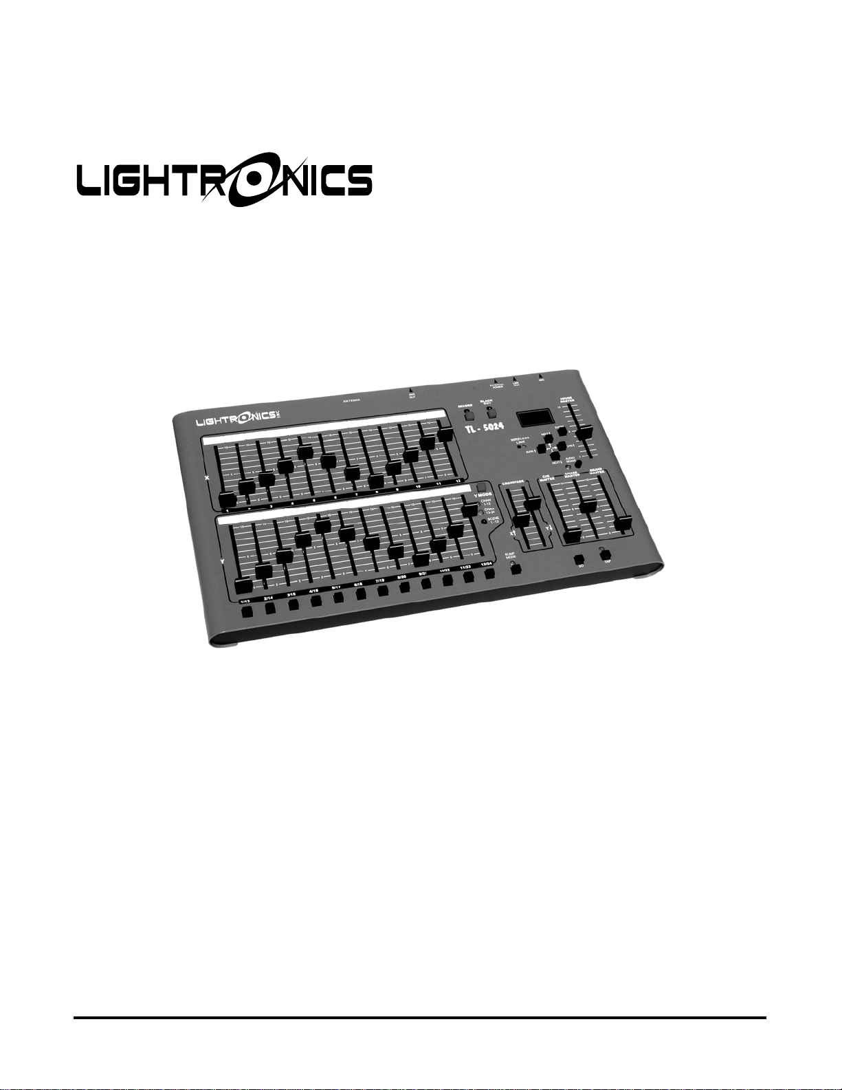
TL - 5024
MEMORY LIGHTING CONSOLE
OWNERS MANUAL
Version 0.93
07/20/2012
www.lightronics.com
Lightronics Inc. 509 Central Drive Virginia Beach, VA 23454 tel 757 486 3588
Page 2
Page 2 of 13
Version 0.93 OWNERS MANUAL 07/20/2012
SPECIFICATIONS
Total channels 12 or 24 depending on mode
Operating modes 12 channels x 2 manual scenes
24 channels x 1 manual scene
12 channels + 12 recorded
scenes
Scene memory 12 scenes per bank x 16 banks
192 total scenes
Chase 12 programmable 20 step chases
Control protocol LMX-128 (3 pin multiplex)
64 channels
USITT DMX-512 optional
256 channels
Output connector 3 pin XLR connector
5 pin XLR for DMX-512
Softpatch 2 programmable pages of 256
DMX dimmers. (128 for LMX)
Compatibility Multiplex protocol compatible
with other multiplexed systems
Power input 18VAC or +15VDC
Optional external power supply
Dimensions 16.25"W X 9.25"H X 2.5"H
Weight 6.8 pounds
CONSOLE DESCRIPTION AND FEATURES
The TL-5024 is a 24 channel lighting control console
which includes advanced features such as multiple
scene banks, softpatching, multiple user
programmable chases, and a LCD Status Display.
The TL-5024 may be powered by the dimmers it is
controlling which eliminates the need for nearby AC
power. The unit may also be powered by an external
power supply (Required for DMX only operation).
The TL-5024 transmits the LMX-128 multiplex lighting
control protocol. This signal is compatible with other
industry standard multiplex signals. The unit can
optionally be factory equipped to transmit the USITT
DMX-512 protocol. The DMX-512 option can be
factory retrofitted to existing units.
The TL-5024 transmits 256 channels of DMX-512
and 64 channels of LMX-128.
www.lightronics.com
Lightronics Inc. 509 Central Drive Virginia Beach, VA 23454 tel 757 486 3588
TL-5024 LIGHTING MEMORY CONSOLE
INSTALLATION
The TL-5024 control console should be kept away
from moisture and direct sources of heat.
LMX CONNECTIONS
Connect the unit to a Lightronics (or compatible)
dimmer using a multiplex control cable with 3 pin XLR
connectors. The TL-5024 is powered by the dimmer
which it is connected to. It may also be powered via
an optional external power supply. The unit will
operate with dimmers in both the NSI/SUNN and
Lightronics modes. All dimmers connected to the unit
MUST be in the SAME
LMX-128 Connector Wiring
PIN # SIGNAL NAME
1 Common
2
Phantom power from dimmers
3 LMX-128 multiplex signal
DMX CONNECTIONS
Connect the unit to a DMX dimmer using a control
cable with 5 pin XLR connectors. The DMX-512
connection does NOT provide console power
therefore an external power supply (provided with
units having DMX option) must be used. There is
more information about external power supplies at
the end of this manual.
DMX-512 Connector Wiring
(5 PIN FEMALE XLR)
PIN # SIGNAL NAME
1 Common
2 DMX data -
3 DMX data +
4 Not Used
5 Not Used
mode.
(3 PIN FEMALE XLR)
Normally +15VDC
Page 3

Page 3 of 13
Version 0.93 OWNERS MANUAL 07/20/2012
TL-5024 LIGHTING MEMORY CONSOLE
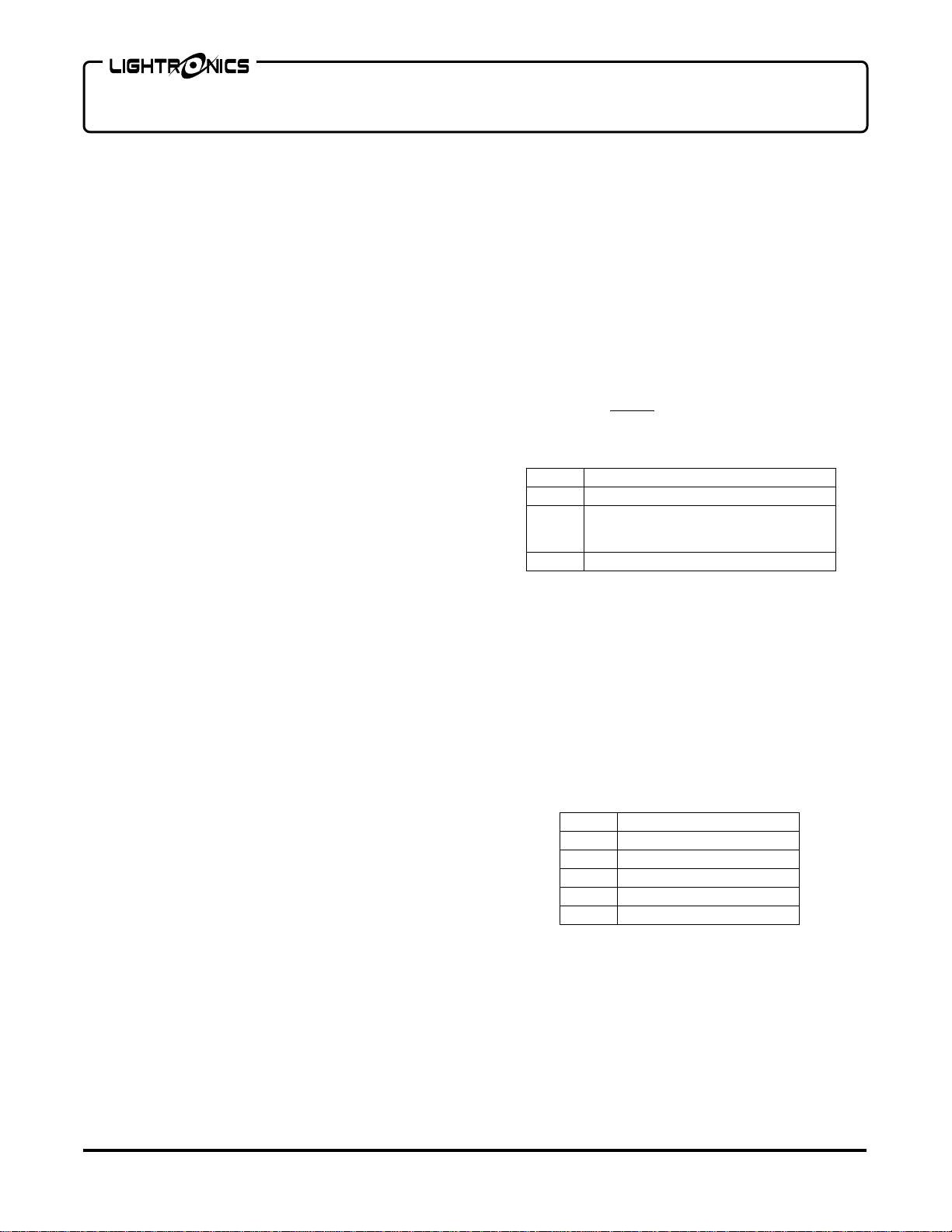
CONTROLS AND INDICATORS
X Faders: Control individual channel levels for channels 1 – 12.
Y Faders: Control level of scenes or individual channels depending on current operating mode.
Cross Faders: Fade between X and Y row faders.
Bump Buttons: Activates associated channels at full intensity while pressed.
TAP Button: Press three or more times at desired rate to set chase speed.
TAP Indicator: Flashes at currently set chase rate.
AUDIO SENSE Knob: Adjusts sensitivity of the microphone for chase rate control.
Y Mode Indicators: Indicate current operating mode of Y faders.
Y Mode Button: Selects operating mode of Y faders.
BLACKOUT Button: Turns on and off console output from all scenes, channels and chases.
BLACKOUT Indicator: Lighted when blackout is active.
Cue Master: Adjusts the intensity of cues.
Chase Master: Adjusts the intensity of running chase patterns.
Grand Master: Adjusts output level of all console functions.
House Master: Adjusts intensity of dimmer channels assigned to console channel number 99.
Record Button: Records scenes and chase patterns.
Record Indicator: Flashes when chase or scene recording is active.
Bump Mode Button: Converts channel bump buttons between pile-on and solo operation.
Bump Mode Indicator: Lighted if bump mode is solo.
GO Button: Activates the next cue in the cue list.
ENTER Button: Activates and executes selections in the menu system.
Arrow Buttons: Select current Scene Bank, Chase Pattern, and number of next Cue. Also used with
the menu system.
X FADERS
Y FADERS
BUMP
BUTTONS
www.lightronics.com
Lightronics Inc. 509 Central Drive Virginia Beach, VA 23454 tel 757 486 3588
Page 4

Page 4 of 13
Version 0.93 OWNERS MANUAL 07/20/2012
SETUP AND PRELIMINARY OPERATION
CONSOLE RESET
The TL-5024 can be set to factory default conditions
by performing an ERASE ALL function which is
accessed from the LCD menu. ERASE ALL
causes the following actions:
1. The cue list will be set to the default values.
2. Chase step scene assignments will be set to the
default scenes. Channel settings will be set OFF.
3. All channels of all scenes in all banks will be set
to zero intensity (scenes will be erased).
4. The softpatch will be set to a one to one
assignment. Patch page 1 will be made active.
OPERATION
OPERATING MODES
The TL-5024 is capable of operating in three different
modes concerning the Y faders. Pressing the "Y
MODE" button changes the function of the Y (lower
12) faders. The selected mode is indicated by the Y
mode LEDs. The X (upper 12) faders ALWAYS
control the level of channels 1 through 12.
z "CH 1-12" In this mode both the X and Y rows of
faders control channels 1 through 12. The cross
faders are used to transfer control between X and Y.
z "CH 13-24" In this mode the Y faders control
channels 13 through 24.
z "SCENE 1-12" In this mode the Y faders control
the intensity of 12 recorded scenes.
GENERAL OPERATION OF CONTROLS
GRAND MASTER: The grand master fader controls
the output level of all functions of the console except
the HOUSE MASTER.
CROSS FADERS: The cross fader provides the ability
to fade between the upper (X) faders and the lower (Y)
faders. The cross fade function is split into two parts
giving you the ability to control the level of the upper
and lower groups of faders individually.
In all modes, the X cross fader must be UP to activate
the upper faders and the Y cross fader must be
DOWN to activate the lower faders.
www.lightronics.com
Lightronics Inc. 509 Central Drive Virginia Beach, VA 23454 tel 757 486 3588
TL-5024 LIGHTING MEMORY CONSOLE
BUMP BUTTONS: These momentary buttons
activate channels 1 through 12 at full intensity when
pressed. The master fader affects the level of
channels activated by the bump buttons.
Bump buttons are not latching. When you release a
bump button the associated channel returns to its
previous state.
BUMP MODE BUTTON: The bump buttons may be
operated in 2 different modes (pile-on and solo).
This button switches between these modes. In the
pile-on mode pushing a bump button will force the
associated channel to full intensity overriding the
channel fader setting. In the solo mode the bump
buttons force the associated channel to full intensity
AND force all other channels off.
CHASE MASTER FADER: The chase master
controls the overall intensity of chase patterns.
CUE MASTER FADER: The cue master fader
controls the overall intensity of scenes activated by
the cue list.
BLACKOUT BUTTON: Pressing the blackout
button causes all channels, scenes, chases, and
cues to go to zero intensity. The blackout LED will
light whenever the console is in blackout mode.
TAP BUTTON: Press 3 or more times at the
desired rate to set chase speed. TAP LED will flash
at the selected rate.
RECORD BUTTON: Executes recording of scenes
and chase patterns. RECORD LED will light when in
recording is active.
HOUSE MASTER FADER: The house master is an
extra channel fader which will control the intensity of
any/all dimmer channels assigned as console
channel 99.
It is used to enable control of the house lights from
the lighting console in situations where the house
lights are included in the dimmer system.
Page 5
Page 5 of 13
Version 0.93 OWNERS MANUAL 07/20/2012
TL-5024 LIGHTING MEMORY CONSOLE
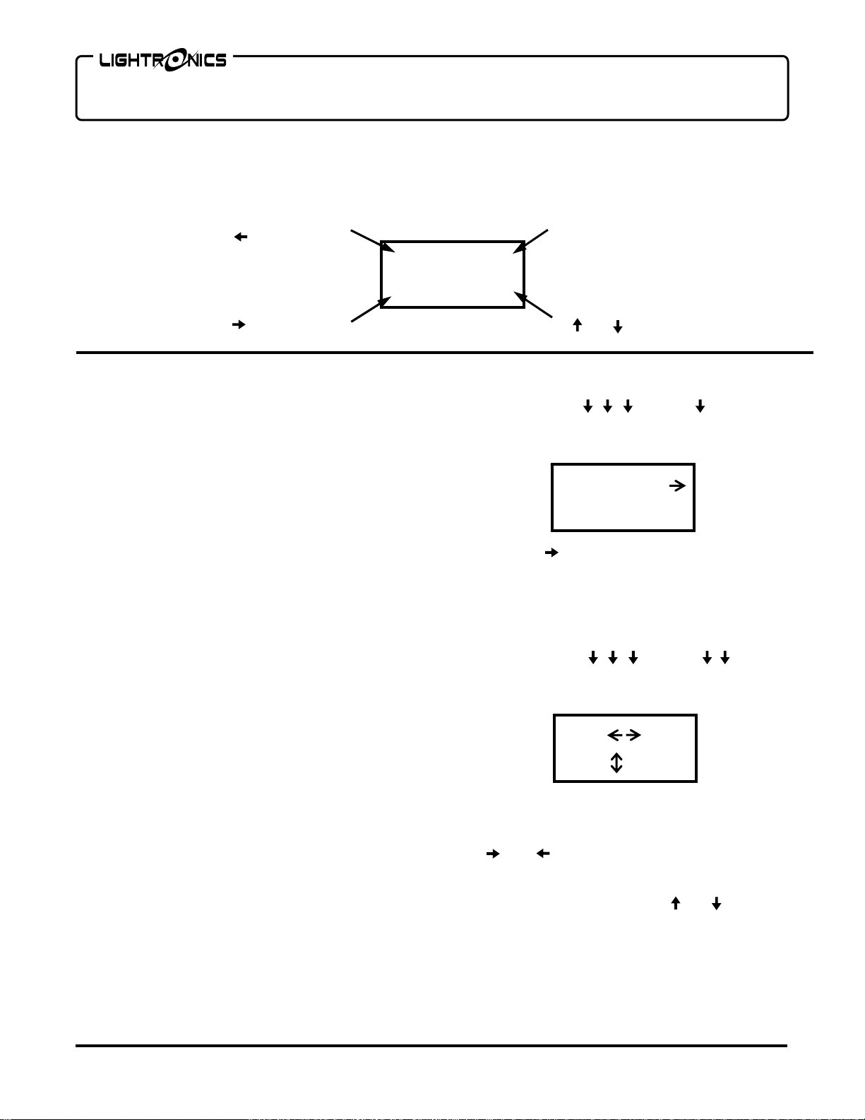
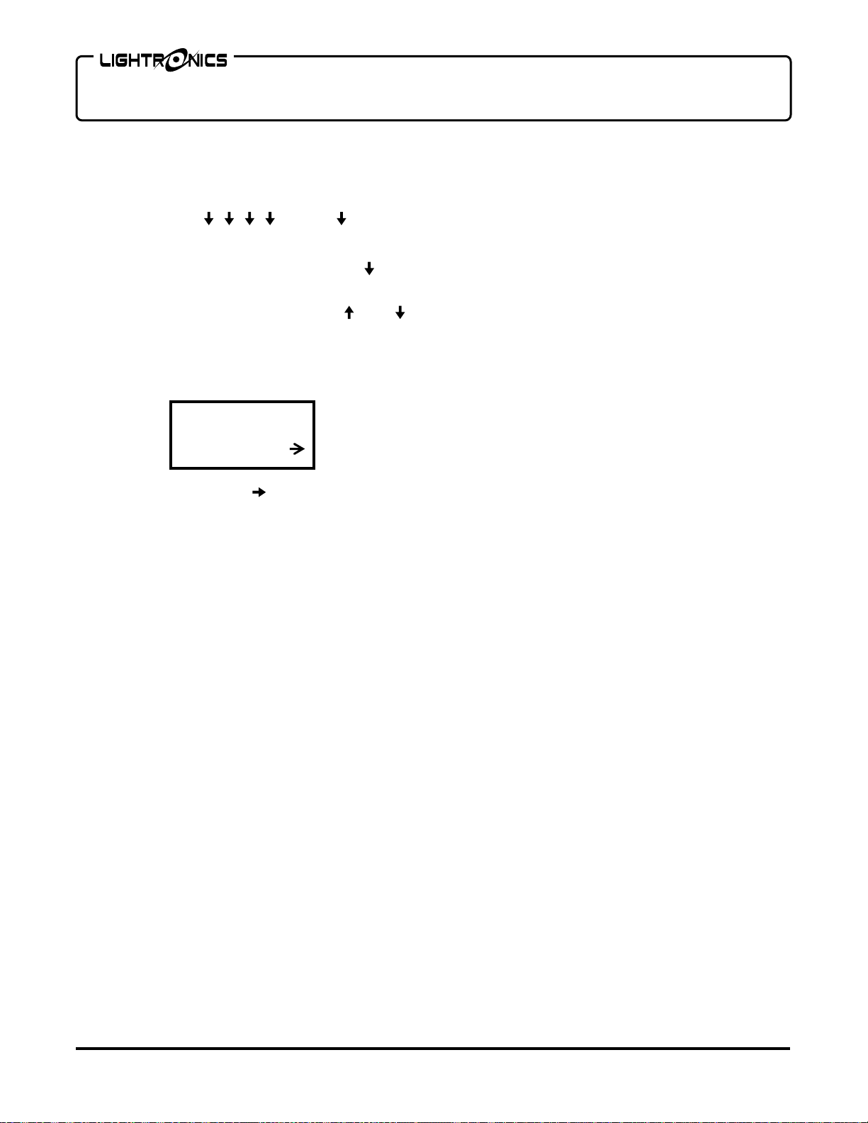
STATUS DISPLAY
The diagram below shows what information is given on the status display during normal opera tion. When the
menu system is in use then other information will be shown.
Current Scene Bank (1 - 16)
Use to change
Current Cue (0 - 240)
B01 Q000
Current Chase Pattern (1 - 12)
Use to change
C01 N001
Next Cue (0 - 240)
Use and to change
CHANNEL ASSIGNMENTS (PATCHING)
You can assign dimmer channels to console channels
in other than a 1 to 1 correspondence. For instance
you may want to have the lights connected to dimmer
channels 1 and 2 assigned to console fader 3. (You
can have several dimmer channels patched to a single
console fader but you cannot assign a dimmer channel
to more than 1 console channel at a time.) This set of
channel assignments or “patch” information can be
saved in the console as a “patch page”.
PATCH PAGES
The TL-5024 contains 2 patch pages. In other words
you can have two complete sets of channel
assignments in the console and switch between them.
In situations where the console is used for different
applications, multiple patch pages can save time that
would be spent re-patching each channel for a given
application. The current patch page may be toggled
between the two pages by using the MENU system.
DEFAULT CHANNEL ASSIGNMENTS
The TL-5024 is provided with a default channel
assignment set for patch page 1. This assignment
results in a 1 to 1 patch for dimmer channels 1 - 24.
The pattern is repeated beginning at dimmer channel
25 (It is assigned to console channel 1 again). The
repeat continues up to dimmer channel 256.
The default for patch page 2 is all channel
assignments completely cleared.
www.lightronics.com
Lightronics Inc. 509 Central Drive Virginia Beach, VA 23454 tel 757 486 3588
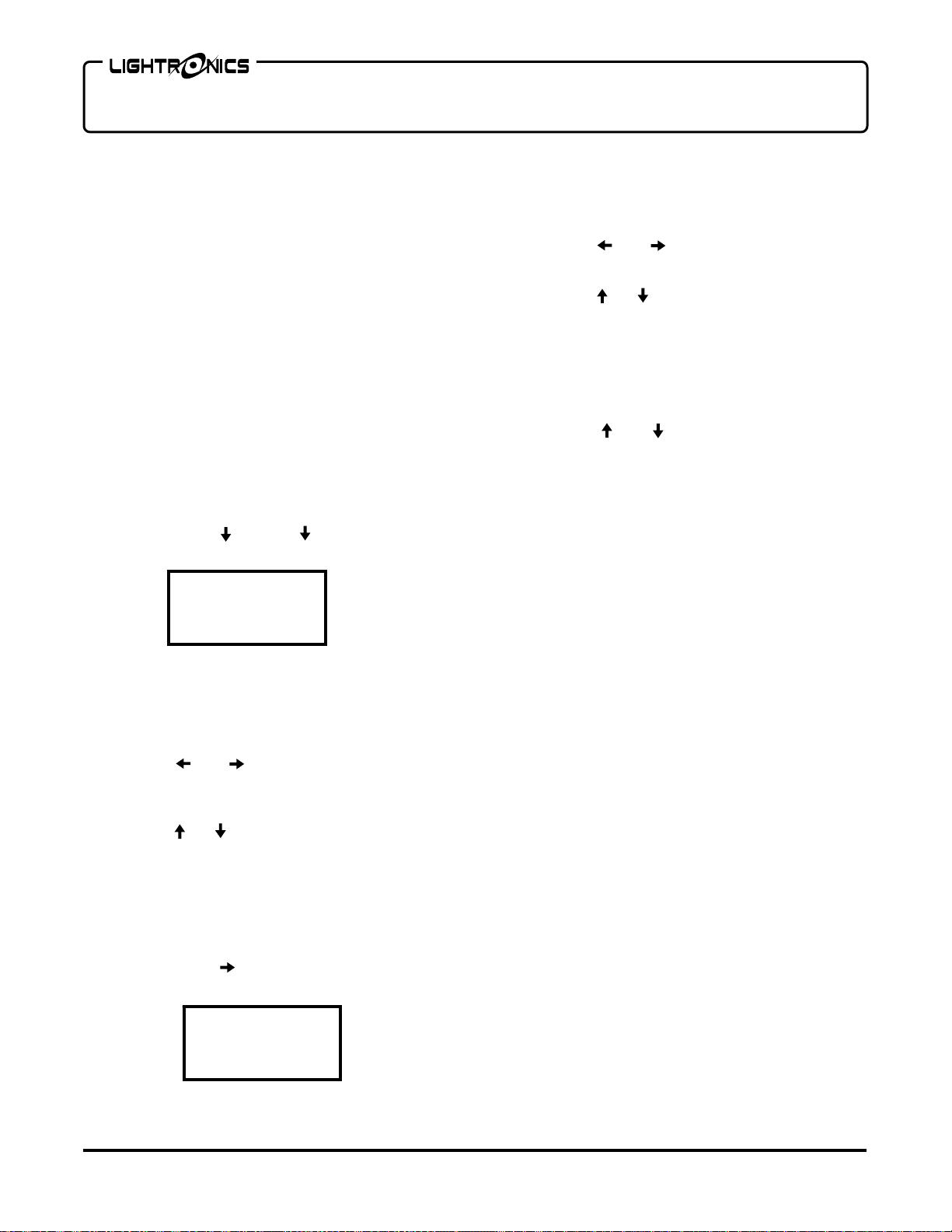
TO CHANGE THE CURRENT PATCH PAGE
1. Push ENTER ENTER to access
the PATCH submenu. The following display will
appear with the page number (1 or 2) flashing.
PAGE=1
REPATCH
2. Use the button to change the number.
ASSIGNING CURRENT PATCH PAGE CHANNELS
Channel assignments are always applied only to the
currently selected patch page.
1. Push ENTER ENTER ENTER
to access the REPATCH submenu. The following
display will be shown.
DIM 001
CON 01
The top row shows a dimmer channel number. The
bottom row shows the console channel (fader) to
which the dimmer channel number is assigned. Use
the and buttons to cycle through the dimmer
channel numbers. The assigned console channel
will be shown for each one. You can change the
console channel number with the and buttons.
You can assign more than one dimmer channel to
any console channel. A dimmer channel cannot be
assigned to multiple console channels. In other
words - any particular dimmer can be assigned to
only one console channel.
Page 6

Page 6 of 13
Version 0.93 OWNERS MANUAL 07/20/2012
You can assign a dimmer channel to console channel
00. If you do this, then that dimmer channel will not
respond to the console.
You can also assign a dimmer channel to console
channel 99. If you do this, then the dimmer channel
will be controlled by the HOUSE MASTER fader.
Multiple dimmer channels can be assigned to the
house master.
You can perform three other operations from the
PATCH menus.
1. You can copy the contents of either patch page to
the other one.
2. You can set a 1 to 1 patch condition for the
current page.
3. You can ZERO ALL channel assignments for the
current patch page. This removes ALL
assignments.
RECORDING SCENES
The TL-5024 can store 192 scenes. Each scene
contains all 24 channels. The scene memory is
organized as 16 banks with 12 scenes in each bank.
To record a scene:
1. Select the bank into which the scene will be
stored by pushing the button. The current
scene bank is shown in the upper left corner of
the LCD STATUS display and advances as the
button is pushed.
2. Set the faders to the desired intensities for the
scene (create the scene).
3. Push the RECORD button. The RECORD
indicator will begin flashing.
4. Push one of the 12 bump buttons (below the
lower fader row) to store the scene. The number
of the button pushed (1-12) is the scene number
within the bank selected in step 1. The
record indicator will go off.
SCENE PLAYBACK
1. Select the bank for the scene you want to
activate by pushing the button. The current
scene bank is shown in the upper left corner of
the LCD STATUS display and will advance as the
button is pushed.
www.lightronics.com
Lightronics Inc. 509 Central Drive Virginia Beach, VA 23454 tel 757 486 3588
TL-5024 LIGHTING MEMORY CONSOLE
2. Activate the SCENE 1-12 mode for the Y
faders.
3. Raise a Y fader (1 - 12) to activate its
associated scene in the bank. Multiple scenes
may be added together by raising more than 1
fader.
CHASER FUNCTIONS
A chase is a sequence of complete scenes which
runs, automatically, at a user selected speed. The
scenes must be created and stored in the unit scene
memory before use. The channels in each scene
will appear at the recorded intensity when the chase
is played.
A chase may also be a sequence of specific
channel selections to be on for each step.
The TL-5024 provides 12 chases. Each chase may
have up to 20 steps. All steps of all chases are user
created. Combinations of scenes and channel
settings may be used in chase steps.
DEFAULT CHASE SETTINGS
The TL-5024 has a default set of scene
assignments and channel intensities for chase
operations. These are the assignments which will be
set if the ERASE ALL or ERASE CHASER functions
are invoked from the ERASE menu.
Default scene assignments for chase steps are set
to the first 12 scenes in each bank starting at bank
01. In other words chase 01 uses the first 12 scenes
in bank 01. Chase 02 is set to the first 12 scenes in
bank 02. Chase steps beyond step 12 are set to
"END" which means that the chase will "wrap
around'" back to the first step after step 12. You
can program any chase to use all 20 steps if
needed.
A complete table of default chase step assignments
is provided at the end of this manual.
RECORDING CHASES
1. Push ENTER ENTER to access the
CHASER submenu. The following display will
appear.
C01 S01
EDIT
Page 7

Page 7 of 13
Version 0.93 OWNERS MANUAL 07/20/2012
The chase which is to be programmed is shown in the
upper left (C01 meaning chase 01). The step number
within the chase is shown in the upper right (S01
meaning step 01). The item on the bottom row (EDIT)
will access a submenu enabling you to edit that
chase/step number.
Use the and buttons to select one of the
choices. The choice will flash when selected. For
the chase number and step number - use the
and buttons to change the number.
2. Push ENTER when EDIT is selected to program
or edit the contents of the chase step. The
following display will appear:
BNK:SCN
01:01
3. Use the a nd buttons to change the step to
another bank:scene number. You can select
bank 00:scene 00. This selection will cause all
scenes to be off for the step.
You can force the chase to start over (wrap
around) at any given step by pushing the
button until END appears.
4. You can also select individual channels to be ON
or OFF for the chase step by push the button.
The following display will appear:
CHN:01
OFF
Use the and buttons to cycle through the
channels (1 - 24) and use the and buttons to
turn the channel ON or OFF for the step.
Channels turned on from this menu will override any
scene settings for the channel when the chase is
played.
CHASE PLAYBACK
1. The currently selected chase is indicated in the
lower left section of the LCD STATUS display.
Use the button to change to another chase.
www.lightronics.com
Lightronics Inc. 509 Central Drive Virginia Beach, VA 23454 tel 757 486 3588
TL-5024 LIGHTING MEMORY CONSOLE
You can turn off the chaser function by selecting
chase 00. The TAP LED will not blink when chase
00 is selected.
2. Push the TAP button 3 or more times at the
same rate that you want the chase to run.
3. Raise the CHASE MASTER fader to make the
chase visible at the lights. Chases are added
into manual fader settings and active scenes.
AUDIO DRIVEN CHASE
The chase rate may be controlled by an internally
mounted microphone. The microphone picks up
sounds nearby and circuitry in the TL-5024 filters
out all but low frequency sounds. The result is that
the chase will synchronize with base notes of music
being played nearby.
Rotate the AUDIO SENSE control clockwise to
increase the sensitivity of the microphone. This
function is disabled when AUDIO SENSE is turned
fully counterclockwise.
USING CUE LISTS
After you have created and saved scenes in the TL-
5024, you can put them into a scene cue list. Once
the cue list has been created, you can “play” the list
by pushing the GO button. Pushing this button
causes the current cue scene to fade out and the
next scene to fade in.
The list contains 240 cues. Any cue may point to
any scene in any bank. Each entry in the cue list
contains the bank number of a scene, the scene
number within that bank, a “fade in” time , and a
“fade out” time. The “fade out” time is the number of
seconds the PREVIOUS cue scene will take to fade
out as the current cue scene fades in. You can
adjust both of these times to obtain various effects.
Valid fade times can range from 1 to 99 seconds.
The overall brightness of cues is controlled by the
CUE MASTER fader. Cues are affected by the
BLACKOUT function and the GRAND MASTER
fader. Cue number 0 is reserved as a blackout and
is not programmable.
The LCD STATUS display always shows the current
cue number in the upper right section and the next
cue number in the lower right. Cues normally
proceed in a sequential manner (cue 2 follows cue
1… etc.). You can alter the order of cue playback
by using the and buttons.
Page 8
Page 8 of 13
Version 0.93 OWNERS MANUAL 07/20/2012
The display indicates your entry as the next cue to be
activated. When you push GO – this cue will fade in.
DEFAULT CUE LIST
The TL-5024 is provided with a factory default cue list.
This is the condition which will be set if the ERASE
ALL or ERASE CUEING function is invoked from the
ERASE menu. The settings for the default cue list are
as follows:
Cues 1 - 12 are set to scenes 1 - 12 in scene bank 1.
Cues 13 - 24 are set to scenes 1 - 12 in scene bank 2.
Cues 25 - 36 are set to scenes 1 - 12 in scene bank 3.
This repeat continues until all 16 scene banks have
been used. This occurs at cue number 192. Cues
193 through 240 are set to scene bank 0, scene 0. In
other words they are not assigned.
CREATING A CUE LIST
1. Push ENTER ENTER to access the cueing
menu. The following Display will be shown.
CUE BK01
001 SC01
The left side of the display shows the cue number
being assigned. The upper right shows the bank
number of the scene assigned to that cue. The lower
right shows the scene number (within the bank)
assigned to that cue.
2. Use the and buttons to select one of the
items (cue number, bank number, or the scene
number). The item will flash when selected.
3. Use the and buttons to change the value of
the selected item.
To review cue assignments: Select the cue number
and run it up and down. The bank/ scene assigned
will be displayed as you cycle through the cues.
4. To set the "fade in" and "fade out" times for the
cue: Push the button until the following
display appears:
CUE FI02
001 FO02
www.lightronics.com
Lightronics Inc. 509 Central Drive Virginia Beach, VA 23454 tel 757 486 3588
TL-5024 LIGHTING MEMORY CONSOLE
The cue number is shown on the left side of the
display. The right side shows the fade in time in
seconds on the top and the fade out time in seconds
on the bottom.
5. Use the and buttons to select either FI or
FO. The item will flash when selected.
6. Use the and buttons to change the value of
the selected item. The unit will not accept a
fade time of 00.
CUE LIST PLAYBACK
1. The next cue to be activated is shown in the
lower right section of the LCD STATUS display.
Use the and buttons to change the next
cue selection.
2. Push the GO button. The next cue (selected in
the step above) will be activated.
The overall intensity of cues is controlled by the
CUE MASTER fader. Cues will not be visible if the
CUE MASTER fader is down.
Individual channel fader settings and scenes are
added into the cue in a "greatest of" manner. In
other words if the cue sets a channel at 50% and
the fader for that channel is at 100% then the
resulting intensity for that channel will be 100%.
ERASE FUNCTIONS
Erase functions are used to partially or fully reset
the TL-5024 to it's default (factory set) state. They
can be invoked separately or as a group. There are
four functions as follows:
1. ERASE CUEING: Returns the cue list to its
default set of banks, scenes, and fade times.
The current and next cue numbers are not altered.
2. ERASE CHASER: Returns the chase step
assignments to the default set of banks,
scenes and channel settings. The current
chase number will not be altered.
3. ERASE SCENES: All channels of all scenes in
all banks will be set to zero intensity. The
current bank number will not be altered.
4. ERASE SOFTPATCH: Patch page 1 will be
set to a 1 to 1 assignment and will become
the active page. Patch page 2 will be
completely cleared of all assignments.
Page 9
Page 9 of 13
Version 0.93 OWNERS MANUAL 07/20/2012
5. ERASE ALL: Performs all 4 of the erase
functions described above.
USING ERASE FUNCTIONS
1. Push ENTER ENTER . The
display will show the ERASE CUEING menu.
2. Push ENTER to erase the cues. or Push to
move to the next erase function.
Once in the erase menus you can use the and
buttons to cycle through all of the erase function
choices. When you activate an erase function you will
see a display (shown below) which allows you to back
out without actually completing the erase function.
Are You
Sure? N
The N means NO. Use the button to change it to Y
(yes) and push ENTER. The function will proceed.
DMX OPERATION
If the DMX option is installed in the TL-5024 it will
transmit both DMX and LMX signals simultaneously.
The DMX-512 connection does NOT provide console
power therefore an external power supply (provided
with units having the DMX option) must be used.
TL-5024 WIRELESS OPTION
The TL-5024 can optionally be provided with an
internal RF transmitter module which transmits the
DMX-512 control signal. It can operate with multiple
compatible wireless DMX dimmers and/or receivers.
The receiver units get the same information they would
get using a cable connected to the TL-5024 DMX
connector.
The wireless system uses the 2.45 GHz band and
operates at low power (< 100mW). The operating
range is approximately 1400 ft. indoors and about
4000 ft. for outdoor operation. This range could vary
significantly depending on the surrounding conditions.
A link between a specific wireless TL-5024 and one or
more compatible receiving units must be invoked to
enable wireless operation. The link operation is done
at the TL-5024. Once linked, the receiver units can
operate ONLY with that specific console.
www.lightronics.com
Lightronics Inc. 509 Central Drive Virginia Beach, VA 23454 tel 757 486 3588
TL-5024 LIGHTING MEMORY CONSOLE
The link is retained even when the receiver and/or
console are powered off. The receiver units may be
released from the link either at the TL-5024 or at the
receiver. If released at the console then ALL linked
receivers will be released. If released at the
receiver then ONLY that receiver will be released.
ANTENNA CONNECTION
Carefully thread the antenna to the gold antenna
connector on back edge of the unit. It should be
finger tight only. The connectors can be damaged
or jammed if too tight. The antenna will swivel to a
convenient orientation while connected.
WIRELESS OPERATION
A small pushbutton and a LED are located to the left
of and below the main console LCD display. The
button controls all wireless operation. The LED
indicates wireless status.
STATUS INDICATOR LED
The indicator shows wireless status as follows:
OFF No wireless power
ON Transmitter ok
FLASH Linking in progress
OR
Link release in progress
LINK CONTROL BUTTON
This pushbutton switch is used to link all free
receiver units within its range. It is also used to
release the links with all receivers in its range.
LINKING RECEIVERS
LINKS WILL NOT BE MADE WITH RECEIVERS
ALREADY LINKED TO ANOTHER TRANSMITTER
DEVICE.
Push the link control button once (do not hold
down). The indicator LED will flash for about 10
seconds. It will then go to an ON state.
The link indicator on the receiver will also flash and
may continue this for several more seconds after
the console indicator goes back to ON. The
receiver link indicator will go to an ON state when
the link is stable.
Page 10

Page 10 of 13
Version 0.93 OWNERS MANUAL 07/20/2012
UNLINKING ALL RECEIVERS
Hold the link control button down for about 5 seconds.
The indicator LED will go to a flash state for about 10
seconds then return to ON. The link indicator on the
receiver unit(s) will go OFF.
Link release for a single receiver unit can only be
performed at the receiver unit.
MAINTENANCE AND REPAIR
TROUBLESHOOTING
Check that the multiplex cable is not defective.
To simplify troubleshooting, reset the unit to provide a
known set of conditions.
Make sure that the dimmer address switches are set to
the desired channels.
OWNER MAINTENANCE
TL-5024 LIGHTING MEMORY CONSOLE
EXTERNAL POWER SUPPLY INFORMATION
The TL-5024 may be powered by an external supply
with the following specifications:
Output Voltage: 13 to 25 Volts AC or DC
Output Current: 400 Milliamps
Connector: 2.1mm female connector
NOTE: If a DC Supply is used – the center pin must
be the NEGATIVE voltage.
OPERATING AND MAINTENANCE ASSISTANCE
Dealer and Lightronics Factory personnel can help
you with operation or maintenance problems.
Please read the applicable parts of this manual
before calling for assistance.
If service is required - contact your dealer or contact
the Lightronics Service Dept.
The best way to prolong the life of your TL-5024 is to
keep it dry, clean, and covered when not in use.
The unit exterior may be cleaned using a soft cloth
dampened with a mild detergent/water mixture or a
mild spray-on type cleaner. DO NOT SPRAY ANY
LIQUID directly on the unit. DO NOT IMMERSE the
unit in any liquid or allow liquid to get into the controls.
DO NOT USE any solvent based or abrasive cleaners
on the unit.
The faders are not cleanable. If you use a cleaner in
them – it will remove the lubrication from the sliding
surfaces. Once this happens it is not possible to relubricate them.
The white strips above the faders are not covered by
the TL-5024 warranty. If you mark on them with any
permanent ink, paint etc. it is likely that you will be
unable to remove the markings without damaging the
strips.
INTERNAL MAINTENANCE
There are no user serviceable parts in the unit.
Service by other than Lightronics authorized agents
will void your warranty.
www.lightronics.com
Lightronics Inc. 509 Central Drive Virginia Beach, VA 23454 tel 757 486 3588
Page 11

Page 11 of 13
Version 0.93 OWNERS MANUAL 07/20/2012
TL-5024 LIGHTING MEMORY CONSOLE
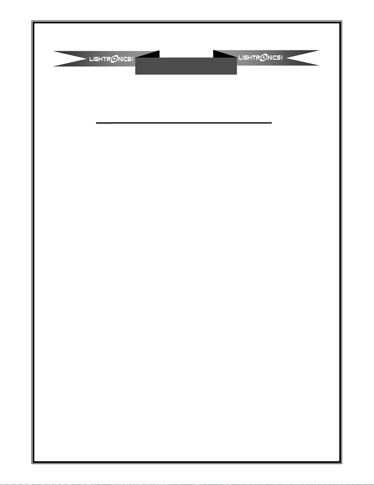
USING THE MENUS
The TL-5024 uses a menu system to control four functions. They are the CUEING, CHASER, PATCH, and
ERASE functions. Some menus have more than one display screen. The menus are accessed by pushing the
ENTER button. The diagram below shows the overall layout of the menus. The arrow characters shown in some
of the displays tell which button to push to change a value or advance to another item.
LCD STATUS DISPLAY
B01 Q000
C01 N001
ENTER
EXIT
MENU
All EXIT selections return to the normal LCD STATUS DISPLAY
CUEING
CHASER
ENTER
ENTER
PATCH
ERASE
ENTER
ENTER
EXIT
ERASE
EXIT
PATCH
EXIT
CHASER
EXIT
CUEING
ERASE
CUEING
PAGE=1
REPATCH
ENTER
C01 S01
EDIT
ENTER
CUE BK01
C01 SC01
ERASE
CHASER
COPYPAGE
1 TO 2
DIM 001
C0N 01
ENTER
BNK:SCN
01:01
CUE FI02
C01 FO02
ERASE
SCENES
1:1PATCH
ZERO ALL
CHN:01
OFF
ERASE
SOFTPTCH
ERASE
ALL!
www.lightronics.com
Lightronics Inc. 509 Central Drive Virginia Beach, VA 23454 tel 757 486 3588
Page 12
Page 12 of 13
Version 0.93 OWNERS MANUAL 07/20/2012
TL-5024 LIGHTING MEMORY CONSOLE
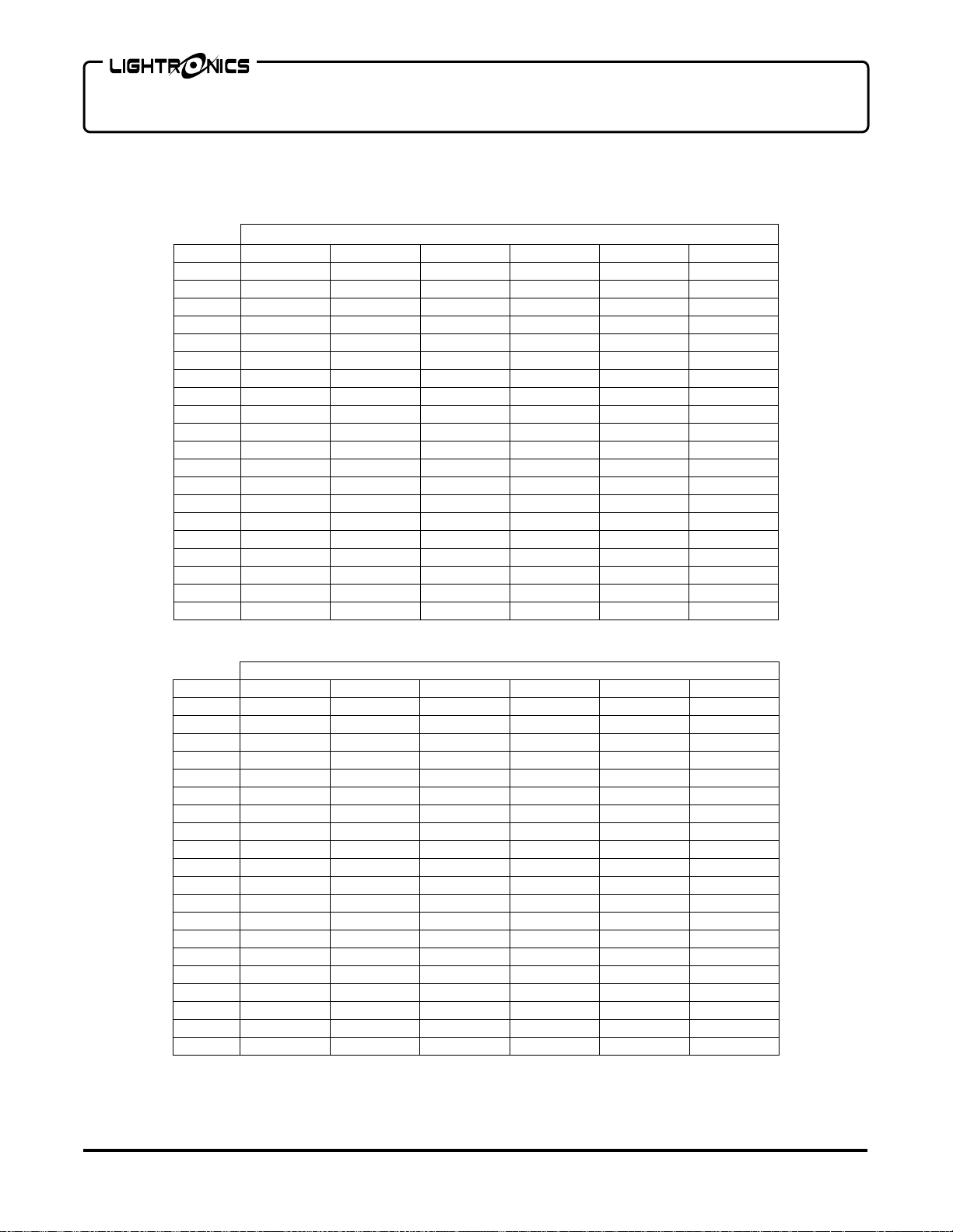
DEFAULT CHASE SCENE ASSIGNMENTS
The following assignments will be made when ERASE CHASER or ERASE ALL is run.
STEP #
1 B01 SC01 B02 SC01 B03 SC01 B04 SC01 B05 SC01 B06 SC01
2 B01 SC02 B02 SC02 B03 SC02 B04 SC02 B05 SC02 B06 SC02
3 B01 SC03 B02 SC03 B03 SC03 B04 SC03 B05 SC03 B06 SC03
4 B01 SC04 B02 SC04 B03 SC04 B04 SC04 B05 SC04 B06 SC04
5 B01 SC05 B02 SC05 B03 SC05 B04 SC05 B05 SC05 B06 SC05
6 B01 SC06 B02 SC06 B03 SC06 B04 SC06 B05 SC06 B06 SC06
7 B01 SC07 B02 SC07 B03 SC07 B04 SC07 B05 SC07 B06 SC07
8 B01 SC08 B02 SC08 B03 SC08 B04 SC08 B05 SC08 B06 SC08
9 B01 SC09 B02 SC09 B03 SC09 B04 SC09 B05 SC09 B06 SC09
10 B01 SC10 B02 SC10 B03 SC10 B04 SC10 B05 SC10 B06 SC10
11 B01 SC11 B02 SC11 B03 SC11 B04 SC11 B05 SC11 B06 SC11
12 B01 SC12 B02 SC12 B03 SC12 B04 SC12 B05 SC12 B06 SC12
13 END END END END END END
14 END
15 END
16 END
17 END
18 END
19 END
20 END
1 2 3 4 5 6
END
END
END
END
END
END
END
CHASE NUMBER
END
END
END
END
END
END
END
END
END
END
END
END
END
END
END
END
END
END
END
END
END
END
END
END
END
END
END
END
STEP #
1 B07 SC01 B08 SC01 B09 SC01 B10 SC01 B11 SC01 B12 SC01
2 B07 SC02 B08 SC02 B09 S0C2 B10 SC02 B11 SC02 B12 SC02
3 B07 SC03 B08 SC03 B09 SC03 B10 SC03 B11 SC03 B12 SC03
4 B07 SC04 B08 SC04 B09 SC04 B10 SC04 B11 SC04 B12 SC04
5 B07 SC05 B08 SC05 B09 SC05 B10 SC05 B11 SC05 B12 SC05
6 B07 SC06 B08 SC06 B09 SC06 B10 SC06 B11 SC06 B12 SC06
7 B07 SC07 B08 SC07 B09 SC07 B10 SC07 B11 SC07 B12 SC07
8 B07 SC08 B08 SC08 B09 SC08 B10 SC08 B11 SC08 B12 SC08
9 B07 SC09 B08 SC09 B09 SC09 B10 SC09 B11 SC09 B12 SC09
10 B07 SC10 B08 SC10 B09 SC10 B10 SC10 B11 SC10 B12 SC10
11 B07 SC11 B08 SC11 B09 SC11 B10 SC11 B11 SC11 B12 SC11
12 B07 SC12 B08 SC12 B09 SC12 B10 SC12 B11 SC12 B12 SC12
13 END END END END END END
14 END
15 END
16 END
17 END
18 END
19 END
20 END
7 8 9 10 11 12
END
END
END
END
END
END
END
CHASE NUMBER
END
END
END
END
END
END
END
END END END
END END END
END END END
END END END
END END END
END END END
END END END
www.lightronics.com
Lightronics Inc. 509 Central Drive Virginia Beach, VA 23454 tel 757 486 3588
Page 13
Y
All Lightronics products are warranted for a period of TWO/FIVE YEARS from the date of
purchase against defects in materials and workmanship.
WARRANT
A) If service is required, you may be asked to provide proof of purchase from an authorized
Lightronics dealer.
B) The FIVE YEAR WARRANTY is only valid if the warranty card is returned to Lightronics
accompanied with a copy of the original receipt of purchase within 30 DAYS of the
purchase date, if not then the TWO YEAR WARRANTY applies. Warranty is valid only for
the original purchaser of the unit.
C) This warranty does not apply to damage resulting from abuse, misuse, accidents, shipping,
and repairs or modifications by anyone other than an authorized Lightronics service
representative.
D) This warranty is void if the serial number is removed, altered or defaced.
E) This warranty does not cover loss or damage, direct or indirect arising from the use or
inability to use this product.
F) Lightronics reserves the right to make any changes, modifications, or updates as deemed
appropriate by Lightronics to products returned for service. Such changes may be made
without prior notification to the user and without incurring any responsibility or liability for
modifications or changes to equipment previously supplied. Lightronics is not responsible
for supplying new equipment in accordance with any earlier specifications.
G) This warranty is the only warranty either expressed, implied, or statutory, upon which the
equipment is purchased. No representatives, dealers or any of their agents are authorized
to make any warranties, guarantees, or representations other than expressly stated herein.
H) This warranty does not cover the cost of shipping products to or from Lightronics for
service.
I) Lightronics Inc. reserves the right to make changes as deemed necessary to this warranty
without prior notification.
Lightronics Inc. 509 Central Drive Virginia Beach, VA 23454 20050125
Page 14

www.lightronics.com
Lightronics Inc. 509 Central Drive Virginia Beach, VA 23454 tel 757 486 3588
 Loading...